Prospects of employing superconducting stripline resonators for studying the dynamical Casimir effect experimentally
Abstract
We discuss the prospects of employing an NbN superconducting microwave stripline resonator for studying the dynamical Casimir effect experimentally. Preliminary experimental results, in which optical illumination is employed for modulating the resonance frequencies of the resonator, show that such a system is highly promising for this purpose. Moreover, we discuss the undesirable effect of heating which results from the optical illumination, and show that degradation in noise properties can be minimized by employing an appropriate design.
pacs:
42.50.Dv, 42.50.Lc, 42.60.Da, 42.60.FcThe term dynamical Casimir effect (DCE) refers usually to the problem of an electromagnetic (EM) cavity with periodically moving walls. The quantum theory of electrodynamics predicts that under appropriate conditions, photons should be created in such a cavity out of the vacuum fluctuations Moore (1970). Such motion-induced radiation is closely related to the Unruh - Davies effect, which predicts that an observer of the EM field in a uniformly accelerating frame would measure thermal radiation with an effective temperature given by , where is the acceleration, is the Boltzmann’s constant, and is the light velocity in vacuum. Moreover, the equivalence principle of general relativity relates the later effect with the so-called Hawking radiation of black holes Fulling and Davies (1976); DeWitt (1975); Hawking (1974); Rosu (2001); Yurke and Potasek (1987).
Efficient production of photons can be achieved by employing parametric resonance conditions Dodonov and Klimov (1996). Consider the case where the cavity walls oscillate at twice the resonance frequency of one of the cavity modes (primary parametric resonance). In this case the angular resonance frequency varies in time according to
| (1) |
The system’s response to such an excitation depends on the dimensionless parameter , where is the quality factor of the resonator Landau and Lifshitz (1960). When , the system is said to be in the sub-threshold region, while above threshold, when , the system breaks into oscillations. Achieving the condition requires that the shift in the resonance frequency exceeds the width of its peak.
So far the DCE has not been verified experimentally Braggio et al. (2005); Kim et al. (2006). It turns out that creation of photons in the case of a cavity with moving walls requires that the peak velocity of the moving walls must be made comparable to light velocity, a task which is extremely difficult experimentally Dodonov (2001). When this is not the case the system is said to be in the adiabatic regime, where the thermal average number of photons is time independent.
An alternative method for realizing the DCE was pointed out by Yablonovitch Yablonovitch (1989), who proposed that modulating the dielectric properties of a material in an EM cavity might be equivalent to moving its walls. As a particular example, he considered the case of modulating the dielectric constant of a semiconductor by optical pulses that create electron-hole pairs. The modulation frequency achieved by this method is limited by the recombination time of electron-hole pairs, which can be relatively fast in some semiconductors Lozovik et al. (1995). Based on these ideas, a novel experimental approach for the detection of the DCE was recently proposed Braggio et al. (2005). However, implementing this approach might be very difficult Dodonov and Dodonov (2005). The change in the dielectric constant that occurs due to creation of electron-hole pairs in a semiconductor can be found by employing the Drude model Ashcroft and Mermin (c1976). In the microwave region one finds (see Eq. (1.35) of Ref. Ashcroft and Mermin (c1976)), where is the momentum relaxation time, and is the angular frequency. However, for all known semiconductors in the microwave region , and consequently, unless the resonator is carefully designed, exciting charge carriers will mainly lead to undesirable broadening of the resonance peaks while the frequency shift is expected to be relatively small.
On the other hand, parametric excitation by modulating can be implemented with a superconductor instead of a semiconductor. Optical radiation in the latter case allows modulation of the relative density of superconducting electrons and that of normal electrons. The resultant change in the dielectric constant , which can be found from the two-fluid model Orlando and Delin (1991), depends on the ratio between the London length and the skin depth of normal electrons . According to London’s theory the ratio between these length scales is given by , where is the London length at zero temperature (see Eqs. (14.21) and (34.9) of Ref. Ashcroft and Mermin (c1976)). Consequently, in the microwave region one finds Xu et al. (1996). This property of superconductors significantly facilitates achieving parametric gain by optically modulating since frequency shift can be made much larger in comparison with an undesirable peak broadening (see Eq. (A4) in Ref. Golosovsky et al. (1995)). Indeed, quasi-static resonance frequency shift by optical radiation Cho and Son (2003); Tsindlekht et al. (1994), or high-energy particles Day et al. (2003) (for which the required condition has been achieved) has been demonstrated.
In the present paper we discuss the prospects of employing a superconducting stripline resonator for experimentally studying the DCE. Our preliminary results show that such a system is highly promising for this purpose. In particular we show that achieving parametric gain by optically modulating the resonance frequency is feasible. We employ a novel configuration in which a hot electron detector (HED) is implemented as an integrated part of a microwave superconducting NbN stripline resonator. An optical pulse impinging on the HED results in a generation of hotspots, namely, small sections of the HED are heated above the superconducting critical temperature and thus undergo a transition from the superconducting phase to the normal one Kadin and Johnson (1996). As a result the impedance of the HED is substantially modified Saeedkia et al. (2005). Both the change in the resistive and inductive parts of the HED impedance contributes to the resonance shift Day et al. (2003); Arbel-Segev et al. (2006a), whereas the undesirable change in the damping rate is relatively small. In general however, employing such a modulation scheme results in some undesirable heating of the illuminated superconductor; whereas the quantum nature of the DCE requires operating at vary low temperatures. In the last part of this paper we discuss theoretically the expected effect of such heating on the noise properties of the system. In particular, we study the conditions for achieving noise squeezing when homodyne detection scheme is employed for readout. Our results show that the undesirable effect of heating can be minimized by employing an appropriate design. Note that, noise squeezing, which is expected to occur in the sub-threshold region, bares the same underlying physics as the DCE in the overcritical region Dodonov et al. (1990); Dodonov and Andreata (1999); Lozovik et al. (1995); Plunien et al. (2000).
The design of the resonator takes advantage of recent progress in the field of superconducting single photon detectors. Switching time in superconductors is usually limited by the relaxation process of high-energy quasi-particles, also called ’hot-electrons’, giving their energy to the lattice, and recombining to form Cooper pairs. Recent experiments with such photodetectors have demonstrated an intrinsic switching time on the order of and a counting rate exceeding (see Goltsman et al. (2005) and references therein). The circuit layout is illustrated in inset of Fig. 1. The resonator is designed as a stripline ring, having a characteristic impedance of . It is composed of -nm-think NbN film deposited on a Sapphire wafer. The first few resonance frequencies fall within the range of . A feedline, weakly coupled to the resonator, is employed for delivering the input and output signals. A HED is integrated into the structure of the ring. Its angular location, relative to the feedline coupling location, maximizes the RF current amplitude flowing through it in one of the resonance modes, and thus maximizes its coupling to that mode. The HED has a meander shape (inset of Fig. 1) that consists of nine strips. Each strip has a characteristic area of and the strips are separated one from another by approximately Zhang et al. (2003). The HED operating point can be maintained by applying dc bias. The dc bias lines are designed as two superconducting on-chip low-pass filters (LPF). A cut of is made in the perimeter of the resonator, to force the dc bias current flow through the HED. Further design considerations, fabrication details as well as calculation of normal modes can be found elsewhere Arbel-Segev et al. (2006a). Measurements are carried out in a fully immersed sample in liquid Helium.
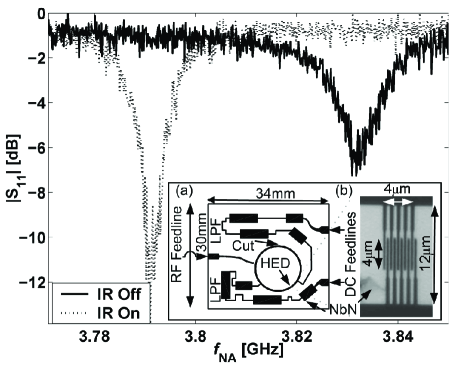
The effect of infrared (IR) laser illumination on one of the resonance frequencies of the resonator is shown in Fig. 1, which exhibits two reflection coefficient () measurements which were performed near the second resonance frequency and obtained using a network analyzer. The HED is biased with a sub-critical dc current of , which only slightly increases the damping rate relative to the measured damping rate in the case where the HED is unbiased (the critical dc current while injecting the RF signal is ). The solid curve was taken without illumination whereas the dotted curve was taken while the device was being illuminated by a monochromatic IR laser light having a wavelength of and an effective power of . One notes that under illumination the resonance frequency substantially red shifts while the damping rate surprisingly decreases. This is caused by the fact that as the impedance of the HED is modified the RF current is repelled out of the HED and redistributes in the ring Arbel-Segev et al. (2006a), and consequently the damping rate decreases. This measurement demonstrates frequency tuning by monochromatic IR illumination, which is characterized by the parameter .
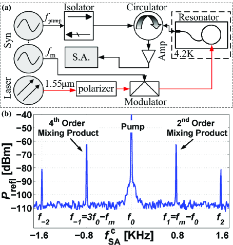
Fast modulation of the resonance frequency is performed using the experimental setup depicted in Fig. 2. The resonator is excited by a monochromatic pump tone, having a power of dBm, at . The optical power impinging on the HED, which has an average value of fW, is modulated at frequency , using a Mach-Zender modulator, driven by a second monochromatic signal, phase locked with the first one. The frequency offset is chosen to be much smaller than the resonance width . Note that the laser power is approximately eight orders of magnitude lower than the power used in the experimental approach proposed by Braggio et al. Braggio et al. (2005). Fig. 2 shows the reflected power off the resonator as a function of the measured spectrum analyzer (SA) frequency , centralized on . It shows five distinguished tones. The strongest one, labeled as , is the reflected spectral component at the frequency of the stimulating pump tone . The other four tones are found at frequencies . For example, and tones results from second and fourth order mixing between the power-modulated optical signal and the driving pump tone respectively. No dc bias current is employed in this measurement; however, the pump power is tuned such that the HED is driven into a sub-critical region, close to a threshold of a nonlinear instability Abdo et al. (2006a, b); Arbel-Segev et al. (2006b, c, d).
The results presented above demonstrate modulation of the resonance frequency at the frequency of the primary parametric resonance. Furthermore, the parametric gain threshold condition is achieved using optical illumination having a fixed power. The main problem, which currently prevents the achievement of parametric gain, is the relatively low photon flux that impinges the HED. Due to losses along the optical path, especially the expansion of the Gaussian beam from the tip of the fiber to the HED, the largest photon flux, we currently manage to apply, is approximately photons per modulation cycle, at twice the resonance frequency. When taking into account the quantum efficiency of the HED, which is probably lower than Korneev et al. (2004), and its effective area, which is probably smaller than its printed area, we estimate that the optical power flux is about two orders of magnitude lower than the threshold power. Focusing the laser beam in future devices will allow overcoming this limitation.
Note however that, as was discussed above, the optical illumination employed for parametric excitation results in some undesirable heating and consequently an elevated noise. To study the noise properties of the system theoretically, we employ a model in which the contribution of damping is taken into account by adding a fictitious port coupled linearly to the resonator. The modes, in both the feedline and in the damping port, are assumed to be in thermal equilibrium at temperatures and respectively. Assume the case where no RF signals are injected from noisy instruments at room temperature, and the feedline is employed only for delivering the outgoing signal from the resonator. In this case, employing an ultra-low noise cryogenic amplifier, directly coupled to the feedline, may allow to be very close to the base temperature of the refrigerator. On the other hand, might be much higher due to the optical illumination. Assuming that damping in the resonator occurs mainly in the illuminated section, one may assume that is close to the temperature of that section. In general, however, modulating the optical power drives that section out of thermal equilibrium, thus should be considered as an effective temperature characterizing the non-equilibrium distribution. For the conditions appropriate for achieving parametric gain one may assume that is close to the critical temperature of the superconductor .
When the resonance frequency varies in time according to Eq. (1) the system acts as a phase sensitive amplifier Movshovich et al. (1990). The phase dependence can be studied by employing homodyne detection, namely, by mixing the output signal, reflected off the resonator, with a local oscillator at angular frequency (the parametric excitation is at frequency ) and with an adjustable phase . We calculate the power spectrum of the homodyne detector output, in the sub-threshold region, at angular frequency . We find that is periodic in with period . We denote the minimum value as (squeezed quadrature) and the maximum one as (amplified quadrature). The derivation is similar to the one presented earlier in Ref. Yurke and Buks (2005), thus we only state here the final results
| (2) |
where , is the unloaded quality factor of the resonator, which is related to the loaded quality factor by , where characterizes the coupling between the resonator and the feedline.
Vacuum noise squeezing occurs when . Consider as an example the case where , , , , , , and . Using Eq. (2) one finds . This example demonstrates that vacuum noise squeezing can be achieved even when , provided that the coupling to the feedline is made sufficiently strong.
In summary, we present preliminary experimental results which suggest that NbN superconducting stripline resonators may serve as an ideal tool for studying the DCE experimentally. Moreover we study theoretically the noise properties of the system and find that vacuum noise squeezing may be achieved even when the optical illumination employed for parametric excitation causes a significant local heating.
This work was supported by the Israeli defense ministry, Israel Science Foundation under grant 1380021, the Deborah Foundation and Poznanski Foundation. One of the authors E.B. would especially like to thank Michael L. Roukes for supporting the early stage of this research and for many helpful conversations and invaluable suggestions.
References
- Moore (1970) G. T. Moore, J. Math. Phys. 11, 2679 (1970).
- Fulling and Davies (1976) S. A. Fulling and P. C. W. Davies, Proc. R. Soc. Lond. 348, 393 (1976).
- DeWitt (1975) B. S. DeWitt, Phys. Rep. 19C, 295 (1975).
- Hawking (1974) S. W. Hawking, Nature 248, 30 (1974).
- Rosu (2001) H. C. Rosu, Grav. and Cosmology 7, 1 (2001), arXiv:gr-qc/9406012.
- Yurke and Potasek (1987) B. Yurke and M. Potasek, Phys Rev. A 36, 3464 (1987).
- Dodonov and Klimov (1996) V. V. Dodonov and A. B. Klimov, Phys. Rev. A 53, 2664 (1996).
- Landau and Lifshitz (1960) L. D. Landau and E. M. Lifshitz, Mechanics (Pergamon, 1960).
- Braggio et al. (2005) C. Braggio, G. Bressi, G. Carugno, C. D. Noce, G. Galeazzi, A. Lombardi, A. Palmieri, G. Ruoso, and D. Zanello, Europhys. Lett. 70, 754 (2005).
- Kim et al. (2006) W.-J. Kim, J. H. Brownell, and R. Onofrio, Phys. Rev. Lett. 96, 200402 (2006).
- Dodonov (2001) V. V. Dodonov, Modern Nonlinear Optics, vol. 119 of Advances in Chemical Physics (Wiley, New York, 2001), p. 309.
- Yablonovitch (1989) E. Yablonovitch, Phys. Rev. Lett. 62, 1742 (1989).
- Lozovik et al. (1995) Y. E. Lozovik, V. G. Tsvetus, and E. A. Vinogradov, Physica Scripta 52, 184 (1995).
- Dodonov and Dodonov (2005) V. V. Dodonov and A. V. Dodonov, j. russ. las. res. 26, 445 (2005).
- Ashcroft and Mermin (c1976) N. W. Ashcroft and N. D. Mermin, Solid State Physics (Saunders College, Philadelphia, c1976).
- Orlando and Delin (1991) T. Orlando and K. A. Delin, Foundations of Applied Superconductivity (Prentice Hall, 1991).
- Xu et al. (1996) K.-X. Xu, S. Zhou, and J.-S. Bao, j. supercond. 9, 193 (1996).
- Golosovsky et al. (1995) M. A. Golosovsky, H. J. Snortland, and M. R. Beasley, Phys. Rev. B 51, 6462 (1995).
- Cho and Son (2003) S. Cho and C.-S. Son, IEEE Trans. Appl. Superconduct. 13, 3659 (2003).
- Tsindlekht et al. (1994) M. Tsindlekht, M. Golosovsky, H. Chayet, and D. Davidov, Appl. Phys. Lett. 65, 2875 (1994).
- Day et al. (2003) P. K. Day, H. G. LeDuc, B. A. Mazin, A. Vayonakis, and J. Zmuidzinas, Nature 425, 817 (2003).
- Kadin and Johnson (1996) A. M. Kadin and M. W. Johnson, Appl. Phys. Lett. 69, 3938 (1996).
- Saeedkia et al. (2005) D. Saeedkia, A. H. Majedi, S. Safavi-Naeini, and R. R. Mansour, IEEE Microwave Wireless Compon. Lett. 15, 510 (2005).
- Arbel-Segev et al. (2006a) E. Arbel-Segev, B. Abdo, O. Shtempluck, and E. Buks, IEEE Trans. Appl. Superconduct. (to be published) 16 (2006a), arXiv: cond-mat/0601190.
- Dodonov et al. (1990) V. V. Dodonov, A. B. Klimov, and V. I. Man’ko, Phys. Lett. A 149, 225 (1990).
- Dodonov and Andreata (1999) V. V. Dodonov and M. A. Andreata, J. Phys. A 32, 6711 (1999).
- Plunien et al. (2000) G. Plunien, R. Schutzhold, , and G. Soff, Phys. Rev. Lett. 84, 1882 (2000).
- Goltsman et al. (2005) G. N. Goltsman, A. Korneev, I. Rubtsova, I. Milostnaya, G. Chulkova, O. Minaeva, K. Smirnov, B. Voronov, W. Sysz, A. Pearlman, et al., Phys. Status Solidi C 2, 1480 (2005).
- Zhang et al. (2003) J. Zhang, W. Slysz, A. Verevkin, O. Okunev, G. Chulkova, A. Korneev, A. Lipatov, G. N. Goltsman, and R. Sobolewski, IEEE Trans. Appl. Superconduct. 13, 180 (2003).
- Abdo et al. (2006a) B. Abdo, E. Segev, O. Shtempluck, and E. Buks, Phys. Rev. B 73, 134513 (2006a).
- Abdo et al. (2006b) B. Abdo, E. Segev, O. Shtempluck, and E. Buks, Appl. Phys. Lett. 88, 022508 (2006b).
- Arbel-Segev et al. (2006b) E. Arbel-Segev, B. Abdo, O. Shtempluck, and E. Buks (2006b), arXiv: cond-mat/0607259.
- Arbel-Segev et al. (2006c) E. Arbel-Segev, B. Abdo, O. Shtempluck, and E. Buks (2006c), arXiv: cond-mat/0607261.
- Arbel-Segev et al. (2006d) E. Arbel-Segev, B. Abdo, O. Shtempluck, and E. Buks (2006d), arXiv: cond-mat/0607262.
- Korneev et al. (2004) A. Korneev, P. Kouminov, V. Matvienko, G. Chulkova, K. Smirnov, B. Voronov, G. N. Goltsman, M. Currie, W. Lo, K. Wilsher, et al., Appl. Phys. Lett. 84, 5338 (2004).
- Movshovich et al. (1990) R. Movshovich, B. Yurke, P. G. Kaminsky, A. D. Smith, A. H. Silver, R. W. Simon, and M. V. Schneider, Phys. Rev. Lett. 65, 1419 (1990).
- Yurke and Buks (2005) B. Yurke and E. Buks (2005), arXiv:quant-ph/0505018.