Autonomous, Monocular, Vision-Based Snake Robot Navigation and Traversal of Cluttered Environments using Rectilinear Gait Motion
Abstract
Rectilinear forms of snake-like robotic locomotion are anticipated to be an advantage in obstacle-strewn scenarios characterizing urban disaster zones, subterranean collapses, and other natural environments. The elongated, laterally-narrow footprint associated with these motion strategies is well-suited to traversal of confined spaces and narrow pathways. Navigation and path planning in the absence of global sensing, however, remains a pivotal challenge to be addressed prior to practical deployment of these robotic mechanisms. Several challenges related to visual processing and localization need to be resolved to to enable navigation. As a first pass in this direction, we equip a wireless, monocular color camera to the head of a robotic snake. Visiual odometry and mapping from ORB-SLAM permits self-localization in planar, obstacle-strewn environments. Ground plane traversability segmentation in conjunction with perception-space collision detection permits path planning for navigation. A previously presented dynamical reduction of rectilinear snake locomotion to a non-holonomic kinematic vehicle informs both SLAM and planning. The simplified motion model is then applied to track planned trajectories through an obstacle configuration. This navigational framework enables a snake-like robotic platform to autonomously navigate and traverse unknown scenarios with only monocular vision.
I Introduction
Navigation through cluttered environments, often describing natural disaster aftermaths, subterranean collapses and similar senarios, is a challenge that snake-like robotic platforms are well-positioned to address. Mimicry of snake-like morphologies and adoption of serpentine locomotion strategies potentially confer locomotive advantages similar to those employed by biological counterparts traversing similar environments. Given the current challenges associated to traversal of arbitrary, unknown, rugged terrains, we focus the problem scope to navigation through a unknown planar environments with obstacles.
A frequent characterization of these mission scenarios entails the absence of global environmental knowledge. Success requires adequate onboard sensing and navigation strategies in the presence of obstacles, which includes self-localization, map construction and motion planning [1]. Snake-like robotics research has focused on the latter, path planning and following, with less effort on addressing the former challenges. Morphological features that advantage snake-like platforms in obstacle-strewn environments also limit them with respect to the supported onboard sensory equipment. Head-mounted cameras obtain visual information which, in conjunction with proprioception-based dead reckoning, informs localization [2]. Cameras on these robotic platforms have predominantly been used to address higher task-level objectives or monitoring needs rather than navigational autonomy [1, 3]. Other perceptual modalities such as ultrasonic range sensors may be used to initiate reactive obstacle avoidance [4, 3, 5]. Laser range finders have also been applied to support SLAM for snake robots [6, 4, 5].
Given a representation of the environment, path planning may be accomplished. Approaches exploit simplified kinematic modes of travel for hyper-redundant mechanisms. For active wheeled or tracked platforms, follow-the-leader-like motion planning suffices [7, 8, 9]. Other planners focus on wheel-less snake-like robots and exploit locomotive reduction of gaits to differential-drive vehicle models for which control is well-understood; in demonstration, however, they have presumed global knowledge of the environment [10, 11, 12]. Integration of SLAM and path planning to accomplish navigation is challenging for snake-like platforms due to weight as well as footprint restrictions. Alternative vehicles operating terrestrially [13, 14, 15], aerially [16, 17], as well as aquatically [18, 19, 20], have addressed similar navigational challenges, utilizing different sensing strategies. However, mapping and self-localization, a key component for autonomous navigation, remains largely unexplored on bio-inspired robotic platforms.
Contribution. We equip a snake-like robotic mechanism with a low-resolution, monocular camera. This sensing modality, in conjunction with a reduced kinematic model of rectilinear motion, informs ORB-SLAM to accomplish self-localization in complex, obstacle-cluttered environments. Ground plane segmentation and ego-centric, perception space collision checking facilitate trajectory planning under the assumption of a reduced kinematic unicycle motion model. Lifting the reduced dynamics, and corrective feedback modifications, to the actual locomotion gait leads to execution of the planned trajectories. Relying on monocoluar vision, the presented framework enables a snake-like robotic platform to both navigate and traverse unknown environments.
II Rectilinear Gait Model
We briefly review a prior presentation of the traveling wave rectilinear gait and associated dynamics in [21, 12]. The snake-like robot is represented as a mechanical system whose state decomposes into a shape component, , and a group component, , with body velocity, . The reduced Lagrange-d’Alembert dynamical formulation is [22]:
| (1) |
where is the shape space control signal, is the vertical body velocity, is the vertical body momentum, and is the local principle connection defining the horizontal and vertical split. The net external wrench acting on the body frame, , models the influence of the external environment.
II-A Time-varying Gait Shape
The time-varying gait shape for rectinilinear motion is formulated with respect to an average body curve, parametrized by arclength, , as well as an accompanying average body frame rigidly attached to the average body at midpoint, . Vertical lift of the gait shape from the ground is modeled in the plane, however, locomotion dynamics are modeled in the ground, , plane.
A sinusoidal wave traveling rostrally along the body in the body plane models the rectilinear gait, with time varying shape equations,
| (2) |
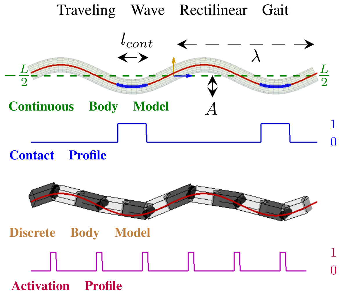
where is the body curve parameter (see Figure 1) and captures planar curvature of the average body (dashed green) in the - modeling plane, assumed constant along the length of the body. The variables , and parametrize the traveling wave amplitude, wavelength and frequency, respectively while denotes time.
Figure 1 (top) illustrates the continuous body model, in the - plane. A contact profile (beneath), parametrized by , defines time varying locations on the body in contact with ground. The - and - (into the page) coordinate vectors comprise the rigid body frame with respect to which body frame dynamics are modeled, in the locomotion plane.
The rigid multi-link structure of the robotic snake (lower snake image in Figure 1), in contrast to a continous body model, may only effect curvature about joint locations along the body and not when the flat face of the discrete link is flush to the ground. To accomodate this distinction an activation profile is introduced, illustrated in Figure 1 (bottom). Pulses of the profile coincide with joint locations along the body which can curve or roll and produce propulsion through a rolling friction model with the environment. All other regions of the body coincide with link interiors, incapable of effecting curvature; they instead produce drag.
II-B Dynamical Model Reduction
The traveling wave rectilinear gait has sufficient structure that the equations of motion simplify. We advance to the modeling results most relevant to this work and refer the reader to [21, 12] for specifics.
A rolling viscous friction model is employed to model environmental caudal-rostral forcing produced at points of body-ground contact. Given the friction coefficients , , and , individual link masses, and the contact and activation profiles, numerical integration of the system dynamics permits recovery of the body velocity of the robot as a function of time for a particular set of gait parameters.
Figure 2 illustrates the resulting relationship, generated from repeated numerical integration simulations sweeping a wide range of traveling wave amplitude, , and average body curvature values, . Averaged steady-behavior body velocity of the system is captured as a function over gait parameter space, . Linear body velocity components remained largely invariant with respect to traveling wave amplitude, , and average body curvature, . Averaged steady-behavior body velocity laterally, , is negligible while that in the forward direction, , remains positive and nearly constant. Variation of traveling wave amplitude has little impact on the averaged steady-behavior motion of the system. Angular velocity varies linearly with average body curvature, .
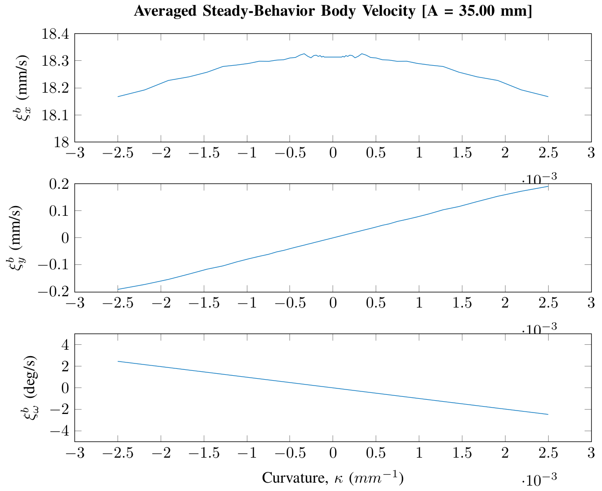
The linear relation between and turn rate, as well as the result that linear body velocity remains fairly constant, reveals a strong resemblance of this system to a fixed forward-velocity unicycle model, whereby , serves as the steering control parameter. We denote the inverse mapping of by where is a given angular velocity. It is maintained as a linear fit of data plotted in Figure 2. The mapping, effectively reduces the traveling wave rectilinear gait dynamics to that of a kinematic unicycle vehicle, reminiscent of [23]. Classical techniques for path tracking are applicable; body velocities required to rectify following errors are expeditiously mapped to corresponding body curvatures that produce the required motion.
III Perception and Planning
A monocular radio frequency (RF) camera attached to the head of a -link robotic snake with scales [24] supports localization and planning. The camera continually transmits a analog color image to a stationary PC. All computation related to navigation, tracking and control is processed on this PC with the final body shape commands transmitted, through a lightweight tether, to the robot for locomotion. The intent behind the wireless transmission method is to limit the thickness of the tether to improve maneuverability.
The traveling wave rectilinear gait entails sinusoidal, time-varying body shape changes over time. As a result, the camera frame is in constant motion during the course of gait of execution, both spatially and with respect to the robot body frame. Visual sensing of the environment operates at one frame per gait cycle (i.e., every seconds), coinciding with gait phase during which velocity of the camera frame is minimal to reduce motion blur. Applying the unicycle motion model [12] to the previous pose estimate provides a predicted pose for the robot as a function of the current commanded gait curvature (). Each kept image frame and predicted pose is sent to a custom ORB-SLAM implementation for estimating visual odometry during locomotion. From there, a vision-based path planner confirms the current trajectory or returns a new path to follow for collision avoidance.
III-A Simultaneous Localization and Mapping (SLAM)
ORB-SLAM [25] is chosen mostly due to the robustness of ORB feature descriptor [26]. Other popular real-time methods use direct visual odometry/SLAM (e.g. SVO [27], DSO [28]), which relies on consistent illumination and low noise in the video input. In our platform, the assumptions required by direct methods are easily violated due to the target application, the on-board sensor, and transmission-based image corruption. Feature-based ORB-SLAM is more robust to these nuisance factors: it provides reliable odometry and 3D map points when working with rolling shutter camera under image transmission induced noise. One limitation of visual odometry/SLAM with monocular camera is that, it cannot provide accurate scale estimation since scale is not observable given monocular video input. For visual odometry/SLAM to be useful in planning & control, two enhancements are added to monocular ORB-SLAM, enabling it to provide well-bounded scale estimation.
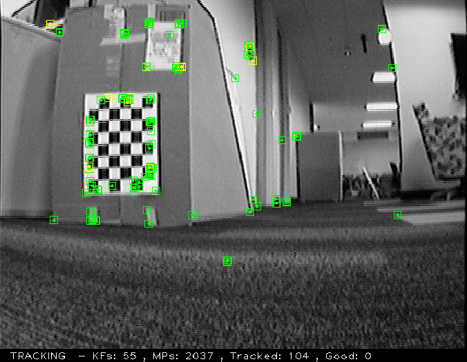
SLAM Initialization. Rather than employ the built-in, randomized initialization strategy of ORB-SLAM, programmed snake movements with known relative pose seeds the SLAM initialization. With known head movements between captured frames, see Fig. 8 left, the unknown scale is fixed; additionally, the initialization problem changes from a structure-and-motion estimation to structure-only estimation for initializing the map points. The images used for SLAM initialization are captured with the widest baseline that the robot can provide through body movement (without tipping over), thereby reducing the triangulation error of 3D mapped features, relative to a typical motion-based initialization.
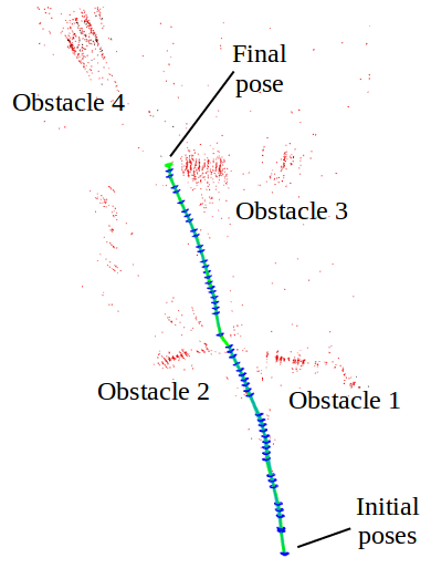
Motion Model for Feature Matching Prior. Though the scale is estimated accurately at the initialization, it degenerates easily as the small estimation error accumulates in the frame-by-frame tracking process of SLAM. We incorporate the snake unicycle motion model as the motion prior in frame-by-frame tracking so as to bound the scale drift during the tracking of ORB-SLAM. Only those features matchings that agree with the prior are accepted and utilized in frame-by-frame tracking. Doing so reduces the estimation error and the scale drift during tracking in ORB-SLAM. The enhanced pose tracking and 3D mapping are illustrated in Fig. 3 right.
III-B Perception Space Trajectory Planning
Monocular, color vision does not recover dense depth of generic scenes, while the monocular SLAM processing does not provide dense scene geometry. To overcome the lack of depth knowledge from monocular streams, we employ ground-plane traversability tests to segment the sensed environment into traversable and non-traversable components [29, 30, 31, 32, 33]. When coupled with a flat ground-plane assumption, traversable regions can be used to test the collision-free feasibility of potential forward moving snake paths. For planning and trajectory synthesis to naturally work with the segmented scene, it employs a perception space approach [34]. Instead of relying on a 3D world reconstruction from the monocular camera, the robot model is directly projected into image space for collision checking. The image itself is processed to obtain a binary image where false values indicate hypothesized non-ground regions of the world, e.g., obstacles, see Figure 4. The sample based planner selects from amongst the collision-free paths to identify the best path to follow. Planning in binary perception space gives a flexible modality to deploy our snake-like robotic platform for fast trajectory generation and collision checking.
Ground Plane Segmentation. Differentiating obstacles from ground uses a trained DCT-based support vector machine [35] to classify -by- pixel image blocks as ground versus not ground. The prevailing assumption is that the camera pose will always have ground regions extending from the central bottom of the image up towards the horizon, meeting with possible obstacle regions prior to hitting the horizon. Block-wise classification then yields a continuous ground-obstacle boundary expanding from the bottom-center of the image. A binary image is constructed whereby pixels below the boundary are designated traversable and those above are impassible (ie. obstacles). Figure 4 provides a visualization of the traversability segmentation of an input image.
Collision Checking. The planner uses a sample-based receding horizon strategy for synthesizing local paths and testing their fitness. In contrast to many path planning methods that assume a point based robot model, our method considers the entire snake-like robot model for performing collision checks. Given a trajectory to collision check, it is decomposed into several, closely-spaced navigation poses. For each navigation pose, the robot model with mm width front is hallucinated, using the calibrated intrinsic camera matrix, and a synthetic binary image is created for the robot head at that pose as viewed from the current camera configuration. Since there is a homographic assumption on the classified binary image data, only the footprint of the snake robot head (no height geometry) is hallucinated to create the future pose binary image. Due to the unicycle motion model, the snake body follows behind the head. Collision checks at the head are also valid for the body. The collision checking process involves evaluating the projected snake head region and the binary image for false labels. If the entire projected line fits in the ground plane area (only true labels), the current pose will not collide with obstacles.
Trajectory Sampling and Selection. The trajectory sampler generates multiple trajectories to be collision checked. From the current pose of the robot, a set of curved trajectories are generated based on near-identity diffeomorphism control trajectories for unicycle robots [34], where is an odd number so as to include the straight trajectory (plus an equal quantity going left as going right). We choose in our implementation. The chosen trajectory generation dynamics of the robot match the reduced order kinematic model of the snake robot. After checking all trajectory samples for collision, the longest trajectory is chosen as the one to follow.
IV Experiment
The presented navigation framework is experimentally deployed using a -link robotic snake operating over a carpeted surface. We task the robot to navigate through a non-trivial obstacle configuration, illustrated in Figure 5. Its initial objective is to travel a straight path along a corridor. However, the obstacles in its path will induce a sequence of trajectory re-plans as they are encountered. The robot begins on the left and attempts to proceed along a straight path from left to right.

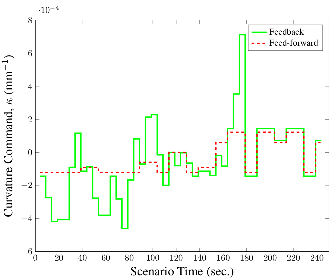
As obstacles come into view, ground segmentation outputs cause the path planning module to steer around them. A new path is re-planned every seconds (ie. every rectilinear gait cycles) based on the robot’s current position. Planned paths are represented as a sequence of waypoints. The furthest waypoint, within a ball of radius mm, is chosen as the target waypoint to which to travel. Robot pose errors with respect to this waypoint are used to compute an angular body velocity correction, (as foward velocity is constant), to the feedfoward angular velocity, , associated with the planned trajectory. The control-to-action mapping, , then maps the feedback corrected velocity to actionable curvature command, . Figure 6 illustrates the feedback-corrected curvature commands versus the original feedforward cuvature commands computed during the course of navigating the scenario of Figure 5. The feedback control strategy employed is similar to that used in [12, 36].
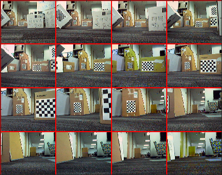
A time-lapsed series of images, captured from the head camera, are compiled in Figure 7. Despite a limited field of view of the surrounding environment and control constraints on the turning rate of the robot snake, the candidate trajectories generated circumvent obstacles. When multiple feasible trajectories are possible, the longest trajectory with least curvature is selected amongst the candidates. Feedback control then tracks the planned trajectory utilizing robot pose updates that are updated using ORB-SLAM until trajectory re-planning occurs. At that point, the newly selected trajectory segment is followed. The scenario completes when the robotic snake exits the obstacle field into the corridor on the right side of Figure 5. From the visual sequence it is clear that the robot snake maneuvers to navigate between the obstacles. The camera pose of the robot tracked by ORB-SLAM is illustrated in Fig 8, where the left image provides an example viewpoint and its set of tracked feature points, while the right side depicts the estimated trajectory.
V Conclusion
This work leverages a previously presented feedback control model for the traveling wave rectilinear gait of a snake-like robot. Reduction of the complex gait dynamics to a simpler kinematic unicycle model, in the steady-behavior motion, admits the application of tools and strategies targeted for differential drive vehicles; in particular, to trajectory planning and to trajectory tracking using feedback control. We augment the snake-like robotic platform with a wireless monocular head camera to capture images of the environment once every gait cycle. Future pose predictions derived from the gait motion model, in conjunction with captured visual information, inform ORB-SLAM which is tasked with self-localization in the environment. Ground segmentation of captured visual information then aids a perception space trajectory planner. Localization is critical to successful tracking of planned trajectories. The integrated snake localization and navigation system is experimentally deployed. The deployment self-localizes and dynamically plans through an unknown environment as visual information of the environment becomes available. Initially feasible trajectories are re-synthesized to navigate around detected obstacles. Using the presented navigation framework the robot successfully negotiated a scenario, avoiding obstacles as they came into view, and eventually exited the obstacle field. Future work aims to resolve the limitations of monocular cameras, both for localization and navigation, by using a stereo camera and appropriately upgrading the algorithmic system components.
References
- [1] F. Sanfilippo, J. Azpiazu, G. Marafioti, A. A. Transeth, Ø. Stavdahl, and P. Liljebäck, “A review on perception-driven obstacle-aided locomotion for snake robots,” in International Conference on Control, Automation, Robotics and Vision, Nov 2016, pp. 1–7.
- [2] X. Zhao, L. Dou, and Z. S. N. Liu, “Study of the navigation method for a snake robot based on the kinematics model with mems imu,” Sensors, vol. 18, 2018.
- [3] K. L. Paap, T. Christaller, and F. Kirchner, “A robot snake to inspect broken buildings,” in IEEE/RSJ International Conference on Intelligent Robots and Systems, vol. 3, Oct 2000, pp. 2079–2082.
- [4] M. Tanaka, K. Kon, and K. Tanaka, “Range-sensor-based semiautonomous whole-body collision avoidance of a snake robot,” IEEE Transactions on Control Systems Technology, vol. 23, no. 5, pp. 1927–1934, Sept 2015.
- [5] Q. Wu, J. Gao, C. Huang, Z. Zhao, C. Wang, X. Su, H. Liu, X. Li, Y. Liu, and Z. Xu, “Obstacle avoidance research of snake-like robot based on multi-sensor information fusion,” in IEEE International Conference on Robotics and Biomimetics, Dec 2012, pp. 1040–1044.
- [6] Y. Tian, V. Gomez, and S. Ma, “Influence of two SLAM algorithms using serpentine locomotion in a featureless environment,” in IEEE International Conference on Robotics and Biomimetics, Dec 2015, pp. 182–187.
- [7] L. Pfotzer, S. Klemm, A. Roennau, J. Zöllner, and R. Dillmann, “Autonomous navigation for reconfigurable snake-like robots in challenging, unknown environments,” Robotics and Autonomous Systems, vol. 89, pp. 123–135, 2017.
- [8] X. Fu and Y. Wang, “Research of snake-like robot control system based on visual tracking,” in International Conference on Electronics, Communications and Control, Sept 2011, pp. 399–402.
- [9] E. Caglav, A. M. Erkmen, and I. Erkmen, “A snake-like robot for variable friction unstructured terrains, pushing aside debris in clearing passages,” in IEEE/RSJ International Conference on Intelligent Robots and Systems, Oct 2007, pp. 3685–3690.
- [10] X. Xiao, E. Cappo, W. Zhen, J. Dai, K. Sun, C. Gong, M. Travers, and H. Choset, “Locomotive reduction for snake robots,” in IEEE International Conference on Robotics and Automation, 2015, pp. 3735–3740.
- [11] R. Hatton, R. Knepper, H. Choset, D. Rollinson, C. Gong, and E. Galceran, “Snakes on a plan: Toward combining planning and control,” in IEEE International Conference on Robotics and Automation, Karlsruhe, Germany, 2013, pp. 5174 – 5181.
- [12] A. Chang and P. Vela, “Closed-loop path following of traveling wave rectilinear motion through obstacle-strewn terrain,” in Proceedings of IEEE International Conference on Robotics and Automation, May 2017, pp. 3532–3537.
- [13] J. Zhang, G. Kantor, M. Bergerman, and S. Singh, “Monocular visual navigation of an autonomous vehicle in natural scene corridor-like environments,” in IEEE/RSJ International Conference on Intelligent Robots and Systems, Oct 2012, pp. 3659–3666.
- [14] H. Lategahn, A. Geiger, and B. Kitt, “Visual SLAM for autonomous ground vehicles,” in Proceedings of IEEE International Conference on Robotics and Automation, May 2011, pp. 1732–1737.
- [15] S. García, M. E. López, R. Barea, L. M. Bergasa, A. Gómez, and E. J. Molinos, “Indoor SLAM for micro aerial vehicles control using monocular camera and sensor fusion,” in International Conference on Autonomous Robot Systems and Competitions, May 2016, pp. 205–210.
- [16] A. Chambers, S. Scherer, L. Yoder, S. Jain, S. Nuske, and S. Singh, “Robust multi-sensor fusion for micro aerial vehicle navigation in gps-degraded/denied environments,” in American Control Conference, June 2014, pp. 1892–1899.
- [17] S. T. Nuske, S. Choudhury, S. Jain, A. D. Chambers, L. Yoder, S. Scherer, L. J. Chamberlain, H. Cover, and S. Singh, “Autonomous exploration and motion planning for an unmanned aerial vehicle navigating rivers,” Journal of Field Robotics, June 2015.
- [18] F. Hidalgo and T. Bräunl, “Review of underwater SLAM techniques,” in International Conference on Automation, Robotics and Applications, Feb 2015, pp. 306–311.
- [19] M. Hammond and S. M. Rock, “A SLAM-based approach for underwater mapping using AUVs with poor inertial information,” in IEEE/OES Autonomous Underwater Vehicles, Oct 2014, pp. 1–8.
- [20] A. Kim, “Active visual SLAM with exploration for autonomous underwater navigation,” Ph.D. dissertation, University of Michigan, 2012.
- [21] A. Chang, M. Serrano, and P. Vela, “Shape-centric modeling of traveling wave rectilinear locomotion for snake-like robots,” in IEEE Conference on Decision and Control, Las Vegas, NV, Dec 2016, pp. 7535 – 7541.
- [22] J. Ostrowski, “The Mechanics and Control of Undulatory Robotic Locomotion,” Ph.D. dissertation, California Institute of Technology, 1996.
- [23] X. Xiao, E. Cappo, W. Zhen, J. Dai, K. Sun, C. Gong, M. Travers, and H. Choset, “Locomotive reduction for snake robots,” in IEEE International Conference on Robotics and Automation, Seattle, WA, 2015.
- [24] M. Serrano, A. Chang, G. Zhang, and P. Vela, “Incorporating frictional anisotropy in the design of a robotic snake through the exploitation of scales,” in IEEE International Conference on Robotics and Automation, 2015, pp. 3729–3734.
- [25] R. Mur-Artal and J. D. Tardós, “ORB-SLAM2: an open-source SLAM system for monocular, stereo and RGB-D cameras,” IEEE Transactions on Robotics, vol. 33, no. 5, pp. 1255–1262, 2017.
- [26] E. Rublee, V. Rabaud, K. Konolige, and G. Bradski, “ORB: An efficient alternative to SIFT or SURF,” in IEEE International Conference on Computer Vision, 2011, pp. 2564–2571.
- [27] C. Forster, Z. Zhang, M. Gassner, M. Werlberger, and D. Scaramuzza, “SVO: Semidirect visual odometry for monocular and multicamera systems,” IEEE Transactions on Robotics, vol. 33, no. 2, pp. 249–265, 2017.
- [28] J. Engel, V. Koltun, and D. Cremers, “Direct sparse odometry,” IEEE Transactions on Pattern Analysis and Machine Intelligence, vol. 40, no. 3, pp. 611–625, 2018.
- [29] F. T. Ramos, S. Kumar, B. Upcroft, and H. Durrant-Whyte, “A natural feature representation for unstructured environments,” IEEE Transactions on Robotics, vol. 24, no. 6, pp. 1329–1340, 2008.
- [30] A. Howard and H. Seraji, “Real-time assessment of terrain traversability for autonomous rover navigation,” in IEEE/RSJ International Conference on Intelligent Robots and Systems, vol. 1, 2000, pp. 58–63.
- [31] D. Maier and M. Bennewitz, “Appearance-based traversability classification in monocular images using iterative ground plane estimation,” in IEEE/RSJ International Conference on Intelligent Robots and Systems, 2012, pp. 4360–4366.
- [32] J. Mei, Y. Yu, H. Zhao, and H. Zha, “Scene-adaptive off-road detection using a monocular camera,” IEEE Transactions on Intelligent Transportation Systems, vol. 19, no. 1, pp. 242–253, 2018.
- [33] R. Goroshin, “Obstacle detection using a monocular camera,” Master’s thesis, Georgia Institute of Technology, 2008. [Online]. Available: https://smartech.gatech.edu/handle/1853/24697
- [34] J. Smith and P. Vela, “Planning in perception space,” in IEEE International Conference on Robotics and Automation, 2017, pp. 6204–6209.
- [35] G. Hadjidemetriou, P. Vela, and S. Christodoulou, “Automated pavement patch detection and quantification using support vector machines,” Journal of Computing in Civil Engineering, vol. 32, no. 1, p. n04017073, 2018.
- [36] A. H. Chang, N. P. Hyun, E. I. Verriest, and P. A. Vela, “Optimal trajectory planning and feedback control of lateral undulation in snake-like robots,” in American Control Conference, 2018, pp. 2114–2120.