| Interlayer interaction and related properties of bilayer hexagonal boron nitride: ab initio study | |
| Alexander V. Lebedev,∗a Irina V. Lebedeva,b Andrey A. Knizhnika,c and Andrey M. Popovd | |
| Principal characteristics of interlayer interaction and relative motion of hexagonal boron nitride (h-BN) layers are investigated by the first-principles method taking into account van der Waals interactions. Dependences of the interlayer interaction energy on relative translational displacement of h-BN layers (potential energy surfaces) are calculated for two relative orientations of the layers, namely, for the layers aligned in the same direction and in the opposite directions upon relative rotation of the layers by 180 degrees. It is shown that the potential energy surfaces of bilayer h-BN can be approximated by the first Fourier components determined by symmetry. As a result, a wide set of physical qualintities describing relative motion of h-BN layers aligned in the same direction including barriers to their relative sliding and rotation, shear mode frequency and shear modulus are determined by a single parameter corresponding to the roughness of the potential energy surface, similar to bilayer graphene. The properties of h-BN layers aligned in the opposite directions are described by two such parameters. The possibility of partial and full dislocations in stacking of the layers is predicted for h-BN layers aligned in the same and opposite directions, respectively. The extended two-chain Frenkel-Kontorova model is used to estimate the width and formation energy of these dislocations on the basis of the calculated potential energy surfaces. |
1 Introduction
Though hexagonal boron nitride (h-BN) is one of the main components of nanodevices along with graphene, less is known about its physical properties. Nevertheless, a large number of phenomena 1, 2, 3, 4, 5, 6, 7, 8, 9, 10, 11, 12, 13, 14, 15, 16, 17, 18, 19, 20, 21, 22, 23, 24, 25, 26, 27 related to interaction of 2D layers discovered first for bilayer and few-layer graphene can also be expected for hexagonal boron nitride and can be useful for development of new applications. These phenomena include among others observation of Moiré patterns upon relative rotation of graphene layers,1, 2, 3 atomic-scale slip-stick motion of a graphene flake attached to STM tip on a graphene surface,4, 5, 6 self-retracting motion of the layers at their telescopic extension,8 diffusion and drift of a graphene flake on a graphene surface via rotation to incommensurate states 9, 10 and observation of dislocations in stacking of graphene layers.7, 18, 19, 20, 21, 22, 23, 24, 25, 26 The latter takes place when different parts of the system experience different relative shifts between the layers at the atomic scale and the system gets divided into a number of commensurate domains separated by incommensurate boundaries. Numerous experimental and theoretical studies have revealed that such dislocations can be used to tune electronic22, 23, 24, 25, 27 and optical26 properties of graphene and thus hold great promise for application in nanoelectronic devices. Variation of electronic properties of graphene layers upon their relative in-plane displacement11, 12, 13 has already been proposed as a basis for various nanosensors.13, 14, 15, 16, 17 Understanding of interlayer interaction in h-BN can result in equally interesting observations and developments. It is not suprising that considerable efforts are being made to investigate structural and energetic characteristics of h-BN. 28, 29, 30, 31, 32, 33, 34, 35, 36, 37, 38, 39, 40, 41, 42, 43, 44, 45, 46, 47, 48, 49, 50, 51, 52, 53, 54, 55, 56
The structure and elastic properties of the ground state of bulk h-BN have been studied experimentally in detail. The interlayer distance,28, 29, 30, 31, 32, 33, 34, 35, 36 bulk modulus,31, 32, 35, 36 shear modulus,35 shear mode frequency37, 38 ( mode with adjacent layers sliding rigidly in the opposite in-plane directions) and frequency of relative out-of-plane vibrations ( ZO mode with adjacent layers sliding rigidly towards and away from each other) 39 have been measured and stacking of the layers has been established. 28, 40 The interlayer distance has been also determined for few-layer h-BN,41, 42, 43 while for bilayer h-BN, only stacking is known from the experimental studies.42 Rotational stacking faults have been observed for few-layer h-BN.42 However, no experimental data on the interlayer binding energy, corrugation of the potential surface of interlayer interaction energy and barriers to in-plane relative displacement of the layers are available neither for bilayer nor for few-layer or bulk h-BN.
State-of-the-art first-principles methods have been applied to calculate the interlayer distance,44, 45, 46, 47, 48, 49, 50, 39, 51, 52, 53, 43, 54, 55 interlayer binding energy,43, 54, 48 bulk modulus,44, 45, 47, 46, 48, 50, 51, 53 shear modulus,53 shear mode frequency 46, 52, 53 and frequency of out-of-plane relative vibrations 45, 46, 39, 52, 53 for bulk h-BN. Much less theoretical data are available for bilayer h-BN, including the interlayer distance,48, 43, 54, 55, 56 interlayer binding energy, 48, 43, 54, 56 bulk modulus and frequency of out-of-plane vibrations.43 The dependence of the interlayer binding energy on the layer stacking has been analyzed both for bulk 49, 51, 55 and bilayer h-BN 54, 55, 57 and the barriers to relative sliding of the layers have been calculated.54, 55, 57 However, the results of these calculations on relative in-plane motion of h-BN layers are rather contradictory and obtained with the aim to study the balance between van der Waals and electrostatic forces without relation to measurable physical quantities.
Considerably more detailed theoretical and experimental data are available for interaction and relative motion of graphene layers. The approximation 58 of the interaction energy of a single carbon atom in a graphene flake with a graphite layer by the first Fourier components determined by graphene symmetry has been used to derive a simple expression for the potential surface of interaction energy of graphene layers.9, 10, 59 The latter has been confirmed both by density functional theory calculations with the dispersion correction (DFT-D) and calculations using empirical potentials with very good accuracy.10, 60, 61 According to this expression, the shape of the potential energy surface at a given interlayer distance is determined by a single parameter and thus links different physical quantities related to relative motion of the layers such as barriers to relative sliding and rotation, shear mode frequencies and shear modulus. Moreover, the approximation allowed to apply the Frenkel-Kontorova model extended to the case of two interacting structures with a slightly different lattice constant 62 to calculate the width and formation energy of dislocations in stacking of graphene layers and to consider the commensurate-incommensurate phase transition in bilayer graphene upon stretching of one of the layers. 63 Using the approximation, the barrier to relative motion of the layers in bilayer graphene was estimated on the basis of experimentally measured values of the shear mode frequency and width of dislocations in the layer stacking to be 1.7 meV/atom (Ref. 61) and 2.4 meV/atom (Ref. 7), respectively (note that all energies for bilayers in the present paper are represented in meV per atom in the top (adsorbed) layer so that they are more or less equal to the exfoliation energy of the bulk material per atom and adsorption energy of a flake on the 2D layer per atom of the flake). These values are in good agreement with those predicted by theory: 1 meV/atom (Ref. 64, DFT calculations for graphite within local density approximation (LDA) and generalized gradient approximation (GGA)), 2.6 meV/atom (Ref. 59), 1.82 meV/atom (Ref. 65, LDA calculations for bilayer graphene), meV/atom (Ref. 66, DFT-D calculations for polycyclic aromatic hydrocarbons adsorbed on graphene), 2.6 meV/atom (Ref. 59), 2.07 meV/atom (Ref. 60, DFT-D calculations for bilayer graphene), 1 meV/atom (Ref. 59), 1.92 meV/atom (Ref. 60, calculations for bilayer graphene using the vdW-DF functional 67). It should be also noted that though there is a considerable discrepancy in the experimental estimates of the barrier to relative motion of graphene layers, its relative value is even less than that for the exfolitation energy of graphite ranging from to meV/atom (Refs. 68, 69, 70, 71).
The aim of the present paper is to predict experimentally measurable physical quantities associated with the potential surface of interaction energy of h-BN layers. We use the vdW-DF2 approach 72 and adequacy of our calculations is confirmed by the agreement in the interlayer interaction energy for symmetric stackings of h-BN layers with the values obtained recently by local second-order Møller-Plesset perturbation theory (LMP2),55 which is a high-level ab initio method that, different from DFT, fully describes vdW interactions. Analogously to the expression for the potential surface of interaction energy between graphene layers, simple expressions describing potential energy surfaces of h-BN layers aligned in the same and opposite directions are introduced with the parameters fitted to the results of the calculations. Based on these expressions a set of physical quantities related to the interlayer interaction and relative motion of h-BN layers is estimated, including the barriers to relative motion and rotation of the layers, shear mode frequencies and shear modulus for bilayer and bulk h-BN, length and formation energy of a dislocation in stacking of the layers in bilayer h-BN. Implications of the approximation introduced for the h-BN potential energy surface for further calculations of h-BN mechanical properties and simulations of dynamical phenomena related to oscillation of h-BN layers are discussed. The results obtained are also important for understanding the interactions in recently discovered 73, 74, 75, 76 graphene-h-BN heterostructures (see also Ref. 77 for a review) showing the commensurate-incommensurate phase transition.76 The calculations performed here represent a necessary intermediate stage (along with the previous calculations for bilayer graphene 60, 61) before theoretical consideration of properties of such heterostructures related to the interlayer interaction.
The paper is organized in the following way. Section 2 is devoted to first-principles calculations of elastic properties of a single h-BN layer and the potential surface of interlayer interaction energy in bilayer and bulk h-BN. The estimates of physical quantities associated with the interaction and relative motion of h-BN layers are obtained in section 3. Our conclusions are summarized in section 4.
2 Methods and Results
2.1 DFT calculations of potential energy surfaces
The DFT calculations have been performed using VASP code 78 with the non-local vdW-DF2 functional 72 to take into account van der Waals (vdW) interactions. The basis set consists of plane waves with the maximum kinetic energy of 600 eV. The interaction of valence electrons is described using the projector augmented-wave method (PAW).79 The periodic boundary conditions are applied to the rectangular unit cell with 2 boron and 2 nitrogen atoms in each h-BN layer. The height of the simulation cell is 20 Å for single-layer and bilayer h-BN and 6.66 Å for the bulk material. Integration over the Brillouin zone is performed using the Monkhorst-Pack method 80 with the k-point grid of for single-layer and bilayer h-BN and for bulk (in section 3, axes and are chosen in the armchair and zigzag directions, respectively). Convergence with respect to the number of k-points in the Brillouin zone and the maximum kinetic energy of plane waves was tested previously for the energetic characteristics of bilayer graphene related to the interlayer interaction.60 The parameters chosen in the present study allow to evaluate these properties within accuracy of 2 %. The convergence threshold of the self-consistent field is eV.
The optimized bond length is 1.455 Å, in agreement with the experimental data for few-layer 40, 41, 42, 43 and bulk h-BN 28, 29, 30, 31, 32, 33, 34, 35, 36 and previous calculations.43, 44, 45, 46, 47, 49, 48, 50, 39, 51, 52, 53, 55 The effect of the interlayer interaction on the structure of h-BN layers is neglected.55
The potential surface of interlayer interaction energy , i.e. the dependence of interlayer interaction energy on the relative displacement of two h-BN layers in the armchair () and zigzag directions () at a fixed interlayer distance , has been calculated by shifting the layers with respect to each other as rigid. Account of deformations within the layers was shown to have a negligible effect on the potential surface of interaction energy of carbon nanotube walls 81 and shells of carbon nanoparticles.82, 83 Taking into account the mirror planes and three-fold rotational symmetry of a single h-BN layer, it is sufficient to explicitly calculate only for 1/6 part of the considered unit cell. The dependence has been obtained for 78 points uniformly distributed on this part of the unit cell. The interlayer distance has been set at the experimental value of Å for bulk.28, 29, 30, 31, 32, 33, 34, 35, 36 The measurements for few-layer h-BN are less precise and include this value within the error bars Å (Ref. 42). It should also be noted that the LMP2 calculations 55 give the same interlayer distance of 3.34 Å for bilayer and bulk h-BN. Though significant efforts have been made recently to improve description of the long-range vdW interactions in DFT,67, 72, 84, 85 available DFT methods still fail to predict the equilibrium distance between 2D layers with sufficient accuracy.60, 59, 55, 86 However, the magnitude of corrugations of the potential energy surface 64, 60, 59 and barriers to relative motion of the layers 60 depend exponentially on the interlayer distance. Therefore small deviations in the equilibrium interlayer distance predicted by different DFT methods result in significant errors in the properties related to interaction and relative motion of the layers.60, 59, 55, 86 On the other hand, inclusion of vdW interactions almost does not affect the potential energy surface at a given interlayer distance.66, 60, 59, 54, 55 Thus it is reasonable to study the potential energy surface at the equilibrium interlayer distance known from the experiments rather than rely on the values provided by the DFT methods.
| Stacking | vdW-DF2 | LMP2 |
|---|---|---|
| AB1’ | 3.10 | 4.42 |
| AB2’ | 15.77 | 16.50 |
| SP’ | 3.57 | |
| AB | 0.40 | 0.24 |
| SP | 2.32 | |
| AA | 18.26 | 19.72 |
| Stacking | vdW-DF2 | LMP2 |
|---|---|---|
| AB1’ | 3.02 | 3.76 |
| AB2’ | 15.91 | 16.14 |
| SP’ | 3.57 | |
| AB | 0.38 | 0.44 |
| SP | 2.39 | |
| AA | 18.47 | 19.89 |
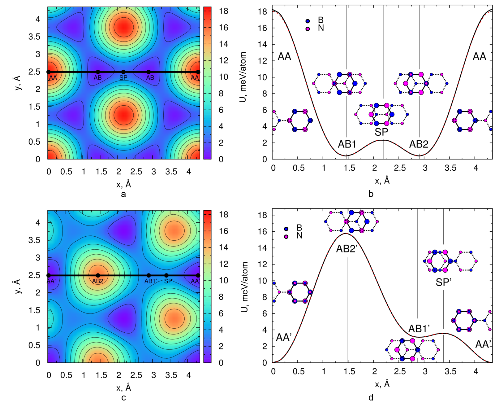
Let us now discuss the results of calculations of the potential energy surfaces for two orientations of h-BN layers in the simulation cell (Fig. 1). For h-BN layers aligned in the same direction (Fig. 1a and b), the potential surface of interlayer interaction energy is very similar to that of graphene layers, in agreement with previous calculations.55 The energy minima correspond to the AB stacking in which nitrogen (boron) atoms of the top layer are located on top of boron (nitrogen) atoms of the bottom layer and boron (nitrogen) atoms of the top layer are on top of hexagon centers. It is clear that at this relative orienation of the layers all configurations corresponding to the AB stacking with boron (AB2) or nitrogen (AB1) atoms of the top layer on top of the centers of the hexagons are equivalent. Shifting the layers by half of the bond length in the armchair direction (towards the nearest minimum) brings the systems to the saddle-point (SP) stacking which corresponds to the barrier to relative sliding of the layers. We find that this barrier is about 2 meV/atom (Tables 1 and 2), within the range reported for graphene 7, 61, 64, 59, 65, 66, 60 and close to the LMP2 value 2.5 meV/atom for h-BN.55 Shifting the layers by one and half of the bond length more in the armchair direction results in the AA stacking in which all atoms of the top layer are located on top of the equivalent atoms of the bottom layer and the interlayer interaction energy reaches its maximum for the given interlayer distance. The energy of the AA stacking relative to the AB one is about 18 meV/atom (Tables 1 and 2), close to the DFT data for graphene 7, 61, 64, 59, 65, 66, 60 and for bilayer55 and bulk49, 51, 55 h-BN as well as LMP2 values of about 20 meV/atom 55 for bilayer and bulk h-BN.
The potential energy surface for h-BN layers aligned in the opposite directions (Fig. 1c and d) is rather different from those for graphene and h-BN layers aligned in the same direction, in agreement with previous calculations.54, 55 In this case there are two types of inequivalent AB’ stackings. In the AB1(2)’ stacking all boron (nitrogen) atoms of the top layer are on top of boron (nitrogen) atoms of the bottom layer and the rest of atoms of the top layer are on top of hexagon centers. Also the interlayer interaction energy reaches its maximum for the given orientation at the AB2’ stacking, while the local minima correspond to the AB1’ stacking along with the AA’ stacking in which all nitrogen and boron atoms of the top layer are on top of boron and nitrogen atoms of the bottom layer, respectively. The saddle-point stacking corresponding to the barrier to relative sliding of the layers lies on the straight path between the nearest configurations corresponding to the AB1’ and AA’ but not in the middle (0.53 Å from AB1’ and 0.92 Å from AA’) since the minima are of different depth.
All the DFT methods predict that the energies of the AB, AB1’ and AA’ stackings are rather close and differ only by several meV/atom. However, the order of stability of this structures changes depending on the method and chosen interlayer distance.49, 51, 43, 54, 55, 57 Our results indicate that the most stable stacking both for h-BN bulk and bilayer is AA’ (Tables 1 and 2) and these results are consistent with the experimental observations for bulk h-BN28 as well as with the LMP2 calculations 55 and DFT calculations with account of nonlocal many-body dispersion (MBD) 57 for bilayer and bulk h-BN. The AB stacking is higher in energy only by 0.4 meV/atom and the relative energy of the AB1’ stacking is 3 meV/atom, in agreement with the LMP2 results 55 (Tables 1 and 2) and the experimental data 42 that both the AA’ and AB stackings are observed for bilayer h-BN. The AB1’ minima in our case are very shallow and are close in energy to the transition state SP’ for relative sliding of the layers. The corresponding barrier for transition from the AA’ to AB1’ stacking is 3.6 meV/atom, somewhat higher than in the case of h-BN layers aligned in the same direction.
| Stacking | vdW-DF2 | rPW86 (x) + LDA (c) | difference |
|---|---|---|---|
| AB1’ | 3.10 | 3.87 | -0.76 |
| AB2’ | 15.77 | 15.30 | 0.48 |
| SP’ | 3.57 | 4.08 | 0.51 |
| AB | 0.40 | 0.85 | -0.45 |
| SP | 2.32 | 2.68 | 0.36 |
| AA | 18.26 | 17.62 | 0.64 |
It should be also mentioned that switching the vdW contribution off (using only LDA correlation and rPW86 exchange 72) does not change the order of the symmetric stackings (Table 3). Their relative energies with respect to the AA’ stacking are changed by 0.4 - 0.8 meV/atom, which is within 5% of the magnitudes of corrugation of the potential energy surfaces both for h-BN layers aligned in the same and opposite directions. The analogous conclusion was made previously for graphene bilayer 66, 60, 59 and h-BN bilayer 54, 55, 57 for a set of functionals with the dispersion correction.
Another observation is that the calculated relative energies of different stackings for bilayer and bulk h-BN are nearly identical (Tables 1 and 2), in agreement with previous calculations for graphene.60, 61 The relative deviation is within 0.2 meV/atom, i.e. about 1% of the magnitudes of corrugation of the potential energy surfaces for h-BN layers aligned in the same and opposite directions, and can be explained by interaction of non-adjacent layers in the bulk material.
2.2 Approximation of potential energy surfaces
To approximate the potential energy surface of bilayer h-BN we consider the top layer as adsorbed on the bottom one and recall that the potential energy surface of an atom adsorbed on a 2D trigonal lattice can be approximated by the first Fourier harmonics as 58
| (1) |
where , , is the bond length and the point and corresponds to the case when the atom is located on top of one of the lattice atoms. In the case of h-BN, we should sum up interactions for boron atoms on the boron lattice (BB), nitrogen atoms on the nitrogen lattice (NN), boron atoms on the nitrogen lattice (BN) and nitrogen atoms on the boron lattice (NB). In the latter two contributions and . Then for h-BN layers aligned in the same direction we arrive at
| (2) |
where the point and corresponds to the AA stacking and . It is seen that corrugations of the potential energy surface of h-BN layers aligned in the same direction are described by a single parameter , which determines all physical properties related to interlayer interaction for h-BN materials with adjacent layers aligned in the same direction.
For h-BN layers aligned in the opposite directions,
| (3) |
where the point and corresponds to the AA’ stacking. In this case corrugations of the potential energy surface are described by two parameters and and these parameters are responsible for the properties of h-BN materials with adjacent layers aligned in the opposite directions.
The parameters of the approximation are found from the relative energies of the symmetric stackings AA’, AB1’, AB2’ and AB as
| (4) |
The values obtained are meV/atom, meV/atom and meV/atom and allow straightforward physical interpretation. The negative value of corresponds to the attraction of ions of different sign, while positive values of and are related to repulsion of ions of the same sign. The greater value of compared to is associated with the larger size of the boron ion as compared to the nitrogen one.87
In addition to corrugations of the potential energy surface for h-BN layers aligned in the opposite directions and relative energy of the co-aligned configuration, which are reproduced exactly, the approximation is very accurate in relative energies of the SP and AA stackings for h-BN layers aligned in the same direction (Fig. 1b and d). The magnitude of corrugation for this orientation of the layers according to the approximation is meV/atom, which is only 0.18 meV/atom or 1% smaller than the DFT value obtained. The barrier to relative sliding of the layers aligned in the same directions according to the approximation is meV/atom. This is only 0.05 meV/atom or 2.6% greater then the DFT value. The standard deviation of the approximated potential energy surfaces from the ones obtained by the DFT calculations for h-BN layers aligned in the same and opposite directions are 0.056 meV/atom and 0.014 meV/atom, respectively, which is within 0.3% of their magnitudes of corrugation.
We should note that the possibility to accurately approximate potential energy surfaces by expressions containing only the first Fourier harmonics has been previously demonstrated for interaction between graphene layers66, 60, 61, 88 and between carbon nanotube walls, both for infinite commensurate walls81, 89, 90, 91, 92 and in the case where corrugations of the potential surface are determined by the contribution of edges 93 or defects.81 Thus we can expect that analogous expressions can describe potential energy surfaces for other layered materials with the van der Waals interaction between layers or for translational motion of large molecules physically adsorbed on crystal surfaces.
It should be also pointed out that the expression given by eq. 2 for approximation of the potential energy surface for h-BN layers aligned in the same direction is exactly the same as the one for graphene.9, 10, 61, 59 The calculated barrier to relative sliding of h-BN layers aligned in the same direction and the magnitude of corrugation of the potential energy surface (Tables 1 and 2) are within the ranges reported for graphene 7, 61, 64, 59, 65, 66, 60. Therefore it can be expected that these materials have very similar physical properties. This is confirmed in section 3 by comparison of physical quantities estimated for h-BN on the basis of eq. 2 with the experimental data for graphene.
2.3 Mechanical properties of single-layer h-BN
To get the Young modulus and Poisson ratio of a single h-BN layer strains up to 0.8% in the armchair direction and up to 0.5% in the perpendicular zigzag direction have been considered. For each size of the unit cell, positions of atoms within the cell have been optimized using the quasi-Newton method 94 till the residual force of eV/Å. The energy dependence on the strain in the zigzag direction at a given strain in the armchair direction has been approximated by a parabola. The dependence of the energy corresponding to the parabola minimum on the elongation in the armchair direction gives the elastic constant J/m2 or Young modulus GPa, where Å is the interlayer distance in bulk h-BN, while the dependence of the position of the parabola minimum gives the Poisson ratio . These values are in excellent agreement with the experimental data for bulk h-BN of GPa and (Ref. 35) and are close to the DFT results for bulk h-BN of GPa, (Ref. 53), GPa, (Ref. 46) and for single-layer h-BN of J/m2, (Ref. 95) and 291 J/m2, (Ref. 96).
3 Properties related to interlayer interaction
As shown in the previos section, potential surfaces of interlayer interaction energy for h-BN layers aligned in the same and opposite directions can be approximated by relatively simple functions involving only one or two independent parameters (eqs. 2 and 3), respectively. Therefore all properties of h-BN related to interaction and relative motion of the layers are basically determined by these one or two parameters for the layers aligned in the same and opposite directions, respectively. Our DFT calculations demonstrate that interaction of non-adjacent layers in bulk h-BN has a weak influence on the potential energy surface so that the same parameters are responsible for physical behavior of bilayer, few-layer and bulk h-BN.
3.1 Shear mode frequency and shear modulus
The frequency of the shear mode in -layer and bulk () h-BN, in which adjacent layers slide rigidly in the opposite in-plane directions, is determined by the curvature of the potential energy surface in a given metastable state 61
| (5) |
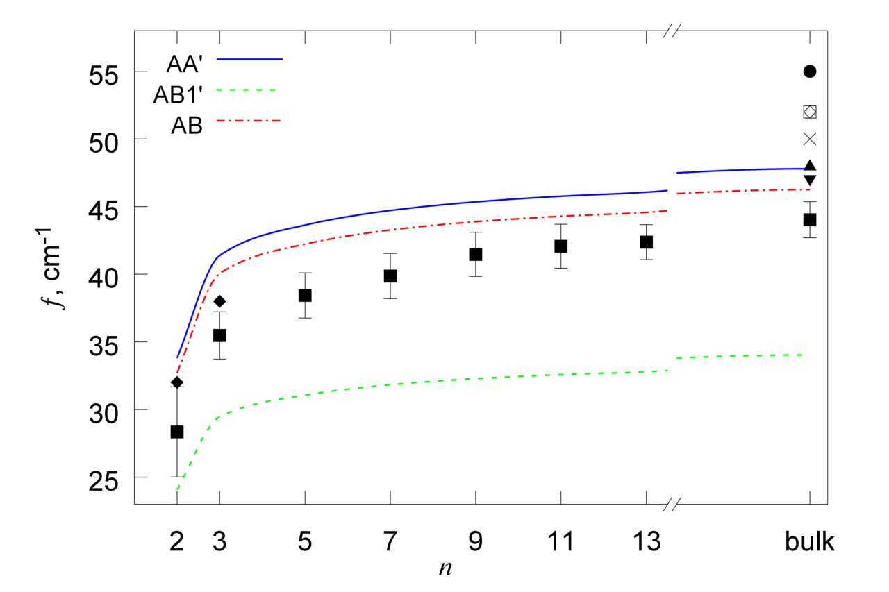
where for and for , and are masses of boron and nitrogen atoms, respectively, is an integer, is the bond length and we denote . Curvatures of the potential energy surfaces in the states corresponding to the AA’, AB1’ and AB stackings are described the parameters meV/atom, meV/atom and meV/atom. The corresponding shear mode frequencies as functions of the number of layers are shown in Fig. 2. The estimated shear mode frequency for the ground-state AA’ stacking of bulk h-BN is in good agreement with the experimental data37, 38 and results of previous DFT calculations46, 52, 53 (Fig. 2). The calculated dependences of the shear mode frequencies for the AA’ and AB stackings on the number of layers are similar to the experimental ones for graphene. 98, 97
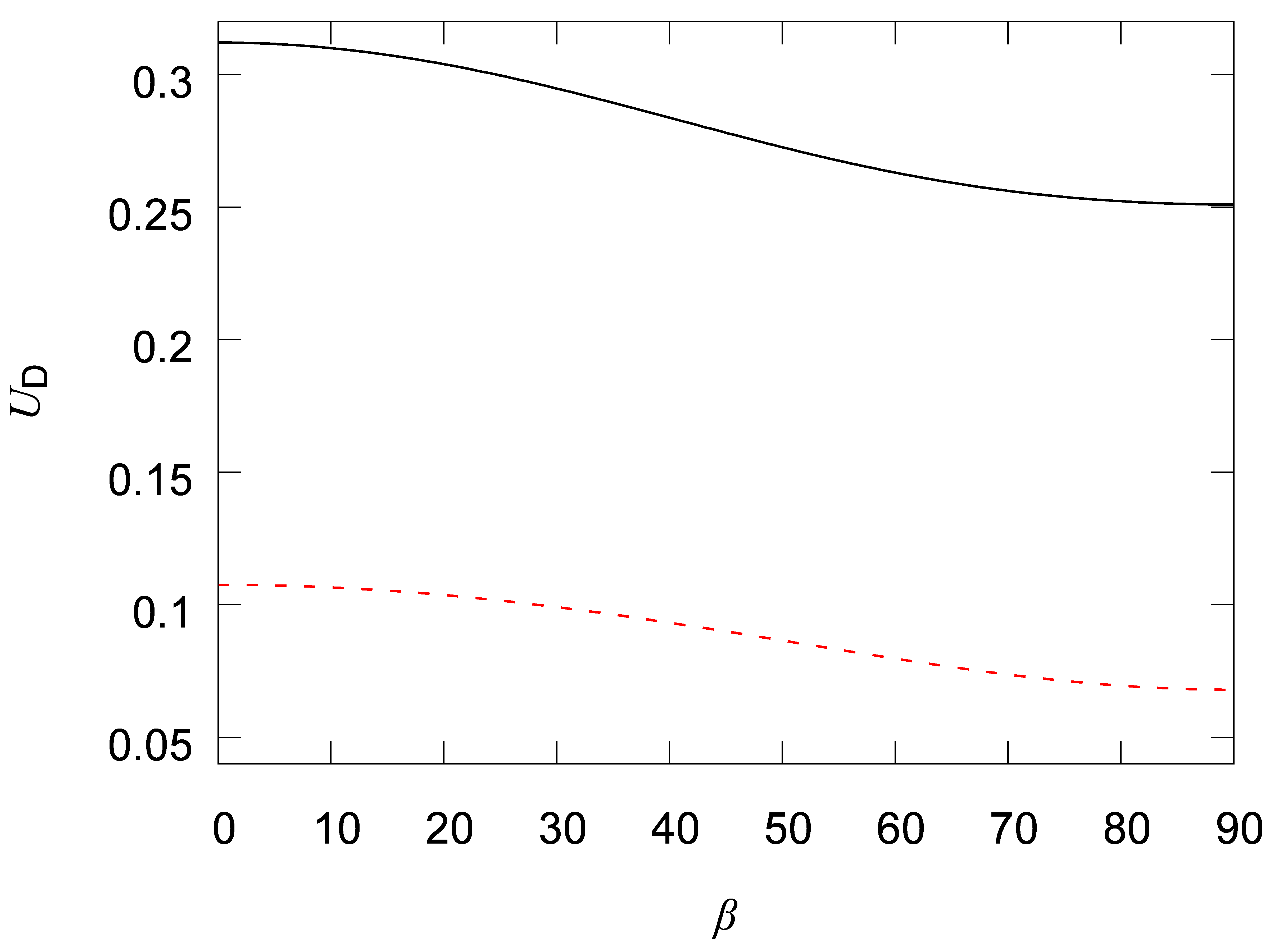
The curvature of the potential energy surface also determines the shear modulus, which is expected to weakly depend on the number of h-BN layers and can be estimated as
| (6) |
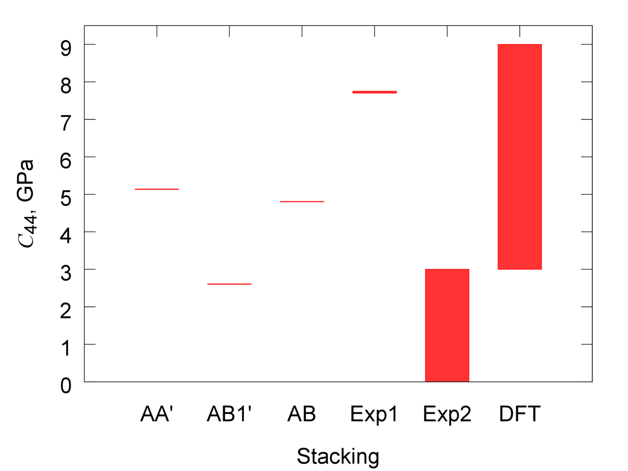
where is the area per atom in a h-BN layer and Å is the interlayer distance. The shear moduli obtained for different stackings of the layers are given in Fig. 3. It is seen that the result for the AA’ stacking is within the range of the experimental35, 99 and theoretical values53 for bulk h-BN.
3.2 Barrier to relative rotation of h-BN layers
The same as for graphene,9, 10 the potential energy surface of h-BN layers rotated to an incommensurate state should be smooth. Therefore the interaction energy in such states can be estimated as an average of the interaction energy (eqs. 2 and 3) over in-plane relative displacements of the layers in the commensurate states
| (7) |
Thus the barriers to relative rotation of h-BN layers from metastable states corresponding to the AA’, AB1’ and AB stackings are meV/atom, meV/atom and meV/atom, respectively. The values for the most stable AA’ and AB stackings are on the order of the data for graphene meV/atom (Ref. 61) and 4 meV/atom (Ref. 9, 10). The obtained expressions for the potential energy surface (eqs. 2 and 3) can be also used to estimate the barries to relative rotation of h-BN layers in configurations corresponding to Moiré patterns analogously to studies performed for graphene.100
3.3 Dislocations
Another manifestation of incommensurate states in two-dimensional layered materials is related to dislocations in stacking of the layers, which are observed when different parts of the system experience different relative shifts between the layers and correspond to incommensurate boundaries between commensurate domains. 7, 18, 19, 20, 21, 22, 23, 24, 25, 26 It has been demonstrated that such dislocations have a strong effect on the electronic22, 23, 24, 25, 27 and optical26 properties of graphene. The analysis of structure of dislocations in few-layer graphene by transmission electron microscopy has already helped to get an experimental estimate of the barrier to relative displacement of the layers.7 Along with the properties discussed above the formation energy and width of dislocations in bilayer h-BN can be obtained from the potential surface of interlayer interaction energy.63
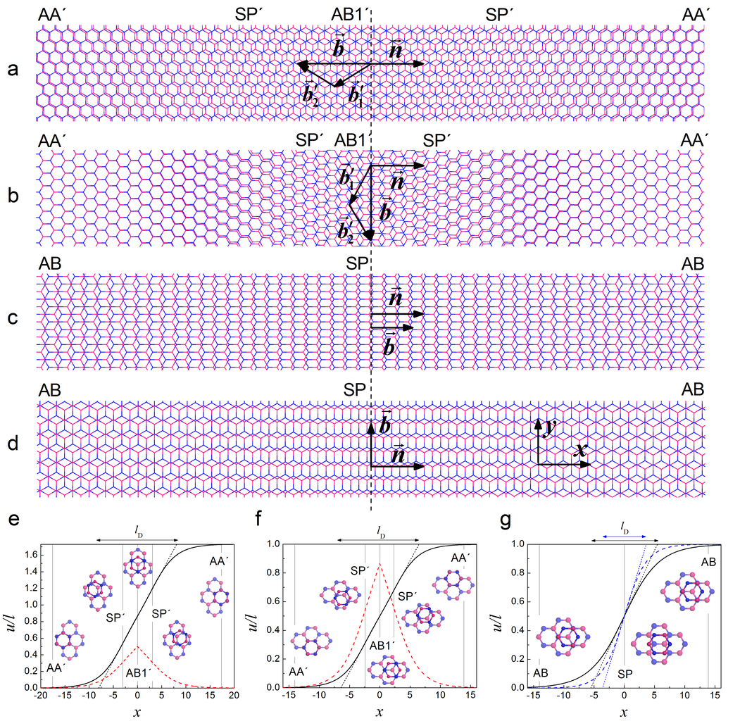
To consider dislocations in bilayer h-BN we follow the formalism of the two-chain Frenkel-Kontorova model,62 which was applied previously to study dislocations in double-walled carbon nanotubes62, 91 and graphene.63 Elementary dislocations in graphene correspond to partial dislocations with the Burgers vector equal in magnitude to the bond length.63, 7 Similar dislocations (, Fig. 4c,d) are also possible in h-BN layers aligned in the same direction as the potential surface of interlayer interaction in this case has degenerate energy minima AB1 and AB2 separated by the distance of one bond length (Fig. 1a). However, for h-BN layers aligned in the opposite directions, the AB1’ energy minima are rather shallow and are much higher in energy than the AA’ minima (Fig. 1c). Therefore in this case the minimal possible Burgers vector is equal in magnitude to the lattice constant (, Fig. 4a,b), i.e. the elementary dislocations are full. Both full dislocations in h-BN layers aligned in the opposite directions and partial dislocations in h-BN layers aligned in the same direction are considered below. It should be also noted that even for graphene theoretical estimates of the formation energy and width have been limited to the tensile dislocation with the Burger vector normal to the boundary between commensurate domains,63 though experimentally dislocations with different angles between the Burgers vector and boundary between commensurate domains have been observed.7, 19, 20, 21, 22, 24 Here we extend the Frenkel-Kontorova model to describe dislocations with the Burgers vector at an arbitrary angle to the normal to the boundary between commensurate domains. In particular, the results for shear dislocations (Fig. 4b,d), where the Burgers vector is parallel to the boundary between commensurate domains , are presented along with the results for tensile dislocations (Fig. 4a,c) with .
In the limit of large systems and low density of dislocations it can be assumed that dislocations are isolated. This means that the layers are commensurate at large distances from the dislocation center. Correspondingly, the boundary conditions for the relative displacement of atoms of the layers can be formulated as at and at , where is the coordinate along the normal to the boundary between commensurate domains and is the Burgers vector. According to the Frenkel-Kontorova model,62, 63 the formation energy of isolated dislocations per unit length is determined by the sum of excessive elastic and van der Waals interaction energies originating from the deformation and incommensurability of the layers, respectively,
| (8) |
where the axis is chosen along the boundary between commensurate domains, describes the strain across the boundary, is the van der Waals interaction energy per unit area relative to the deepest energy minimum for the given alignment of h-BN layers (the AB and AA’ stackings for the layers aligned in the same and opposite directions, respectively), and are the tensile and shear elastic constant of the layers, respectively, is the elastic constant under uniaxial stress and is the Poisson ratio. Introducing the coefficient in the tensile elastic constant we take into account that the tensile strain is kept zero in the direction along the boundary between commensurate domains (see also Ref. 7). In the absence of an external load, one of the layers in the tensile dislocation is stretched in the direction accross the boundary, while the other one is compressed.63 Therefore in the perpendicular direction they tend to compress and stretch, respectively. The interlayer interaction, however, keeps the layers commensurate in the latter direction, providing the vanishing tensile strain along the boundary in the regions far from boundary crossings. It should be also noted that the coefficient is only slightly different from unity and gives corrections to the formation energy and characteristic width of dislocations within 2%.
The dislocation path, i.e. the dependence of the relative displacement of h-BN layers on the coordinate in the direction perpendicular to the boundary between commensurate domains (Fig. 4e-g) that minimizes the formation energy (eq. 8), should satisfy the Euler-Lagrange equations
| (9) |
This means that the dislocation path is the same as the trajectory of a particle on the inverse potential energy surface with the fixed initial and final positions corresponding to the deepest energy minima of the original potential energy surface. It should be noted that the "particle mass" is anisotropic and equal to and in the directions along and across the boundary between commensurate domains, respectively.
For partial dislocations in h-BN layers aligned in the same direction (Fig. 4c,d), the straight line between the adjacent AB minima (Fig. 1a) corresponding to the minimum energy path satisfies eq. 9 and thus gives exactly the dislocation path. For full dislocations in h-BN layers aligned in the opposite directions (Fig. 4a,b), the solution of eq. 9 cannot be found analytically. Moreover, this solution should depend on the angle between the Burgers vector and the boundary between commensurate domains. However, it is clear that strong scattering introduced by rapidly changing potential at slopes of the AB2’ hill (Fig. 1c) should be avoided. Therefore we assume that the path of full dislocations in h-BN layers aligned in the opposite directions is also roughly described by the minimum energy path AA’ – AB1’ – AA’ consisting of two straight lines at the angle to each other. More accurate approximations of the dislocation path give a correction to the formation energy within 10%.
Integration of the Euler-Lagrange equations (eq. 9) provides the analogue of the energy conservation law
| (10) |
Here we use that the integration constant is zero for isolated dislocations63 and denote , where is the angle between the direction of the dislocation path and normal to the boundary between commensurate domains. Taking into account eq. 10, the formation energy of dislocations per unit length (eq. 8) can then be expressed as
| (11) |
Let us first consider partial dislocations in h-BN layers aligned in the same direction (Fig. 4c,d). In these dislocations, atoms are displaced along straight lines, and changes from 0 to . According to eq. 11, the formation energy of partial dislocations is
| (12) |
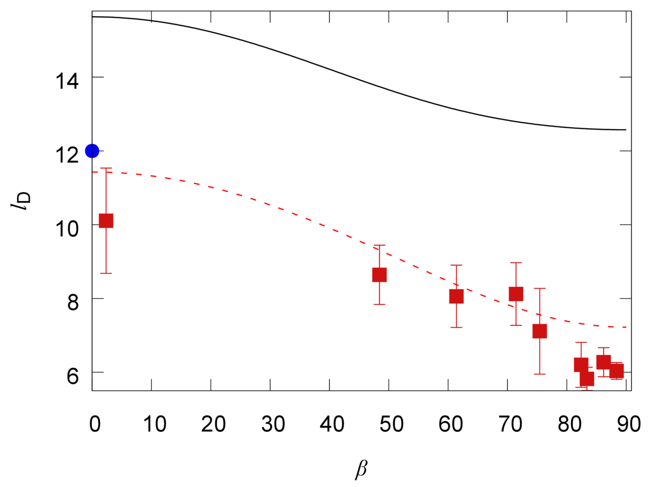
where we approximate the interlayer interaction energy along the minimum energy path on the basis of eq. 2. Fig. 5 demonstrates that the formation energy per unit length is maximal for tensile dislocations (Fig. 4c) and minimal for shear dislocations (Fig. 4d). Such dislocations correspond to the boundaries between commensurate domains in the zigzag and armchair directions, respectively. The estimated formation energies for h-BN layers aligned in the same direction (Fig. 5) are on the order of the value predicted for partial tensile dislocations in bilayer graphene of 0.12 eV/Å (Ref. 63).
Based on the approximation of the interlayer interaction energy along the minimum energy path by the cosine function and eq. 10, it was shown analytically that partial dislocations are described by a soliton with a relatively short incommensurate region separating commensurate domains.63 Though in the present paper we use eq. 2 to approximate the potential energy surface of h-BN layers aligned in the same direction, the calculated path of partial dislocations is very close to the analytical solution (Fig. 4g). Since the slope of the dependence of displacement on position across the boundary is nearly constant around the dislocation center and close to the maximum value , the dislocation width can be defined in the way similar to the analytical solution
| (13) |
where is the barrier to relative sliding of the layers. It is clear that the dependence of the dislocation width on the angle between the Burgers vector and normal to the boundary between commensurate domains is the same as that of the formation energy (eq. 12). In particular, the width of shear dislocations is smaller than the width of tensile ones (Fig. 6). The dependence of the formation energy and width of partial dislocations on the angle between the Burgers vector and boundary between commensurate domains is determined only by the Poisson ratio and should approximately hold for any hexagonal 2D crystals or heterostructures consisting of the layers with slightly different lattice constants where partial dislocations are possible. In particular, the calculated angular dependence of the dislocation width is in good agreement with experimentally measured values for graphene7, 20, 21 ranging from 11 nm for tensile dislocations to 6 – 7 nm for shear dislocations (Fig. 6). The calculated width of partial tensile dislocations is also on the order of the DFT estimate for graphene63 of 12 nm.
In the case of full dislocations in h-BN layers aligned in the opposite directions (Fig. 4a,b), it is needed to take into account two contributions from the straight pieces of the dislocation path at angles and to the normal to the boundary between commensurate domains. This can be done by a simple substitution of by in eqs. 12 and 13. All the conclusions made above for partial dislocations are also valid for full ones (Figs. 5 and 6) with the only difference that full tensile and shear dislocations correspond to the boundaries between commensurate domains in the armchair and zigzag directions, respectively (Fig. 4a,b), opposite to the case of partial dislocations. It should be especially emphasized that according to Figs. 4e–g, both for partial and full dislocations the slope is nearly constant for distances from the dislocation center comparable to the dislocation width. This gives the possibility of accurate measurements of the dislocation width and, consequently, of experimental estimation of the barrier to relative sliding of h-BN layers by transmission electron microscopy analysis of stacking at the boundary between commensurate domains in the same way as it was done for graphene.7
4 Conclusions
DFT calculations of the potential surface of interlayer interaction energy at relative in-plane displacement of h-BN layers have been performed using the vdW-DF2 functional.72 According to these results, the ground state corresponds to the AA’ stacking of the layers aligned in the opposite directions. However, the optimal AB stacking for the layers aligned in the same direction is only 0.4 meV/atom less favourable, in agreement with the experimental observation42 of both AB and AA’ stackings for bilayer h-BN. The magnitudes of corrugation of the potential energy surfaces are about 18 meV/atom and 16 meV/atom for the layers aligned in the same and opposite directions, respectively. The barriers to relative motion of the layers aligned in the same and opposite directions are 2 meV/atom and 3.6 meV/atom, respectively, in close agreement with LMP2 calculations.55 Almost identical results are obtained for bilayer and bulk h-BN, indicating that interactions between non-adjacent layers have a weak effect on the characteristics of the potential energy surface (1% of the magnitude of corrugation). The contribution of vdW interactions into these quantities is also small (within 5% of the magnitude of corrugation) and comparable to that in previous studies for h-BN 54, 55 and graphene.66, 60, 59
It is shown that the calculated potential surfaces of interlayer interaction energy for h-BN layers aligned in the same and opposite directions can be fitted by simple expressions containing only the first components of Fourier expansions determined by symmetry of the layers. Analogous approximations have been suggested previously for graphene bilayer66, 60, 61, 88 and double-walled carbon nanotubes 81, 89, 90, 91, 92, 93 based both on DFT calculations and semi-empirical potentials. Thus it can be expected that for other layered materials the potential surface of interlayer interaction energy can be also reproduced closely by the first Fourier components determined by symmetry.
Recently a concept of the registry index surface was proposed to predict qualitative features of the potential surface of interlayer interaction energy of h-BN bilayer.54 The expressions introduced here give the possibility to reproduce the shape and quantitative characteristics of the potential energy surface of h-BN bilayer and can be useful for multiscale simulations of such phenomena as atomic-scale slip-stick motion of a h-BN flake attached to STM tip on the h-BN surface, diffusion of a h-BN flake on the h-BN surface and formation of stacking dislocations in h-BN bilayer (analogous to multiscale simulations of the phenomena observed for graphene 4, 5, 6, 8, 9, 10, 7, 18, 19, 20, 21, 22, 23, 24, 25, 26).
According to the proposed approximation, a set of physical properties of h-BN materials related to relative motion of the layers are determined by only one or two independent parameters for the layers aligned in the same and opposite directions, respectively. Namely, the shear mode frequency, shear modulus and barrier to relative rotation of the layers have been estimated for bilayer and bulk h-BN in different stackings. The possibility of partial and full dislocations in stacking of the layers is suggested for h-BN layers aligned in the same and opposite directions, respectively. Their width and formation energy are governed by the same parameters of the potential energy surface. In particular, it is shown that a simple link exists between the dislocation width and barrier to relative sliding of the layers , where the coefficient is determined by the elastic properties of the layers. Experimental measurements of the dislocation width, shear mode frequency or shear modulus can help to refine the parameters of the functions approximating the potential surfaces of interlayer interaction energy in h-BN and to obtain the barriers and other characteristics of these surfaces in the same way as it was done for graphene.7, 61
5 Acknowledgement
Authors acknowledge the Russian Foundation of Basic Research (14-02-00739-a) and computational time on the Supercomputing Center of Lomonosov Moscow State University and the Multipurpose Computing Complex NRC "Kurchatov Institute". IL acknowledges financial support from the Marie Curie International Incoming Fellowship (Grant Agreement PIIF-GA-2012-326435 RespSpatDisp), EU-H2020 project "MOSTOPHOS" (n. 646259) and Grupos Consolidados del Gobierno Vasco (IT-578-13).
References
- Rong and Kuiper 1993 Z. Y. Rong and P. Kuiper, Phys. Rev. B, 1993, 48, 17427–17431.
- Gan et al. 2003 Y. Gan, W. Chu and L. Qiao, Surf. Sci., 2003, 539, 120–128.
- Warner et al. 2009 J. H. Warner, M. H. Rümmeli, T. Gemming, B. Büchner and G. A. D. Briggs, Nano Lett., 2009, 9, 102–106.
- Dienwiebel et al. 2004 M. Dienwiebel, G. S. Verhoeven, N. Pradeep, J. W. M. Frenken, J. A. Heimberg and H. W. Zandbergen, Phys. Rev. Lett., 2004, 92, 126101.
- Dienwiebel et al. 2005 M. Dienwiebel, N. Pradeep, G. S. Verhoeven, H. W. Zandbergen and J. W. M. Frenken, Surf. Sci., 2005, 576, 197–211.
- Filippov et al. 2008 A. E. Filippov, M. Dienwiebel, J. W. M. Frenken, J. Klafter and M. Urbakh, Phys. Rev. Lett., 2008, 100, 046102.
- Alden et al. 2013 J. S. Alden, A. W. Tsen, P. Y. Huang, R. Hovden, L. Brown, J. Park, D. A. Muller and P. L. McEuen, PNAS, 2013, 110, 11256–11260.
- Zheng et al. 2008 Q. Zheng, B. Jiang, S. Liu, Y. Weng, L. Lu, Q. Xue, J. Zhu, Q. Jiang, S. Wang and L. Peng, Phys. Rev. Lett., 2008, 100, 067205.
- Lebedeva et al. 2010 I. V. Lebedeva, A. A. Knizhnik, A. M. Popov, O. V. Ershova, Y. E. Lozovik and B. V. Potapkin, Phys. Rev. B, 2010, 82, 155460.
- Lebedeva et al. 2011 I. V. Lebedeva, A. A. Knizhnik, A. M. Popov, O. V. Ershova, Y. E. Lozovik and B. V. Potapkin, J. Chem. Phys., 2011, 134, 104505.
- Bistritzer and MacDonald 2010 R. Bistritzer and A. H. MacDonald, Phys. Rev. B, 2010, 81, 245412.
- Bistritzer and MacDonald 2011 R. Bistritzer and A. H. MacDonald, PNAS, 2011, 108, 12233–12237.
- Poklonski et al. 2013 N. A. Poklonski, A. I. Siahlo, S. A. Vyrko, A. M. Popov, Y. E. Lozovik, I. V. Lebedeva and A. A. Knizhnik, J. Comp. Theor. Nanosci., 2013, 10, 141–146.
- Lam et al. 2009 K.-T. Lam, C. Lee and G. Liang, Appl. Phys. Lett., 2009, 95, 143107.
- Qian et al. 2012 Y. Qian, K.-T. Lam, C. Lee and G. Liang, Carbon, 2012, 50, 1659–1666.
- Zheng et al. 2012 J. Zheng, P. Guo, Z. Ren, Z. Zhenyi, J. Bai and Z. Zhang, Appl. Phys. Lett., 2012, 101, 083101.
- Paulla and Farajian 2013 K. K. Paulla and A. A. Farajian, J. Phys.: Cond. Matter, 2013, 25, 115303.
- Brown et al. 2012 L. Brown, R. Hovden, P. Huang, M. Wojcik, D. A. Muller and J. Park, Nano Lett., 2012, 12, 1609–1615.
- Butz et al. 2013 B. Butz, C. Dolle, F. Niekiel, K. Weber, D. Waldmann, H. B. Weber, B. Meyer and E. Spiecker, Nature, 2013, 505, 533–537.
- Lin et al. 2013 J. Lin, W. Fang, W. Zhou, A. R. Lupini, J. C. Idrobo, J. Kong, S. J. Pennycook and S. T. Pantelides, Nano Lett., 2013, 13, 3262–3268.
- Yankowitz et al. 2014 M. Yankowitz, J. I.-J. Wang, A. G. Birdwell, Y.-A. Chen, K. Watanabe, T. Taniguchi, P. Jacquod, P. San-Jose, P. Jarillo-Herrero and B. J. LeRoy, Nat. Mater., 2014, 13, 786–789.
- Hattendorf et al. 2013 S. Hattendorf, A. Georgi, M. Liebmann and M. Morgenstern, Surf. Sci., 2013, 610, 53–58.
- San-Jose et al. 2014 P. San-Jose, R. V. Gorbachev, A. K. Geim, K. S. Novoselov and F. Guinea, Nano Lett., 2014, 14, 2052–2057.
- Lalmi et al. 2014 B. Lalmi, J. C. Girard, E. Pallecchi, M. Silly, C. David, S. Latil, F. Sirotti and A. Ouerghi, Sci. Rep., 2014, 4, 4066.
- Benameur et al. 2015 M. M. Benameur, F. Gargiulo, S. Manzeli, G. Autès, M. Tosun, O. V. Yazyev and A. Kis, Nat. Comm., 2015, 6, 8582.
- Gong et al. 2013 L. Gong, R. J. Young, I. A. Kinloch, S. J. Haigh, J. H. Warner, J. A. Hinks, Z. Xu, L. Li, F. Ding, I. Riaz, R. Jalil and K. S. Novoselov, ACS Nano, 2013, 7, 7287–7294.
- Koshino 2013 M. Koshino, Phys. Rev. B, 2013, 88, 115409.
- Pease 1950 R. S. Pease, Nature, 1950, 165, 722–723.
- Pease 1952 R. S. Pease, Acta Crystallographica, 1952, 5, 356–361.
- Lynch and Drickamer 1966 R. W. Lynch and H. G. Drickamer, J. Chem. Phys., 1966, 44, 181.
- Solozhenko et al. 1995 V. L. Solozhenko, G. Will and F. Elf, Solid State Communications, 1995, 96, 1–3.
- Solozhenko and Peun 1997 V. L. Solozhenko and T. Peun, J. Phys. Chem. Solids, 1997, 58, 1321–1323.
- Solozhenko et al. 2001 V. L. Solozhenko, A. G. Lazarenko, J.-P. Petitet and A. V. Kanaev, J. Phys. Chem. Solids, 2001, 62, 1331–1334.
- Paszkowicz et al. 2002 W. Paszkowicz, J. B. Pelka, M. Knapp, T. Szyszko and S. Podsiadlo, Appl. Phys. A, 2002, 75, 431–435.
- Bosak et al. 2006 A. Bosak, J. Serrano, M. Krisch, K. Watanabe, T. Taniguchi and H. Kanda, Phys. Rev. B, 2006, 73, 041402.
- Fuchizaki et al. 2008 K. Fuchizaki, T. Nakamichi, H. Saitoh and Y. Katayama, Solid State Communications, 2008, 148, 390–394.
- Nemanich et al. 1981 R. J. Nemanich, S. A. Solin and R. M. Martin, Phys. Rev. B, 1981, 23, 6348–6356.
- Reich et al. 2005 S. Reich, A. C. Ferrari, R. Arenal, A. Loiseau, I. Bello and J. Robertson, Phys. Rev. B, 2005, 71, 205201.
- Marini et al. 2006 A. Marini, P. García-González and A. Rubio, Phys. Rev. Lett., 2006, 96, 136404.
- Li et al. 2009 C. Li, Y. Bando, C. Zhi, Y. Huang and D. Golberg, Nanotechnology, 2009, 20, 385707.
- Zhi et al. 2009 C. Zhi, Y. Bando, C. Tang, H. Kuwahara and D. Golberg, Adv. Mater., 2009, 21, 2889 – 2893.
- Warner et al. 2010 J. H. Warner, M. H. Rümmeli, A. Bachmatiuk and B. Büchner, ACS Nano, 2010, 4, 1299–1304.
- Nag et al. 2010 A. Nag, K. Raidongia, K. P. S. S. Hembram, R. Datta, U. V. Waghmare and C. N. R. Rao, ACS Nano, 2010, 4, 1539–1544.
- Albe 1997 K. Albe, Phys. Rev. B, 1997, 55, 6203–6210.
- Kern et al. 1999 G. Kern, G. Kresse and J. Hafner, Phys. Rev. B, 1999, 59, 8551–8559.
- Ohba et al. 2001 N. Ohba, K. Miwa, N. Nagasako and A. Fukumoto, Phys. Rev. B, 2001, 63, 115207.
- Janotti et al. 2001 A. Janotti, S.-H. Wei and D. J. Singh, Phys. Rev. B, 2001, 64, 174107.
- Rydberg et al. 2003 H. Rydberg, M. Dion, N. Jacobson, E. Schröder, P. Hyldgaard, S. I. Simak, D. C. Langreth and B. I. Lundqvist, Phys. Rev. Lett., 2003, 91, 126402.
- Liu et al. 2003 L. Liu, Y. P. Feng and Z. X. Shen, Phys. Rev. B, 2003, 68, 104102.
- Tohei et al. 2006 T. Tohei, A. Kuwabara, F. Oba and I. Tanaka, Phys. Rev. B, 2006, 73, 064304.
- Ooi et al. 2006 N. Ooi, V. Rajan, J. Gottlieb, Y. Catherine and J. B. Adams, Modelling Simul. Mater. Sci. Eng., 2006, 14, 515–535.
- Serrano et al. 2007 J. Serrano, A. Bosak, R. Arenal, M. Krisch, K. Watanabe, T. Taniguchi, H. Kanda, A. Rubio and L. Wirtz, Phys. Rev. Lett., 2007, 98, 095503.
- Hamdi and Meskini 2010 I. Hamdi and N. Meskini, Physica B, 2010, 405, 2785–2794.
- Marom et al. 2010 N. Marom, J. Bernstein, J. Garel, A. Tkatchenko, E. Joselevich, L. Kronik and O. Hod, Phys. Rev. Lett., 2010, 105, 046801.
- Constantinescu et al. 2013 G. Constantinescu, A. Kuc and T. Heine, Phys. Rev. Lett., 2013, 111, 036104.
- Hsing et al. 2014 C.-R. Hsing, C. Cheng, J.-P. Chou, C.-M. Chang and C.-M. Wei, New J. Phys., 2014, 16, 113015.
- Gao and Tkatchenko 2015 W. Gao and A. Tkatchenko, Phys. Rev. Lett., 2015, 114, 096101.
- Verhoeven et al. 2004 G. S. Verhoeven, M. Dienwiebel and J. W. M. Frenken, Phys. Rev. B, 2004, 70, 165418.
- Reguzzoni et al. 2012 M. Reguzzoni, A. Fasolino, E. Molinari and M. C. Righi, Phys. Rev. B, 2012, 86, 245434.
- Lebedeva et al. 2011 I. V. Lebedeva, A. A. Knizhnik, A. M. Popov, Y. E. Lozovik and B. V. Potapkin, Phys. Chem. Chem. Phys., 2011, 13, 5687–5695.
- Popov et al. 2012 A. M. Popov, I. V. Lebedeva, A. A. Knizhnik, Y. E. Lozovik and B. V. Potapkin, Chem. Phys. Lett., 2012, 536, 82–86.
- Bichoutskaia et al. 2006 E. Bichoutskaia, M. I. Heggie, Y. E. Lozovik and A. M. Popov, Fullerenes, Nanotubes, Carbon Nanostruct., 2006, 14, 131–140.
- Popov et al. 2011 A. M. Popov, I. V. Lebedeva, A. A. Knizhnik, Y. E. Lozovik and B. V. Potapkin, Phys. Rev. B, 2011, 84, 045404.
- Kolmogorov and Crespi 2005 A. N. Kolmogorov and V. H. Crespi, Phys. Rev. B, 2005, 71, 235415.
- Aoki and Amawashi 2007 M. Aoki and H. Amawashi, Solid State Communications, 2007, 142, 123–127.
- Ershova et al. 2010 O. V. Ershova, T. C. Lillestolen and E. Bichoutskaia, Phys. Chem. Chem. Phys., 2010, 12, 6483–6491.
- Dion et al. 2004 M. Dion, H. Rydberg, E. Schröder, D. C. Langreth and B. I. Lundqvist, Phys. Rev. Lett., 2004, 92, 246401.
- Girifalco and Lad 1956 L. A. Girifalco and R. A. Lad, J. Chem. Phys., 1956, 25, 693–696.
- Benedict et al. 1998 L. X. Benedict, N. G. Chopra, M. L. Cohen, A. Zettl, S. G. Louie and V. H. Crespi, Chem. Phys. Lett., 1998, 286, 490–496.
- Zacharia et al. 2004 R. Zacharia, H. Ulbricht and T. Hertel, Phys. Rev. B, 2004, 69, 155406.
- Liu et al. 2012 Z. Liu, J. Z. Liu, Y. Cheng, Z. Li, L. Wang and Q. Zheng, Phys. Rev. B, 2012, 85, 205418.
- Lee et al. 2010 K. Lee, E. D. Murray, L. Kong, B. I. Lundqvist and D. C. Langreth, Phys. Rev. B, 2010, 82, 081101.
- Dean et al. 2010 C. R. Dean, A. F. Young, I. Meric, C. Lee, L. Wang, S. Sorgenfrei, K. Watanabe, T. Taniguchi, P. Kim, K. L. Shepard and J. Hone, Nature Nanotechnol., 2010, 5, 722–726.
- Ponomarenko et al. 2011 L. A. Ponomarenko, A. K. Geim, A. A. Zhukov, R. Jalil, S. V. Morozov, K. S. Novoselov, I. V. Grigorieva, E. H. Hill, V. V. Cheianov, V. I. Fal’ko, K. Watanabe, T. Taniguchi and R. V. Gorbachev, Nature Phys., 2011, 7, 958–961.
- Britnell et al. 2012 L. Britnell, R. V. Gorbachev, R. Jalil, B. D. Belle, F. Schedin, A. Mishchenko, T. Georgiou, M. I. Katsnelson, L. Eaves, S. V. Morozov, N. M. R. Peres, J. Leist, A. K. Geim, K. S. Novoselov and L. A. Ponomarenko, Science, 2012, 335, 947–950.
- Woods et al. 2014 C. R. Woods, L. Britnell, A. Eckmann, R. S. Ma, J. C. Lu, H. M. Guo, X. Lin, G. L. Yu, Y. Cao, R. V. Gorbachev, A. V. Kretinin, J. Park, L. A. Ponomarenko, M. I. Katsnelson, Y. N. Gornostyrev, K. Watanabe, T. Taniguchi, C. Casiraghi, H.-J. Gao, A. K. Geim and K. S. Novoselov, Nature Physics, 2014, 10, 451–456.
- Geim and Grigorieva 2013 A. K. Geim and I. V. Grigorieva, Nature, 2013, 499, 419–425.
- Kresse and Furthmüller 1996 G. Kresse and J. Furthmüller, Phys. Rev. B, 1996, 54, 11169–11186.
- Kresse and Joubert 1999 G. Kresse and D. Joubert, Phys. Rev. B, 1999, 59, 1758–1775.
- Monkhorst and Pack 1976 H. J. Monkhorst and J. D. Pack, Phys. Rev. B, 1976, 13, 5188–5192.
- Belikov et al. 2004 A. V. Belikov, Y. E. Lozovik, A. G. Nikolaev and A. M. Popov, Chem. Phys. Lett., 2004, 385, 72–78.
- Lozovik and Popov 2000 Y. E. Lozovik and A. M. Popov, Chem. Phys. Lett., 2000, 328, 355–362.
- Lozovik and Popov 2002 Y. E. Lozovik and A. M. Popov, Phys. Solid State, 2002, 44, 186–194.
- Grimme 2006 S. Grimme, J. Comp. Chem., 2006, 27, 1787–1799.
- Grimme et al. 2010 S. Grimme, J. Antony, S. Ehrlich and H. Krieg, J. Chem. Phys, 2010, 132, 154104.
- Popov et al. 2013 A. M. Popov, I. V. Lebedeva, A. A. Knizhnik, Y. E. Lozovik, B. V. Potapkin, N. A. Poklonski, A. I. Siahlo and S. A. Vyrko, J. Chem. Phys., 2013, 139, 154705.
- Huheey et al. 1993 J. E. Huheey, E. A. Keiter and R. L. Keiter, Inorganic Chemistry : Principles of Structure and Reactivity (4th Edition), HarperCollins, New York, USA, 1993.
- Lebedeva et al. 2012 I. V. Lebedeva, A. A. Knizhnik, A. M. Popov, Y. E. Lozovik and B. V. Potapkin, Physica E, 2012, 44, 949–954.
- Bichoutskaia et al. 2005 E. Bichoutskaia, A. M. Popov, A. El-Barbary, M. I. Heggie and Y. E. Lozovik, Phys. Rev. B, 2005, 71, 113403.
- Bichoutskaia et al. 2009 E. Bichoutskaia, A. M. Popov, Y. E. Lozovik, O. V. Ershova, I. V. Lebedeva and A. A. Knizhnik, Phys. Rev. B, 2009, 80, 165427.
- Popov et al. 2009 A. M. Popov, Y. E. Lozovik, A. S. Sobennikov and A. A. Knizhnik, JETP, 2009, 108, 621–628.
- Popov et al. 2012 A. M. Popov, I. V. Lebedeva and A. A. Knizhnik, Appl. Phys. Lett., 2012, 100, 173101.
- Popov et al. 2013 A. M. Popov, I. V. Lebedeva, A. A. Knizhnik, Y. E. Lozovik and B. V. Potapkin, J. Chem. Phys., 2013, 138, 024703.
- Pulay 1980 P. Pulay, Chem. Phys. Lett., 1980, 73, 393–398.
- Peng et al. 2012 Q. Peng, W. Ji and S. De, Comp. Mater. Sci., 2012, 56, 11–17.
- Duerloo et al. 2012 K.-A. N. Duerloo, M. T. Ong and E. J. Reed, J. Phys. Chem. Lett., 2012, 3, 2871–2876.
- Boschetto et al. 2013 D. Boschetto, L. Malard, C. H. Lui, K. F. Mak, Z. Li, H. Yan and T. F. Heinz, Nano Lett., 2013, 13, 4620–4623.
- Tan et al. 2012 P. H. Tan, W. P. Han, W. J. Zhao, Z. H. Wu, K. Chang, H. Wang, Y. F. Wang, N. Bonini, N. Marzari, N. Pugno, G. Savini, A. Lombardo and A. C. Ferrari, Nat. Mater., 2012, 11, 294–300.
- Duclaux et al. 1992 L. Duclaux, B. Nysten, J.-P. Issi and A. W. Moore, Phys. Rev. B, 1992, 46, 3362–3367.
- Xu et al. 2013 Z. Xu, X. Li, B. I. Yakobson and F. Ding, Nanoscale, 2013, 5, 6736–6741.