Simulation and performance of an artificial retina for MHz track reconstruction
Abstract
We present the results of a detailed simulation of the artificial retina pattern-recognition algorithm, designed to reconstruct events with hundreds of charged-particle tracks in pixel and silicon detectors at LHCb with LHC crossing frequency of . Performances of the artificial retina algorithm are assessed using the official Monte Carlo samples of the LHCb experiment. We found performances for the retina pattern-recognition algorithm comparable with the full LHCb reconstruction algorithm.
keywords:
Pattern recognition; Trigger algorithms1 Introduction
Higher LHC energy and luminosity increase the challenge of data acquisition and event reconstruction in the LHC experiments. The large number of interaction for bunch crossing (pile-up) greatly reduce the discriminating power of usual signatures, such as the high transverse momentum leptons or the high transverse missing energy. Therefore real-time track reconstruction is needed to quickly select potentially interesting events for higher level of processing. Performing such a task at the LHC crossing rate is a major challenge because of the large combinatorial and the size of the associated information flow and requires unprecedented massively parallel pattern-recognition algorithms. For this purpose we design and test a neurobiology-inspired pattern-recognition algorithm well suited for such a scope: the artificial retina algorithm.
2 An artificial retina algorithm
The original idea of an artificial retina tracking algorithm was inspired by the mechanism of visual receptive fields in the mammals eye [1]. Experimental studies have shown neurons tuned to recognize a specific shape on specific region of the retina (“receptive field”) [2, 3]. The strength of the response of each neuron to a stimulus is proportional to how close the shape of the stimulus is to the shape for which the neuron is tuned to. All neurons react to a stimulus, each with different strength, and the brain obtains a precise information of the received stimulus performing some sort of interpolation between the responses of neurons.
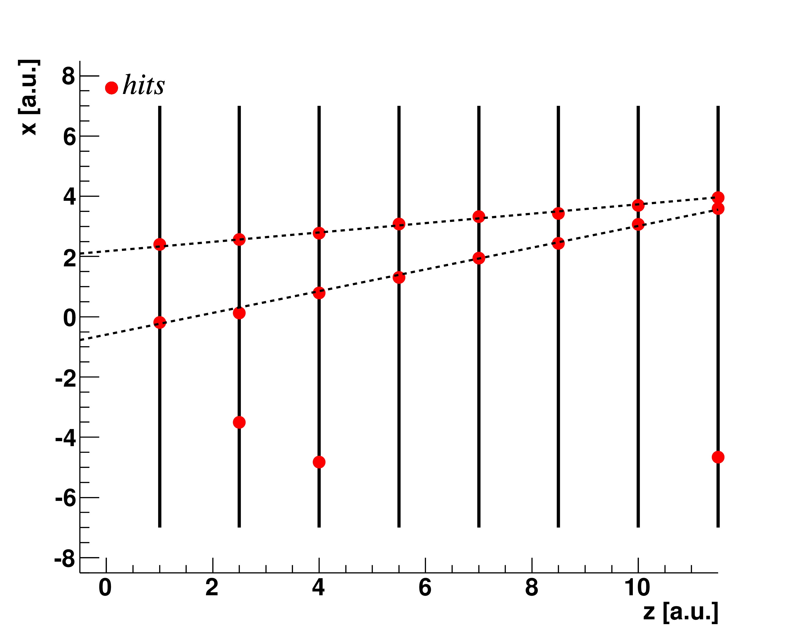
The retina concepts can be geared toward track reconstruction. Assuming a tracking detector made by a set of parallel layers, providing the measurement of a single spatial coordinate , and a detector volume without any magnetic field. Thus trajectories of charged particles are straight lines, intersecting detector layers, and are identified by two parameters, e. g. , where is the angular coefficient and is the intersection with the -axis in the -plane. We discretize the space of track parameters, , into cells, representing the receptive fields of the visual system. The centre of each cell identifies a track in the detector space, that intersects detector layers in spatial points that we call receptors. Therefore each -cell of the parameter space corresponds to a set of receptors , where runs over the detector layers, as shown in figure 1. This procedure is called detector mapping and it is done for all the cells of the track parameter space, covering all the detector acceptance.

For each incoming hit, the algorithm computes the excitation intensity, i. e. the response of the receptive field, of each -cell as follows:
| (1) |
using the distance
| (2) |
where is the -th hits on the detector layer , while is a parameter of the retina algorithm, that it can be adjusted to optimize the sharpness of the response of the receptors.
After all hits are processed, tracks are identified as local maxima over a threshold in the space of track parameters.


Averaging over nearby cells it is possible to extract track parameters with a significant better resolution than the available cell granularity. Hence, track parameters are extracted performing the centre of mass of the cluster.
3 Retina algorithm in a real HEP experiment
In a real HEP detector, the geometry and the topology of the events are quite different from the simple case described in section 2. For example, trajectories of charged particles are not straights lines, because of the presence of the magnetic field (necessary to measure their momenta), and are affected by multiple scattering and detector noise effects. In addition, the retina response to realistic high track multiplicity LHC events should be studied, to understand if the size of the retina in terms of number of cells, at fixed desired tracking performances, is limited, in order to check if a realistic implementation using current available technology is feasible or not. Therefore an accurate study of the retina algorithm in a realistic environment is necessary.
We chose to focus our work on the LHCb-Upgrade detector, where tracking plays a particularly important role in collecting enriched samples of flavored events. LHCb is a single-arm spectrometer covering the pseudorapidity range , specialized to study heavy flavored events. LHCb-Upgrade [4] is a major upgrade of the current LHCb experiment [5] and it will start data taking after the Long Shutdown 2 (LS2) of the LHC, in 2020, at the instantaneous luminosity of cm-2s-1. All the sub-detectors will be read at , allowing a complete event reconstruction at the LHC crossing rate. To benchmark the retina algorithm, we decided to perform the first stage of the LHCb-Upgrade tracking sequence [6], performing the track reconstruction using the information of only two sub-detectors, placed upstream of the magnet: the VErtex LOcator (VELO), a silicon-pixel detector [7] and the Upstream Tracker (UT) [8], a silicon mini-strip detector. We used the last eight forward pixel layers of the VELO and the two axial layers of the UT. A sketch of the chosen configuration is reported in figure 3.

The 3D trajectory of a charged particle is identified by five parameters. We arbitrarily chose:
-
spatial coordinate of the intersection point of the track with a “virtual plane” perpendicular to the -axis, placed to a distance from the origin of the coordinate system (red plane in figure 3);
-
signed transverse impact parameter, the distance of the closest approach to the -axis;
-
-coordinate of the point of the closest approach to the -axis;
-
signed curvature, defined as , where is the charge of the particle, and and are the coordinate momentum of the track perpendicular to the main magnetic field direction .
Following the full-fledged approach of the retina algorithm,
how discussed in section 2,
the five dimensional track-parameter space
has to be discretize into cells.
However, a 5-dimensional parameter space may easily lead to
an impracticable number of cells.
We chose the approach of selecting only 2 dimensions
as “main” parameters, to be counted on for pattern recognition of tracks,
leaving the other parameters to be treated as “perturbations”.
This approach is supported by the detector geometry, since
the intensity of the magnetic field is negligible in the VELO volume,
and only a weak fringe field is present in the UT volume. Tracks can be approximated as straight lines and
identified by only two main parameters , assuming they
originate from a single point.
Variations of “secondary” () parameters affect only marginally the shape
of the 2-dimensional retina cluster in the () space allowing to
fully perform pattern recognition
without any degradation in performances.
The parameter space is then divided into cells, but a
fine grid is used in the plane, while only 3 bins are taken in the other directions,
named “lateral cells”.
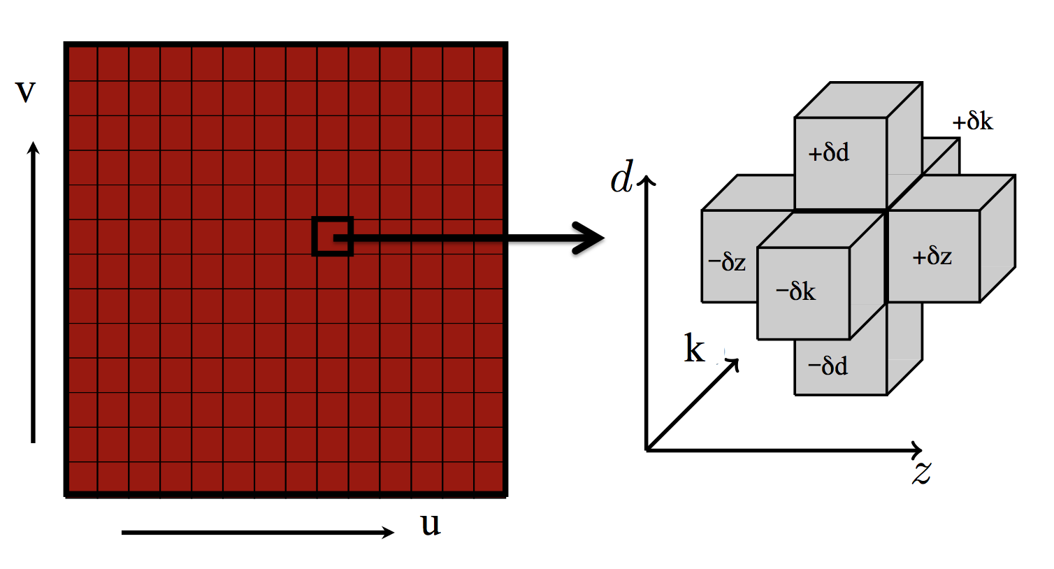
For each main cell , we calculate two subcells for each secondary parameter
, for a total of six “lateral cells”,
see figure 4.

Once a cluster over a threshold (a track) is found (), the track parameters are extracted finding the centre of mass of a -cells square:
| (3) |
with and . is the excitation intensity of the correspondent cell. The parameters are instead calculated by interpolating the response of the two lateral subcells corresponding to the considered parameter, for instance:
| (4) |
where assumes the values , and is the excitation intensity of the lateral cell corresponding to the cell. The same holds for and .
Because of the forward detector geometry and the topology of physics events, tracks are not uniformly distributed in the space of parameters, leading to an inefficient cells distribution, if uniformly sampled. We have performed appropriate non-linear transformation of coordinate measured on the virtual plane, to achieve a track distribution which is uniform in the space. It may be noted that this transformation has a close similarity with what the real retina achieves with the non-uniform distribution of photoreceptors in the fovea. The non-linear transformation is derived using the probability distribution of tracks in the parameter space evaluated from a minimum-bias data sample from the official LHCb-Upgrade simulation.
4 Retina performances
The algorithm described in this paper is implemented in a software package called Retina Simulator. The simulator is completely written in C++ [11] and it uses the ROOT data analysis framework [12]. As well as to evaluate the performances of the algorithm, in a real experiment, the retina simulator has been also developed to drive and assist the hardware implementation of the retina algorithm on FPGAs (more details in [9]). All the features discussed in the previous section are implemented in the simulator. In addition, it interfaces the official LHCb simulation, being able to process simulated LHCb events. The receptors banks are extracted from the LHCb simulation. For each cell of the parameter space a particle (a muon), with parameters corresponding to the central values of the cell, is “shot” through the detector. Intersections of this sample track with the detector layers are the receptors of the cell.
The main -subspace is divided into cells, a granularity larger than the maximum expected number of tracks in a typical LHCb-Upgrade event. The steps chosen for the lateral cells are , and .


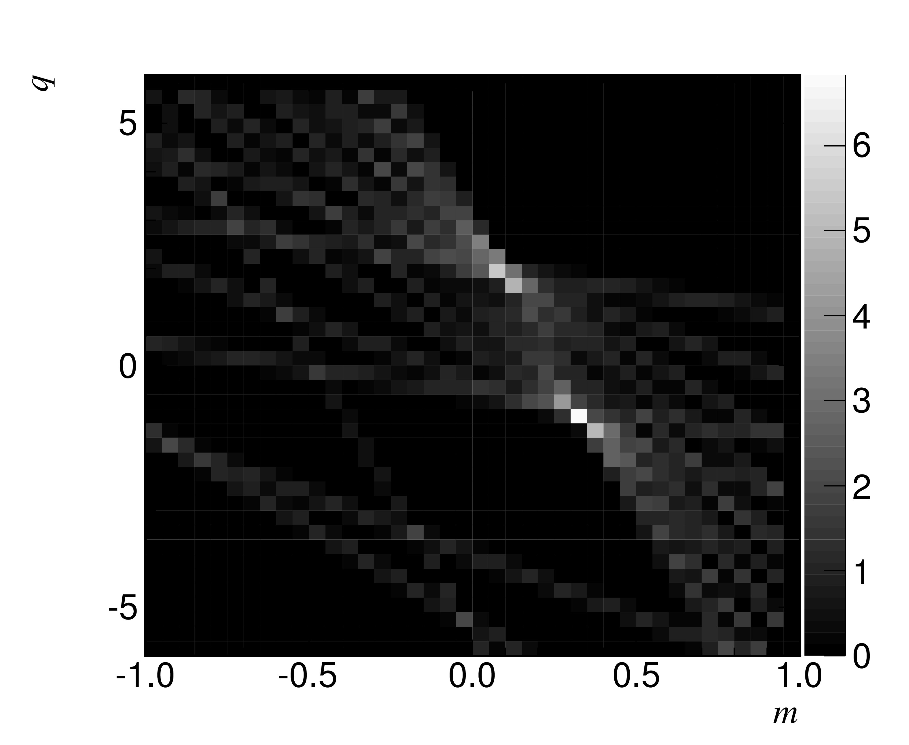
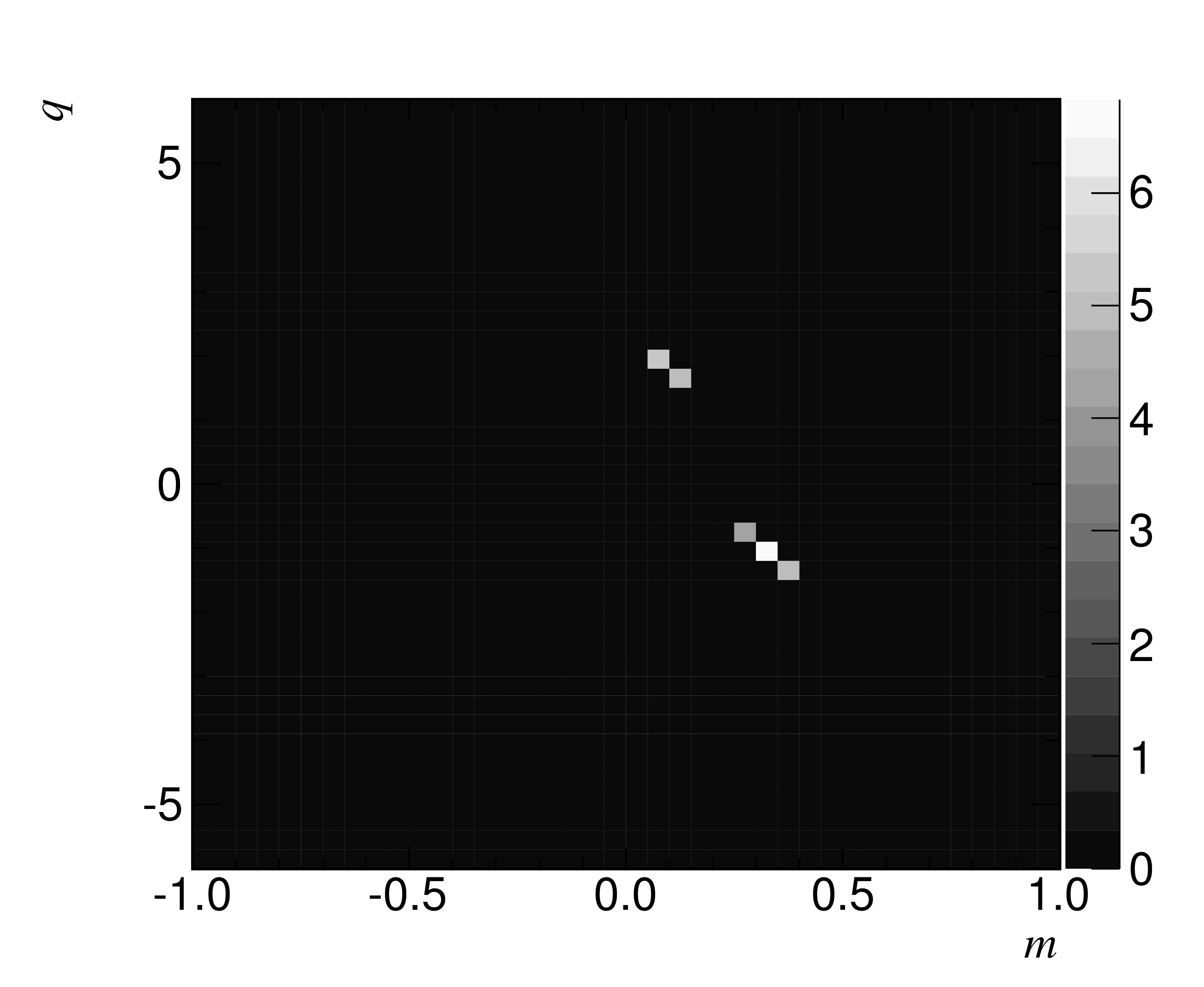
Generic collision samples from the LHCb simulation are used to assess the performances of the retina algorithm. Events are generated with PYTHIA 8 [13], with beam energy of , in the two luminosity scenarios expected for the LHCb-Upgrade operation: (i) , with an average number of interactions per bunch crossing equal to ; (ii) , where the average number of interactions per bunch crossing is equal to . A typical response of the retina algorithm to a simulated event of the LHCb experiment is shown in figure 5, where several clusters are clearly identifiable, and most of them reconstructed as tracks.
To benchmark the retina performances we compare the retina algorithm with the the first stage of the LHCb-Upgrade tracking sequence, named VELOUT algorithm [6]. Since the chosen layer configuration has a different acceptance with respect to the the VELOUT algorithm, we considered only tracks in the region of the -plane corresponding approximatively to . In addition, we required at least three hits on VELO layers and two hits on UT layers. Further cuts on momentum and on transverse momentum of the track are also applied. Tracks satisfying these requirements are defined as reconstructable, and the tracking efficiency is defined as the number of reconstructed tracks over the number of reconstructable tracks. The efficiency of the retina is reported in figure 6 as function of parameters. By comparison we also report the efficiency of VELOUT algorithm, performing the same task as the retina [6, 10].
The retina algorithm shows very high efficiencies in reconstructing tracks, 95% for minimum-bias tracks, which is comparable to the offline tracking algorithm. The fake track rate is 8% at and 12% at , at the same level of that obtained by the offline algorithm [6]. We also estimate the efficiency of the retina algorithm in reconstructing signal tracks from some benchmark decay modes, such as , and for , which are reported in table 1. Similar results have been found at .
| (signal tracks) | 0.97 |
|---|---|
| (signal tracks) | 0.97 |
| (signal tracks) | 0.98 |
We also investigated track parameter resolution returned by the retina algorithm. We found a resolution comparable to the offline algorithm, taking into account the differences between our layers configuration and that one used by the official offline algorithm, which uses all VELO layers and both axial and stereo UT layers. For instance the measurement of the track curvature performed using the retina algorithm is less precise by a factor (see figure 7), which is in agreement with the expected degradation due to the lack of the stereo layers information in the retina algorithm [10].

Among all track parameters, we focused our studies on the curvature resolution, since it is the most important track parameter providing discriminating power between heavy flavor signal events and background events. Experience from past experiments, as CDF, and LHCb itself demonstrated that requirements on lifetime related quantities, as the impact parameter, are effective only if a requirement on track momentum has been previously applied. Preliminary studies have shown that no degradation in resolution is expected for the measurement of track parameters if the same number of detector layers is used for both algorithm.
5 Conclusions
We presented the first implementation of the artificial retina algorithm into a real HEP environment like LHCb-Upgrade experiment. Performances of the algorithm were investigated. Excellent performances have been found for the retina pattern-recognition. Furthermore, it comes out that the retina has a high efficiency on heavy quarks decays channels. The retina algorithm is a powerful algorithm that exploits massive parallelism and in conjunction with high-end FPGAs can provide a high-quality track reconstruction at the full LHC crossing rate [9, 10].
References
- [1] L. Ristori, An artificial retina for fast track finding. NIM 453 (2000) 425-429.
- [2] D. H. Hubel and T. N. Wiesel, Receptive fields, binocular interaction and functional architecture in the cat’s visual cortex. The Journal of physiology, 160(1):106 (1962).
- [3] N. J. Priebe and D. Ferster, Mechanisms of neuronal computation in mammalian visual cortex. Neuron, 75(2):194–208, (2012).
- [4] LHCb Collaboration, Framework TDR for the LHCb Upgrade. LHCb-TDR-12 (2012).
- [5] LHCb Collaboration, The LHCb detector at LHC. JINST 3:S08005 (2008).
- [6] E. Bowen and B. Storaci, VeloUT tracking for the LHCb Upgrade. LHCb-PUB-2013-023 (2014)
- [7] LHCb Collaboration, LHCb VELO Upgrade Technical Design Report. LHCB-TDR-013 (2013).
- [8] LHCb Collaboration, LHCb Tracker Upgrade Technical Design Report. LHCB-TDR-015 (2014).
- [9] D. Tonelli et al., The artificial retina processor for tracking at 40 MHz. These proceedings (2014) [\hrefhttp://arxiv.org/abs/1409.1565arXiV:1409.1565].
- [10] A. Abba et al., A specialized track processor for the LHCb upgrade. CERN-LHCb-PUB-2014-026 (2014).
- [11] B. Stroustrup, The C++ Programming Language. Addison-Wesley Longman (2000).
- [12] R. Brun, F. Rademakers, Root – an object oriented data analysis framework. AIHENP’96 Workshop, Lausane vol. 389 (1996).
- [13] T. Sjostrand et al., A Brief Introduction to PYTHIA 8.1. Comput.Phys.Commun. vol. 178 (2008).