Femtosecond Time-Bin Entangled Qubits for Quantum Communication
Abstract
We create pairs of non-degenerate time-bin entangled photons at telecom wavelengths with ultra-short pump pulses. Entanglement is shown by performing Bell kind tests of the Franson type with visibilities of up to 91 %. As time-bin entanglement can easily be protected from decoherence as encountered in optical fibers, this experiment opens the road for complex quantum communication protocols over long distances. We also investigate the creation of more than one photon pair in a laser pulse and present a simple tool to quantify the probability of such events to happen.
I Introduction
Entanglement is one of the most important tools for the realization of complex quantum communication protocols, like quantum teleportation or entanglement swapping, and due to their ability to be transported in optical fibers, photons are the best candidates for long distance applications weihs . Even though some of these protocols have already been experimentally realized dik ; Boschi ; fur ; kim ; martini ; Pan ; thomas , none of them was optimized for long distance communication. Most of them used polarization entangled photon pairs in the visible range which are subject to important attenuation, and suffer from decoherence (depolarization) due to polarization mode dispersion (birefringence) in optical fibers. Energy-time entanglement or its discrete version, time-bin entanglement jurgen , is more robust for long distance applications. Both types have been proven to be well suited for transmission over more than 10 km 10km ; rob , and have already been used for quantum cryptography crypto1 ; crypto2 . However these experiments did not rely on joint measurements of photons from different pairs where the emission time of each pair must be defined to much higher precision. For this purpose we built and tested a new source using femtosecond pump pulses. This is the first femtosecond source at telecommunication wavelengths, and the first femtosecond source employing time-bin entanglement. This will allow realization of teleportation and entanglement swapping over long distances.
Apart from ensuring good localization of the photon pairs a femtosecond pulse engenders a significant probability of creating a pair per pulse due to the high energy contained in each pulse, an important requirement when two pairs have to be created at the same time. However when this probability becomes significant, the probability of creating unwanted multiple pairs becomes higher. Thus, the purity of entanglement will decrease, a phenomenon which is unwanted for almost all quantum communication protocols (Bell test, cryptography, teleportation etc.). For instance, the photon pair visibility in a Bell type test will strongly depend on the relation between the multiple pairs. They can be either independent or they can be described as multiphoton entanglement.
In the following we first remind the reader of the basic principle of time-bin entanglement, and we explain how to test entanglement. We then describe the experimental setup we used and present the results. In addition, we experimentally verify the reduction of the visibility due to multiple pair creation. Finally, we present a straightforward measurement of the probability to create a pair per pulse.
II Femtosecond time-bin entanglement
A time-bin qubit is formed by a coherent superposition of amplitudes describing a photon to be in two time-bins separated by a time difference which is much larger than the coherence time of the photon. It is created by a short pulse, in our case a femtosecond pulse, passing through an unbalanced interferometer, referred to as the pump interferometer, with a relative phase between the two arms. The output state of the photon, after the pump interferometer, can be written as:
| (1) |
The state corresponds to the case where photons are in the first time-bin (passing zero times through the long arm of any interferometer), photons are in the second time-bin (passing once through a long arm of any interferometer), photons are in the third time-bin (passing through the long arms of two different interferometers) etc. Entangled time-bin qubits are created by passing a time-bin qubit through a non linear crystal where eventually twin photons can be created by spontaneous parametric down conversion. The creation time is then given by superposition of two values:
| (2) |
Depending of the relative phase two out of four Bell states can be created (). The two remaining Bell states () can be created in principle with switches and delays after the crystal.
II.1 Bell test
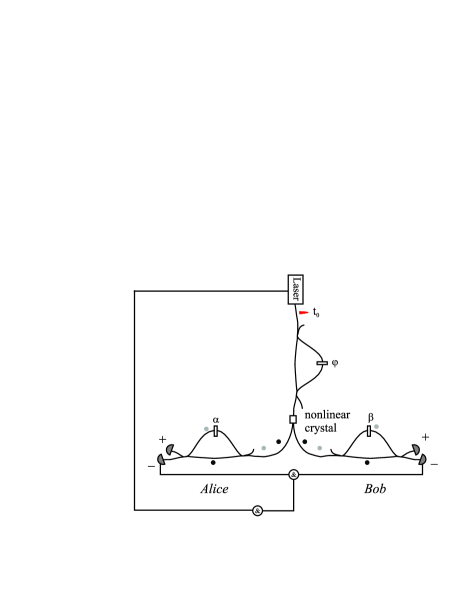
To qualify the purity and degree of entanglement we perform a Bell test (Franson type) Franson . One of the photons is sent to Alice and the other one to Bob (see figure 1).
To analyze the received qubit, Alice and Bob undo the initial transformation with an interferometer which has the same optical path length difference as the pump interferometer. The initial state evolves as follows:
| (3) |
With this evolution Eq.2 becomes:
| (4) |
In the following discussion we are interested only in coincidences between and detectors (see figure 1). If we monitor the difference of arrival times of two entangled photons at Alice’s and Bob’s side (), with a time to amplitude converter (TAC) we distinguish three different peaks (see figure 2).
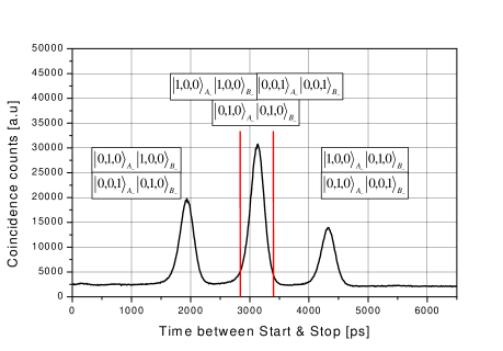
The two satellite peaks correspond to events that are well distinguishable or for the left satellite peak and or for the right satellite peak. These peaks can be discarded by selecting a sufficiently small time window around the central peak. In the central peak three events (due to Alice’s and Bob’s photons taking the same path in the respective interferometers) are counted: , and . The first (second) event corresponds to the case when the photons created in the first (second) time-bin pass through the short (long) arm of Alice’s and Bob’s interferometer. The third event corresponds either to the case when the photons created in the first time-bin pass through the long arm of Alice’s (acquiring a relative phase ) and Bob’s (acquiring a relative phase ) interferometer or to the case when the photons created in the second time-bin (with a relative phase ) pass through the short arm of Alice’s and Bob’s interferometer. The impossibility to distinguish, even in principle, via which path the photons have passed leads to interference. Knowing the emission time of the pump pulse we can distinguish two out of three events ( and ) thus the visibility as observed in the two photon interference while changing the phase in one of the three interferometers is limited to 50 %. To increase the visibility to 100 % we postselect the third event by making a three fold coincidence between the emission time of the pump photon, and Alice’s and Bob’s detection (see figure 1). Thus the post selected state is:
| (5) |
with the amplitude of probability to be detected
Where , and are the relative phases of the pump, Alice’s and Bob’s interferometer, respectively. The triple coincidence counting rate is, thus, given by:
| (6) |
where V is the visibility which can in principle reach the value of 1. We take it as the figure of merit to quantify the entanglement. Note that correlation described by such coincidence functions with a visibility higher than 70.7 % can not be described by local theories CHSH .
II.2 Experimental setup
A mode locked Ti:Sapphire laser (Coherent Mira 900) produces pulses at =710 nm with 150 fs pulse width and 76 MHz repetition rate. To remove all unwanted infrared light the light passes through a series of dichroic mirrors, reflecting only wavelengths centered around 710 nm. The superposition of discrete times is made by a bulk Michelson interferometer with a path-length difference of 1.2 ns foot2 . The entangled non-degenerate colinear photons at 1310 and 1550 nm (telecom wavelengths) are created in a KNbO3 type I nonlinear crystal. The pump light is removed with a RG 1000 filter, the twin photons are collimated into an optical fiber and separated by a wavelength-division-multiplexer (WDM). The analyzers are two Michelson fiber interferometers with Faraday rotator mirrors. The role of these mirrors is to compensate any difference of polarization transformation in the two arms of the interferometer plug ; pluga . The phase is tuned by varying the temperature of the interferometer.
At Alice’s side the photon counter at 1310 nm is a passively quenched Germanium APD, cooled with liquid nitrogen and working in reversed mode above the breakdown voltage (so called Geiger mode). The quantum efficiency is around 10 % for a dark count rate of 20 kHz. At Bob’s side the photons at 1550 nm are detected by a InGaAs APD, Peltier cooled to around -50 ∘C. To obtain a good signal to noise ratio, these APDs have to be used in so called gated mode. They are then operational only during a short period (around 50 ns) when a photon is expected to arrive. Thus, the InGaAs APD is triggered by the Ge APD. Its quantum efficiency is around 30 % for a darkcount probability of 10-4 per ns JDG .
The twin photons, due to our phasematching conditions, have a large spectral bandwidth of around 90 nm. To reduce the effect of chromatic dispersion in our interferometers we limit the spectral width of the downconverted photons with an interference filter at Alice’s side ( nm) foot21 and we use dispersion shifted fibers for Bob’s interferometer. In addition, spectral filtering of the 1310 nm photons leads to a decrease of the count rate of the Ge-detector, hence to a decrease of the trigger rate for the InGaAs APD which enables to operate them at a higher quantum efficiency.
II.3 Results of the measurement
Figure 3 shows the results of a typical interference curve.
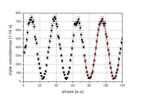
The visibility of the interference fringes, after subtraction of the noise, is 91 0.8 % (computed using a sinusoidal fit). This result shows that the created state is not far from a pure maximally entangled state, sufficiently entangled to be used in quantum communication protocols. Please note that only the net visibility is important in this context. Indeed we have to subtract the accidental coincidences from the raw visibility since they are due to a combination of fiber losses, non-perfect quantum efficiency and detector noise, and not to reduced entanglement. However, if we assume (in addition to foot3 ) that the accidental coincidences are measured in a fair way, our net visibility is high enough to violate the CHSH inequality CHSH by more than 25 standard deviations.
Note that with this source, creating entangled photons with the same polarization and using time-bin entanglement, we did not have problems met by other groups creating polarization entangled photons with a femtosecond pulsed laser shih . The quality of our entanglement is not degraded by the use of the long crystal ( mm) and large interference filters ( nm).
III Multiphoton states
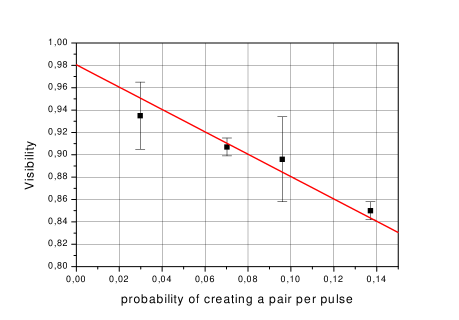
The above mentioned results were obtained using a mean pump power of 24 mW. By increasing the pump power the probability of creating more than one pair per pulse increases too, thus the visibility of the two-photon interference fringes decreases. Although the pump power was chosen in order to get good visibilities this effect is still present. Figure 4 shows the decrease of the visibility as a function of the pump power.
The decrease of the visibility can be understood with the following simple calculation, that can be rederived using the full formalism of quantum optics sca . The detection rate is the sum of two mutually incoherent contributions: , the detection rate associated to the production of one pair; and , associated to the production of four photons. The two-photon contribution has 100% visibility, thence we can write
| (7) |
where is the probability of creating one pair and . We discuss the four-photon contribution supposing that the four-photon state is actually two independent pairs, which is not strictly speaking true, but is a good guide for the intuition — moreover, the final result turns out to be independent of this assumption sca . Thus we have two possible cases: when the two photons that are detected belong to the same pair, shows full interference; when they belong to different pairs, shows no interference at all. Each of the situations happens twice, because the two pairs may have been created either both in the same pulse, or one in each pulse. Thus
| (8) | |||||
Now assuming a Poissonian distribution for counting of independent events, the probability of creating four photons is . So finally
| (9) |
whence the total visibility is , predicting a slope of .
IV Characterization of the source
As we have seen in the last section it is important to get a fast and reliable estimation of the probability of creating a pair per pulse. Usually this probability is computed from:
| (10) |
where is the probability of creating a pair per pulse, is the number of photons detected by Alice, characterizes coupling and transmission, is the quantum efficiency of Alice’s detector and is the laser frequency. In this case we have to estimate the values of and (the quantum efficiency can be measured but it is not a straightforward measurement).
We present in this section a new, easily visualized and straightforward way
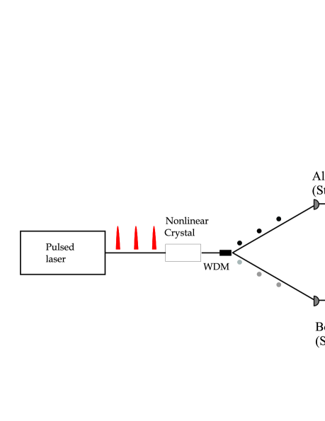
of measuring this probability. The experimental setup is very simple:
A series of femtosecond pulses pass through a non linear crystal creating
pairs of photons at 1310 and 1550 nm which are separated with a WDM (see figure 5). Each of
them is detected with the same detectors as in the previous experiment and
the difference of arrival times between Alice’s and Bob’s photon is measured
with a TAC.
If every created photon was detected, we would obtain only one main peak, but because of imperfect detector efficiency, coupling and transmission losses we observe the apparition of, what we call, side peaks (see figure 6). These side peaks have been observed in different context as well (for instance baby ).
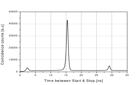
The right (left) side peak is due to events where the start at Alice’s side is given by a photon created by a pulse, but where its twin is not detected at Bob’s side. The stop is then given by another photon created by the following (preceding) pulse. By measuring the ratio between the main peak and the side peak we obtain directly the wanted probability :
| (11) |
This equation holds only for . The theoretical development is presented in the appendix.
Figure 7 depicts the pair creation rate, calculated from the ratio of side to main peak (Eq.11), as a function of the single count rate of the Ge-detector. The solid line shows the prediction based on Eq.(10) where we estimate and erreur . We see that both methods are in qualitative agreement, however the deviation of the measured points from the solid line is due to the fact that in practice vary.
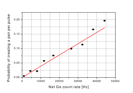
Our new method has two main advantages compared to the standard one (Eq.(10)): It is easily visualized and it immediately gives a good indication as to whether the probability to have more than one pair is significant; Secondly, no estimation has to be done, the probability is computed only from measured values and the uncertainty of, is smaller than when using the method mentioned previously (see appendix).
V Conclusion
In this paper we presented a new source for realization of complex quantum protocols over long distances. This new source is the first one creating time-bin entangled qubits at telecom wavelengths with ultrashort pulses. We characterized this source by performing Bell type tests, obtaining net coincidence visibilities of up to 91 0.8 %. We found that the change of visibility with pump power depends on the process of creation of the entangled time-bin qubits (femtosecond or picosecond pump pulses). Finally, we presented a new and simple tool for measuring the probability of creating a pair per pulse.
This work was supported by the Swiss OFES in the frame of the European QuComm IST project and by the Swiss NCCR ”Quantum Photonics”. W.T. acknowledges funding by ESF Programme Quantum Information Theory and Quantum Computation (QIT).
VI Appendix
Figure 6 shows the histogram of the photons arrival time difference at Alice’s and Bob’s detector. When there is a detection in the main peak then start and stop are given by photons created by the same pump pulse. If N is the number of pairs created per pulse then the probability of detecting a coincidence is given by:
Here, is the probability of having N pairs knowing that there was a start. is the probability of detecting a stop by one of the photons created by the same pulse as the one that gave the start.
The first term can be easily computed with Bayes’ rule:
where is the probability that pairs are emitted. If pairs are created, the probability that the start is not given is , where describes the probability that a created photon passes through a possibly included interference filter — that is, if there is no filter; as in the main text, characterizes the coupling ratio and transmission, and is the quantum efficiency of the detector. Therefore, the probability of having a start knowing that pairs were created is given by
Of course, , but this is a global factor that plays no role in what follows.
In the same way we find
where is the probability that a photon at Bob’s side passes through an interference filter knowing that its twin photon has already passed through an interference filter at Alice’s side, thus when foot21 . We assume that the spectrum of the created photons is centered at the maximum transmission of the interference filters.
The probability of detecting a coincidence in the right side peak is given by:
| (12) |
The first term represents, as before, the probability of having N pairs knowing that there was a start, the second is the probability not to detect a stop originating from the same pump pulse; is the probability that the stop is given by a photon created by the first pulse following the one which gave the start. Explicitly
note that here we have instead of
, since we don’t
require that the twin photon has passed through the corresponding
filter.
We now suppose that the mean number of pairs is much smaller than 1, so that and . From the equations above, we find the ratio between main and side peak to be:
| (13) |
If there is only a filter at Alice’s side (as was in our Bell type
experiment) and , we find equation (11)
( and ). Thus, if one wants to measure the probability
of creating a pair per pulse in a given spectral bandwidth, one
has to filter both photons.
Finally, using this method, the uncertainty of is
reduced compared to the standard method (Eq.10). For
instance, if we estimate and , then the relative uncertainty of , calculated
using Eq.10, is 30 % while it is only of 3 %
using
our new method (Eq.11).
References
- (1) W. Tittel and G. Weihs, Quantum Information & Computation, Volume 1, Number 2, 5 (2001)
- (2) D. Bouwmeester, J.W. Pan, K. Mattle, M. Eibl, H. Weinfurter, and A. Zeilinger, Nature 390, 575 (1997)
- (3) D. Boschi, S. Branca, F. De Martini, L. Hardy, and S. Popescu, Phys. Rev. Lett. 80, 1121 (1998)
- (4) A. Furusawa, J. L. S rensen, S. L. Braunstein, C. A. Fuchs, H. J. Kimble, and E. S. Polzik, Science 282, 706 (1998)
- (5) Y.-H. Kim, S.P. Kulik, and Y. Shih, Phys. Rev. Lett. 86, 1370 (2001)
- (6) E. Lombardi, F. Sciarrino, S. Popescu, and F. De Martini, Phys. Rev. Lett. 88, 070402 (2002)
- (7) J.-W. Pan, D. Bouwmeester, H. Weinfurter, and A. Zeilinger, Phys. Rev. Lett. 80, 3891 (1998)
- (8) T.Jennewein, G. Weihs, J.W. Pan, and A. Zeilinger , Phys. Rev. Lett. 88, 017903 (2002)
- (9) J. Brendel, N. Gisin, W. Tittel, and H. Zbinden, Phys. Rev. Lett. 82, 2594 (1999)
- (10) W. Tittel, J. Brendel, H. Zbinden, and N. Gisin, Phys. Rev. Lett. 81, 3563 (1998)
- (11) R.T. Thew, S. Tanzilli, W. Tittel, H. Zbinden, and N. Gisin, quant-ph/0203067 (2002)
- (12) W. Tittel, J. Brendel, H. Zbinden, and N. Gisin, Phys. Rev. Lett. 84, 4737 (2000)
- (13) G. Ribordy, J. Brendel, J-D. Gautier, N. Gisin, and H. Zbinden, Phys. Rev. A 63, 012309 (2001)
- (14) J.D. Franson, Phys. Rev. Lett. 62, 2205 (1989)
- (15) J. F. Clauser, M.A. Horne, A. Shimony, and R.A. Holt, Phys. Rev. Lett. 23, 880 (1969)
- (16) The main reason why we use a bulk interferometer is to avoid high chromatic dispersion at 710 nm in optical fibers
- (17) G. Ribordy, J-D. Gautier, N. Gisin, O. Guinnard, and H. Zbinden, Electronics Letters 34 (22), 2116 (1998)
- (18) H. Zbinden, J-D. Gautier, N. Gisin, B. Huttner, A. Muller, and W. Tittel, Electron. Lett. 33 (7), 586 (1997)
- (19) D.Stucki, G. Ribordy, A. Stefanov, and H. Zbinden, J. of Mod. Optics, 48 (13), 1967 (2001)
- (20) Note that the spectral filtering of one entangled photon also filters its twin photon
- (21) To affirm that we violate Bell inequalities, we have to make the (reasonable) assumption that the other (not recorded) triple coincidence have the same behavior and that all coincidence count rates depend only on the sum of the phases
- (22) Y.H. Kim, M.V. Chekhova, S.P. Kulik, M.H. Rubin, and Y. Shih, Phys. Rev. A 63, 062301 (2001)
- (23) V. Scarani, A. Acin, N. Gisin, H. de Riedmatten, I. Marcikic, and H. Zbinden, in preparation
- (24) C. Santori, D. Fattal, M. Pelton, G.S. Solomon, and Y. Yamamoto, cond-mat/0111242 (2001)
- (25) The estimation of Alice’s coupling ratio and transmission () is made by assuming that it is comparable to Bob’s () which can be measured knowing the coincidence count rate, the count rate of the Ge-detector and the quantum efficiency of InGaAs APD.