A Tight Bound for Probability of Error for Quantum Counting Based Multiuser Detection
Abstract.
Future wired and wireless communication systems will employ pure or combined Code Division Multiple Access (CDMA) technique, such as in the European 3G mobile UMTS or Power Line Telecommunication system, but also several 4G proposal includes e.g. multi carrier (MC) CDMA. Former examinations carried out the drawbacks of single user detectors (SUD), which are widely employed in narrowband IS-95 CDMA systems, and forced to develop suitable multiuser detection schemes to increase the efficiency against interference. However, at this moment there are only suboptimal solutions available because of the rather high complexity of optimal detectors. One of the possible receiver technologies can be the quantum assisted computing devices which allows high level parallelism in computation. The first commercial devices are estimated for the next years, which meets the advert of 3G and 4G systems. In this paper we analyze the error probability and give tight bounds in a static and dynamically changing environment for a novel quantum computation based Quantum Multiuser detection (QMUD) algorithm, employing quantum counting algorithm, which provides optimal solution.
Key words and phrases:
Multiuser detection, Quantum Counting, Grover’s Algorithm, Quantum computing, Quantum Signal Processing1. Introduction
The subscribers of next generation wireless systems will communicate simultaneously, sharing the same frequency band. All around the world 3G mobile systems apply Direct Sequence - Code Division Multiple Access (DS-CDMA) promising high capacity and inherent resistance to interference, hence it comes into the limelight in many communication systems. Nevertheless due to the frequency selective property of the channel, in case of CDMA communication the orthogonality between user codes at the receiver is lost, which leads to performance degradation. Single-User detectors were overtaxed and shown rather poor performance even in multi-path environment [verdu]. To overcome this problem, recent years multiuser Detection (MUD) has received considerable attention and become one of the most important signal processing task in wireless communication.
Verdu [verdu] has proven that the optimal solution is consistent with the optimization of a quadratic function, which yields in MLSE (Maximum-Likelihood Sequence Estimation) receiver. However, to find the optimum is an NP-hard problem as the number of users grows. Many authors proposed sub-optimal linear and nonlinear solutions such as Decorrelating Detector, MMSE (Minimum Mean Square Error) detector, Multistage Detector, Hoppfield neural network or Stochastic Hoppfield neural network [verdu, dejou00, var90], and the references therein. One can find a comparison of the performance of the above mentioned algorithms in [dejou01].
Nonlinear sub-optimal solutions provide quite good performance, however, only asymptotically. Quantum computation based algorithms seem to be able to fill this long-felt gap. Beside the classical description, which we recently use, researchers in the early century raised the idea of quantum theory, which nowadays becomes remarkable in coding theory, information theory and for signal processing [pres98].
Nowadays, every scientist applies classical computation, using sequential computers. Taking into account that Moore’s law can not be held for the next ten years because silicon chip transistors reach atomic scale, therefore new technology is required. Intel, IBM, AT&T and other companies invest large amount of research to develop devices based on quantum principle. Successful experiments share up that within 3-4 years quantum computation (QC) assisted devices will be available on the market as enabling technology for 3G and 4G systems [imr01b, imr01c].
This paper is organized as follows: in Section 2 we shortly review the necessity of multiuser detection, as well as the applied quantum computation method is shown. In Section 3 the proposed quantum multiuser detector model is introduced. Furthermore, in Section 4. we give and proof a tighter probability error for our model. Finally we conclude our paper in Section LABEL:sec:conc.
2. Theoretical Backgrounds
2.1. Multiuser Detection
One of the major attributes of CDMA systems is the multiple usage of common frequency band and the same time slot. Despite the interference caused by the multiple access property, the users can be distinguished by their codes. Let us investigate an uplink DS-DCDMA system, where the symbol of the user is denoted by , . In DS-CDMA systems an information bearing bit is encoded by means of a user specific code with length of the processing gain (PG)[verdu]. In case of uplink communication we assume perfect power control. In the receiver side it is not required synchronization between input signals and user specific codes, however we make our decision on symbols. Applying BPSK modulation, the output signal of the user, denoted by , is given as
where and are the energy associated to the and the user continuous signature waveform, respectively
denotes the time duration of one chip, is the chip of the code word of subscriber and refers to the chip elementary waveform. We investigate a one path uplink wideband CDMA propagation channel. The channel distortion for the user is modelled by a simple impulse response function , where and are the path gain and the delay of the user, respectively [liu]. They are assumed to be constant during a symbol period of . This model contains almost all elements of a typical WCDMA channel except multipath propagation, which was omitted to simplify the explanation of the new quantum computation based multiuser detection scheme. However, based on the results of the present paper, multipath propagation can be included into the channel model on a very simple way.
The received signal is the sum of arriving signals plus a Gaussian noise component and thus can be written as follows:
where is the number of users using the same band, is a white Gaussian noise with constant spectral density.
Unfortunately, the search for the globally optimal MUD [verdu] usually proves to be rather tiresome, which prevents real time detection (its complexity by exhaustive search is ). Therefore, our objective is to develop new, powerful detection technique, which paves the way toward real time MUD even in highly loaded system. Since classical multiuser detection schemes only try to minimize the probability of error in noisy and high interference environment, they, even also optimal solutions, can commit an error. Actually, these classical approaches make compromize between computational complexity, probability of error and time barrier required for efficient working. On the other hand, QMUD provides for typical CDMA systems and it is able to indicate undistinguishable decision situations for correction by higher layer protocols [imr01].
2.2. Quantum Computation Theory
Quantum theory is a mathematical model of a physical system. To describe such a model one needs to specify the representation of the system. According to the axioms of quantum mechanics, every physical system can be characterized by means of its states 111Say ket (using Dirac’s notation). in the Hilbert vector space over the complex numbers , whereas a physical quantity can be described as Hermitian operator , respectively.
In the classical information theory the smallest information conveying unit is the bit. The counterpart unit in quantum information is called the ”quantum bit”, the qubit. Its state can be described by means of the state , , where refers to the complex probability amplitudes, where [shor98, pres98]. The expression denotes the probability that after measuring the qubit it can be found in computational base , and shows the probability to be in computational base . In more general description an -bit ”quantum register” (qregister) is set up from qubits spanned by computational bases, where states can be stored in the qregisters at the same time [imr01], describing
| (2.1) |
where denotes the number of states and , , , , respectively. It is worth mentioning, that a transformation on a qregister is executed parallel on all stored states, which is called quantum parallelization.
3. Quantum multiuser Detector Employing Quantum Search
For the optimal decision it would be necessary a fully comprehensive knowledge about the symbols sent by all the subscribers in the coverage area of base station, a realization of the delay and noise, which is typical for a particular communication channel and all the user specific codes. All this information cannot be stored in a single database, which should be build just one time at all. In pursuance of detection one compares the quantized received signal with the content of the database. This task can be done efficiently, employing the Grover [gro96, gro00] database search algorithm , which is proved to be optimal [zal99] in steps, where denotes the length of the database.
The optimal number of iterations is depending on the initial angle between the initial state and , as well as the number of the identical entries in the database. In [gro96] it was shown that the rotation of state to the desired state after evaluations of Grover operator is
| (3.1) |
whereas in [zal99] it was proved that the optimal number of iterations is given as
| (3.2) |
In case of or even it exists no multiple entries in the qregister the angle
| (3.3) |
where the optimal number of evaluations is equal to [zal99]. It is worth mentioning that in case of , the initial angle , which leads to only one evaluation.
In case of quantum detection, however, it is not required to know the exact position of the representative of the received signal in the qregister, only whether is it contained in the database or not. For this purpose, the so called Quantum Counting based on Quantum Fourier Transformation (QFT) designed for phase estimation is well suited. In the following part of this section we introduce the buildup of the applied databases, qregisters. Furthermore, we shortly discuss the quantum counting problem and our way to deal with quantum multiuser detection problem.
3.1. Applied Databases and Qregisters
Let us assume we would like to detect the user’s symbol, denoted by . To design a suitable multiuser detector all of the user specific code words have to be known at the base station, collected in a sized database . In addition we create a qregister , which contains all the possible received signal configurations without
| (3.4) |
where are the computational base states. Since every possible noise and delay states for a given transmitted bit is involved in the prepared register, it is superfluous to send any phase information, which allows non-coherent detection. The first qubits represent all the combination of the symbols transmitted by all the interferer, e.g. if the value of qubit in a given is equal to 1, it shows that the user has been transmitted a symbol denoted by , otherwise if the qregister has an entry . For a proper utilization of the qregister the next two parts in is reserved for all quantized state of the noise and the delay : . For the sake of simplicity we assume to apply a linear quantization , where and refers to the quantization step. It is remarkable, if the probability density function (pdf) of the target quantity is known, such as by the Gaussian noise, an adequate nonlinear quantization could be used, whereby most significant values can be sampled denser, which can decrease the number of required qbits for description of noise. The values of the delay can be generated in a straitforward manner, , where could be . With the above mentioned description the size of qregister is given by
| (3.5) |
where denotes the round up operation to the next integer. We consider two independent qregisters and for every user according to sent information symbol or . From this point we just refer to , where , however, the operations on each qregister can be done in the same manner. Thus, are the databases as well as detection means to check whether the received signal can be found in the databases [imr01c].
3.2. Quantum Counting
Performing multiuser detection it is obvious not to look for a pattern in a database itself but to indicate whether or not a solution even exists, consequently, the number of solutions have to be summed up. This quantum counting algorithm can be accomplished with combining the Grover quantum search algorithm mentioned in Section 3, with the phase estimation based on the quantum Fourier transformation [nielsen]. The quantum counting algorithm is able to estimate the eigenvalues of a unitary operation , or in this case the Grover iterations
| (3.6) |
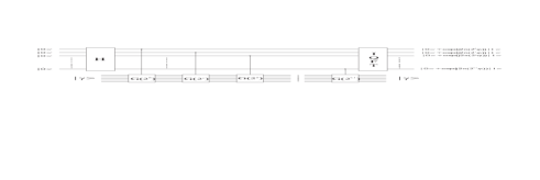
which is in a close connection with the demanded number of solutions on the search. In addition to the original Grover circuit a new register of new qubits should be feed to the quantum counting algorithm, whose state is initialized to an equal superposition of all possible inputs by a Hadamard gate, as in Figure 1. The vector , which contains all the possible signal states with equally distributed probability amplitudes, is build up in the same way. The original Grover block becomes a controlled Grover block, where the transformation (a rotation with angle , such as in the original Grover algorithm) will be only evaluated if the control signal equals to one. The goal of quantum counting is to estimate to bits of accuracy, with probability of success . The state of the register after the controlled Grover iterations is
| (3.7) |
which is exactly the QFT belonging to . Hence, to estimate an inverse quantum Fourier transformation is executed on (3.7) before the measurement. In case of after a measurement, the demanded pattern is contained in the qregister , and if it is equal to zero, it is not included in.
4. The required number of additional qubits
The required number of qubits
| (4.1) |
in , and hereby the required number of Grover blocks can be calculated in function of desired accuracy of and the probability of false detection. This error is occurred if is not in form of , where . Hence it can be regarded as the probability of false detection.
Lemma 4.1.
The accuracy of can be given as
| (4.2) |
Proof.
Fortunately, we are able the upperbound in (4.1). From the accuracy point of view the worst case is occurred if , because the initial angle , yielding form (3.3), is the smallest. Hence, should be chosen as large as possible, which leads to
∎
Therefore, we have a direct connection between the detection error probability and the required length of register . However, before the measurement an inverse discrete QFT is done, which adds additional states beside with a given probability, if is not an integer power of two, that could lead to false detection in the receiver. Hence, the expression [nielsen] in (4.2) is just a approximation. In general, is needed to represent more precisely, and thus to decrease the probability of false detection, but the accuracy of the estimated angle is in the future too. This means, that only influences the probability amplitudes, which leads to be enough measuring the first most significant bits!
4.1. Methods to improve the measurement
To improve the proper error probability of detection, there are some possibilities.
-
(1)
One should chose , where . Unfortunately, except the trivial case, where , which means the desired state is not in the qregister, it happens very rarely.
-
(2)
Our goal is to distinguish the case from . It is known from the previous point, that the detection of is certain. Consequently, if a false detection is occurred if and only if we decide for after the measurement. For a more precise estimation of the error probability , one should extend the size of the qregister instead of bits, with more bits. We will show that based on our results can be much smaller than at a given , where
| (4.3) |
where refers to the estimated phase. The second part of the right side in (4.3) is equal zero, because of the previous analysis. Assuming an unknown a-priori probability (4.3) becomes simpler
The state of the examined qregister before measurement is given as
| (4.4) |
where is a real number. Furthermore, the probability amplitude of the state is
which is a geometrical series [nielsen]
| (4.5) |
The demanded probability of error can be described as the sum of over all probability amplitudes given in (4.5)
| (4.6) |
form which the parameter is calculable at a given .
4.2. Upper bound of error probability
While can not be expressed explicitly from (4.6), hence, in case of adaptive receiver structure it would be very useful to give less complex way of determine . For this purpose an upper bound has to be given for (4.5). It is considerable that with increasing the size of the qregister with new bits, the sum in (4.6) may also greater, however, due to more accurate representation of the probability amplitude belonging to the false vectors diminishes better and better.
4.2.1. Numerator of (4.5)
For the numerator of (4.5) in [nielsen] was shown an unambiguous upper bound , which is simple the diagonal of unit circle . We show now, that under certain conditions a tighter bound can be given.