Finite-Element Simulations of Rotating Neutron Stars with Anisotropic Crusts and Continuous Gravitational Waves
Abstract
“Mountains”, or non-axisymmetrical deformations in the elastic crust of rotating neutron stars are efficient radiators of continuous gravitational waves. Recently, small anisotropies were observed in the solid innermost inner core of the Earth [1]. We implement three-dimensional finite-element simulations to study mountains sourced by modest anisotropies in the solid crust of rotating neutron stars. We find that anisotropic mountains may be detectable by current ground-based gravitational-wave detectors and might explain several observed phenomena, confirming the results of a previous work on less realistic neutron star models [2]. In particular, we find that a slightly anisotropic neutron star crust that changes its rotation rate modestly can support an ellipticity of a few 10-9, which is equivalent to the upper bounds on the ellipticity of some nearby and rapidlly spinning pulsars [3].
I Introduction
In recent years, the scientific community has been profoundly impacted by groundbreaking discoveries regarding gravitational waves (GWs). The first detection of GWs occurred on September 14, 2015, when the LIGO and VIRGO collaborations identified bursts of GWs resulting from the inspiral and merger of two black holes [4]. Approximately two years later, on August 17, 2017, these collaborations made another historic observation: they detected GWs from the inspiral and merger of two neutron stars (NSs) [5]. Additionally, several pulsar-timing-array (PTA) collaborations have announced varying levels of confidence with respect to evidence for the existence of nano-Hertz stochastic GWs [6, 7, 8, 9],.
However, there is another type of GWs that has continually eluded detection: continuous GWs (CGWs). CGWs are continuous trains of GWs with a quasi-monochromatic frequency that evolve slowly over time. The most promising sources of CGWs are individual spinning NSs with time-varying mass quadrupoles. The two primary time-varying mass quadrupoles that can generate CGWs in rotating NSs are r-mode instabilities [10, 11] and non-axisymmetric deformations sustained by magnetic and/or elastic forces [12, 13, 14]. r-mode instabilities can be suppressed by various mechanisms. For instance, at low temperatures, shear viscosity can suppress the r-mode instability before it grows to a detectable level, while at high temperatures, bulk viscosity can have the same effect [15, 16, 17]. In addition, mode coupling can also suppress the r-mode instability [18]. Sustained non-axisymmetric deformations in rotating NSs are commonly referred to as “mountains”. Mountains sustained by magnetic forces are likely to emit CGWs that fall below the frequency range where ground-based detectors are most sensitive [19]. This is because the strong magnetic fields that create these mountains may also exert a magnetic torque that rapidly spins down the NS. Conversely, mountains can form in the crust (the solid outermost kilometer of a typical NS) and be sustained mainly by elastic forces if the magnetic fields are weak. These mountains are typically known as “elastic mountains” and are the most promising sources of CGWs because there is no significant magnetic torque to rapidly spin down the star and shift the frequency of the emitted CGWs to less sensitive bands of ground-based GW detectors. This work is focused on elastic mountains.
The instrumentation of ground-based GW detectors and the data analysis techniques used in CGW observational campaigns are continuously improving [20, 21, 22, 23, 24]. Remarkably, researchers started to develop neural network architectures to perform observational campaigns of CGWs [25]. Additionally, more galactic pulsars are being discovered, and more electromagnetic information is being collected from potential CGW sources [26, 27]. These advances enhance our GW constraints on known CGW sources and increase the likelihood of the first CGW detection in the coming years. However, there has not yet been a CGW detection, although there has been significant progress in the upper limits on the strengths of CGW signals. [28, 29, 30, 31, 3].
Given the lack of CGW detections, elastic mountains remain poorly understood. Nonetheless, there has been significant progress in the theoretical understanding of elastic mountains over the years. The calculation of the breaking strain of the NS crust has enabled the determination of the maximum mountain that the crust can support [32, 33, 34, 35]. Additionally, research studies have investigated elastic mountains arising from non-axisymmetric formation channels, including electron capture reactions [36] and temperature variations [13].
Crystals are anisotropic and tend to be oriented by sedimentation, freezing, recrystallization, deformation, and flow. The NS crust may be anisotropic as accretion moves material to greater densities where it may melt or freeze. Furthermore, recent observations of seismic waves reverberating through the Earth’s center showed that the solid innermost inner core of the Earth is anisotropic [1], with material properties that depend on direction. Motivated by these observations, in an earlier publication [2] we considered a solid NS crust with anisotropic stresses. Our study used a simplified two-dimensional geometry and a constant mass density crust model. It suggested that the centrifugal stress can form detectable mountains when coupled with the anisotropic shear modulus of the crust. We found that the size of these mountains evolves with the difference between the square of the final and initial rotational frequencies and scales linearly with the degree of anisotropy within the crustal material.
In this research work, we use three-dimensional finite-element simulations of a more realistic NS to enhance our model mountains that grow as the star with an anisotropic crust spins up or down. We simulate how the anisotropic shear modulus deforms the star as the crust is centrifugally stressed by a change in rotation rate. We also discuss the gravitational radiation emitted by this kind of deformations.
We emphasize that the basic assumption in this project is that the elastic stress of the crust is very slightly anisotropic, even when averaged over the whole crust. Specifically, we assume that the elastic stress tensor is given by,
| (1) |
where the first term is the contribution from the isotropic angle-averaged shear modulus, while the second term is the contribution from a small anisotropic perturbation to the isotropic angle-averaged shear modulus. The elastic stress tensor defined in equation (1) is explained with detail in section IV.3.
This paper is organized as follows. In section II, we introduce the concept of NS mountains. In section III, we present the background NS against which we perform a perturbative analysis to study the anisotropic NS crust. In section IV, we describe the perturbations in the fluid core and elastic crust of a NS. In section V, we describe the numerical methods that we use to perform our analysis, including the finite-element method. In section VI, we talk about the results and discuss some of their implications, including the ellipticity that a spun-up (-down) NS with an anisotropic crust can support. Finally, in section VII, we present some concluding remarks.
II Neutron Star Mountains
The size of NS mountains is quantified by the ellipticity. Qualitatively, the ellipticity measures the degree of non-axisymmetrical deviation from perfect sphericity. The equatorial ellipticity is defined as
| (2) |
where is the moment of inertia about the rotation axis, and and are moments of inertia about the x and y axes, respectively.
The CGWs emitted by a rotating deformed NS have a characteristic strain amplitude
| (3) |
where and are the distance and the rotational frequency of the deformed and spinning NS. An axisymmetric NS does not emit CGWs because , which implies a vanishing ellipticity.
Horowitz and Kadau [33] performed molecular dynamics simulations and found that the breaking strain of the NS star crust is as large as 0.1 because the crust is under great pressure, which prevents the formation of voids and fractures. As a consequence, the maximum ellipticity that the crust of a traditional NS can support is [12, 35, 36]. Numerous CGW searches for known or suspected NSs have found upper limits on the ellipticity that are smaller than . Examples include references [30] and [31]. On the other hand, the most constraining upper limits on the ellipticity are for some close-by and rapidly-spinning pulsars [31]. Therefore, ellipticities that lie between and are very interesting from an observational standpoint. In the following sections, we confirm what we found in our previous study: small anisotropies can lead to the formation and evolution of interesting ellipticities that have values between and and might be detectable by current ground-based GW detectors [2].
III The Background Star
We consider a non-rotating, canonical NS with a mass of 1.4 M⊙ and a radius of 10 km as our background star. The matter within this NS is a cold perfect fluid characterized by mass density and barotropic pressure . We use a polytropic equation of state (EOS)
| (4) |
to describe the background NS. This EOS effectively models massive NSs. Here, is the polytropic index and is the proportionality constant, which is adjusted to ensure that the NS has a radius of 10 km when its mass is 1.4 . In the slow-rotation approximation, the effects of the centrifugal force are much smaller than the effects of pressure and gravity. Therefore, it is sensible to obtain the Newtonian structure of the NS neglecting rotation (see section IV). The Newtonian structure equations of mechanical equilibrium in the fluid background star are the following:
| (5) |
| (6) |
| (7) |
In these equations, is the enclosed mass and is the gravitational potential. The prime represents radial derivatives. Essentially, the pressure from the electrons and the nuclei balance gravity. In Newtonian mechanics, these equations give the exact background structure of a NS that is spinning up from rest. On the other hand, if the NS is initially spinning with an angular frequency of , equations (5-7) give a reasonable estimate of the real structure of the NS as long as , where is the Kepler frequency. For the present investigation, equations (5-7) suffice. The most general form of equations (5-7) for a Newtonian star under rotation is given by the equations
| (8) |
| (9) |
| (10) |
where is the centrifugal force, is the distance from the rotation axis, and represents the volume of the star. These equations become necessary to obtain the stellar structure for a rapidly rotating NS. Solving equations (8-10) is out of the scope of our investigation. For an explanation on how to solve these equations, see reference [37].
In the present study, the NS crust is of paramount importance. We assume that outermost 1 km layer freezes, forming a solid crust in mechanical equilibrium without any elastic stresses. This assumption is explained further in section IV. Since there are no elastic stresses, the Newtonian structure equations are the same as equations (5-7). The material parameters of the solid crust are the angle-averaged shear modulus
| (11) |
and the bulk modulus
| (12) |
where cm2 s-2 [16] and is the square of the speed of sound. The shear modulus quantifies the resistance of the crustal material to shear, while the bulk modulus quantifies its resistance to changes in volume. We assume the mass densities at the core-crust (bottom) and crust-ocean (top) interfaces are given by g cm-3 and g cm-3. We selected this value for to avoid numerical difficulties. However, we found that making this value slightly larger or smaller does not affect the results of this work (see Table 1).
IV Equations of Centrifugal Perturbations
As we mentioned in section III, we neglect the influence of rotation to obtain the background stellar structure of the NS (see equations (5-7)). In other words, we ignore the centrifugal bulging that is induced by the initial rotation. This is a reasonable assumption as long the square of the initial angular frequency , where is the Kepler frequency. Notice that when the star spins up from rest, the background structure is exact within the Newtonian framework that we use. As the star spins up or down, the NS bulges. In addition, interesting elastic stresses arise inside the solid crust. In this section, we develop the mechanical equilibrium equations and boundary conditions for both the fluid and the solid layers within a NS when these elastic stresses are induced.
In the rest of this work, we assume that the star is spinning around the axis. Moreover, to develop the equations presented in the next sections, we suppose that the initial spin of the star is small (). In this way, the centrifugal interaction can be treated as a perturbation to the background star that we describe in section III.
We solve a completely fluid NS to obtain the perturbed gravitational potential. Then, we use that perturbed gravitational potential to satisfy the boundary conditions at the bottom and top of the crust using the finite-element method. Since the crustal mass is roughly 1 % of the star, we do not expect the crust to influence the perturbed gravitational potential significantly. This is the same approach that references [38, 39] use. The main advantage of this approach is that it reduces significantly the computation time that we spend on the finite-element simulations.
IV.1 Notation
As we will see, the centrifugal force induces different Lengendre-polynomial modes that do not couple with each other in the fluid layers. The same can be said about centrifugal interactions acting on an axisymmetric solid crust. We use Eulerian perturbations to describe the effects of the change in rotational speed on the NS. We denote Eulerian perturbations with the Greek letter . Therefore, the total Eulerian perturbation of a background quantity is given by
| (13) |
where denotes the Legendre-polynomial mode and is the polar angle. We use a similar notation to denote any perturbative quantity. For instance, in section IV, we use to represent the centrifugal potential, which can be written as a combination of its and Legendre-polynomial modes.
Additionally, we represent Lagrangian perturbations by the Greek letter . The Lagrangian perturbation operator , where represent the small displacement of a material element that is originally located at a position with respect to the center of the NS. The total Lagrangian perturbation of a perturbed quantity is given by , which can be written in a way analogous to equation 13.
We use the Latin sub-indices , , and to denote the spatial components. We use the Einstein summation convention unless explicitly stated.
IV.2 Completely Fluid Star
We consider a completely fluid star to calculate the perturbed gravitational potential that we use in the finite-element simulations to satisfy the crust-core and crust-ocean interface conditions. We suppose that there is a shallow ocean at the surface of the crust. We assume that the fluid within the star is a perfect fluid. For the completely fluid star, the perturbations against the background star that stem from changes in rotational speed are given by the perturbed Euler and Poisson equations
| (14) |
and
| (15) |
where is the centrifugal force, is the distance from the axis of rotation, is the corresponding unit vector, , and and are the final and initial angular frequencies, respectively. The small change in pressure .
The centrifugal force can be written as . The centrifugal potential . We can re-write the potential in spherical coordinates as , where is the radial distance from the center of the star and is the polar angle with respect to the z axis (which is the rotational axis). The centrifugal potential can be written in terms of the Legendre polynomials and . The result is , where . We follow Gittins, Andersson, and Jones [40] and define . We find that solving the equations with this newly-defined variable is easier. Equations (14) and (15) can be re-written in terms of as
| (16) |
and
| (17) |
The constant term at the right-hand side arises from the Laplacian of the term of the centrifugal force. We can separate equations (16) and (17) into decoupled and equations. The radial part of each -th mode of the perturbed Poisson equation (17) is given by
| (18) |
where and is 1 if and 0 otherwise. The angular part of each -th mode of the perturbed Euler equation (16) gives
| (19) |
We impose regularity at the origin on and ( = 0 and ). In numerical calculations, the perturbed Poisson equations represented by (18) are indefinite at the origin. Nonetheless, this can be solved by performing a Taylor expansion around a small value of :
| (20) |
In this equation, represents the -th radial derivative around the origin. In the present study, we consider even perturbations. Consequently, all of the coefficients of odd powers of vanish. Notice that for the mode, the centrifugal interaction scales with , which implies that the coefficient . At the surface of the star, the perturbed gravitational potential must match the exterior solution. Therefore, the boundary condition at the surface is given by
| (21) |
We can re-write the boundary conditions (20) and (21) in terms of , , and . The resulting equations are
| (22) |
| (23) |
and
| (24) |
IV.3 Solid Crust
We consider an anisotropic solid crust under linear elasticity. We assume that the star has an initial spin frequency when the solid crust forms under mechanical equilibrium. Furthermore, we suppose that there are no initial elastic stresses, as we pointed out at the beginning of this section. As the NS gradually spins up or down, elastic stresses accumulate within the crust. The perturbed Euler equations for the crust of a spinning-up (-down) NS with induced elastic stresses are given by
| (25) |
Typically, a NS changes its rotation rate slowly with time. Hence, we can neglect any time dependence in the equation of the continuity of mass. Therefore, we obtain that the Eulerian perturbation in the density is given by
| (26) |
where is the displacement vector. The elastic stresses are described by the elastic stress tensor
| (27) |
where quantifies the degree of anisotropy in the crustal material, and the deviatoric strain is given by
| (28) |
The strain is
| (29) |
The strain includes deformations due to changes in shape and volume, while the deviatoric strain includes deformations due to changes in shape only, because the strain sourced by the change in volume is subtracted from the total elastic strain . We assume . The anisotropic contribution to the elastic stress given by equation (27) makes separation of variables very difficult. This is the main reason why we recur to the finite-element method to solve the equations of an anisotropic crust. We can re-write equation (25) in terms of the stress
| (30) |
The boundary conditions at the bottom and top of the crust are given by the continuity of the traction vector , where is the normal to the surface. In our case, the boundary surfaces have a normal . The continuity of the radial component of the traction vector at the fluid-solid interfaces is given by
| (31) |
where comes from the completely fluid star that we discuss in sub-section IV.2, and the subscripts and denote the fluid and the solid layer, respectively. The continuity of the perpendicular traction is also a boundary condition for the interfaces. An inviscid fluid can not support shear stresses. Thus, the boundary condition for the perpendicular component of the traction is given by
| (32) |
where is a vector that is perpendicular to the normal to the surface one considers. In our case, is perpendicular to .
In order to execute the finite-element method for equations (25-32), we need to encapsulate the perturbed Euler equations in the weak form. The variational weak-form formulation is given by
| (33) |
where : represents an inner product between two tensors. For example, in Cartesian coordinates,
In the variational formulation, the displacement is the trial function that we want to approximate while is the test function. is the integration domain (the solid crust) and is the sum of all the boundaries (the bottom and top of the crust). We take advantage of reflection symmetries and consider one octave of our spherical NS volume. The number of degrees of freedom (DoF) reduces roughly by a factor of 8. Hence, the memory requirements and computation time reduce by about the same factor. In the spherical octant, includes the points that are at the , , and boundary planes. Reflection symmetries at these planes imply that , , and . These are Dirichlet boundary conditions that we use in our finite-element solver.
V Numerical Methods
We give a concise description of the methods we use to find the solution for the completely fluid star, including both the and the Legendre-polynomial modes. More detailed descriptions of these methods can be found in references [40, 41]. On the other hand, we present a more detailed description of the finite-element method that we use to obtain solutions for the equations of the solid crust, as this is the first time that the finite-element method is used in NS physics.
V.1 Mode for the Completely Fluid Star
For the mode, we use the shooting method to solve equation (18) subject to the origin and the surface boundary conditions given by equations (22) and (23), respectively. In this particular case, the shooting method consists in guessing the coefficient in equation (22) with which equation (23) is satisfied. To implement the shooting method, we use libraries form Python’s SciPy package [42], including optimize and integrate. We use the solve_ivp function from the integrate library to solve the ODE (18) under the different guesses of . We embed this ODE solver within the fsolve function from the optimize library to find the value of that satisfies equation (18). We use a maximum allowed step-size cm to solve the ODEs and a relative error of 10-10 as our root-finding convergence criterion. Other than that, we use the default parameters of solve_ivp and fsolve. Note that the default ODE solver of solve_ivp’s function uses the Dormand-Prince method.
V.2 Mode for the Completely Fluid Star
For the mode, Equation (17) is a homogeneous ODE, in contrast to the case, which has the in-homogeneous term . We can take advantage of that homogeneity and use a more computationally-efficient solver. We define . We find two linearly-independent solutions using two random guesses of the coefficient . We know that the true solution is a linear combination of these two linearly-independent solutions. Therefore, we use the definition of (where is the approximation to the origin, as described in the sub-section IV.2) and the boundary condition (24) to find the two weights that give the true solution when the two random solution guesses are linearly combined. We use SciPy’s solve_ivp ODE solver with its default parameters and NumPy [43] to perform these endeavors. We set the maximum step-size to be cm when solving the ODE under two random guesses of .
V.3 Finite-Element Method for the Solid Crust
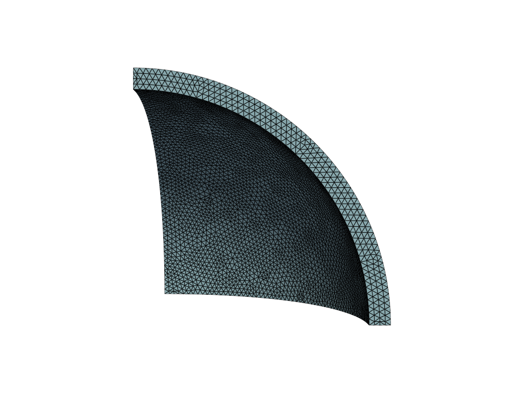
As a first step, we use the gmsh software to discretize (mesh) one octant of the background crust volume (see Figure 1). Meshing one octant of the background crust is sufficient to study the displacements, the strains, the stresses, and other physical properties. The rotational deformations of the anisotropic crust under consideration behave the same way in all of the octants because of the reflection symmetries about the , , and . Furthermore, meshing just one octant reduces the number of DoF, the memory consumption, and the computation time by about a factor of 8. In fact, it is this reduction in DoF that allows us to solve the discretized form of equation (33) directly, without having to resort to less accurate iterative solution methods. We allow the mesh to have second-order elements that have a maximum size close to m, and a minimum size that is much smaller than m. However, the bulk of the elements have sizes close to m. We force the meshing algorithm to produce elements that are a few times smaller than the maximum allowed size near the bottom and top interfaces ( and , respectively). The finite-element method solutions are very sensitive to size of the elements, specially to the sizes of the elements near the boundary layers. Hence, we expect that the reduction of element sizes near the solid-fluid interfaces will improve the accuracy of the solutions without incurring in a large computational cost. It is against this mesh that we obtain approximate solutions of the Eulerian displacement and its derived quantities (like the strains, the stresses, the small changes in density, and others).
After the mesh is crafted, we utilize FEniCSx 0.8.0 [44, 45, 46, 47], a high-performing and efficient finite-element method library, to solve the discretized form of equation (33) for both an anisotropic and an isotropic crust. The solutions for the isotropic and the anisotropic crust, which we call and , respectively, are found within the mesh elements using second-order Continuous-Garlerkin polynomials. Having and on all the nodes of the mesh allows the calculation of the strains, the stresses, the density perturbations, and all of the other physical properties of interest.
Once we find these solutions, we can calculate the raw ellipticity that the simulations output. In addition, we can quantify what the ellipticity of an isotropic NS is. We call this the residual ellipticity. The residual ellipticity is caused by the imperfect matching of the elements with the boundaries of the sphere octant and other errors associated with the finite-element method. Ideally, the residual ellipticity should be zero because a NS with an isotropic crust that is deformed by rotation is perfectly axisymmetric.
In order to obtain the raw ellipticity, we calculate the difference in the x-x and y-y components of the moment of inertia tensor across the volume of the NS (). However, only the volume of the solid crust contributes to the ellipticity. Therefore, the difference in the moments of inertia is given by
| (34) |
where , and . In addition, we calculate considering the z-z component of the moment of inertia tensor of the undeformed background star introduced in section III:
| (35) |
This is reasonable because is in the denominator of the ellipticity definition. Consequently, small material displacements and mass density perturbations result in negligible contributions from to the ellipticity. Notice that the evaluation of equation (35) does not require the usage of the finite-element method. We evaluate the expressions in equations (34) and (35) in just one octant of the crust, and then calculate the raw ellipticity. This is possible because the evaluation of expressions (34) and (35) give the same results for all of the octants. The raw ellipticity is given by
| (36) |
We apply these same steps to calculate the residual ellipticity. The only difference is that we need to evaluate equation (34) with replacing because the crust is isotropic (). The difference in moments of inertia for a NS with an isotropic crust is defined as
| (37) |
where , , and . The residual ellipticity is given by
| (38) |
In essence, the residual ellipticity is noise from the different components of the finite-element method. Therefore, it is convenient to define the physical ellipticity as
| (39) |
The physical ellipticity is the ellipticity that stems from crustal anisotropies and changes in rotation.
VI Results and Discussion
In this section, we present how the results of this work support our previous investigation on anisotropic neutron star crusts and CGW [2], and discuss some new findings.
In our previous work, we modeled the anisotropic crust of a rotating NS as a constant density, rotating thin disc. The simplicity of the problem allowed us to obtain a useful analytical expression for the ellipticity:
| (40) |
Here, is the mass of the crust, is the total mass of the NS, is the same average anisotropy parameter as in equation (27), is the initial rotational frequency, is the final rotational frequency, and is the relativistic Kepler rotational frequency. This ellipticity is the by-product of the anisotropy in the elastic stresses that build within the crust as the star spins up or down. The Kepler rotational frequency for a rotating NS is Hz. In this research work, the rotational Kepler frequency is Hz because we consider a non-relativistic canonical rotating NS with a polytropic EOS. Thus, the analytical estimate that we need to verify becomes
| (41) |
For a canonical 1.4 M⊙ and 10 km NS, the fraction of the crustal mass is . We assume that the NS is initially at rest ( Hz) and spins up to 10 % of ( Hz). Furthermore, we suppose that the crust has a modest average anisotropy of . The finite-element method yields the Eulerian displacement as the solution. The components of the displacement vector in spherical coordinates are shown in Figures 2-4. In these figures, , , and represent the displacements in spherical coordinates (,,), where is the radial coordinate, is the polar angle, and is the azimuthal angle. We only show the displacement components as functions of the polar angle because that is the strongest dependence. Notice that because of the material anisotropies.
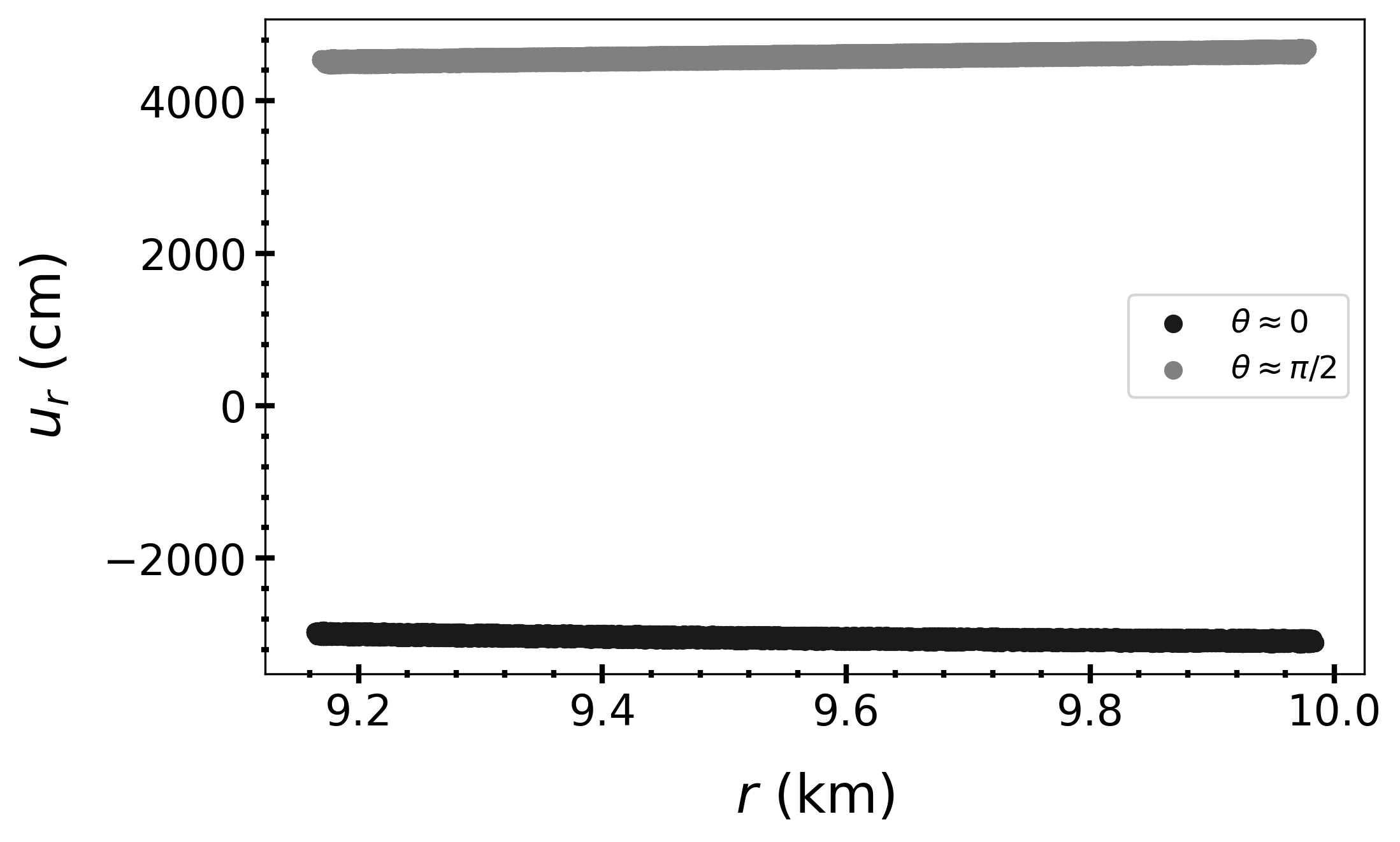
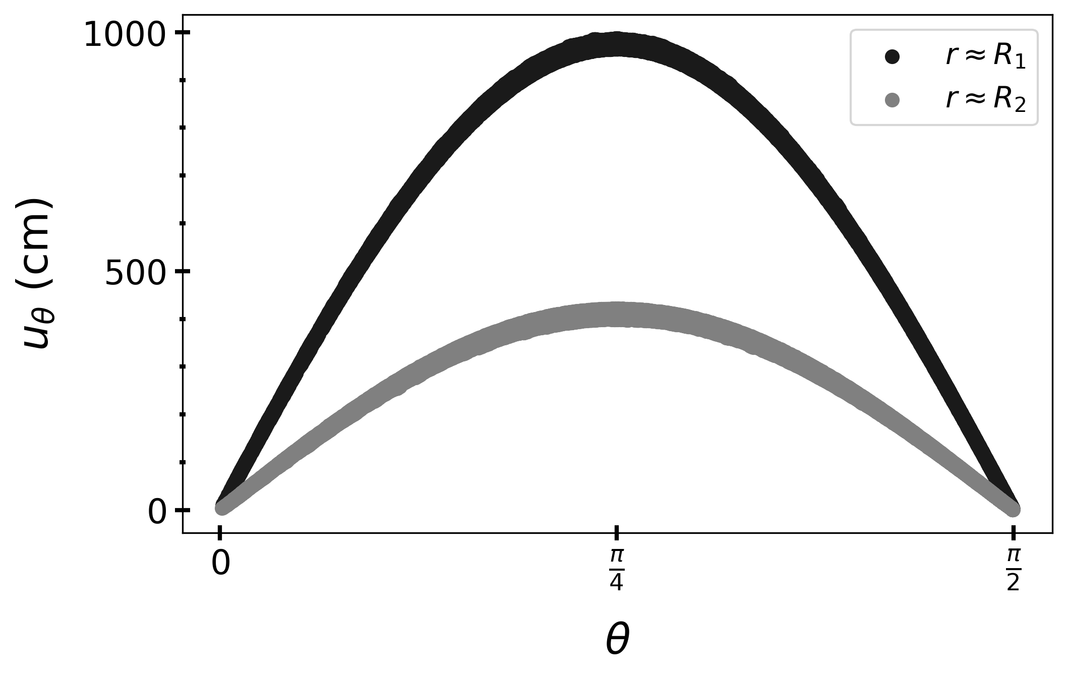
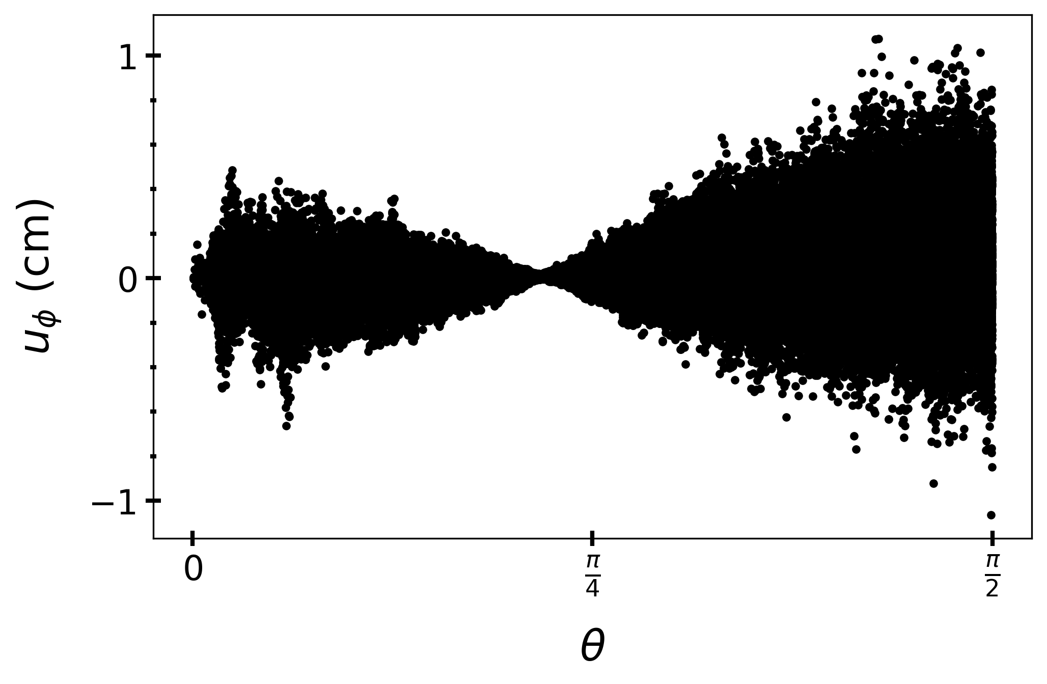
The evaluation of the analytical estimate of the ellipticity (equation (41)) gives . The ellipticity that our finite-element application gives (see equations (2), (34), and (35)) is , while the residual ellipticity is .
We can study how the ellipticity grows as one goes from the inside of the crust to its outside. Moreover, we can investigate how much the displacement components and the changes in density contribute to that ellipticity growth as the radius gets larger. To resolve these features, it is necessary to subtract the residual ellipticity contribution from the ellipticity contribution on each element. The results are given in Figures 5 and 6.
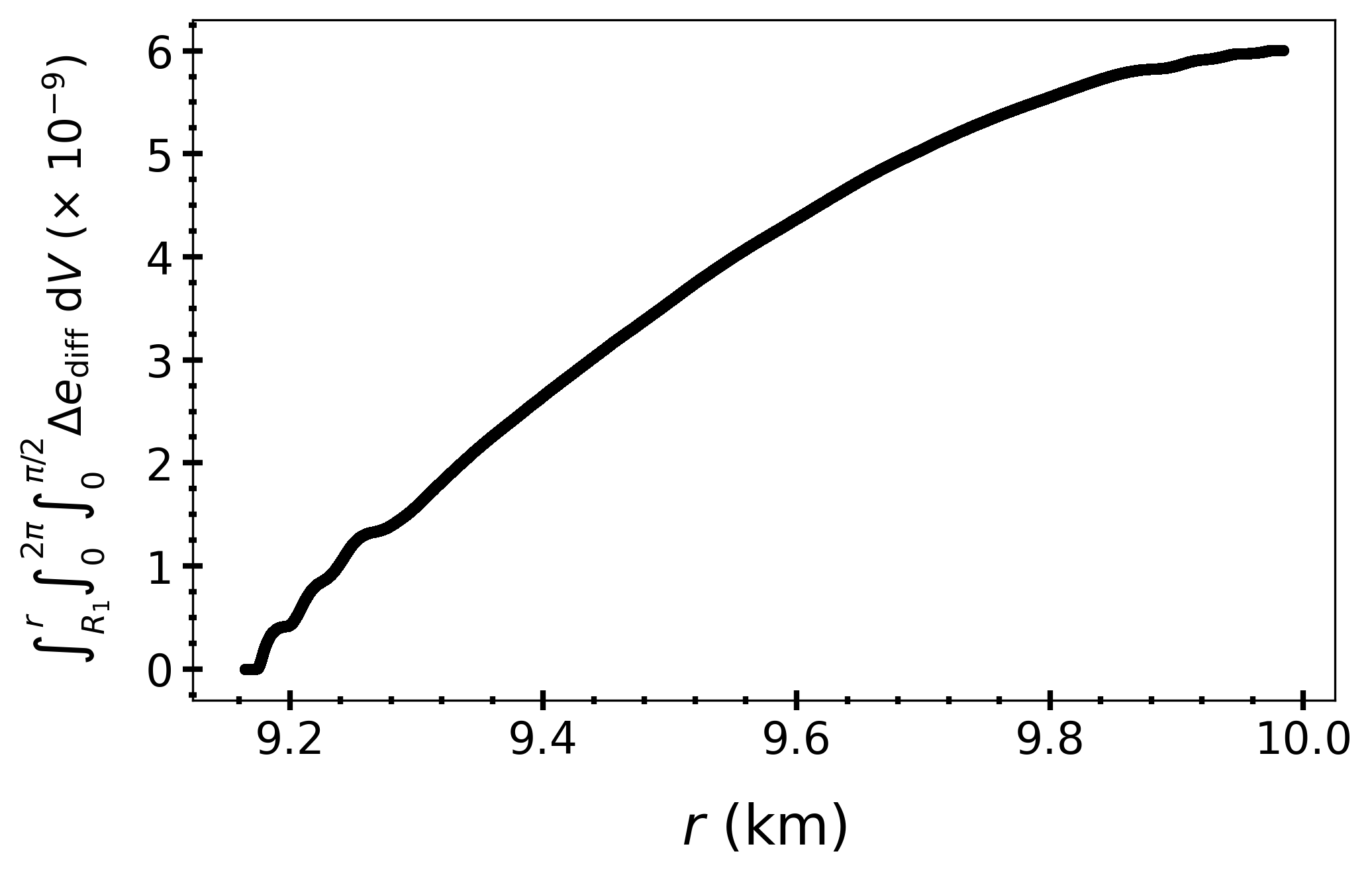
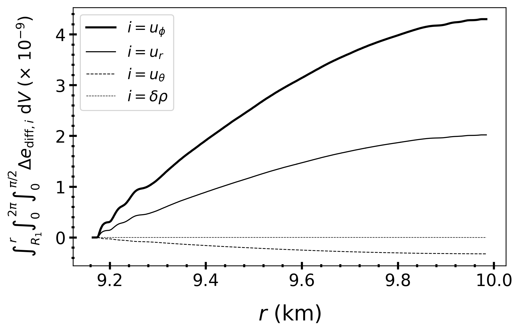
The integrals have an integration domain that encompasses the whole NS. However, our calculations were done using only one octant of the whole NS. These two calculations are equivalent, as explained above.
In Figure 6 the ’s are the various ellipticity contributions from each element. The diff subscript indicates that we take the difference between the ellipticity contribution from the anisotropic NS (the physical ellipticity) and the perfectly-axisymmetric NS (the residual ellipticity). The formulae from the different ’s are given by
| (42) |
| (43) |
| (44) |
| (45) |
| (46) |
Remember that is the distance from the rotation axis. The total ellipticity’s per-element contribution is given by , where terms of second order in are neglected.
Figure 5 seems to disagree with the ellipticity value that we mentioned above. Nonetheless, this is not a contradiction, as we are subtracting the residual ellipticity contribution from the ellipticity contribution at each element. Since the residual ellipticity if of the order of , this difference is expected.
The major contribution to the total ellipticity comes from the contribution, as we predicted in our previous work [2]. This is the main reason why our result agrees with our previous work. The second major contribution to the total ellipticity comes from . In our previous work, we predicted that the contribution from is much smaller than the contribution from . In contrast, in this work, the and ellipticity contributions are about the same order of magnitude. This difference is due to the density gradient that is taken into account in this work while neglected in our previous work, where we assume that the density is constant through the crust. The and contributions to the total ellipticity are much smaller. This is another reason why the ellipticity calculation in this work agrees with the estimate that was done in our previous work (see equations (40) and (41)).
In Figures 7 and 8, we confirm that the ellipticity scales linearly with the average anisotropy parameter and quadratically with for a NS that is initially at rest. This is the expected behavior that we infer from the analytical estimates expressed in equations (40) and (41). The slight deviation from perfect linearity between the ellipticity and the average anisotropy parameter comes from the non-linear dependence of the strain on . These non-linearities are negligible when .
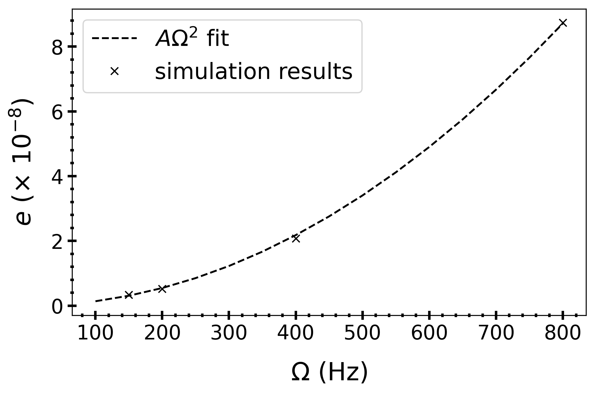
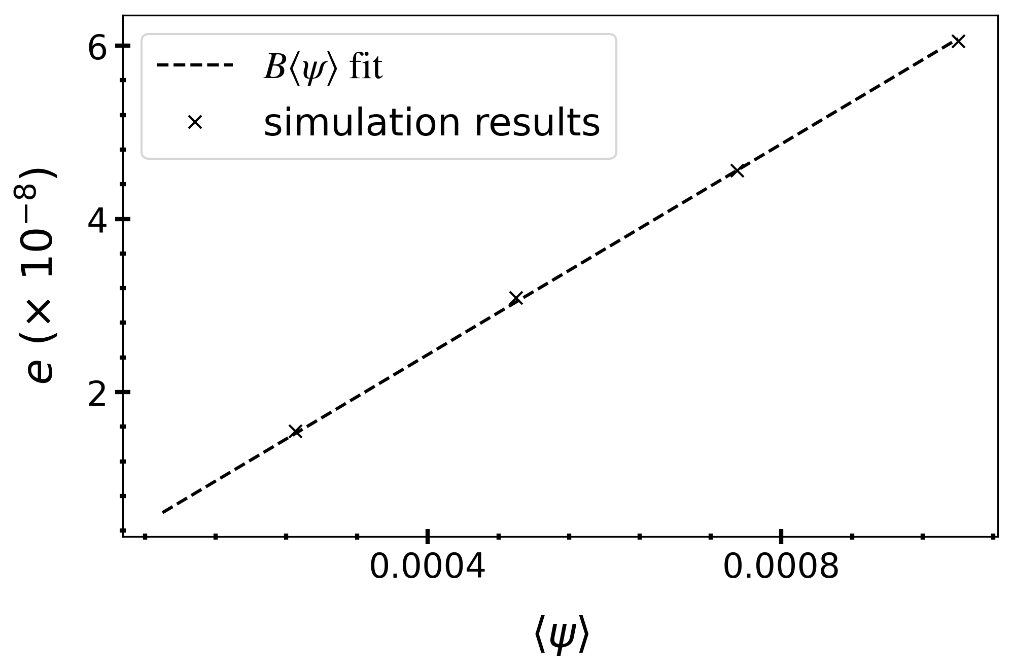
Therefore, we can conclude that equations (40) and (41) are valid analytical estimates of the ellipticity of a slightly anisotropic NS crust that is subject to a small change in rotational frequency. The results of many simulations are given in Table 1. This has several consequences that were explained in detail in our previous work [2]. We briefly summarize these consequences here.
| Vary | (Hz) | (g cm-3) | element size (m) | ||||
|---|---|---|---|---|---|---|---|
| 150 | 100 | ||||||
| 200 | 100 | ||||||
| 400 | 100 | ||||||
| 800 | 100 | ||||||
| 220 | 100 | ||||||
| 220 | 100 | ||||||
| 220 | 100 | ||||||
| 220 | 100 | ||||||
| 220 | 100 | ||||||
| 220 | 100 | ||||||
| 220 | 100 | ||||||
| 220 | 100 | ||||||
| element size | 220 | 150 | |||||
| 220 | 125 | ||||||
| 220 | 100 |
First, an anistropic crust can produce a detectable ellipticity if a rapidly rotating NS is close-by (see Figure 4 from reference [3] and compare with the ellipticity of that we obtain from a slighlty anisotropic NS that spins up from rest to 220 Hz). Second, an anisotrpic crust can explain the torque balance that can limit the rotational frequency of accreting milisecond pulsars [36]. Third, an anisotropic crust can explain the evidence of a minimum ellipticity observed for a population of milisecond pulsars [48]. Finally, an anisotropic crust implies that NS mountains have an evolving braking index that can be very different from 5.
Under the approximation of the static background star described in section III, we can obtain valid approximations for a spinning down NS, as long as . If a NS is initially spinning at 220 Hz, spins down to rest, and have an average anisotropy of , then the magnitudes of all of the ellipticities and ellipiticity contributions will be the same as the ones presented for the analogous spinning up star that we have presented in this section. The only difference is that the results will have different signs.
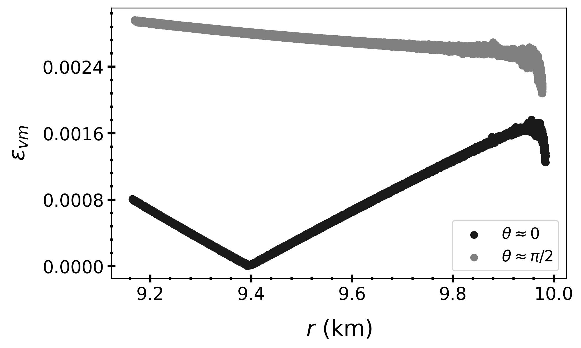
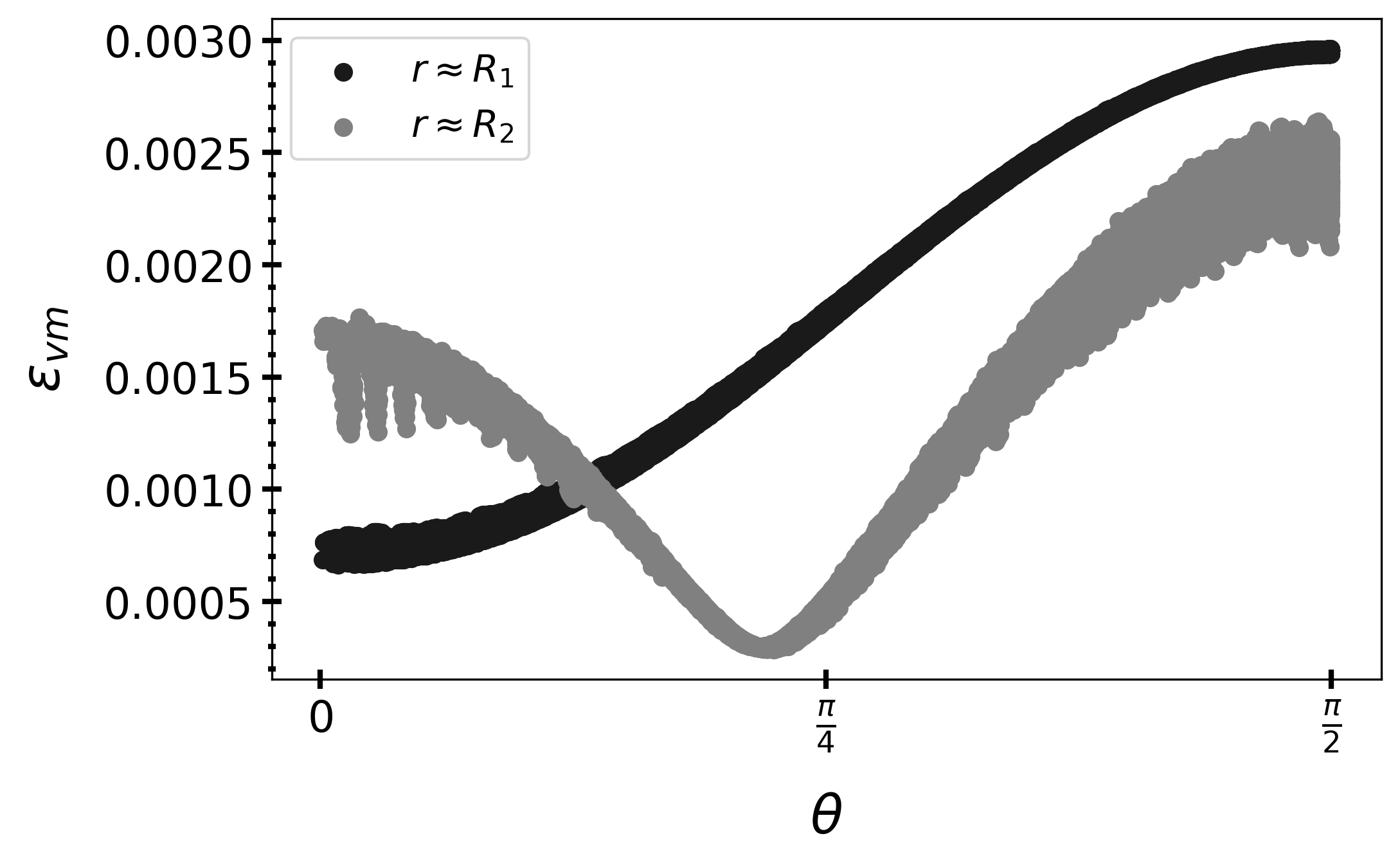
The von-Mises strain is defined as
| (47) |
In spherical coordinates, the von-Mises strain can be written as
| (48) |
The NS that spins up from rest to 220 Hz has the von-Mises strain field shown in Figures 9 and 10. The von-Mises strain is largest at the bottom of the crust () and at the equator (). This is what Franco, Link and Epstein [38] found. They used a constant-density spheroid with a solid crust atop of a liquid fluid to study quaking NSs. Since , the results of our more realistic model support the conclusions of Franco, Link and Epstein [38] and Fattoyev and Horowitz [33]. Since starquakes start at the crustal bottom, where the crust is densest and strongest, starquakes induced by crust breaking can release sufficient energy to explain some observations, including changes in the pulse profiles (glitches), luminosity increases, and limiting rotational frequencies that are related to crustal strengths. Furthermore, Franco, Link, and Epstein and Horowitz and Fattoyev concluded that crust breaking may cause asymmetric re-distributions of matter that can couple with the rotation of NSs to radiate CGWs. A detailed consideration of crust breaking, starquakes, and observational consequences is left for a future study.
VII Conclusions
In this research work, we have applied the finite-element method in realistic three-dimensional NS models to study the ellipticities induced by changes in rotational rate coupled with anisotropies in the crust.
Solid crusts with modest material anisotropies can be stressed by small changes in rotational rate to source ellipticities that are interesting because of various reasons. These ellipticities scale linearly with the small degree of anisotropy in the solid crust and quadratically with the difference between the squares of the final and initial rotational frequecies. Ground-based detectors might be sensitive to these ellipticities if NSs are rapidly spinning and nearby [3]. Moreover, anisotropic ellipticities can produce the torque balance that may explain accreting millisecond pulsar observations and the minimum ellipticities that might be present in populations of milisecond pulsars [36, 39, 2].
Our model suggests that the crust breaks at the bottom first. This implies that starquakes that are induced by crust breaking may explain some observations, including glitches, changes in luminosity, limiting rotational frequencies that are related to the strength of the crust, and an asymmetric re-distribution of matter that can couple to the rotation of NSs to radiate CGWs [38, 39]. These considerations will be studied in detail in future work.
Acknowledgements.
We thank the developers of FEniCSx for their help during the development and implementation of our finite-element simulations. This work is partially supported by the US Department of Energy grant DE-FG02-87ER40365 and National Science Foundation grant PHY-2116686.References
- [1] Thanh-Son Phạm and Hrvoje Tkalčić. Up-to-fivefold reverberating waves through the earth’s center and distinctly anisotropic innermost inner core. Nature Communications, 14(1):754, 2023.
- [2] J. A. Morales and C. J. Horowitz. Anisotropic neutron star crust, solar system mountains, and gravitational waves, 2023.
- [3] R. Abbott et al. Search for continuous gravitational wave emission from the Milky Way center in O3 LIGO-Virgo data. Phys. Rev. D, 106:042003, Aug 2022.
- [4] B. P. Abbott et al. Observation of Gravitational Waves from a Binary Black Hole Merger. Phys. Rev. Lett., 116:061102, Feb 2016.
- [5] B. P. Abbott, R. Abbott, T. D. Abbott, S. Abraham, F. Acernese, K. Ackley, C. Adams, R. X. Adhikari, V. B. Adya, and C. Affeldt. GW170817: Observation of Gravitational Waves from a Binary Neutron Star Inspiral. Phys. Rev. Lett., 119:161101, Oct 2017.
- [6] Gabriella Agazie et al. The NANOGrav 15 yr Data Set: Evidence for a Gravitational-wave Background. The Astrophysical Journal Letters, 951(1):L8, jun 2023.
- [7] Antoniadis, J. et al. The second data release from the European Pulsar Timing Array - III. Search for gravitational wave signals. A&A, 678:A50, 2023.
- [8] Heng Xu et al. Searching for the Nano-Hertz Stochastic Gravitational Wave Background with the Chinese Pulsar Timing Array Data Release I. Research in Astronomy and Astrophysics, 23(7):075024, jun 2023.
- [9] Daniel J. Reardon et al. Search for an Isotropic Gravitational-wave Background with the Parkes Pulsar Timing Array. The Astrophysical Journal Letters, 951(1):L6, jun 2023.
- [10] Nils Andersson and Fabian Gittins. Formulating the r-mode Problem for Slowly Rotating Neutron Stars. The Astrophysical Journal, 945(2):139, mar 2023.
- [11] Fabian Gittins and Nils Andersson. The r-modes of slowly rotating, stratified neutron stars. Monthly Notices of the Royal Astronomical Society, 521(2):3043–3057, 03 2023.
- [12] Fabian Gittins. Gravitational waves from neutron-star mountains. Classical and Quantum Gravity, 41(4):043001, jan 2024.
- [13] T J Hutchins and D I Jones. Gravitational radiation from thermal mountains on accreting neutron stars: sources of temperature non-axisymmetry. Monthly Notices of the Royal Astronomical Society, 522(1):226–251, 03 2023.
- [14] Pedro H B Rossetto, Jörg Frauendiener, Ryan Brunet, and Andrew Melatos. Magnetically confined mountains on accreting neutron stars in general relativity. Monthly Notices of the Royal Astronomical Society, 526(2):2058–2066, 09 2023.
- [15] Swarnim Shirke, Suprovo Ghosh, Debarati Chatterjee, Laura Sagunski, and Jürgen Schaffner-Bielich. R-modes as a new probe of dark matter in neutron stars. Journal of Cosmology and Astroparticle Physics, 2023(12):008, dec 2023.
- [16] B. Haskell. R-modes in neutron stars: Theory and observations. International Journal of Modern Physics E, 24(09):1541007, 2015.
- [17] Mark G. Alford, Simin Mahmoodifar, and Kai Schwenzer. Viscous damping of r-modes: Small amplitude instability. Phys. Rev. D, 85:024007, Jan 2012.
- [18] Ruxandra Bondarescu, Saul A. Teukolsky, and Ira Wasserman. Spinning down newborn neutron stars: Nonlinear development of the -mode instability. Phys. Rev. D, 79:104003, May 2009.
- [19] Gianluca Pagliaro, Maria Alessandra Papa, Jing Ming, Jianhui Lian, Daichi Tsuna, Claudia Maraston, and Daniel Thomas. Continuous Gravitational Waves from Galactic Neutron Stars: Demography, Detectability, and Prospects. The Astrophysical Journal, 952(2):123, jul 2023.
- [20] P. B. Covas, R. Prix, and J. Martins. A new framework to follow up candidates from continuous gravitational-wave searches, 2024.
- [21] A. Ashok, P. B. Covas, R. Prix, and M. A. Papa. Bayesian -statistic-based parameter estimation of continuous gravitational waves from known pulsars. Phys. Rev. D, 109:104002, May 2024.
- [22] Rafel Jaume, Rodrigo Tenorio, and Alicia M. Sintes. Assessing the similarity of continuous gravitational-wave signals to narrow instrumental artifacts. Universe, 10(3), 2024.
- [23] Orion Sauter, Ninad Bhagwat, John Conklin, and D. B. Tanner. Identification of resonant frequencies in ligo-like suspension with finite-element modeling. Phys. Rev. D, 109:064033, Mar 2024.
- [24] Johanna L. Miller. Frequency-dependent squeezing makes LIGO even more sensitive. Physics Today, 77(1):13–16, 01 2024.
- [25] Prasanna M. Joshi and Reinhard Prix. Novel neural-network architecture for continuous gravitational waves. Phys. Rev. D, 108:063021, Sep 2023.
- [26] P. V. Padmanabh et al. Discovery and timing of ten new millisecond pulsars in the globular cluster Terzan 5, 2024.
- [27] J D Turner et al. TRAPUM search for pulsars in supernova remnants and pulsar wind nebulae - I. Survey description and initial discoveries. Monthly Notices of the Royal Astronomical Society, page stae1300, 05 2024.
- [28] Benjamin J. Owen, Lee Lindblom, Luciano Soares Pinheiro, and Binod Rajbhandari. Improved Upper Limits on Gravitational-wave Emission from NS 1987A in SNR 1987A. The Astrophysical Journal Letters, 962(2):L23, feb 2024.
- [29] B. Steltner, M. A. Papa, H.-B. Eggenstein, R. Prix, M. Bensch, B. Allen, and B. Machenschalk. Deep Einstein@Home All-sky Search for Continuous Gravitational Waves in LIGO O3 Public Data. The Astrophysical Journal, 952(1):55, jul 2023.
- [30] J. Ming, M. A. Papa, H.-B. Eggenstein, B. Machenschalk, B. Steltner, R. Prix, B. Allen, and O. Behnke. Results From an Einstein@Home Search for Continuous Gravitational Waves From G347.3 at Low Frequencies in LIGO O2 Data. The Astrophysical Journal, 925(1):8, jan 2022.
- [31] R. Abbott, H. Abe, F. Acernese, K. Ackley, N. Adhikari, R. X. Adhikari, V. K. Adkins, and V. B. Adya. Searches for gravitational waves from known pulsars at two harmonics in the second and third ligo-virgo observing runs. The Astrophysical Journal, 935(1):1, may 2022.
- [32] M.E. Caplan, A.S. Schneider, and C.J. Horowitz. Elasticity of Nuclear Pasta. Phys. Rev. Lett., 121:132701, Sep 2018.
- [33] C.J. Horowitz and K. Kadau. Breaking Strain of Neutron Star Crust and Gravitational Waves. Phys. Rev. Lett., 102:191102, May 2009.
- [34] Fabian Gittins and Nils Andersson. Modelling neutron star mountains in relativity. Monthly Notices of the Royal Astronomical Society, 507(1):116–128, 07 2021.
- [35] J A Morales and C J Horowitz. Neutron star crust can support a large ellipticity. Monthly Notices of the Royal Astronomical Society, 517(4):5610–5616, 10 2022.
- [36] G. Ushomirsky, C. Cutler, and L. Bildsten. Deformations of Accreting Neutron Star Crusts and Gravitational Wave Emission. MNRAS, 319:902–932, Aug 2000.
- [37] Roxburgh, I. W. 2-dimensional models of rapidly rotating stars I. Uniformly rotating zero age main sequence stars . A&A, 428(1):171–179, 2004.
- [38] Lucia M. Franco, Bennett Link, and Richard I. Epstein. Quaking Neutron Stars. The Astrophysical Journal, 543(2):987, nov 2000.
- [39] F. J. Fattoyev, C. J. Horowitz, and Hao Lu. Crust breaking and the limiting rotational frequency of neutron stars, 2018.
- [40] William Robert Gittins Fabian. Gravitational waves from deformed neutron stars: mountains and tides. PhD thesis, Southampton U., 2021.
- [41] C.J. Krüger, W.C.G. Ho, and N. Andersson. Seismology of adolescent neutron stars: Accounting for thermal effects and crust elasticity. Phys. Rev. D, 92:063009, Sep 2015.
- [42] Pauli Virtanen, Ralf Gommers, Travis E. Oliphant, Matt Haberland, Tyler Reddy, David Cournapeau, Evgeni Burovski, Pearu Peterson, Warren Weckesser, Jonathan Bright, Stéfan J. van der Walt, Matthew Brett, Joshua Wilson, K. Jarrod Millman, Nikolay Mayorov, Andrew R. J. Nelson, Eric Jones, Robert Kern, Eric Larson, C J Carey, İlhan Polat, Yu Feng, Eric W. Moore, Jake VanderPlas, Denis Laxalde, Josef Perktold, Robert Cimrman, Ian Henriksen, E. A. Quintero, Charles R. Harris, Anne M. Archibald, Antônio H. Ribeiro, Fabian Pedregosa, Paul van Mulbregt, and SciPy 1.0 Contributors. SciPy 1.0: Fundamental Algorithms for Scientific Computing in Python. Nature Methods, 17:261–272, 2020.
- [43] Charles R. Harris, K. Jarrod Millman, Stéfan J. van der Walt, Ralf Gommers, Pauli Virtanen, David Cournapeau, Eric Wieser, Julian Taylor, Sebastian Berg, Nathaniel J. Smith, Robert Kern, Matti Picus, Stephan Hoyer, Marten H. van Kerkwijk, Matthew Brett, Allan Haldane, Jaime Fernández del Río, Mark Wiebe, Pearu Peterson, Pierre Gérard-Marchant, Kevin Sheppard, Tyler Reddy, Warren Weckesser, Hameer Abbasi, Christoph Gohlke, and Travis E. Oliphant. Array programming with NumPy. Nature, 585(7825):357–362, September 2020.
- [44] Igor A. Baratta, Joseph P. Dean, Jørgen S. Dokken, Michal Habera, Jack S. Hale, Chris N. Richardson, Marie E. Rognes, Matthew W. Scroggs, Nathan Sime, and Garth N. Wells. DOLFINx: the next generation FEniCS problem solving environment. preprint, 2023.
- [45] Matthew W. Scroggs, Jørgen S. Dokken, Chris N. Richardson, and Garth N. Wells. Construction of arbitrary order finite element degree-of-freedom maps on polygonal and polyhedral cell meshes. ACM Transactions on Mathematical Software, 48(2), 2022.
- [46] Matthew W. Scroggs, Igor A. Baratta, Chris N. Richardson, and Garth N. Wells. Basix: a runtime finite element basis evaluation library. Journal of Open Source Software, 7(73):3982, 2022.
- [47] Martin S. Alnaes, Anders Logg, Kristian B. Ølgaard, Marie E. Rognes, and Garth N. Wells. Unified form language: A domain-specific language for weak formulations of partial differential equations. ACM Transactions on Mathematical Software, 40, 2014.
- [48] G. Woan, M. D. Pitkin, B. Haskell, D. I. Jones, and P. D. Lasky. Evidence for a minimum ellipticity in millisecond pulsars. The Astrophysical Journal Letters, 863(2):L40, aug 2018.