Adapting to Reality: Over-the-Air Validation of AI-Based Receivers Trained with Simulated Channels
Abstract
Recent research has shown that integrating artificial intelligence (AI) into wireless communication systems can significantly improve spectral efficiency. However, the prevalent use of simulated radio channel data for training and validating neural network-based radios raises concerns about their generalization capability to diverse real-world environments. To address this, we conducted empirical over-the-air (OTA) experiments using software-defined radio (SDR) technology to test the performance of an NN-based orthogonal frequency division multiplexing (OFDM) receiver in a real-world small cell scenario. Our assessment reveals that the performance of receivers trained on diverse 3GPP TS38.901 channel models and broad parameter ranges significantly surpasses conventional receivers in our testing environment, demonstrating strong generalization to a new environment. Conversely, setting simulation parameters to narrowly reflect the actual measurement environment led to suboptimal OTA performance, highlighting the crucial role of rich and randomized training data in improving the NN-based receiver’s performance. While our empirical test results are promising, they also suggest that developing new channel models tailored for training these learned receivers would enhance their generalization capability and reduce training time. Our testing was limited to a relatively narrow environment, and we encourage further testing in more complex environments.
I Introduction
By leveraging artificial intelligence (AI) in the physical layer processing of radio receivers, wireless communication systems have the potential to achieve significantly better spectral efficiency compared to conventional heuristic methods [1, 2]. However, these learned receivers require extensive data for effective training. While radio channel simulations offer a practical source of training data, using simulations for receiver model validation creates uncertainty regarding how well these receivers can perform in real-world scenarios. The concern is that these AI-assisted radios might become biased towards the characteristics of the simulated environments, compromising their ability to generalize to real-world radio environments.
Validating the over-the-air (OTA) performance of AI-assisted receivers trained with radio channel simulations is crucial. However, limited literature addresses these learned receivers’ testing with OTA measurements, highlighting a significant gap. To bridge this gap, we built an end-to-end orthogonal frequency division multiplexing (OFDM) system with software-defined radios (SDRs) for OTA measurements [3]. We utilized DeepRx, a convolutional neural network (CNN)-based OFDM receiver, and trained it using diverse 3GPP TS38.901-based channel model simulations and parameters [4, 5]. Subsequently, OTA data collection was conducted in a controlled environment resembling a cellular micro- or small-cell setup, and the CNN-based receiver performance was compared with a conventional OFDM receiver using a Least Squares (LS)-based channel estimator and Linear Minimum Mean Square Error (LMMSE) equalization.
This research assesses the performance of the DeepRx receiver trained with various channel models and parameter settings compared to the conventional LS/LMMSE receiver in our OTA test environment. It thereby evaluates the DeepRx’s potential to generalize to real-world scenarios. It also reveals the importance of real-world measurements for model validation and the need for diverse simulated channels for training the receivers.
The remainder of this paper is organized as follows: Section II summarizes the related work, and Section III outlines the research methodology and system model. The measurement results are then reported in Section IV. Section V discusses the key observations, and finally, the conclusions are drawn in Section VI
II Related Work
Integrating machine learning and deep learning into the physical layer processing of wireless communication systems has generated significant interest. In [1], deep learning is introduced for the physical layer (PHY), offering a new perspective on how AI can enhance communication system design and performance. Ye et al. [6] demonstrate the power of deep learning for channel estimation and signal detection in OFDM systems, highlighting significant performance gains over traditional methods. Huang et al. [2] and Wang et al. [7] further discuss the opportunities and challenges associated with deploying deep learning techniques for PHY processing. Meanwhile, the role of machine learning in optimizing 5G and 6G systems is emphasized in [8], indicating the broader implications of AI in current and next-generation networks. At the forefront of applying these concepts is the DeepRx model [4], which exemplifies the implementation of a fully convolutional deep learning receiver based on ResNet structure [9]. This work proves the usefulness of deep learning in improving receiver performance and establishes the foundation for our study.
Our study leverages prior work using SDRs for over-the-air measurements to transition from theoretical simulations to over-the-air testing. Robust synchronization in SDR systems is crucial. A synchronization procedure using chirp signals, demonstrating high accuracy with multipath channels, is introduced in [10]. The Online Wireless Lab (OWL) Testbed at TU Dresden, based on SDR radios and described in [11], offers a flexible, real-time test infrastructure for SDR systems, providing remote access to valuable OTA measurements in indoor and outdoor environments. Additionally, the implementation of Non-Orthogonal Multiple Access (NOMA) systems using SDR is explored in [12], showcasing an end-to-end system implementation with SDR for physical layer processing.
This study builds upon existing research that has primarily explored the area in simulated environments by focusing on the real-world validation of AI-assisted radios.
III Methodology
III-A OFDM System Model
The block diagram of the implemented OFDM processing chain is depicted in Figure 1. Except for incorporating the SDR for OTA measurements, the system model architecture closely adheres to the one outlined in [4].

III-A1 Conventional Receiver
The receiver architecture in our traditional OFDM system implementation follows a conventional sequence of operations after the receiver FFT block: LS channel estimation, LMMSE equalization, and symbol-to-soft-bit demapping.
In particular, the received signal over the -th subcarrier and -th OFDM symbol is modeled as:
| (1) |
where is the received signal, is the transmitted signal, is the channel response, and is the additive noise. Moreover, and denote the numbers of receive and transmit antennas, respectively.
The LS channel estimation measured from pilot signals is calculated as
| (2) |
where is an array consisting of the transmitted pilot symbols of all spatial streams for pilot index and H denotes Hermitian transpose. The channel is then interpolated between the pilots, which yields the complete channel estimate across all resource elements as , where denotes the interpolation function.
The LMMSE equalized symbols are then calculated as
| (3) |
where is the estimated noise variance and is the identity matrix.
After this, the demapper maps the equalized symbols to Log-Likelihood Ratios (LLRs), which represent soft estimates of the received bits. For each received symbol of the equalized symbol vector , the LLR of the -th bit is given by:
| (4) |
where denotes the -th bit of the corresponding symbol.
III-A2 ML Receiver
In our NN-based implementation, in contrast to the above-defined conventional architecture, the processing blocks in the receiver are replaced by a fully convolutional neural network (CNN), for which we employ ResNet structure [9]. The input to the NN is the received IQ signal for the whole TTI, and the output consists of the LLRs for all bits in the TTI. The NN is trained by optimizing cross-entropy loss between all ground truth bits and output LLRs. For further details about the NN-based DeepRx receiver, we refer the reader to [4].
III-B Numerology and Parameters
The employed parameters are shown in Table I. The choice of operating frequency for our OFDM system was guided by license availability. Hence, despite common usage scenarios favoring higher frequencies, we settled on 434 MHz for compliance with regulations.
| Measurement-only | |
|---|---|
| Center frequency | 433.92MHz |
| Bandwidth | 1.55MHz |
| Antenna gains [TX, RX] | [10 dB, 0 dB] |
| Peak TX Power | 5 dBm |
| Mean TX PSD | -13 dBm / 100kHz |
| Upsampling/Decimation Factor | 16 |
| Simulation-only | |
| Simulation environment | NVIDIA Sionna [13] |
| SNR range | 10 dB to 35 dB |
| Channel models | All TDL and CDL, UMa, UMi |
| Generic speed range | 0 m/s to 30 m/s |
| Generic delay spread range | 50ns to 1000ns |
| Speed slow range | 0 m/s to 3 m/s |
| Speed medium range | 3 m/s to 10 m/s |
| Speed fast range | 10 m/s to 30 m/s |
| DS very short range | 50 ns to 200 ns |
| DS short range | 200ns to 500ns |
| DS medium range | 500ns to 2 µs |
| DS long range | 2 µs to 5 µs |
| Common | |
| Modulation | OFDM 64QAM |
| FFT size [TX, RX] | [128, 128] |
| Subcarriers | 100 |
| Subcarrier spacing | 15kHz |
| Cyclic prefix | 6 |
| Pilot configuration | Every 4th SC, in 2nd symbol |
| Synchronization | Maximum preamble correlation |
| System | 1T1R SISO |
III-C Radio Channel Simulation Algorithms
The 3rd Generation Partnership Project (3GPP) developed statistical radio channel models that were used for training the DeepRx receiver as indicated in Table I [5]. For increased diversity of radio channels, we also employed a randomized model that randomly selects one of the TDL and CDL model variants ranging from A to E for each iteration.
Table I shows the simulated speed and delay spread ranges. The Generic speeds and delay spread ranges were used in all scenarios, except when the objective was to isolate the impact of these parameters. Then, the parameter ranges were split into narrower segments. The base model selected for the parameter impact tests was TDL-B as its performance is good with Generic speed and delay spread ranges when validated against OTA data.
III-D Use of Software-Defined Radio (SDR) Device
Our over-the-air radio transmission tests rely on two SDRs. The setup for receiving included an omnidirectional antenna connected to a 30 dB Low Noise Amplifier (LNA), which in turn was connected to the SDR’s RX port via a coaxial cable. With a length of around 15 m, the cable was long enough for an operator to move around the building during testing. The transmitting antenna was placed on a six-meter-high tower. It was connected to the SDR’s TX port via a low pass filter and coaxial cable. Figure 2 depicts the antennas and one of the two SDRs. The intention behind this arrangement was to mimic a small cell environment with outdoor BTS and indoor UE.
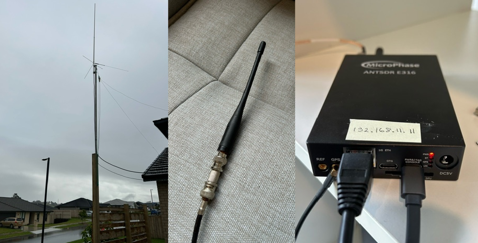
In our tests, synchronization was achieved by utilizing a preamble. To accurately determine the starting point of transmissions, a Zadoff-Chu sequence with a length of 100 was generated. We employed GPS-disciplined oven-controlled crystal oscillators (OCXOs) to maintain frequency accuracy and stability. Up-sampling and decimation were used for higher timing accuracy and improved reception.
As the utilized radio spectrum is shared, an initial verification was conducted to ensure the absence of interference. Also, during the data collection, no interference was detected; however, the possibility of brief, narrow-band, low-power interference cannot be entirely excluded.
III-E SDR Radio Channel Dataset Creation
III-E1 SDR Data Collection
The data collection process was made with two distinct methods. The first method involved gathering data while systematically walking through each room in a steel-roofed, single-story brick building. The second method involved running through the same rooms while swinging the antenna in the air to create faster variations in the collected radio channels. During the data collection, we recorded the original bit stream, the QAM IQ symbols received from the SDR receiver after synchronization and DFT, and the wideband SINR measurements per TTI basis. While the interference plus noise power was measured by averaging the power of the 500 unmodulated symbols inserted between successive TTIs, the signal power was measured as the average of the modulated symbols.
III-E2 SDR Datasets
A validation dataset of 500 TTIs was collected to monitor the model loss during training, and the data was collected by walking. Two further datasets were constructed for testing the performance of the trained models: dataset A consisting of 12000 TTIs, where the data was collected by walking, and dataset B consisting of 3000 TTIs, where the data was collected while running and swinging the antenna in the air.
III-F ML model training Procedure
Training parameters are summarized in Table II. Note that each training sample was generated independently, and no samples were re-used in the training, which means that the model cannot overfit but may still be susceptible to distribution mismatch between training and validation. The training was halted manually once the models did not improve further. While this required around 50000 iterations for most models, the model trained with randomly selected TDL/CDL channel model variants improved until approximately 150000 iterations. Apart from the abovementioned parameters, the training procedure followed the one described in [4].
| Batch Size | 28 |
|---|---|
| Initialization | He normal |
| Optimizer | AdamW, weight decay |
| Loss Function | EbNo weighted Binary Cross-Entropy (BCE) |
| Learning rate | Exponential. Start , decay rate 0.6 every 8000 iterations. Minimum learning rate is |
| Training dataset | Created on the fly, infinite. |
| Validation dataset | SDR generated, walking, 500 TTIs. |
| Testing Dataset A | SDR generated, walking, 12000 TTIs |
| Testing dataset B | SDR generated, running, 3000 TTIs |
III-G Performance Evaluation Criteria
The training phase involved monitoring the BCE loss on the simulated training and measured validation data. The performance of the final model was analyzed by comparing the BER with respect to SINR, using LS/LMMSE performance on the same test dataset as a benchmark.
IV Results
The final performance of the DeepRx receiver, trained with various 3GPP TS38.901-based models and parameter settings, was validated through OTA measurements. The average RMS delay spread in the test dataset was 105 ns. Below, we present the performance results of DeepRx models trained under various channel models and parameter configurations.
IV-A Channel Models
First, we consider the performance of DeepRx, which was trained with different channel models. The performance is evaluated with dataset A collected by walking.
IV-A1 3GPP TS38.901 TDL, UMa and UMi channel models
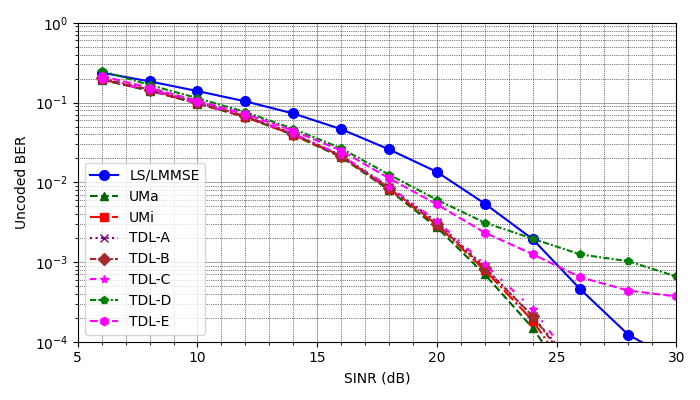
Figure 3 illustrates the performance of NN receivers trained with TDL-A to TDL-E using Generic speed and delay spread ranges (see Table I), UMa and UMi models. During training, the simulated speed parameter ranged randomly from 0 m/s to 30 m/s, while the delay spread varied from 50 ns to 1 µs. Notably, LS/LMMSE is surpassed in performance by DeepRx trained with any channel models except TDL-D and TDL-E, for which performance was inferior in the higher SINR region. These TDL-D and TDL-E models represent line-of-sight scenarios and, therefore, did not capture the measurement scenario effectively, resulting in poor performance. UMa and UMi-trained models both performed well.
IV-A2 3GPP TS38.901 CDL and the randomly selected channel models
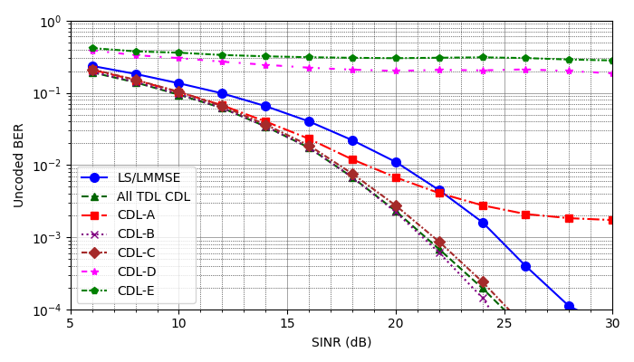
Figure 4 depicts the performance results of DeepRx models trained with CDL-A to CDL-E and a model trained with randomly selected TDL and CDL variants for each training iteration. This randomly generated model is referred to in the figures as ALL TDL/CDL. Generic speed and delay spread ranges in Table I were used.
While CDL models B and C exhibit substantial performance improvements, CDL-A performs poorly. CDL-D and E, representing line-of-sight channels, failed the over-the-air tests despite converging well during training. The model trained with random CDL and TDL channels performs exceptionally well, similar to CDL-B and TDL-B.
IV-B Delay Spread and Speed
Then, we consider the performance of DeepRx, which is trained with different channel model parameters.
IV-B1 Delay Spread
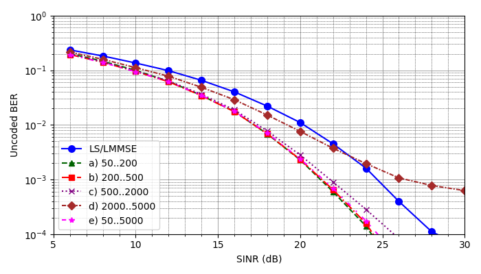
Figure 5 displays the performance outcomes for various delay spread settings for TDL-B. The testing dataset A was used. The results align with expectations, as shorter delays outperform longer delays, reflecting the actual measurement environment. Remarkably, DeepRx trained over an extensive range from 50 ns to 5 µs performs as well as the top-performing models trained with narrower delay spread ranges matching the measurement conditions.
IV-B2 Speed
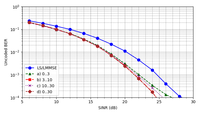
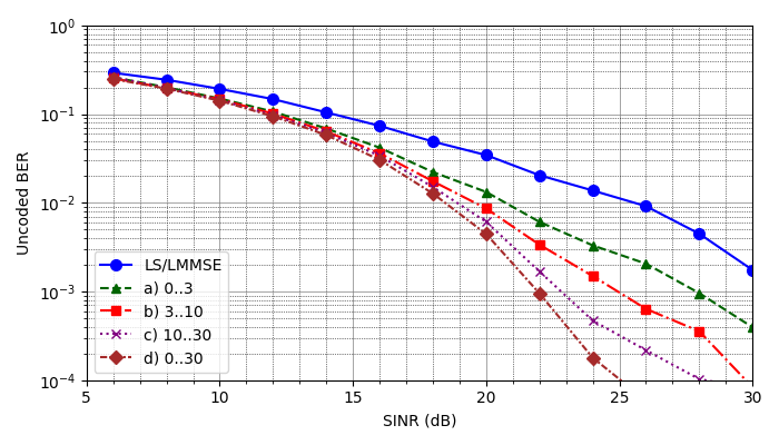
Figure 6 depicts the performance outcomes of DeepRx when trained with the TDL-B model at different simulated speeds. For testing dataset A, despite the measurements being conducted by walking at well below three m/s speed, the performance of DeepRx models trained at similar simulated speeds performed less effectively than those trained at higher simulated speeds. The highest performance was achieved by training the model across a broad speed range of 0 m/s to 30 m/s. Similar behavior was observed for dataset B, conducted by running and swinging the antenna. The performance of the DeepRx model trained with a broad range of speeds from 0 m/s to 30 m/s is comparable to the best-performing models in our tests, whereas models trained at speeds closer to the actual measurement speed were inferior. Furthermore, the performance of LS/LMMSE was notably degraded.
V Discussion
The over-the-air test results demonstrate that DeepRx neural network receivers can significantly outperform the LS/LMMSE receiver when trained with suitable 3GPP TS38.901 channel models. When channel models were randomly selected for each training iteration, and a broad delay spread and UE speed range were applied, DeepRx exhibited a robust ability to generalize to our test environment. This adaptability of DeepRx became even more pronounced with faster UE movement (dataset B) during the data collection. These findings instill confidence in the adaptability of DeepRx when trained with rich and varying data, enabling it to effectively select the right features and perform well during inference.
The simulated speed and delay spread parameter ranges were segmented into narrower ranges to examine the influence on the model performance further. TDL-B was chosen for this part of the study for its strong performance in the previous tests. The results indicate that the best performance was achieved by training with delay spread closely matched the test environment. As the simulated delay spread increased, performance began to degrade, as was expected. Most notably, a model trained with an extensive range of delay spreads (50 ns to 5 µs) demonstrated comparable performance to those trained with a narrow parameter range resembling our test environment. These results further confirm that when DeepRx is trained with broad parameter ranges, it effectively generalizes to our measurement environment.
Unexpectedly, DeepRx trained with simulated speeds matching the actual measurement speed performed worse than one trained at much faster simulated speeds (10 m/s to 30 m/s). This finding challenges our current understanding and suggests the need for further investigation. The discrepancy became even more pronounced when the test data was collected by running while swinging the antenna in the air to introduce faster variability in radio channels during the measurements. These results suggest that the simulation may not accurately reflect the test environment or may leave gaps in the spectrum of different channels it generates. Higher simulated speeds then generated a broader array of channels, improving the feature set of the DeepRx and, thereby, its performance. This suggests that instead of using channel models aiming to accurately reflect reality, developing models specifically optimized for NN training purposes might be beneficial. Such channel simulations can help ensure that NN-based receiver models generalize well in diverse real-world environments at reduced training time, offering a promising direction for future research.
While the results of the DeepRx generalization capability are promising, the study has limitations that need to be addressed in future research. Our measurements were confined to a relatively narrow environment. Expanding these measurements to more complex environments and higher carrier frequencies would help further understand the generalization capabilities of these NN-based receivers. Furthermore, the discrepancy between expected and observed performance in different simulated UE speed settings highlights the influence of unaccounted factors in channel simulations and the benefits of having broad and varied training data. This underscores the urgent need for further investigations into simulations tailored for training NN-based receivers, as these investigations could significantly enhance the performance and applicability of NN-based receivers in real-world environments.
VI Conclusion
While radio channel simulations provide a practical data source for training NN-based receivers, using simulations for model validation creates uncertainty about their real-world performance. The concern is that AI-assisted radios might become attuned to simulated environments, compromising their ability to generalize to real-world conditions. To address these concerns, in this study, DeepRx, a neural network-based receiver, was trained using a diverse range of 3GPP TS38.901 channel simulations and evaluated through over-the-air tests in real-world conditions. DeepRx trained with broad range of data demonstrated the ability to generalize and adapt to the test environment, significantly outperforming conventional LS/LMMSE receivers. This superiority became particularly pronounced during measurements made at elevated UE speeds.
Our further analysis delved into the effects of various simulated UE speed and delay spread parameters on DeepRx performance. The results revealed an unexpected finding-while the receiver performed well when the delay spread matched the test environment, precise speed matching reduced its performance. These unexpected results challenge common assumptions and underscore the complexity of the issue, indicating that simulations reflecting real-world radio channels may not be the best for training.
While our results are promising, the study’s scope is limited. Future research should expand the measurements to more complex environments and higher carrier frequencies to further evaluate the performance and generalization capabilities of NN-based receivers. The observed discrepancies in simulation parameters and actual performance underscore the need for new, richer radio channel models tailored for training learned receivers, presenting a significant opportunity for future research and development.
Addressing these points in future research can bolster the robustness and adaptability of learned receivers in communication systems, paving the way for more reliable and efficient wireless networks.
References
- [1] T. O’Shea and J. Hoydis, “An Introduction to Deep Learning for the Physical Layer,” IEEE Transactions on Cognitive Communications and Networking, vol. 3, pp. 563–575, Dec. 2017. http://ieeexplore.ieee.org/document/8054694/.
- [2] H. Huang, S. Guo, G. Gui, Z. Yang, J. Zhang, H. Sari, and F. Adachi, “Deep Learning for Physical-Layer 5G Wireless Techniques: Opportunities, Challenges and Solutions,” IEEE Wireless Communications, vol. 27, pp. 214–222, Feb. 2020. https://ieeexplore.ieee.org/document/8786074/.
- [3] R. W. Chang, “Synthesis of Band-Limited Orthogonal Signals for Multichannel Data Transmission,” Bell System Technical Journal, vol. 45, pp. 1775–1796, Dec. 1966. https://ieeexplore.ieee.org/document/6769442.
- [4] M. Honkala, D. Korpi, and J. M. J. Huttunen, “DeepRx: Fully Convolutional Deep Learning Receiver,” IEEE Transactions on Wireless Communications, vol. 20, pp. 3925–3940, June 2021. https://ieeexplore.ieee.org/document/9345504/.
- [5] 3rd Generation Partnership Project (3GPP), “Study on channel model for frequencies from 0.5 to 100 GHz,” Technical Specification (TS) 3GPP TS 38.901, 3rd Generation Partnership Project (3GPP), Sept. 2020. https://www.3gpp.org/ftp//Specs/archive/38_series/38.901/38901-g20.zip.
- [6] H. Ye, G. Y. Li, and B.-H. Juang, “Power of deep learning for channel estimation and signal detection in OFDM systems,” IEEE Wireless Communications Letters, vol. 7, no. 1, pp. 114–117, 2018.
- [7] T. Wang, C.-K. Wen, H. Wang, F. Gao, T. Jiang, and S. Jin, “Deep learning for wireless physical layer: Opportunities and challenges,” China Communications, vol. 14, pp. 92–111, Nov. 2017. https://ieeexplore.ieee.org/document/8233654/.
- [8] R. Luostari, P. Kela, M. Honkala, D. Korpi, J. Huttunen, and H. Holma, “Machine Learning for 5G System Optimization,” in 5G Technology (H. Holma, A. Toskala, and T. Nakamura, eds.), pp. 579–611, Wiley, 1 ed., June 2024. https://onlinelibrary.wiley.com/doi/10.1002/9781119816058.ch21.
- [9] K. He, X. Zhang, S. Ren, and J. Sun, “Deep Residual Learning for Image Recognition,” in 2016 IEEE Conference on Computer Vision and Pattern Recognition (CVPR), (Las Vegas, NV, USA), pp. 770–778, IEEE, June 2016. http://ieeexplore.ieee.org/document/7780459/.
- [10] S. Boumard and A. Mammela, “Robust and Accurate Frequency and Timing Synchronization Using Chirp Signals,” IEEE Transactions on Broadcasting, vol. 55, pp. 115–123, Mar. 2009. http://ieeexplore.ieee.org/document/4783007/.
- [11] M. Danneberg, R. Bomfin, S. Ehsanfar, A. Nimr, Z. Lin, M. Chafii, and G. Fettweis, “Online wireless lab testbed,” in 2019 IEEE Wireless Communications and Networking Conference Workshop (WCNCW), pp. 1–5, Apr. 2019.
- [12] X. Wei, H. Liu, Z. Geng, K. Zheng, R. Xu, Y. Liu, and P. Chen, “Software defined radio implementation of a non-orthogonal multiple access system towards 5G,” IEEE access : practical innovations, open solutions, vol. 4, pp. 9604–9613, 2016.
- [13] J. Hoydis, S. Cammerer, F. A. Aoudia, A. Vem, N. Binder, G. Marcus, and A. Keller, “Sionna: An Open-Source Library for Next-Generation Physical Layer Research,” arXiv:2203.11854 [cs, math], Mar. 2022. http://arxiv.org/abs/2203.11854.