Rapid cargo verification with cosmic ray muon scattering and absorption tomography
Abstract
Cosmic ray muon tomography is considered a promising method for the non-invasive inspection of shipping containers and trucks. It utilizes highly penetrating cosmic-ray muons and their interactions with various materials to generate three-dimensional images of large and dense, like inter-modal shipping containers, typically not transparent with conventional X-ray radiography technique. The commonly used methods for imaging with muons are based on muon scattering or absorption-transmission data analysis. Due to large thickness of cargo material in shipping container substantial scattering and absorption occur when muons passing through cargo.
One of the key tasks of customs and border security is to verify shipping container declarations to prevent illegal trafficking, and muon tomography could be a viable choice for this task. In this paper, we demonstrate through Monte Carlo simulations using the GEANT4 toolkit that a combined analysis of muon scattering and absorption data can improve the identification of cargo materials compared to using scattering or absorption data alone. The statistical differences in scattering and absorption data for several cargo materials are quantified. For a particular smuggling scenario where tobacco declared as paper towel rolls, it is demonstrated that the combined analysis can accurately distinguish between tobacco and paper towel rolls with 5.5 accuracy for detector spatial resolution (FWHM) of 0.235 mm, 4.5 for 1.175 mm resolution (FWHM), and 3.5 accuracy for2.35 mm spatial resolution (FWHM), in a short scanning time of 10 seconds. This rapid detection capability has significant implications for anti-smuggling efforts and cargo inspection.
1 Introduction
Muon tomography is an emerging technique with promising applications in various fields such as non-destructive testing, border security, and archaeology [1, 2, 3, 4, 5, 6]. The principle behind muon scattering tomography is similar to medical X-ray imaging, but instead of using X-rays, it utilizes muons. This technology has several advantages, including its ability to penetrate dense materials without causing harm and its capability to provide detailed images of large and massive objects. Traditional methods of cargo inspection, such as X-ray scanning, require high-intensity sources of hazardous radiation, which have limited penetration power in dense materials and may not provide a comprehensive view of container or cargo contents.
Initially, the goal of muon tomography was to detect nuclear material smuggling to prevent the threat of nuclear terrorism. Later, muon tomography was proposed for application in border security to scan cargo containers and vehicles for hidden contraband or illicit materials without the need for physical inspection, thereby enhancing security while minimizing disruptions to trade and travel [7, 8, 9, 10, 11, 12, 13, 14, 15, 16, 17].
Muon tomography utilizes cosmic ray muons, which are the secondary particles that come from the extensive atmosphere shower of high-energy cosmic rays from space, mainly protons with a flux about 10000/m2/minute. The distribution of zenith angle is known to follow a cosine-squared law, such that = . Muons are a natural source of radiation that rain down upon the Earth with an average energy of 3–4 GeV. Their mass is approximately 207 times heavier than the mass of an electron [18]. As these muons pass through matter they undergo multiple Coulomb scattering. The degree of scatter observed is dependent on the Z of material.
When muons interact with matter, they scatter, and by measuring the angles and intensities of these scattered muons it is possible to create 3D images of the interior of objects or structures. In addition to scattering, cosmic muons also absorbed by the materials they pass through. Muon absorption depends on the density and composition of the material. When a muon interacts with matter, it can lose energy through various processes such as ionization, bremsstrahlung, and nuclear interactions. There are two main types of cosmic ray muon imaging techniques: absorption-based and scattering-based. Absorption-based imaging exploits the principle that the flux of muons reaching a particle detector decreases with the density of the material they traverse. Dense materials, such as metals or high-density objects, attenuate or absorb more muons than less dense materials. On the other hand, scattering-based tomography, relies on the scattering of muons by the nuclei of the materials they pass through. By analyzing the intensity and angular distribution of muons before and after passing through the sea container or truck internal structure and density of cargo can be studied.
In our study we have performed detailed GEANT4 simulations of a muon tomography system that employs detectors with high spatial resolution based on scintillator technology. To improve the accuracy of verifying the contents of shipping containers, we developed a novel approach that combines muon scattering and absorption data. This analysis enabled significantly better material discrimination compared to analyzing only muon scattering data, thereby decreasing measurement time, which is critical for maintaining high throughput in container verification.
2 Muon tomography
The scattering muon tomography technique calculates the deflection of muons from their straight trajectory due to multiple coulomb interactions, which in turn depend on cargo density and chemical composition. The absorption muon tomography technique calculates the fraction of muons that were stopped in cargo. The absorption also depend on cargo density and chemical composition. Due to the different sizes and loading configurations of the cargo, object detection techniques can be applied to localize and identify the dimensions of the cargo in the reconstructed image of the container.

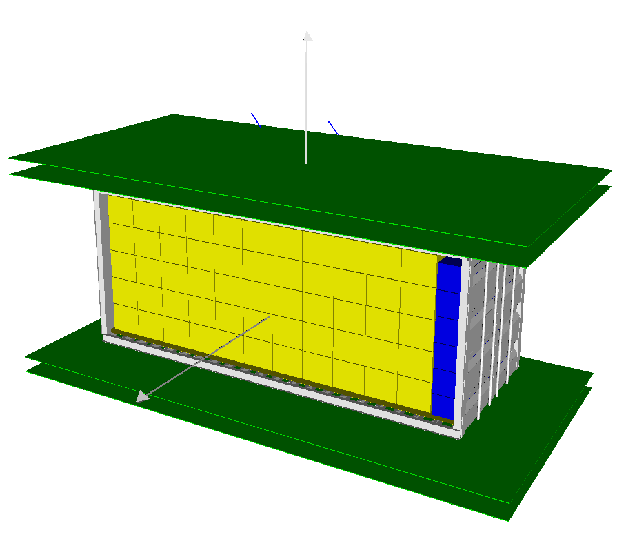

Figure 1(b) shows examples of scattering muon tracks and stopped muon tracks. On the left two scattered muons that went through the cargo are shown in blue color. The right particles (in red color) are stopped in cargo before reaching the lower tracker detectors.
2.1 Muon scattering tomography
Cosmic ray muon undergoes multiple coulomb scattering while passing through material. The angular distribution of scattered muon of momentum p is approximately Gaussian, with zero mean and standard deviation given by:
| (2.1) |
where is the ratio between velocity of muon V to velocity of light c, X0 is the radiation length of the material, L is the length of the material traversed. X0 is a material property and depends on the density of the material , the atomic mass A and the atomic number Z and can be expressed as[19]:
| (2.2) |
For material discrimination purposes in muon tomography we define the scattering density (), derived from Rossi formula [20]:
| (2.3) |
where is a nominal muon momentum and is with units in milliradians2/cm. The approximation c 1 for muons is used in this equation. The scattering density of a material represents the mean square scattering angle of muons passing through a unit depth of that material. For generating tomographic image scattering angles are accumulated at different locations generating a 3D map of scattering densities.
From equations 2 and 3 one can seen that the width of scattering angle distribution inversely depends on the material radiation length which is dependent on the atomic number of the material and material density. For materials with higher atomic numbers Z (high-Z) muons will scatter with larger scattering angles. It is therefore possible to characterize the density profile of a large object by measuring muon directions before and after passing through the target object. If cargo is a composite material muon scattering depend on its chemical composition. The combined radiation length of the composite material is given by formula [21]:
| (2.4) |
where W0 is the total mass of the sample in g. X0 is the combined radiation length of the sample in gcm-2. Wi is the mass of the individual component in g. Xi is the radiation length of the individual component gcm-2.
2.2 Absorption muon tomography
While passing cargo muons loosing their energy due to ionization and have a probability to be stopped and decay. The attenuation length depends on the density of the matter traversed. A muon before being stopped, will be able to cross on average a certain opacity X defined as X = dL, where is the density of the material and L is the particle path length. In the absorption tomography approach, tracks of muon, that were stopped in cargo can be reconstructed using algorithm described in publication [22]. This algorithm analyzes muon tracks, that were passed upper detectors but were not detected in lower detectors but lies on Line-of-Response (LOR), which connecting upper and lower detectors. Applying a muon absorption algorithm allows for the identification and counting of muons that have been stopped within the cargo. Since muon absorption depends on the cargo’s effective atomic number and density, this algorithm allow identify cargo material.
Following approach, developed in publication [23] we introduce a parameter, describing muon absorption as the “stopping power” () of a cargo material, which is given by the expression
| (2.5) |
where is the average momentum of the incident cosmic rays, Nscat the total number of scattering tracks, Nabs total number of tracks, which had been absorbed (or deflected) in the shipping container tracks, is a thickness of cargo material, – cargo volume, – scanning time. For each material the total number of scattered tracks Nscat and the number of absorbed tracks Nabs in the shipping container and cargo was calculated. The ratio of stopping power to scattering, while the latter expressed in following way
| (2.6) |
where is an average scattering angle of material.
3 Monte Carlo simulations
The geometry of a muon tomography station (MST) is shown in figure 1a. MST is consisting of two muon tracking modules above and below of the shipping container. Each tracking module includes two position-sensitive detectors, modeled as a plane made of plastic scintillator with a detection efficiency of 100% and dimension of 8 m 4 m 1 mm, covering a shipping container. The distance between two position-sensitive detector planes is 10 cm and distance between upper and lower modules is 3 m. The simulation of CRT and cargo in sea container is based on GEANT4 toolkit [4]. For generation of cosmic ray muons at sea level we use the Cosmic-Ray Shower Library (CRY) [24]. The origin points of generated muons were sampled from a horizontal plane surface of 10 m 10 m. Generated muons are interfaced with GEANT4 to simulate the interaction of muons with the detector, shipping container and cargo. The simulated data samples were produced by generating 5000 datasets for each material. Datasets were simulated by tracking 100000 muons, that corresponds to scanning time of 10 seconds. We use the standard physics list for high-energy particle transport named "FTFP_BERT". Synthetic datasets were analyzed using ROOT data analysis package [25]. The prototype of tracking detector based on multilayer array of plastic scintillating fibers readout with Silicon Photomultipliers (SiPMs) was constructed and tested [26]. The obtained spatial resolution in experimental runs was 120 microns (WFHM). To mimic the material discrimination accuracy of detectors with different spatial resolutions, the hit positions of muons produced in the detector plates were smeared using a Gaussian function with FWHM values of 0.235 mm, 1.17 mm, and 2.35 mm.
Contraband materials can be disguised as legal materials in customs declarations to evade detection. Muon Scattering Tomography (MST) can verify the real density and atomic number of the material in the container, discriminate between different products, and allow customs officials to compare the actual contents of a shipping container with what is declared in the customs documentation. According to research [27], the mean cargo density is just under 0.2 g/cm3. As a source of data for the selection of simulation scenarios one can use a PIERS (Port Import/Export Reporting Service) United States import data set. The sheer volume and complexity of the flow of commercial goods make it impractical to model every possible smuggling scenario. In this work, we have simulated scenarios of uniform cargo loading, which are most commonly used in international trade traffic. For the simulations we considered cargo materials in bulk form. The bulk density of a material is a combination of the density of solid particles, which includes occluded air, the density of the solids themselves, and the interstitial air. Data on the density of bulk materials we used in simulations were taken from Web Tech AutoWeigh Material Bulk Density Chart [28, 29].
| Bulk material | Bulk density (g/cm3) | Bulk material | Bulk density (g/cm3) |
|---|---|---|---|
| Paper (towel rolls) | 0.120 | Sugar | 0.800 |
| Tobacco (cigarette) | 0.190 | Dry pasta | 0.950 |
| Coffee (Roasted (Beans)) | 0.368 | Graphite (granules) | 0.720 |
| Tea | 0.433 | Marble (granular) | 1.089 |
| Polyethylene (Pellets) | 0.561 | Cement | 1.362 |
| Rice | 0.71 | Copper (Fines) | 1.618 |
4 Image reconstruction
Scattering muon tomography is based on the measurement of muon deflections when passing through the cargo. We calculate deflection using reconstruction algorithm based on the Point of Closest Approach (PoCA) method [30] which calculates the closest point of approach between two 3D lines. The PoCA algorithm makes the simplified assumption that the muon scattering occurs in a single-point and searches for the point of closest approach between the incident and outgoing reconstructed muon track directions. The shortest line segment between the incident and outgoing tracks is estimated by finding the pair of points of closest approach between the tracks. Midpoint of this line segment is considered as a scattering center of the muon. The scattering angle between the two tracks is calculated with the formula [19]:
| (4.1) |
Degree of muon deflection while passing the cargo in shipping container depend on material density and its chemical composition, thus an amount of reconstructed scattering centers using the PoCA approximation can be used for the material identified.


5 Results
The simulation of muon passage through MTS and cargo enables the production of data sets for statistical analysis. Hits on detector planes are recorded for each event, enabling the reconstruction of muon tracks using a ROOT analysis code. Four hits detected in upper and lower trackers, as shown on figure 1(a) allow calculate scattering angle and scattering center position using PoCA algorithm. If two hits are detected in upper trackers and LoR is passing the cargo than trajectory of stopped muon is calculated.
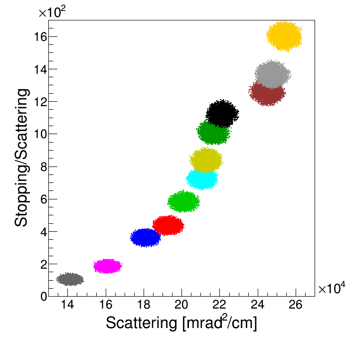
For the calculation of scattering density and stopping power, cargo dimensions are determined from the reconstructed tomographic image. In the 1D projections of the reconstructed tomographic image obtained from a 10-second scan, the edges of the cargo object can be identified using a ROOT script that calculates the first derivative, as described in publication [17]. In figure 2, tobacco packed into cardboard boxes forms an approximately cubic shape with dimensions 3 m 1.15 m 1.15 m. The detected cargo edges are found at positions -147.5 cm and 142.5 cm, while the actual positions are -150 cm and 150 cm. Simulated cargo materials were represented by a 5.852.302.30 m3 rectangular volume, almost fully filling the shipping container. In the simulation run, the calculated scattering density and scattering-to-stopping ratio are recorded. For each cargo material, 5,000 datasets were simulated. As shown in figure 3(c), the two-dimensional histogram of scattering and scattering-to-stopping ratio density distributions for different materials are well separated in 2D space and localized in distinct regions, demonstrating the material discrimination ability. The data show different behaviors in three regions. For organic materials up to tea, there is minimal scattering-to-stopping ratio variation but a stronger scattering density variation. Other organic materials—such as polyethylene (pellets), rice, sugar, and dry pasta—show a larger variation in scattering-to-stopping ratio than in scattering rate. Inorganic materials demonstrate a greater variation in scattering-to-stopping ratio, with scattering density changing minimally. The impact of chemical composition is visibly distinct.

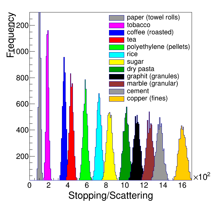
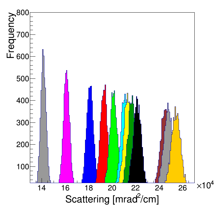
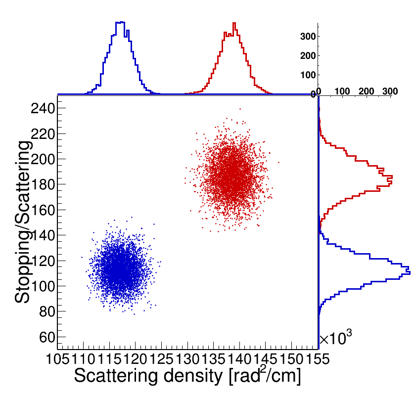
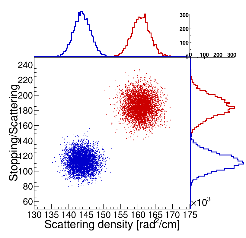
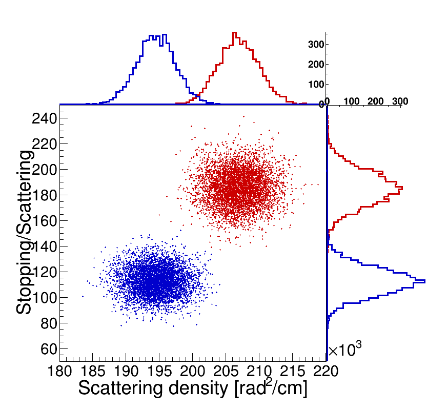
To numerically quantify the accuracy of material discrimination, we considered a scenario involving the smuggling of tobacco (cigarettes) declared as paper towel rolls. We simulated datasets for container fully loaded with 5 million cigarettes and container fully loaded with paper towel rolls. In figure 4 the scatter plot of scattering density versus scattering-to-stopping ratio are shown for paper towel rolls and tobacco for detector spatial resolutions of 0.235 mm, 1.17 mm, and 2.35 mm (FWHM). Colors indicate group membership of distributions. Colors indicate group membership of distributions. On the top of each 2D histogram in figure 4 we show the 1D histograms of scattering data, while on the right side we show the histogram of scattering-to-stopping ratio data. Compared to the scatter versus scattering-to-stopping ratio 2D map, the 1D distributions are limited due to the partial overlap of distributions for paper towel rolls and tobacco, making materials discrimination less distinctive. This demonstrates the superiority of 2D data analysis over 1D data analysis. These plots demonstrate the impact of detector position resolution on material discrimination analysis. As can be seen, there is expected degradation of discrimination of accuracy at worse spatial resolution.
For quantitative analysis of discrimination accuracy, we applied the Gaussian Mixture Model (GMM) algorithm, which helps categorize data into groups based on their probability distributions.


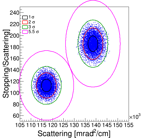
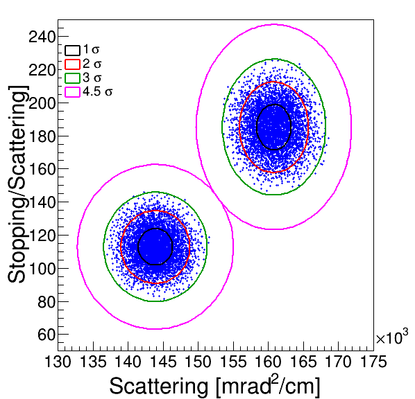
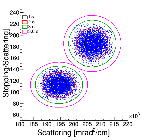
We initialize a 2D Gaussian GMM with two components and fit it to the data on the scatter plot (see figure 5). The confidence ellipses for each distribution are set to show 1, 2, 3 CL and confidence ellipse at which distributions are discriminated. As can be seen, the scattering versus scattering-to-stopping ratio distributions for towel paper and tobacco are accurately discriminated with more than 4 confidence level (CL) for the detector spatial resolution of 0.235 mm, 1.17 mm. For the spatial resolution of 2.35 mm (FWHM) discrimination accuracy is 3.5 CL.
6 Conclusions
In this work, we used Monte Carlo simulations based on the GEANT4 package to investigate the ability of cosmic ray muon tomography to perform prompt characterization of shipping container contents and verification of customs declarations. We developed a method of combined scattering and scattering-to-stopping ratio data analysis to improve the material discrimination ability of cosmic ray muon tomography. This method was applied to analyze simulated datasets for several cargo materials. We demonstrate how integrating scattering and scattering-to-stopping ratio data into a two-dimensional representation enables clearer differentiation between material classifications. The developed approach leverages the combined information from both types of data to enhance the accuracy of material discrimination in muon tomography applications, providing a powerful tool for detecting smuggled goods disguised as other items. For the specific case of tobacco smuggling, the combined analysis of scatter-absorption data allows for the accurate discrimination between tobacco and paper towel rolls with 5.5 accuracy for detector spatial resolution (FWHM) of 0.235 mm, 4.5 for 1.175 mm resolution (FWHM), and 3.5 which corresponds to 99.95% discrimination accuracy for 2.35 mm spatial resolution (FWHM) within a 10-second scanning time.
The ability to rapidly characterize cargo materials comes from the analysis of muon scattering and absorption data for large amounts of cargo material weighing several tons, resulting in high statistical precision. Thanks to the muon penetration power and the developed method of scatter-absorption combined analysis, cosmic-ray muon tomography can be an effective solution for non-invasive cargo inspections, aiding in the fight against contraband trafficking.
7 Acknowledgments
This work was partially funded by the EU Horizon 2020 Research and Innovation Programme under grant agreement no. 101021812 (“SilentBorder”).
References
- [1] L. Bonechi, R. D’Alessandro and A. Giammanco, Atmospheric muons as an imaging tool, Reviews in Physics 5 (2020) 100038.
- [2] S. Barnes et al., Cosmic-ray tomography for border security, Instruments 7 (2023) 13.
- [3] K.N. Borozdin et al., Radiographic imaging with cosmic-ray muons, Nature 422 (2003) 277.
- [4] L. Cuéllar et al., Soft cosmic ray tomography for detection of explosives, in 2009 IEEE Nuclear Science Symposium Conference Record (NSS/MIC), pp. 968–970, 2009, DOI.
- [5] Z. Yifan, Z. Zhi, Z. Ming, W. Xuewu and Z. Ziran, Discrimination of drugs and explosives in cargo inspections by applying machine learning in muon tomography, High Power Laser and Particle Beams 30 (2018) 086002.
- [6] J. Chen et al., Towards a muon scattering tomography system for both low-Z and high-Z materials, Journal of Instrumentation 18 (2023) P08008.
- [7] L.J. Schultz, Cosmic ray muon radiography, Portland State University (2003).
- [8] E. Åström, G. Bonomi, I. Calliari, P. Calvini, P. Checchia, A. Donzella et al., Precision measurements of linear scattering density using muon tomography, Journal of Instrumentation 11 (2016) P07010.
- [9] P. Checchia, Review of possible applications of cosmic muon tomography, Journal of Instrumentation 11 (2016) C12072.
- [10] V. Antonuccio, M. Bandieramonte, U. Becciani, D. Bonanno, G. Bonanno, D. Bongiovanni et al., The muon portal project: Design and construction of a scanning portal based on muon tomography, Nuclear Instruments and Methods in Physics Research Section A: Accelerators, Spectrometers, Detectors and Associated Equipment 845 (2017) 322.
- [11] C. Pugliatti, V. Antonuccio, M. Bandieramonte, U. Becciani, F. Belluomo, M. Belluso et al., Design of a muonic tomographic detector to scan travelling containers, Journal of Instrumentation 9 (2014) C05029.
- [12] C. Morris, J. Bacon, K. Borozdin, H. Miyadera, J. Perry, E. Rose et al., A new method for imaging nuclear threats using cosmic ray muons, AIP Advances 3 (2013) .
- [13] E. Preziosi, F. Arcieri, A. Caltabiano, P. Camarri, S. Casagrande, D. Cavicchioni et al., Tecnomuse: a novel, rpc-based, muon tomography scanner for the control of container terminals, Journal of Physics: Conference Series 1548 (2020) 012021.
- [14] A.S. Georgadze and V.A. Kudryavtsev, Geant4 simulation study of low-Z material detection using muon tomography, Journal of Instrumentation 18 (2023) C12014.
- [15] A. Georgadze, A. Giammanco, V. Kudryavtsev, M. Lagrange and C. Turkoglu, A simulation of a cosmic ray tomography scanner for trucks and shipping containers, Journal of Advanced Instrumentation in Science (2024) .
- [16] A.S. Georgadze, Simulation study into the detection of low- and high-Z materials in cargo containers using cosmic ray muons, Acta Physica Polonica B Proceedings Supplement 17 (2024) 1.
- [17] A.S. Georgadze, Automated object detection for muon tomography data analysis, Journal of Instrumentation 19 (2024) C07004.
- [18] Particle Data Group collaboration, Review of particle physics, Phys. Rev. D 98 (2018) 030001.
- [19] G.R. Lynch and O.I. Dahl, Approximations to multiple coulomb scattering, Nuclear Instruments and Methods in Physics Research Section B: Beam Interactions with Materials and Atoms 58 (1991) 6.
- [20] V.L. Highland, Some practical remarks on multiple scattering, Nuclear Instruments and Methods 129 (1975) 497.
- [21] ATLAS Collaboration, Calculation of radiation length in materials, PH-EP-Tech-Note-2010-013 (2010) .
- [22] S. Vanini, P. Calvini, P. Checchia, A. Rigoni Garola, J. Klinger, G. Zumerle et al., Muography of different structures using muon scattering and absorption algorithms, Philosophical Transactions of the Royal Society A 377 (2019) 20180051.
- [23] G. Blanpied, S. Kumar, D. Dorroh, C. Morgan, I. Blanpied, M. Sossong et al., Material discrimination using scattering and stopping of cosmic ray muons and electrons: Differentiating heavier from lighter metals as well as low-atomic weight materials, Nuclear Instruments and Methods in Physics Research Section A: Accelerators, Spectrometers, Detectors and Associated Equipment 784 (2015) 352.
- [24] C. Hagmann, D. Lange and D. Wright, Cosmic-ray shower generator (CRY) for monte carlo transport codes, in 2007 IEEE Nuclear Science Symposium Conference Record, vol. 2, pp. 1143–1146, 2007, DOI.
- [25] R. Brun and F. Rademakers, Root — an object oriented data analysis framework, Nuclear Instruments and Methods in Physics Research Section A: Accelerators, Spectrometers, Detectors and Associated Equipment 389 (1997) 81.
- [26] G. Anbarjafari et al., Atmospheric ray tomography for low-Z materials: implementing new methods on a proof-of-concept tomograph, arXiv preprint arXiv:2102.12542 (2021) .
- [27] M. Descalle, D. Manatt and D. Slaughter, Analysis of recent manifests for goods imported through US ports, Tech. Rep. Lawrence Livermore National Lab.(LLNL), Livermore, CA (United States) (2006), DOI.
- [28] W.T. AutoWeigh, Material Bulk Density Chart material bulk density chart, 2024.
- [29] Bulk-density-guide, Bulk-density-guide, 2020.
- [30] R. Hoch, D. Mitra, K. Gnanvo and M. Hohlmann, Muon tomography algorithms for nuclear threat detection, Opportunities and challenges for next-generation applied intelligence (2009) 225.