Enhanced Runge-Kutta Discontinuous Galerkin Method for Ultrasound Propagation in Transit-Time Flow Meters
Abstract
We illustrate a time and memory efficient application of Runge-Kutta discontinuous Galerkin (RKDG) methods for the simulation of the ultrasounds advection in moving fluids. In particular, this study addresses to the analysis of transit-time ultrasonic meters which rely on the propagation of acoustic waves to measure fluids flow rate. Accurate and efficient simulations of the physics related to the transport of ultrasounds are therefore crucial for studying and enhancing these devices. Starting from the description of the linearized Euler equations (LEE) model and presenting the general theory of explicit-time DG methods for hyperbolic systems, we then motivate the use of a spectral basis and introduce a novel high-accuracy method for the imposition of absorbing and resistive walls which analyses the incident wave direction across the boundary surface. The proposed implementation is both accurate and efficient, making it suitable for industrial applications of acoustic wave propagation.
keywords:
Runge-Kutta discontinuous Galerkin methods , linearized Euler equations , ultrasonic flow meters , hyperbolic PDEs , acoustic impedance , absorbing layers1 Introduction
High-accuracy simulations have increasingly become essential in many science fields such as fluid dynamics [6, 46], electromagnetism [21], electrophysiology [7, 14] and acoustics [29]. The flow metering industry has followed this trend and several investigations have been performed aiming at improving and optimizing measurement performances [33, 40, 39]. In particular, transit-time ultrasonic flow meters rely on the propagation of ultrasound waves and the computation of their transit time through the moving fluid to estimate the volumetric flow rate [5]. Hence, the analysis of the performance of such devices inherently includes the coupling between the acoustic waves dynamics and the underlying fluid flow.
Discontinuous Galerkin (DG) methods represent nowadays a noteworthy and widespread alternative to more classical continuous methods for the resolution of partial differential equations (PDEs). Originally proposed in the seventies for hyperbolic equations [38, 28] and few years later for second-order equations [3, 15], they were disregarded for a long time because of their higher costs due to the larger number of degrees of freedom. The success of these methods came only with their rediscovery in the nineties thanks to a more in-depth analysis of their properties for conservation [12, 11] and diffusion problems [13, 35]. DG methods have indeed proven to be well-suited for polynomial and grid adaptivity [9] which also allows for highly accurate solutions in many different fields such as the ones stated above [44, 22, 34]. Moreover, the decoupling of the adjacent elements facilitates fast parallel computations and leads to some powerful algebraic properties like the efficient inversion of the mass matrix [20, 10].
In this work, we study and develop a DG formulation for ultrasound propagation in a background water flow aiming at simulating the real pressure wave dynamics inside ultrasonic flow meters. While the adoption of discontinuous methods for similar purposes has already been explored in some previous works [30, 31, 24], in the present research we introduce the Dubiner-Koornwinder spectral basis [26, 16] and a novel imposition of realistic boundary conditions to improve accuracy and efficiency of the computation but also providing a better representation of the physical phenomena involved. Furthermore, we test the method on a realistic three-dimensional flow metering setting.
In Section 2 we describe the PDE model in terms of the linearized Euler equations for the ultrasound propagation in a moving medium, followed by its space discretization through the discontinuous Galerkin formulation and the time integration using the fourth-order Runge-Kutta scheme. Then, we dedicate Section 3 for a discussion about suitable boundary conditions and we propose a novel strategy for imposing absorbing and resistive walls. To conclude, in Section 4 the accuracy and good behaviour of the proposed methods are assessed through different tests.
2 Discontinuous Galerkin formulation
The linearized Euler equations (LEE) represent one of the most popular models to describe the propagation of sound waves in a fluid [4, 41]. Moreover, their use for ultrasonic water meters applications is already shown in [31]. The model is obtained from the compressible Euler equations decomposing the flow variables into the background flow contribution and the perturbation components caused by the ultrasounds propagation. Since the speed of sound is usually much higher than the fluid motion, it is acceptable to consider a stationary background flow as assumed in the LEE model. Moreover, the use of the inviscid Euler equations is motivated by the low viscosity of the ultrasound waves. Finally, we assume the thermodynamic process to be isentropic, an hypothesis that is often made in acoustics [32].
2.1 Analytical model for ultrasound propagation
Let , where we consider either or dimensions, and let be the constant speed of sound in the fluid. We define as the stationary background density, pressure and flow in respectively. For simplicity, we assume the fluid to be homogeneous and so to be constant. Equivalently, let be the perturbation flow components which are instead time-dependent.
The linearized Euler equations are therefore:
| (1) |
where is the final time and the energy conservation equation derives from the isentropic assumption.
The LEE model is hence a hyperbolic system of equations or if one writes the system only in terms of by removing .
In contrast with more classical boundary conditions for hyperbolic systems, we opt for the imposition of the boundary flux on the entire border , where is the outward normal vector with respect to the boundary surface while no condition is imposed for . This choice has been recently proven to be well-posed [23], and is often adopted in acoustics since it allows to describe conditions that occur in real problems. More details related to the definition of for the application to realistic simulations will be provided in Section 3.
It is convenient to explicitly suppress the pressure and write Equation (1) in divergence form:
| (2) |
where the second equation holds for and is the -th standard unitary vector in .
The divergence form is now more suitable for the definition of the weak formulation. Multiplying the equations with the test functions , integrating on the domain and performing integration-by-parts, we obtain
| (3) |
for the density equation and
| (4) |
for the momentum equations. We notice again that Equation (4) holds for each and it should not be interpreted as the Einstein notation. Moreover, we note that the assigned boundary flux is weakly imposed in the fourth integral of Equation (3). The weak imposition of boundary conditions is a well-known strategy and often necessary in the DG framework. We refer the reader to [42] for the motivation and application of weak boundary conditions to the wave equations.
2.2 DG space discretization
To formally obtain a discretization in space, Equation (3) and (4) from the original space are restricted to the discretized space defined as
| (5) |
where is a conforming triangulation of the domain , indicates the averaged grid size, is the restriction operator to the element and is the space of polynomials of order at most . Differently from common FEM spaces, functions in are in general discontinuous on the edges between adjacent elements but are necessarily continuous inside each element. As already mentioned, this disconnection allows interesting properties, for instance the -adaptivity where can be chosen differently in each element. On the other hand, DG formulations require the definition of an artificial/numerical flux to be evaluated on the internal edges in order to let the information be shared between the discontinuous elements. We introduce and opt for the Lax-Friedrichs numerical flux which is generally known to be a simple, effective and widespread choice.
Definition 2.1 (Discontinuous mean and jump [20]).
Let be an oriented internal edge with normal vector . Let be the two elements that share and where is chosen as outward with respect to . If are the associated evaluations of a discontinous function , we define
as the discontinuous mean operator and
the discontinuous jump operator evaluted on .
Definition 2.2 (Lax-Friedrichs numerical flux [20]).
Let and suppose to solve the following general hyperbolic system
where is the flux. The Lax-Friedrichs numerical flux evaluated on an oriented internal edge with normal vector is defined as
| (6) |
where
For multidimensional systems as Equation (1) where and , the same can be generalized through the column-wise application of the scalar product and mean operator.
In our case, we can infer from Equation (2) that for is the linear operator defined through the matrices
The Lax-Friedrichs flux is often used because of its simplicity, efficiency and good convergence properties [20, 8]. While the central flux defined using only the first term in Equation (6) is of common usage, it guarantees convergence only in and not in [8]. In practice, this implies that the numerical solution could be quantitatively similar to the exact solution but might have poor regularity.
With few calculations, an explicit value for can be obtained and the value is approximately if (which corresponds to the reasonable hypothesis of subsonic water flow). This is coherent with the physical interpretation of that is exactly the maximum speed of the wave.
Let be the set of all the oriented internal edges with associated normal , the DG problem can then be stated: for every , find and such that
| (7) |
and
| (8) |
for every , and .
Following the classical DG theory, volume integrals are performed element-wise so that the arguments are continuous and integrable disregarding the internal jumps. Notice that the integration of the numerical flux yields no ambiguity in the evaluations of the discontinuous functions on the edges. Moreover, the integrals on the boundary evaluate the functions on the internal border side.
Let be a set of basis functions for where is the dimension of the discretized space. The explicit definition of such basis is postponed to Section 2.4 as well as the quadrature formulae that are used to compute the integrals in Equation (7) and (8). Furthermore, let be the vector containing the Fourier coefficients of the flow unknowns with respect to . It is therefore convenient to create copies of the basis functions which we define as . Equation (7) and (8) can then be rewritten in the following compact algebraic form, that will be useful for the upcoming sections:
| (9) |
where is the mass matrix and is the matrix associated with all the remaining terms in Equation (7) and (8). These terms are indeed linear with respect to and the dependence on is due to the imposition of the boundary flux . It is common to store only the local mass matrix applied to the reference element since it can be quickly reconstructed for each affinely mapped element. On the contrary, this strategy is evidently not applicable to the matrix except for constant background flows. A low-storage method is still possible by assembling each local at every time step but this approach significantly undermines the efficiency of the scheme. In conclusion, a global assembly is still considered due to its considerable performance despite the burden in terms of memory.
2.3 Efficient explicit-time discretization
In this section the original problem in Equation (1) is fully discretized with a explicit-time numerical integration. Let us introduce the partitioning of the time interval as where is the uniform difference between two consecutive time steps and is the total number of time steps. Moreover, let be the numerical evaluation of the solution vector at the -th time step, where . is inherently the projection on of the problem initial condition.
We require an accurate and stable time discretization method that allows to efficiently perform ultrasound simulations with thousands of time steps. Runge-Kutta discontinuous Galerkin (RKDG) methods have been consolidated as a class of powerful methods for the full discretization of convection-dominated problems. Proposed and studied in a series of works [12, 11], they have been proven to be at the same time fast and accurate. Fourth-order Runge-Kutta (RK4) is hence chosen and its application to Equation (9) performs the following operations at each time step:
| (10) |
In Equation (10), the vectors have the role of intermediate step solutions and allow for the fourth-order accuracy. Many different alternatives to RK4 are possible, for instance the choice of a different order or the adoption of Strong-Stability-Preserving (SSP) Runge-Kutta methods [27, 18]. However, due to the linearity of the LEE model in Equation (1) and the accuracy order that is usually desired for such simulations, RK4 turns out to be a good compromise of accuracy and simplicity.
Stability is achieved by satisfying the well-known Courant-Friedrichs-Lewy (CFL) condition
where is a characteristic parameter of the adopted RKDG scheme and is the maximum wave speed. The latter can be computed from the eigenvalues of the problem flux , thus it coincides with whose value is approximately when the background flow is subsonic, coherently with the physical intuition. In conclusion, given , must be large enough to satisfy the CFL condition with .
We remind that the time update of can be performed by updating only the surface integral associated to the boundary flux . Moreover, the mass matrix needs to be inverted only once and this can be achieved efficiently element-wise. Indeed, since each DG basis function has support in a single element, the mass matrix has an element-block structure. This, coupled with the performances of the RKDG method, leads to a very efficient time stepping strategy.
2.4 Spectral basis and quadrature formulae
While the above consideration hold for a wide class of DG methods (e.g., when adopting the nodal discontinuous Lagrangian basis), in this work we choose to adopt the modal Dubiner-Koornwinder basis [26, 16]. These spectral polynomials are constructed from a transformation that collapses quadrilaterals on simplices to obtain a -orthogonal basis on triangles and tetrahedra which is formed by generalized tensor products of Jacobi polynomials. Their explicit definitions are reported in A.
The basis orthogonality leads to a diagonal mass matrix which considerably reduces time and memory requirements. In particular, if is the number of degrees of freedom per element, the number of non-zero elements with nodal DG bases is only but it can be even reduced to ) with a diagonal mass matrix. This discrepancy also affects the performance during the pre-inversion of the matrix and numerous matrix-vector products. While the former operation is executed only once, mass matrix products are performed at each time step. Being in dimensions and in 3 dimensions, it is clear that substantial differences appear when performing high-order discretizations (or even only ). These expected performances improvement are verified in Section 4.2 where the ultrasounds propagation is simulated with order .
To conclude this section, a proper quadrature formula is defined for the integrals in the weak formulation of Equation (7) and (8) as well as for the computation of the Dubiner projection coefficients. The Gauss-Legendre quadrature nodes are known to work well with high-order discretizations using spectral bases and they represent therefore the reference choice in one dimension [20]. Different possible options are available to extend in 2 and 3 dimensions and we opted for the so-called symmetrical Gauss formulae, proposed by [47] and provided by the XLiFE++ library [25]. We note that internal quadrature formulae are preferred because they allow to avoid some complications due to the singularities of the Dubiner functions on the borders.
3 Application of acoustic impedance for absorbing and resistive boundaries
As stated in Section 2, our boundary conditions prescribe the assignment of the boundary flux on the entire boundary. While perfectly reflecting walls and symmetry planes can be achieved by simply assigning , the simulation of absorbing layers (i.e., walls that capture incoming waves without reflections) is more complicated, especially in higher spatial dimensions. We note that absorbing layers are crucial when the real domain is infinite or very large and simulations are instead performed in a smaller region as a finite section in an ultrasonic flow meter pipe. For such reasons, different methods have been proposed in literature as the so-called perfectly matched layers (PML) where the wave decays following a reaction-diffusion model in an external and artificial region. However, PMLs have been proven as not always accurate (e.g., in [37]) and require an additional cost for the problem resolution in an extra domain. What we propose here is a novel, truthful and realistic method that is based on the imposition of the acoustic impedance. The following definitions are readapted from [36, Section 6.3].
Definition 3.1 (Acoustic impedance of a surface).
Let an acoustic wave be represented in the complex exponential formalism (). We define the acoustic impedance with respect to a surface as the ratio
where is the normal vector to the surface that is outward with respect to the incoming wave.
Proposition 3.1 (Acoustic impedance on the interface between two homogeneous mediums).
Let and be the density and speed of sound in two mediums. Assume the width of the second medium to be infinite. The impedance on the interface with respect to the waves coming from the first medium is
where is the penetration angle that can be obtained from the incidence angle using the acoustic Snell’s law:
From Proposition 3.1 we therefore find a proper boundary flux imposition for different wall materials. If the wall is assumed to be thick and rigid enough, which is needed in practice to neglect resonance effects ([2, Chapter 11]), we have a condition of realistic/dissipative wall. With few calculations, the boundary flux can be written as
| (11) |
where is the angle of incidence of the sound wave. Note that the argument of the square root is zero when the critical angle of the Snell’s law is achieved. When this happens, the impedance wall behaves as a perfectly reflecting wall (i.e., or equivalently ).
The condition for an absorbing layer can be obtained as a specific case of Equation (11), i.e., when the wall material is the same as the conductive medium. The absorbing condition will therefore read as
| (12) |
Some difficulties arise to determine or estimate the wave propagation angle . Indeed, it is well-known that imposing the impedance in dimensions can be considerably more complex and that most of the strategies proposed involve frequency domain analysis. In the presence of absorbing layers, we opt instead for a novel strategy that consists in the estimation of the angle of incidence directly from the incoming velocity field in the time domain. In an explicit setting as the RK discretization from Section 2.3, if is the direction coefficient, we propose the following algorithm:
| (13) |
Here, is a memory coefficient and takes the role of filtered velocity field on the border that can be initialized with a very small value (such as despite it depends on the problem under consideration). The filtering operation provides a stable value for the propagation direction also in proximity of the zeroes of the waves. The sign function is instead needed to ensure monotonicity to the filtering operation.
Equation (13) can be used in the absorbing impedance condition from Equation (12) while it is not meant to be used in the dissipative wall condition in Equation (11). In the latter case the sound reflection does not allow a simple formula for the estimate of the incoming wave direction. Although, other solutions are certainly possible when the ultrasound trajectory is already known or can be estimated. Under this hypothesis, the angle can be provided a priori and, as previously mentioned, dissipative walls can be imposed as perfectly reflecting for high angles of incidence.
4 Numerical results
This section is devoted to numerical tests assessing the behaviour and performance of the above proposed methods. The code has been implemented using FreeFem++ 4.12 [19] adding the Dubiner basis and high-order quadrature formulae as plugins. Moreover, the Message Passing Interface (MPI) has been adopted to parallelize the matrix assembly and the matrix-vector products through a domain decomposition method; details are provided in Section 4.5. In the following tests we always consider m/s as the speed of sound in water and kg/m3 as the density of water. All the calculations are performed on CPUs Intel Xeon E5-2699 v3 @ 2.30 GHz. Moreover, Gmsh 4.8 [17] is employed to generate the unstructured grid . We will associate the grid length with the parameter provided to the software that specifies the level of refinement on the boundary.
4.1 Convergence analysis
We consider a simple two-dimensional test where the exact analytical solution is known. Therefore, we can assess the convergence of the proposed methods and perform an accuracy comparison for different polynomial orders.
Let the background flow as well as the initial ultrasound flow be at rest ( and constant). This choice is motivated by the fact that the flow convection is very slow with respect to the wave dynamics and therefore it can be correctly simulated at any order. We define the domain as a square and the source inlet, to be applied only on the left edge, as
| (14) |
where Hz is the source frequency and is the indicator function. The exact solution of the horizontal velocity is therefore known to be
| (15) |
whereas the vertical velocity is uniformly zero. In addition, one can utilize Equation (1) to obtain the simple Cauchy problem
which, coupled with Equation (15), yields . We set a final time s and the largest time step such that the CFL condition for stability is achieved. It has been experimentally verified that this condition alone entails a negligible time discretization error with respect to the total error. Moreover, the CFL coefficient has been confirmed to follow a trend in accordance to the bound from [12].
Results are illustrated in Figure 1 where the standard error has been computed with respect to through single-core simulations. We remind that the error is defined as even if the first contribution is almost negligible due to the fast variation of the functions considered.
We observe that all the methods exhibit the correct convergence trend even if higher rates (i.e., for ) are not fully achieved. This is presumably due to the fact that the CFL condition is more strict for greater orders and many time steps lead to some dissipation from the Lax-Friedrichs flux. On the other hand, the plot on the right shows how low-order methods represent the worst trade-off between simulation time and accuracy while higher orders () still represent the best choice for high-fidelity simulations of ultrasounds.
4.2 Spectral basis performance
To assess the benefits from the choice of a spectral method (Section 2.4), we devote this section to a comparison between the Lagrangian and Dubiner bases in terms of memory and time costs.
We run in a single core the same test case as in Section 4.1 with and m. Results are shown in Table 1 where the nodal Lagrangian basis is defined as in [20].
Although the use of complex spectral functions entails a slightly longer time to assemble the DG matrices, this is minimal compared to the improvement in the inversion of the mass matrix and the total simulation time. As already mentioned in Section 2.4, the mass matrix using nodal DG bases is block diagonal where each block corresponds to an element. A naive inversion would lead to operations but it can be even decreased to by only inverting the local mass matrix associated to the reference element and scaling by the Jacobian of the affine map. Since the diagonal spectral matrix yields a inversion cost, the ratio between the values in the second line is as expected approximately in two dimensions. We remark again that spectral bases can be leveraged to improve the cost of the pre-inversion operation which, despite being performed only once, it could correspond to a substantial burden when the number of time steps is limited.
In addition, multiple matrix-vector products have to be performed at each time step using the inverse of the mass matrix. Therefore, a diagonal mass matrix speeds up the total simulation time and reduce the memory requirements. However, a comparison between the values in the two columns is in this case less explicable since these both include the considerable cost to save and perform operations with the operator .
| Lagrangian basis | Dubiner basis | |
| Matrices assembly time | 43.57 s | 46.59 s |
| Mass matrix inversion time | 30.18 s | 1.69 s |
| Simulation time* | 604 s | 495 s |
| RES memory | 1.31 GB | 0.84 GB |
| *execution of all the time steps after the assembly and inversion preprocessing phases. | ||
4.3 Totally absorbing wall tests
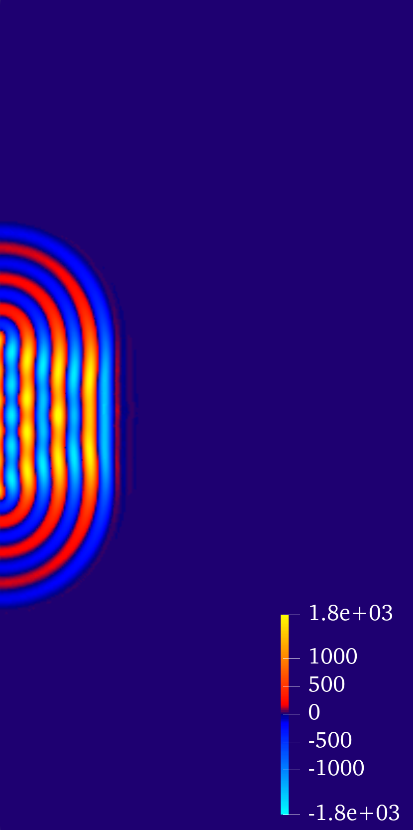
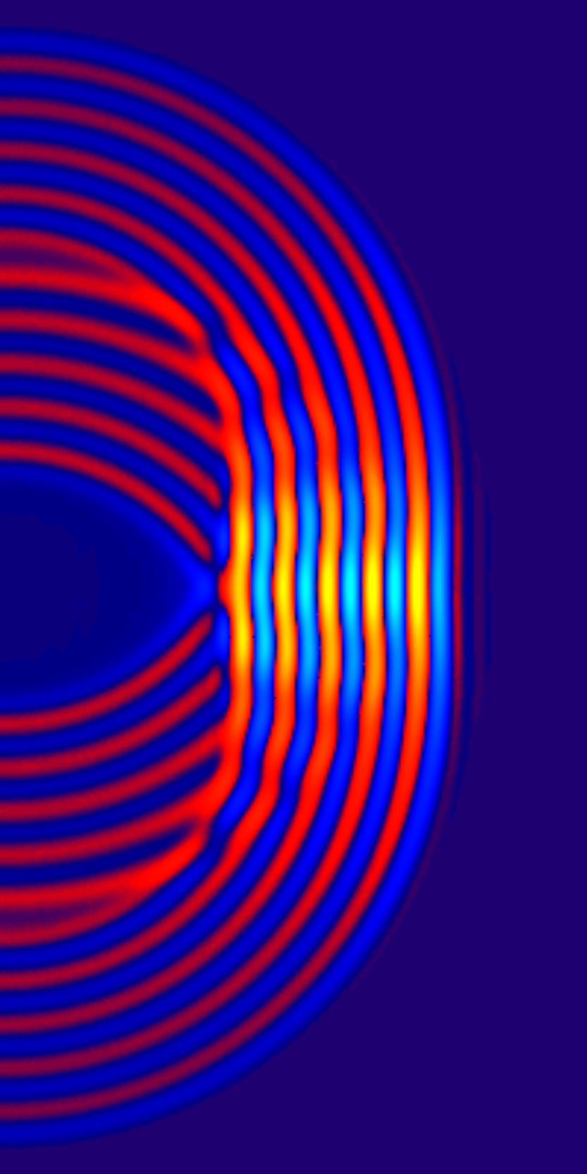


In this section, we test the efficacy of the proposed algorithm for the imposition of the absorbing layers (Equation (13)).
The domain is rectangular: while the background is defined as a standard pipe Poiseuille flow:
| (16) |

where m is the radius of the pipe, in this case half of the domain height, Pas is the dynamic viscosity of water, and is such that the velocity in the center of the domain is m/s. The value of the pressure offset is irrelevant since the LEE equations include only the derivatives of the background pressure and, thus, we can arbitrarily assign Pa.
Acoustic waves are generated at the left edge following the same profile as in Equation (14) but with support only in . To test the impedance condition, all the edges except the inlet are set as absorbing with . Motivated by the previous convergence tests, we choose s, , m and 2000 time steps.
Figure 2 depicts four snapshots of the simulation and qualitatively shows the well-behaviour of the absorbing imposition.
In order to quantify the perturbation due to the ultrasounds in the domain, we compute and display in Figure 3 the norm of the sound pressure at each time step. We observe that the perturbation starts from zero and reaches a constant value, that is kept from roughly s to s. In this time interval there is perfect conservation of the energy in the domain since there is no further source term and the absorbing walls have not been reached yet. The norm of the pressure starts to decrease when the waves hit the absorbing walls at around s. The steepest descent coincides with the absorption of the main horizontal component, while the pressure perturbation decreases more gradually when the waves are later absorbed in the other directions. In the final part we observe the quality of the proposed algorithm: while the orthogonality assumption (i.e., Equation (12) with ) effectively removes the main wave components, it is the correct estimate of the incident angles from Equation (13) that allows to remove the remaining energy from the domain.
4.4 A 2D clamp-on flow meter simulation
This test evaluates the proposed methods in a more practical context such as the measurement in a 2D clamp-on flow meter. While this setup is far from comparable to modern industrial flow meters, which have a high level of three-dimensional complexity, it represents a fair compromise to analyse the behaviour of the methods in a simple setting. Moreover, similar geometries have been previously adopted in other works such as [31].
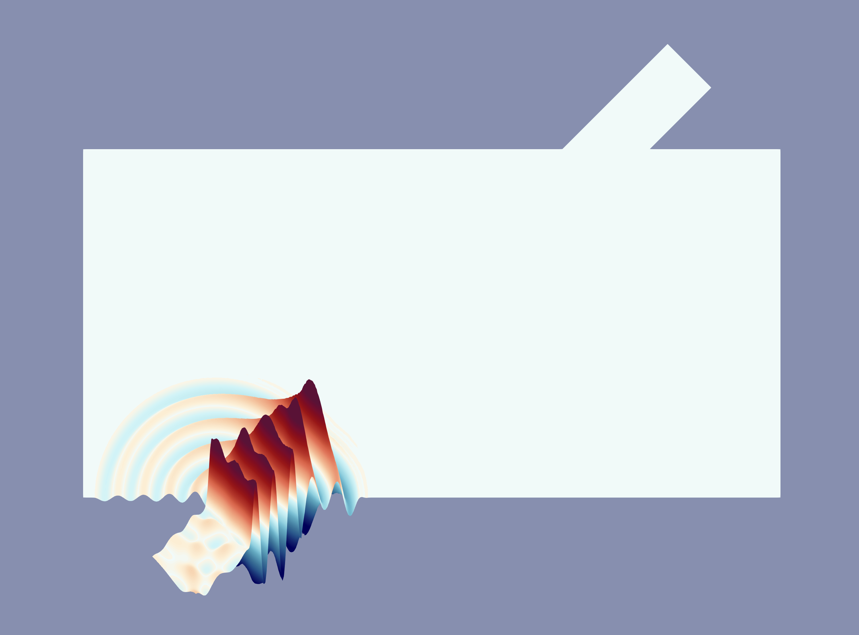
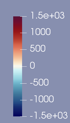
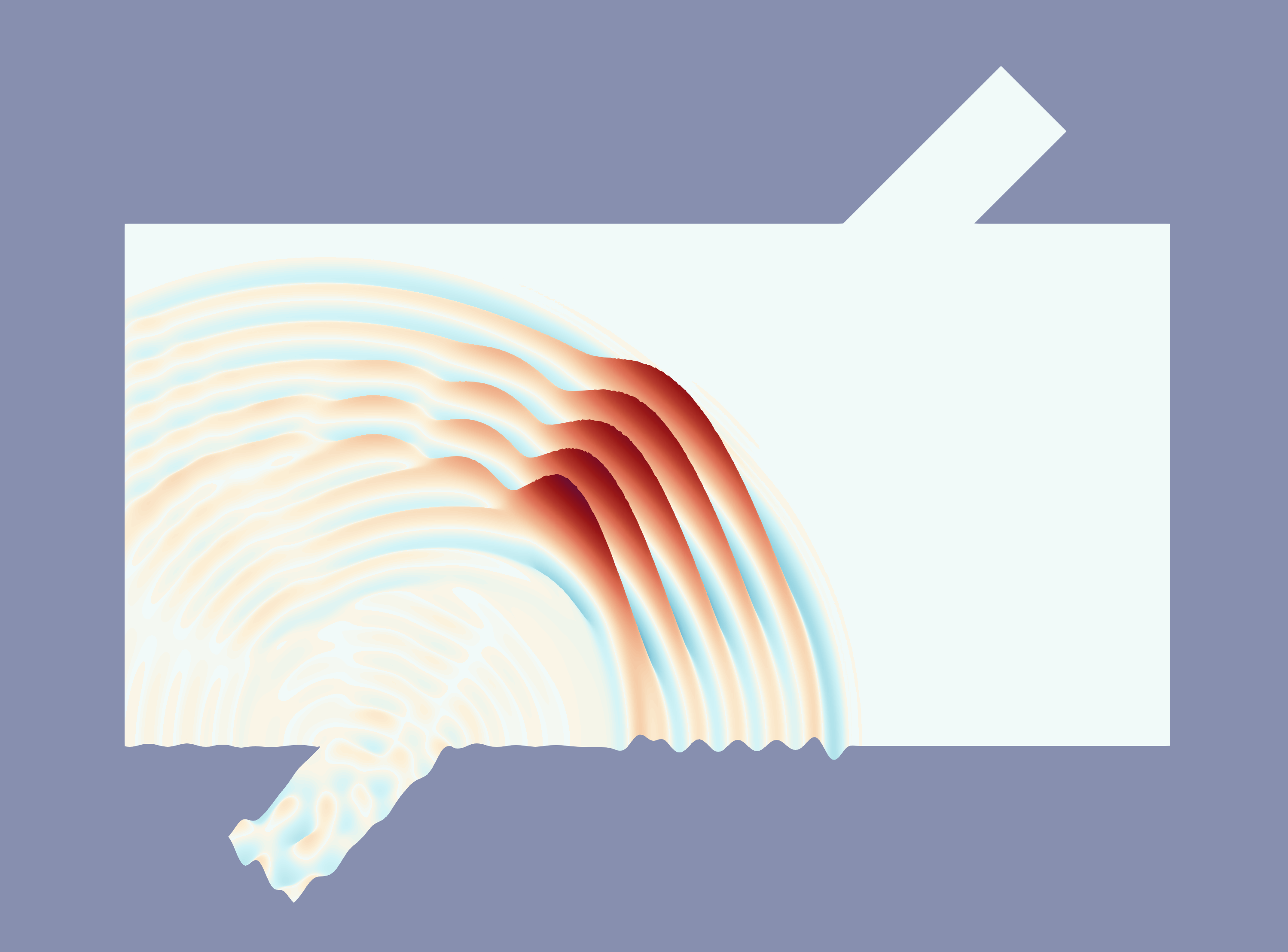
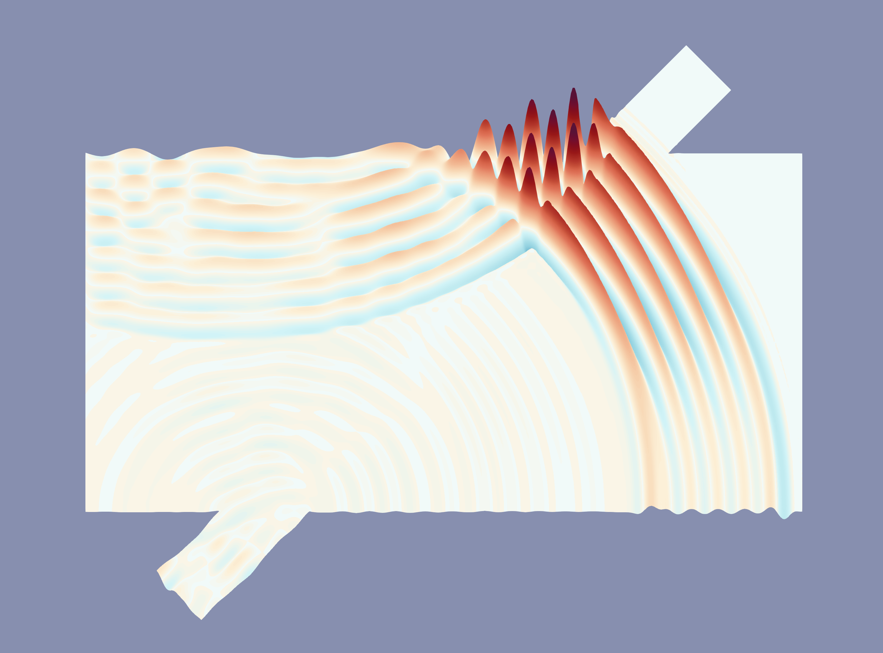
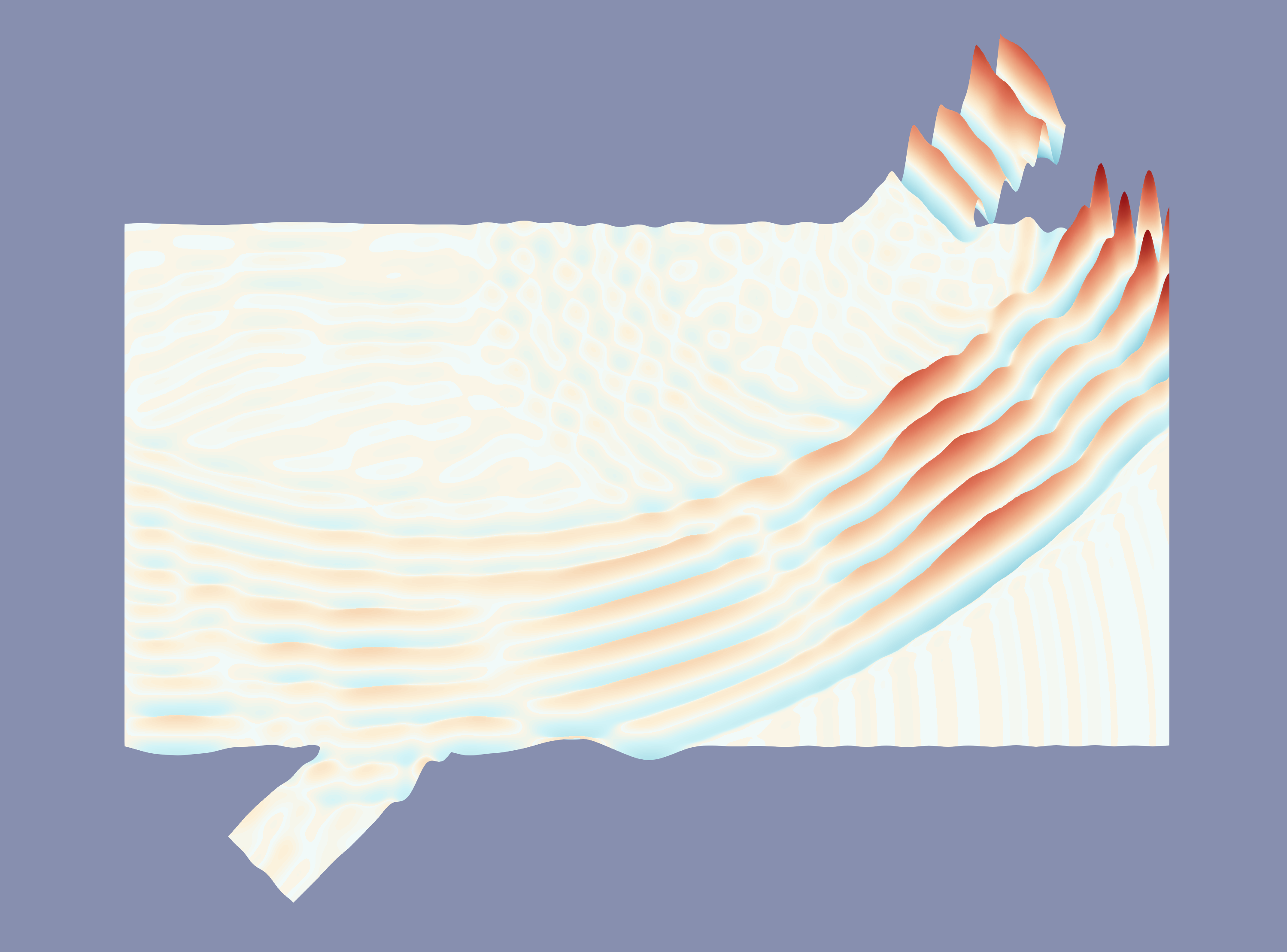
The simple clamp-on geometry is shown in Figure 4 where the horizontal and vertical lengths are respectively 0.04m and 0.02m. We choose s, , m and 3000 time steps. The same inlet profile from Equation (14) is applied at the bottom-left corner. Moreover, the same Poiseuille background flow from Equation (16) is used. We assign perfectly-reflecting walls on the entire boundary except for the absorbing layers on the vertical walls (that represent the flow inlet and outlet) with and the top-right corner which is imposed as a realistic/resistive wall with perpendicular incident angle. In particular, assuming the flow meter to be made of polyphenylene sulfide (PPS), we assign kg/m3 and m/s. The problem is hence solved non-dimensionally with respect to the SI system.
Qualitative snapshots are shown in Figure 4. The behaviour of the walls and absorbing layers are as expected. While not shown, the plots of the velocity and density perturbation have similar characteristics.
Besides these qualitative results, it is interesting to investigate the pressure measurements at the transducers. Trying to mimic the functioning of an ultrasonic transit-time flow meter, a second simulation is performed where the acoustic wave inlet and the resistive wall are switched. Therefore, we distinguish between forward (moving with the flow) and backward (moving against the flow) waves as well as bottom-left and top-right transducers. The measurements of both waves are then shown in Figure 5.


While at the sender the two pressure measurements are identical, the two waves presents a phase shift when they are measured on the receiving transducer because of the wave convection due to the water flow. The temporal difference between the wave peaks of the two signals is on average 18 time steps, i.e., s. Hence, we can use the classical formula for the estimation of the water velocity in transit-time flow-meters [5]
where is the difference in time between forward and backward waves and is the horizontal distance between sender and receiver. The obtained result is m/s that is indeed a precise estimate of the averaged horizontal background velocity m/s, where is the path from the sender to the receiver and its length.
4.5 Parallel calculations for the 3D flow meter simulation
Previous tests and simulations are performed only in two spatial dimensions and simple geometries. Therefore, this final section is dedicated to a qualitative assessment of the correct 3D extension of the previously proposed methods as well as the application to a more realistic case. Calculations are in this latter case more demanding and so we introduce a simple but powerful parallel scheme.
The most expensive operations at each time step are represented by the matrix assembly and the multiple matrix-vector products using . Indeed, no system resolution is performed thanks to the pre-inversion of the mass matrix and the cost to assembly the remaining terms (vectors and the diagonal mass matrix) is in comparison negligible. A very effective parallelization consists in the assembly of local sparse matrices, where is the rank number, each one referring to a subset of the entire domain yielding a domain decomposition method. To have more efficient calculations and no further memory occupied, it is preferred to have a non-overlapping partition where the shared interfaces have minimum length. The domain splitting algorithm has been implemented over FreeFem++ and is based on selecting vertical slices with regular horizontal length. This simple strategy is motivated by the horizontally extended geometry of the ultrasonic meters but there is certainly room for improvement. The local matrices are never assembled together, instead the matrix-vector product is performed with the local matrix and the global vector. Finally, an MPI_reduce operation allows to sum up all the local vector results in order to obtain the global product. This simple algorithm turns out to be very powerful since it almost-linearly reduces the costs related to the two mentioned expensive operations.
Adopting this strategy with cores, we perform a 3D simulation taking the geometry from [39], which is described as a suitable compromise between numerical applications and fidelity to the lowIQ 2200 meter from Kamstrup A/S. Different from the simpler clamp-on geometry in Section 4.4, the sender and receiver are placed on the upper border of the pipe while the correct trajectory is given from the double reflection on two wedges located on the bottom. To reduce the calculation effort, only one of the two halves of the pipe is used imposing a symmetry condition . Moreover, the two lateral faces are again imposed as absorbing with and the receiver is imposed as a PPS resistive wall with perpendicular incident angle. The wedges are instead imposed as perfectly reflecting since the angle is greater than the critical angle. The source profile is the same as in Equation (14), the background flow is given from the RANS solution in [39] and s with time steps. To obtain a high fidelity simulation, the mesh is composed by 248’646 tetrahedral elements, which correspond to the averaged grid size m, and the polynomial order is again . We notice that these choices lead to the significantly large value for each of the four variables. This can be considered as highly demanding for standard FEM schemes but the parallel RKDG method takes approximately 28 hours and the results are then shown in Figure 6. Thus, we can qualitatively confirm the capacity of the method to correctly simulate the entire trajectory of the ultrasound wave followed by its dissipation in a reasonable time frame.
5 Conclusions
In this work we have simulated the propagation of ultrasonic waves through the approximation of the linearized Euler equations by discontinuous Galerkin methods with the Dubiner spectral basis and a novel algorithm for the imposition of absorbing and resistive walls.
Several tests performed to assess this approach showed good convergence behaviour and the expected performance improvement due to the use of the spectral basis and a Runge-Kutta explicit-time formulation. Moreover, when combined with the proposed absorbing conditions, this method proves itself capable of accurately and efficiently simulating also more complex conditions like the sound wave propagation within an ultrasonic flow meter.
Hence, despite the simplicity of the proposed tests, we believe that such studies can be easily extended to more practical problems and that the industrial research community can exploit these advances in numerical methods for conservation laws to improve the precision of the modern flow metering instruments.
6 Data availability
Data and code are properties of Kamstrup A/S. They are available upon request under certain conditions.
Acknowledgments
The authors aim to thank professor Jan Hesthaven (EPFL) for his helpful guidance on the theory of DG methods. An important contribution came also from the frequent discussions with Lasse Nielsen and Mario Rincón, collaborators at Kamstrup A/S.
Appendix A Dubiner-Koornwinder polynomials
The Dubiner-Koornwinder basis has been firstly presented by Koornwinder [26], re-introduced by Dubiner [16] and extended in 3 dimensions by Sherwin and Karniadakis [43]. We dedicate this section to briefly define such functions using the same notation from [1].
Definition A.1 (Jacobi polynomials [45]).
The Jacobi polynomials of indices are the class of polynomials that are orthogonal in with respect to the Jacobi weight :
where is the Kronecker delta function. They can be explicitly computed as
Definition A.2 (2D Dubiner basis [1]).
If is the reference triangle, the 2D Dubiner basis function indexed by is defined as:
where .
Definition A.3 (3D Dubiner basis [43]).
If is the reference tetrahedron, the 3D Dubiner basis function indexed by is defined as:
where .
Proposition A.1 (Orthonormality of the Dubiner basis).
and are -orthonormal bases of and , respectively, i.e., the space of polynomials of degree at most .
Proof.
The proofs are available in [43] (Section 3.1 and 3.2) but need to be adapted to a different reference triangle and tetrahedron. ∎
References
- [1] P. F. Antonietti and P. Houston. A class of domain decomposition preconditioners for hp-discontinuous galerkin finite element methods. Journal of Scientific Computing, 46, 2011.
- [2] B. Auld. Acoustic Fields and Waves in Solids. Number vb. 2 in Acoustic Fields and Waves in Solids. R.E. Krieger, 1990.
- [3] I. Babuška and M. Zlámal. Nonconforming elements in the finite element method with penalty. SIAM Journal on Numerical Analysis, 10(5):863–875, 1973.
- [4] C. Bailly and D. Juvé. Numerical solution of acoustic propagation problems using Linearized Euler Equations. AIAA Journal, 38(1):22–29, 2000.
- [5] R. C. Baker. Flow Measurement Handbook: Industrial Designs, Operating Principles, Performance, and Applications. Cambridge University Press, 2000.
- [6] F. Bassi and S. Rebay. A high-order accurate discontinuous finite element method for the numerical solution of the compressible Navier-Stokes equations. Journal of computational physics, 131(2):267–279, 1997.
- [7] Y. Belhamadia, A. Fortin, and Y. Bourgault. Towards accurate numerical method for monodomain models using a realistic heart geometry. Mathematical Biosciences, 220(2):89–101, 2009.
- [8] F. Brezzi, L. Marini, and E. Süli. Discontinuous Galerkin methods for first-order hyperbolic problems. Mathematical Models and Methods in Applied Sciences, 14, 02 2004.
- [9] A. Cangiani, E. H. Georgoulis, and P. Houston. hp-version discontinuous Galerkin methods on polygonal and polyhedral meshes. Mathematical Models and Methods in Applied Sciences, 24(10):2009–2041, 2014.
- [10] J. Chan and J. A. Evans. Multi-patch discontinuous Galerkin isogeometric analysis for wave propagation: Explicit time-stepping and efficient mass matrix inversion. Computer Methods in Applied Mechanics and Engineering, 333:22–54, 2018.
- [11] B. Cockburn, S. Hou, and C.-W. Shu. The Runge-Kutta local projection discontinuous Galerkin finite element method for conservation laws. IV. the multidimensional case. Mathematics of Computation, 54(190):545–581, 1990.
- [12] B. Cockburn and C.-W. Shu. TVB Runge-Kutta local projection discontinuous Galerkin finite element method for conservation laws. II. General framework. Mathematics of computation, 52(186):411–435, 1989.
- [13] B. Cockburn and C.-W. Shu. The local discontinuous Galerkin method for time-dependent convection-diffusion systems. SIAM journal on numerical analysis, 35(6):2440–2463, 1998.
- [14] Y. Coudière and R. Turpault. Very high order finite volume methods for cardiac electrophysiology. Computers & Mathematics with Applications, 74(4):684–700, 2017.
- [15] J. Douglas and T. Dupont. Interior penalty procedures for elliptic and parabolic Galerkin methods. In R. Glowinski and J. L. Lions, editors, Computing Methods in Applied Sciences, pages 207–216, Berlin, Heidelberg, 1976. Springer Berlin Heidelberg.
- [16] M. Dubiner. Spectral methods on triangles and other domains. Journal of Scientific Computing, 6:345–390, 1991.
- [17] C. Geuzaine and J.-F. Remacle. Gmsh: A 3-D finite element mesh generator with built-in pre-and post-processing facilities. International journal for numerical methods in engineering, 79(11):1309–1331, 2009.
- [18] S. Gottlieb and C.-W. Shu. Total Variation Diminishing Runge-Kutta schemes. Mathematics of Computation, 67, 08 1996.
- [19] F. Hecht. New development in FreeFem++. Journal of Numerical Mathematics, 20(3-4):251–265, 2012.
- [20] J. Hesthaven and T. Warburton. Nodal Discontinuous Galerkin Methods: Algorithms, Analysis, and Applications, volume 54. Springer New York, NY, 01 2007.
- [21] J. S. Hesthaven. High-order accurate methods in time-domain computational electromagnetics: A review. Advances in imaging and electron physics, 127:59–123, 2003.
- [22] J. M. Hoermann, C. Bertoglio, M. Kronbichler, M. R. Pfaller, R. Chabiniok, and W. A. Wall. An adaptive hybridizable discontinuous Galerkin approach for cardiac electrophysiology. International Journal for Numerical Methods in Biomedical Engineering, 34(5):e2959, 2018.
- [23] L. Hägg and M. Berggren. On the well-posedness of Galbrun’s equation. Journal de Mathématiques Pures et Appliquées, 150:112–133, 2021.
- [24] J. F. Kelly, S. Marras, X. Zhao, and R. J. McGough. Linear and nonlinear ultrasound simulations using the discontinuous Galerkin method. The Journal of the Acoustical Society of America, 143(4):2438–2448, 2018.
- [25] N. Kielbasiewicz and E. Lunéville. XLiFE++: a FEM/BEM multipurpose library. In NUMELEC 2017-9ème Conférence Européenne sur les Méthodes Numériques en Electromagnétisme, page 1, 2017.
- [26] T. Koornwinder. Two-variable analogues of the classical orthogonal polynomials. In Theory and application of special functions, pages 435–495. Elsevier, 1975.
- [27] E. Kubatko, B. Yeager, and D. Ketcheson. Optimal strong-stability-preserving Runge–Kutta time discretizations for discontinuous Galerkin methods. Journal of Scientific Computing, 60, 08 2013.
- [28] P. Lesaint and P. Raviart. On a finite element method for solving the neutron transport equation. In C. de Boor, editor, Mathematical Aspects of Finite Elements in Partial Differential Equations, pages 89–123. Academic Press, 1974.
- [29] D. P. Lockard, K. S. Brentner, and H. L. Atkins. High-accuracy algorithms for computational aeroacoustics. AIAA journal, 33(2):246–251, 1995.
- [30] A. Luca, R. Marchiano, and J.-C. Chassaing. A discontinuous Galerkin approach for the numerical simulation of transit-time ultrasonic flowmeters. In 2014 IEEE International Ultrasonics Symposium, pages 935–938. IEEE, 2014.
- [31] A. Luca, R. Marchiano, and J.-C. Chassaing. Numerical simulation of transit-time ultrasonic flowmeters by a direct approach. IEEE transactions on ultrasonics, ferroelectrics, and frequency control, 63(6):886–897, 2016.
- [32] F. P. Mechel. Formulas of acoustics. Acoustical Society of America, 2004.
- [33] M. H. Mubarok, J. E. Cater, and S. J. Zarrouk. Comparative CFD modelling of pressure differential flow meters for measuring two-phase geothermal fluid flow. Geothermics, 86:101801, 2020.
- [34] N. C. Nguyen, J. Peraire, and B. Cockburn. High-order implicit hybridizable discontinuous Galerkin methods for acoustics and elastodynamics. Journal of Computational Physics, 230(10):3695–3718, 2011.
- [35] J. T. Oden, I. Babuŝka, and C. E. Baumann. A discontinuous hp finite element method for diffusion problems. Journal of computational physics, 146(2):491–519, 1998.
- [36] A. Pierce. Acoustics: An Introduction to Its Physical Principles and Applications, volume 34. Acoustical Society of America, 06 1989.
- [37] Q. Qi and T. L. Geers. Evaluation of the perfectly matched layer for computational acoustics. Journal of Computational Physics, 139(1):166–183, 1998.
- [38] W. H. Reed and T. R. Hill. Triangular mesh methods for the neutron transport equation. Los Alamos Scientific Laboratory Report, 20, 10 1973.
- [39] M. J. Rincón, M. Reclari, and M. Abkar. Turbulent flow in small-diameter ultrasonic flow meters: A numerical and experimental study. Flow Measurement and Instrumentation, 87:102227, 2022.
- [40] Z. Saboohi, S. Sorkhkhah, and H. Shakeri. Developing a model for prediction of helical turbine flowmeter performance using CFD. Flow measurement and instrumentation, 42:47–57, 2015.
- [41] M. Schulze, M. Wagner, and T. Sattelmayer. Linearized euler equations for the determination of scattering matrices for orifice and perforated plate configurations in the high mach number regime. Aerospace, 3(4), 2016.
- [42] G. Scovazzi and B. Carnes. Weak boundary conditions for wave propagation problems in confined domains: Formulation and implementation using a variational multiscale method. Computer Methods in Applied Mechanics and Engineering, 221-222:117–131, 2012.
- [43] S. J. Sherwin and G. E. Karniadakis. A new triangular and tetrahedral basis for high-order (hp) finite element methods. International Journal for Numerical Methods in Engineering, 38(22):3775–3802, 1995.
- [44] C.-W. Shu. High-order finite difference and finite volume WENO schemes and discontinuous Galerkin methods for CFD. International Journal of Computational Fluid Dynamics, 17(2):107–118, 2003.
- [45] G. Szego. Orthogonal Polynomials. American Math. Soc: Colloquium publ. American Mathematical Society, 1939.
- [46] Z. J. Wang, K. Fidkowski, R. Abgrall, F. Bassi, D. Caraeni, A. Cary, H. Deconinck, R. Hartmann, K. Hillewaert, H. T. Huynh, et al. High-order CFD methods: current status and perspective. International Journal for Numerical Methods in Fluids, 72(8):811–845, 2013.
- [47] F. Witherden and P. Vincent. On the identification of symmetric quadrature rules for finite element methods. Computers & Mathematics with Applications, 69(10):1232–1241, 2015.