Graphite forms via annihilation of screw dislocations
Abstract
Graphite is the thermodynamically stable form of carbon, and yet is remarkably difficult to synthesise. A key step in graphite formation is the removal of defects at high temperature (2300 ∘C) that allow graphenic fragments to rearrange into ordered crystallites [1]. We find the critical defect controlling graphitisation is a screw dislocation that winds through the layers like a spiral staircase, inhibiting lateral growth of the graphenic crystallites () and preventing AB stacking of Bernal graphite. High-resolution transmission electron microscopy (HRTEM) identifies screws as interdigitated fringes with narrow focal depth in graphitising polyvinyl chloride (PVC). Molecular dynamics simulations of parallel graphenic fragments confirm that screws spontaneously form during heating, with higher annealing temperature driving screw annihilation and crystallite growth. The time evolution of graphitisation is tracked via X-ray diffraction (XRD), showing the growth of and reduction of the interlayer spacing consistent with molecular dynamics of screw annihilation. This mechanistic insight raises opportunities to lower the barrier for graphitisation as well as broadening the range of carbonaceous materials that can turn into graphite, thereby lowering the cost of synthetic graphite used in lithium-ion batteries, carbon fibre, and electrodes for smelting.
Main text
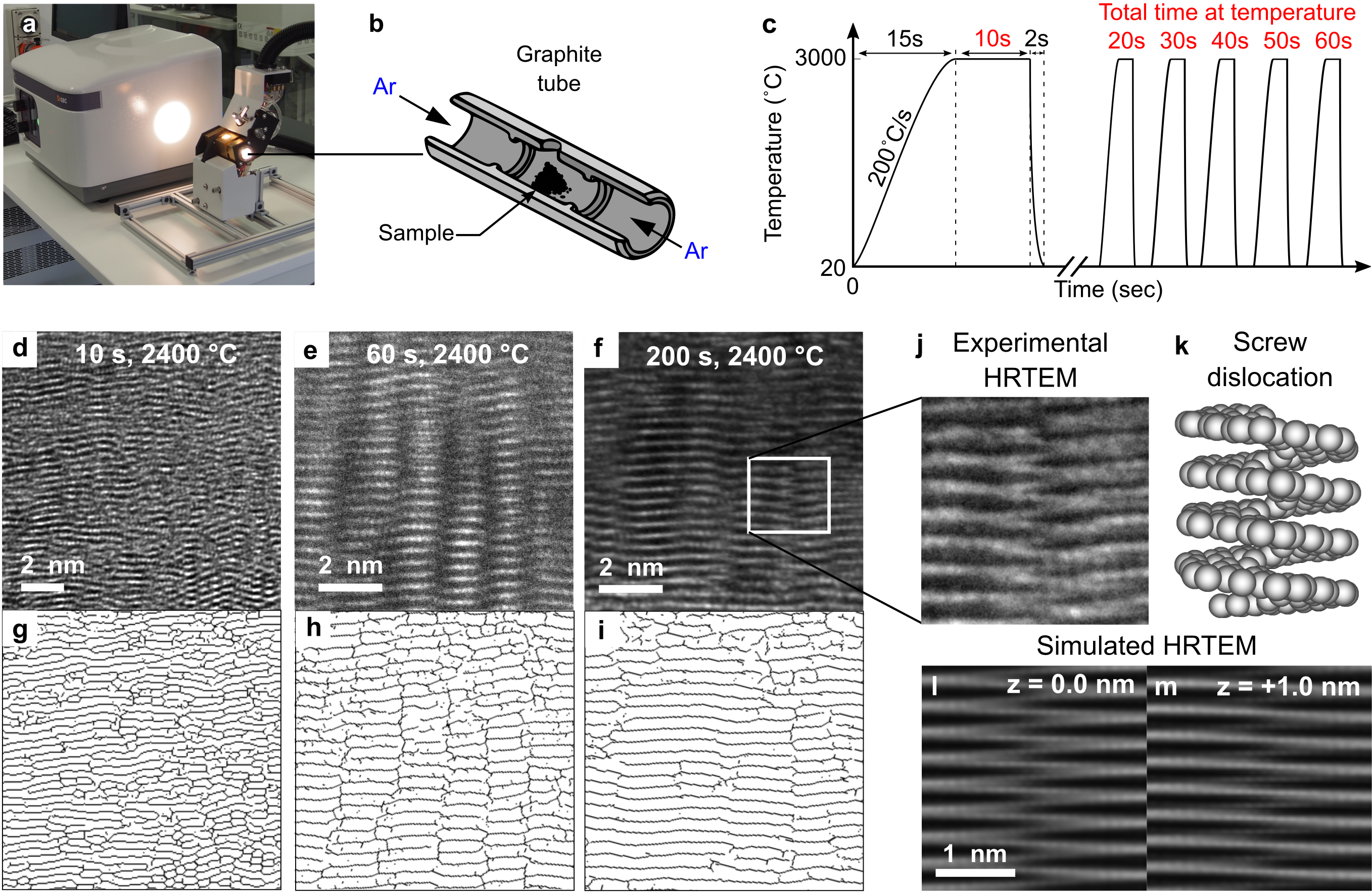
Polyvinyl chloride (PVC) is heated in a custom pulsed graphite furnace[2, 3] that reaches up to 3000 ∘C in seconds (Fig. 1a-c). Repeated pulsing enables the study of graphitisation as a function of temperature and time. HRTEM images in Fig. 1d-f show the time evolution of graphitisation at 2400 ∘C. Figures 1g-i show the same images processed with a skeletonisation algorithm that highlights the dark fringes corresponding to graphenic sheets at the Bragg angle. For the 10 s sample (Fig. 1d,g), small basic structural units (BSUs) are seen where a few layers locally align, but little long-range ordering is observed. After 60 s the fringes and interlayer defects align into columns extending over many tens of layers (Fig. 1e,h). Skeletonisation reveals neighbouring columns are out of phase in the c-direction, normal to the graphenic layers, by half an interlayer distance forming an interdigitated texture. For the 200 s sample (Fig. 1f,i), the columns merge into extended fringes, reducing the number of interlayer defects. These merged fringes are no longer interdigitated but have regions where they bend forming a wrinkled texture, as first noted by Oberlin [1].


We propose that the interdigitated fringes are produced by screw dislocations that connect layers in a helical manner. Figure 1j shows a close-up view of the interdigitated fringes, revealing features that zig-zag between the layers. The zig-zag feature connects the fringes with ramps that can be seen in an atomistic model of the dislocation core (Fig. 1k). To confirm the proposal we compute HRTEM images of screw dislocations at different focal depths with matching instrumental aberrations. Multislice HRTEM simulations of a single screw in AA graphite at focus (Fig. 1l) reproduces the zig-zag ramp texture, while changing the defocus by 1 nm gives a bent wrinkled texture (Fig. 1m). This short focal depth is consistent with our experimental observations that changing the defocus by a few nanometres leads to the appearance and disappearance of zig-zags. We also ruled out beam damage as a possible source of the interdigitated fringes. The beam intensities used during imaging did not lead to any time evolution in the fringes. Additionally, further increasing of the beam intensity led to amorphisation of the samples rather than promoting graphitisation.
Our ability to assign the screw dislocation to the interdigitated fringes is enabled by two breakthroughs. Firstly, the custom pulsed graphite furnace [2] allows for the graphitisation process to be paused. Repeated pulsing allows us to step through graphitisation and probe intermediate structures, isolating single interdigitated fringes for imaging.
Secondly, the use of a cold field emission gun for the TEM enables higher resolution images by removing the thermal broadening of the electron’s beam energy. The higher resolution reveals ramps connecting the interdigitated layers that have not previously been imaged. With the benefit of hindsight, both interdigitated fringes and screws are present in the literature, albeit at lower resolution. For example, TEM by Oberlin [1] and others [5, 6, 7] show textures and general features matching our observations. Screws are a well known defect in graphite and can be observed on the surface of graphite using optical microscopy, electron microscopy and atomic force microscopy [8, 9]. Yakobson et al. even assigned interdigitated fringes to screw dislocations to explain the structure of coal [10]. Leyssale et al. identified screws in their electron microscopy image guided atomistic reconstruction (IGAR) model of irradiated graphite [11]. However, none of these works assigned the defect in the context of graphitisation, nor did they study the time dependence at a fixed temperature.
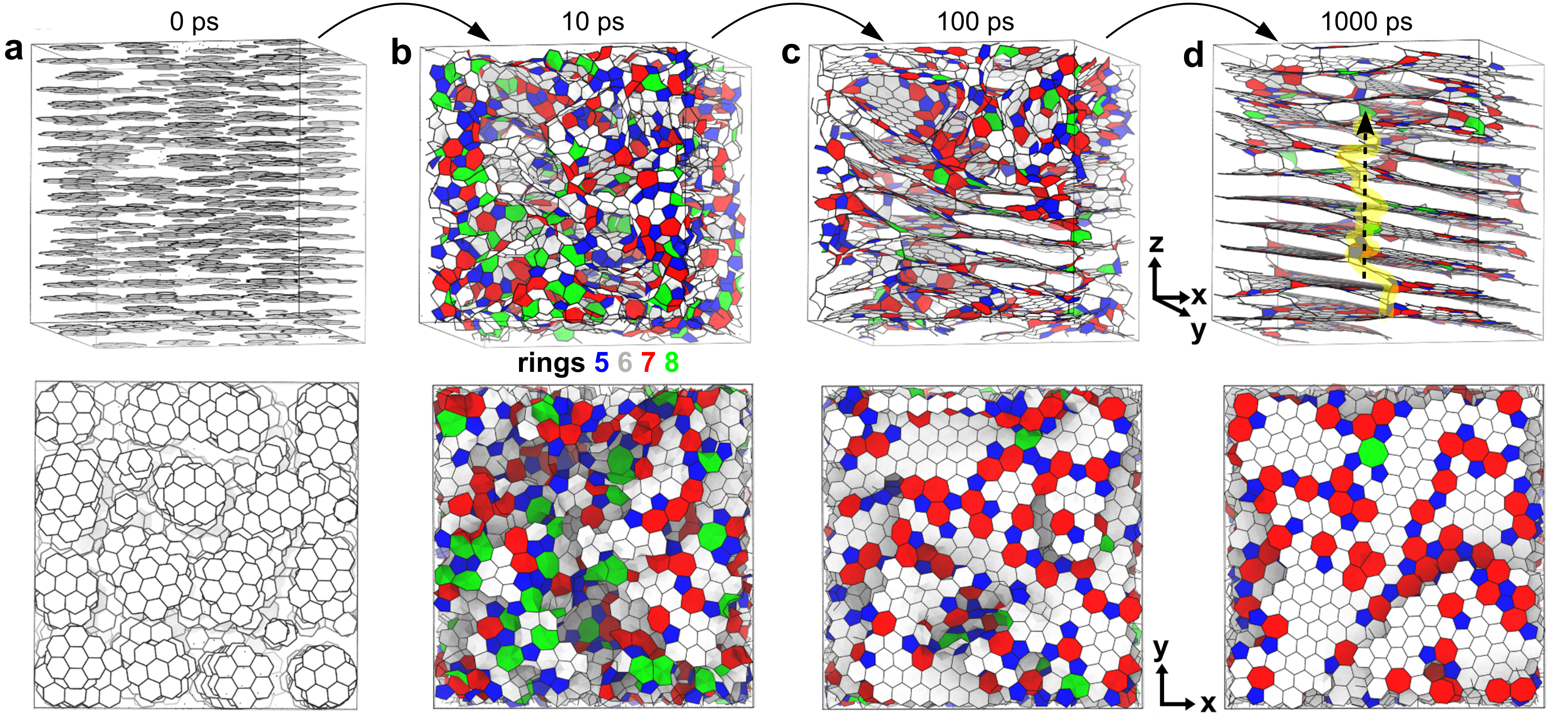
To understand how the screws form and annihilate we performed molecular dynamics simulations at high temperature. Figure 2a shows the initial configuration of graphene fragments (dehydrogenated coronene and benzene) that are parallel to each other but do not form planes. This arrangement mimics the aligned mesophase formed during carbonisation of graphitising carbons [1]. Elevated temperatures of 3200 K were used to enable the dynamics to occur on picosecond timescales. After 10 ps (Fig. 2b), the fragments fuse forming many non-hexagonal rings, which are coloured according to ring number. After 100 ps (Fig. 2c) small stacked regions become visible and extended hexagonal regions develop. By 1000 ps (Fig. 2d) several screw dislocations are formed and the longest screw, highlighted in yellow, runs almost the entire length of the simulation cell. The core of the screws is dominated by sp2 bonded atoms and present slightly distorted versions of the idealised screw shown in Fig. 1k. These simulations reveal that screws spontaneously form from an ordered precursor, merging the graphenic regions in the mesophase that are parallel but are not coplanar.
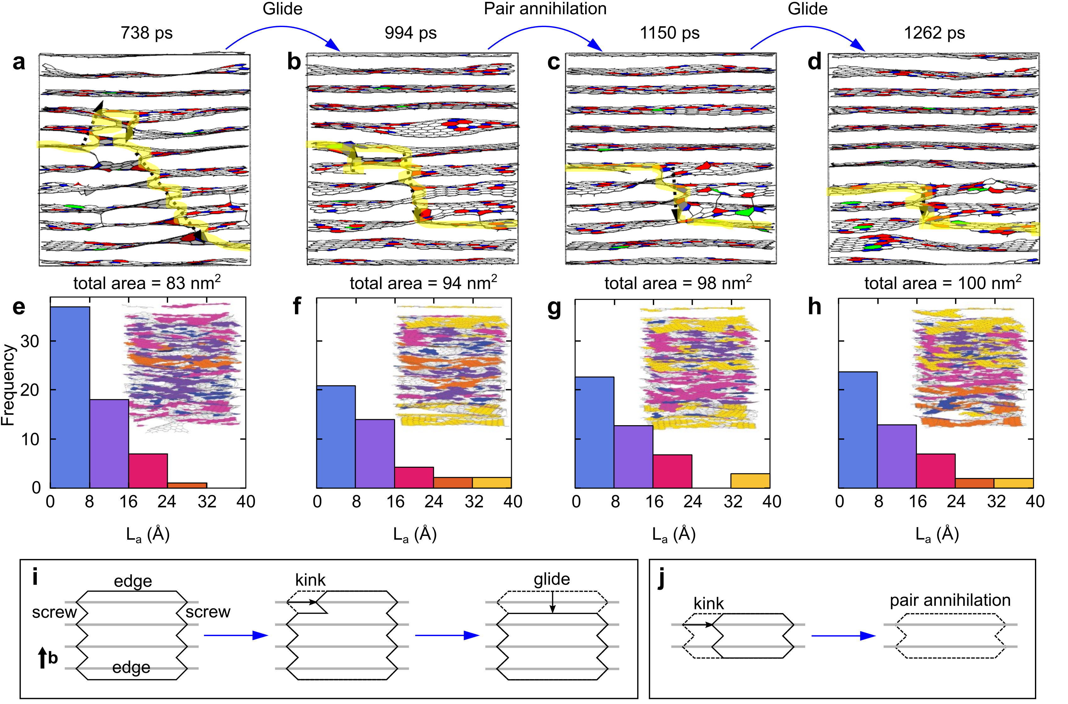
Repeating the MD simulations at a higher temperature of 3500 K shows the annihilation of screw dislocations. Figure 3a-d shows a slice of the system with screw dislocations highlighted in yellow and an arrow in the direction of the dislocation line. As the simulation progresses screws are removed by gliding followed by pair annihilation, which increase the number of perfectly stacked layers. In the upper-left quadrant of Fig. 3a a dislocation loop can be seen where two screws are connected by prismatic edge dislocations. This dislocation loop shrinks through edge gliding that reduces the height of the dislocation loop until it is annihilated. A schematic in Fig. 3i shows the mechanism by which the dislocation shrinks: (i) a kink forms at the boundary between the screw and prismatic edge, (ii) the kink migrates along the edge dislocation, (iii) the edge reaches the opposing screw, reducing the height by one layer. In some circumstances kinks can initiate from all four boundaries and meet in the middle. Once the dislocation loop has shrunk to two layers, it can annihilate in a process which is seen between Fig. 3b and c and shown schematically in Fig. 3j. The annihilation mechanism involves a kink which propagates along basal plane, collapsing the edge dislocations together thereby separating the two layers. A version of this annihilation mechanism was previously modelled with DFT and referred to as a mezzanine defect [12, 13, 14].
The growth of graphenic crystallites can be tracked in the simulation by considering the hexagonal rings that are connected and closely aligned. Figure 3e-h shows a histogram of the crystallite size, La, with an inset showing the structure colour-coded by fragment size. At the beginning of the time series a significant fraction of the crystallites are below 24 Å. After the top layers are freed from the screw defects the total area of the graphenic crystallites is increased from 83 to 94 nm2 and the regions of extended hexagonal rings grow up to 40 Å. This growth is achieved by the removal of non-hexagonal rings through Stone-Wales/Diene transformations [15, 16]. These screw dislocations appear to pin the in-plane growth of graphenic regions in a similar manner to how dislocations can inhibit growth of grain boundaries in metals.
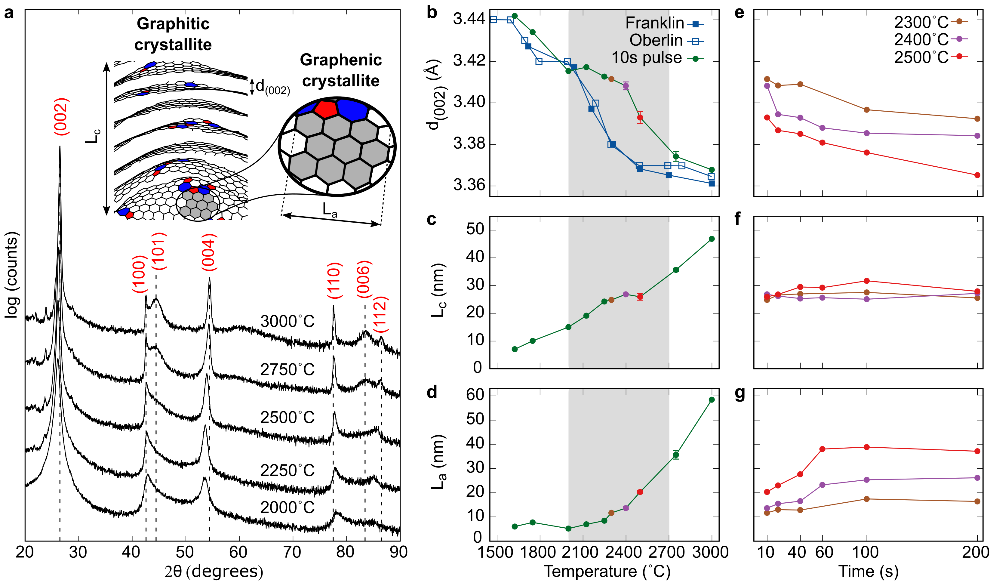
The growth of crystallites during graphitisation can also be tracked via XRD. The most important XRD parameter for studying graphitisation is the interlayer distance which has a minimal value of 3.35Å for graphite. XRD also determines the size of the crystallites via the quantities and (see inset in Fig. 4a). Figure 4a shows the XRD pattern for PVC after a single 10 s pulse. At 3000 ∘C the pattern shows all the signatures of highly graphitised material, including a sharp (002) reflection, (101) and (112) reflections signifying 3D ordering, and higher order (004) and (006) peaks. At 2000 ∘C the 3D peaks are absent and the other peaks are considerably broader, indicating that graphitisation has yet to occur.
Figure 4b-d shows the temperature dependence of the these parameters during the graphitisation transition and are compared with literature data from Franklin [4] and Oberlin [1]. These works used conventional furnaces that take hours to heat and cool [17], meaning samples were at thermodynamic equilibrium. At 3000 ∘C and below 2000 ∘C our parameters match the Franklin and Oberlin data, indicating that 10 s is sufficient to achieve equilibrium. The intermediate regime, highlighted by gray shading, corresponds to a temperature range where equilibrium takes longer than 10 s. The work of Ouzilleau et al. [18] provides another way to think about this region. They analysed data from conventional furnaces and showed that the parameter for all graphitising carbons follow a universal second-order phase transition with a critical temperature of C. We find this critical temperature is shifted to higher temperature of C for the 10 s pulse but the same profile for d(002) versus temperature is observed.
The XRD signature of screws is seen in repeated pulsing measurements in the transition region (Fig. 4e-g). With increasing time, decreases, increases, while remains constant. This observation is in agreement with our assignment of screws, since annihilation increases the basal extent (i.e. increasing La) while leaving the number of layers () unchanged. Single screw dislocations (Burgers vector of one interlayer distance) only form in AA and ABC graphite leading to an interlayer distance at the screw core of 3.5 Å [19]. As the screws are progressively removed the graphenic planes are increasingly able to adopt AB stacking and decreases toward the ideal graphite value of 3.35 Å. Since screws inhibit AB stacking they provide a plausible explanation for so-called turbostratic graphite in which the graphenic planes are in random registration with an interlayer spacing of 3.42 Å [20].
Screw dislocations could also explain the twisting disorder seen in graphite and magnetic states. Moiré patterns have been observed using scanning tunnelling microscopy and electron microscopy these features are caused by layers being twisted relative to each other [21, 22]. Firstly, screws could pin these twisted layers inhibiting the rotation to ideal AB stacking. Secondly, screws provide a twisting force near their core described by the Eshelby twist. For small twist angles exotic magnetic states have been found in twisted bilayer graphene, with a magic angle even enabling a superconducting state [23]. These magnetic states have led to the field of twistronics where 2D layered materials can form useful devices by controlling the twist of their layers. Recently, Moiré pattern with these magnetic properties have been seen in highly oriented pyrolytic graphite (HOPG) [22]. Control of screw defects within carbonaceous materials could potentially enable control of the twist angle and be used for twistronic applications.
The barrier for screw annihilation could be reduced in graphitising materials via chemical or mechanical approaches. For example, metals that are found to catalyse graphitisation [24] may aid in edge gliding. One may imagine mechanical shear [25], twisting or stress could lower the barrier for screws to annihilate. By targeting screw removal, the temperature of graphitisation could be reduced, lowering the cost of synthetic graphite.
This work also sheds light on why so few materials are graphitisable. Ouzilleau et al. explored this question and proposed two classes of defects [26]: annealable defects that are removed in all carbon materials, and non-annealable topological defects that inhibit graphitisation in non-graphitising materials. Our work suggests what these defects might be. Non-hexagonal rings, screw and edge dislocations are all annealable topological defects in graphitising carbons. All these defects were also found in our previous models of non-graphitising carbon [27], where we employed the same annealing procedure as in this paper but started from a completely amorphous configuration. The unique aspect of these non-graphitising carbons is that they possess a foam-like 3D connected structure with net-negative curvature [27]. This net-negative curvature is enabled by disclinations, which should not be conflated with simply non-hexagonal rings but describe a surface that cannot be flattened (or in the language of topology, non-developable). Combining our two models we can assign Ouzilleau’s defects: non-hexagonal rings, screw and edge dislocations are annealable and present in all carbons, while disclinations are non-annealable defects and inhibit graphitisation. For most carbonaceous precursors, carbonisation leads to crosslinking in three dimensions that results in disclinations. This makes early parallel alignment during carbonisation critical for discouraging disclination formation and explains why the most common approach is using a precursor that decomposes into a mesophase with aligned aromatic molecules. Alignment of the mesophase provides a retrospective explanation for the many approaches (shear in carbon fibres [5], stress in HOPG [28] and 2D templating [29]) that have been empirically developed to promote graphitisation.
In summary, we identify screw dislocations as the key defect in graphite formation. Using computer simulations, we provide an atomistic mechanism for screw formation and annihilation, which is consistent with transmission electron microscopy and X-ray diffraction. Efforts to target this defect will be key to lowering the cost of synthetic graphite and enabling more materials to be converted into graphite.
Methods
Preparation of carbonised and graphitised samples
Polyvinyl chloride was heated in a STF 1200 tube furnace over four hours to a carbonisation temperature of 1000∘C. The temperature was held for a further hour before passively cooling to room temperature. Argon, flowing at a constant 1.5-2 L/min maintained an inert atmosphere. The carbonised sample was then milled in a mortar and pestle before further heating.
Temperatures above 1000∘C were achieved using a customised furnace built by GBC Scientific Equipment. The system separates the joule heated graphite tube of an atomic absorption spectrometer from the spectrometer, leaving a bench top unit capable of heating to 3000∘C in 1–2 seconds. Elevated temperatures can be maintained for several tens of seconds, whilst an inert cooling gas, typically argon, is followed through the tube to prevent combustion. Operation in a pulsed mode extends time at elevated temperature, a short pause between pulses allows the cooling system to manage the thermal load. The temperature profile for heating pulses is as follows: room temperature - 100∘C in 5 seconds, ramping to desired temperature at 200∘C/s, holding desired temperature for a further 10 seconds before cooling to room temperature over a few seconds. The graphite tube holds samples on the tens of milligram scale.
Characterisation of partially graphitised material
X-Ray Diffraction (XRD) is performed in a Bruker D8 Advance Diffractometer with Bragg-Brentano geometry and a Cu K- source. XRD specimens are prepared by placing a powder sample onto a low signal silicon wafer holder. Patterns are collected over a 2 range of 10-90∘ with a dwell time of 1.5 seconds and step size of 0.3∘. Further information regarding the device configuration can be found in Ref. [2]. Transmission electron microscopy samples are prepared by grinding with ethanol in an agate mortar, the suspension is sonicated before deposition on 300 mesh lacey carbon grids. A JEOL F200 TEM fitted with a cryogenic electron source is used to analyse samples nanostructure. With an accelerating voltage of 200 KeV the cold field emission gun produces a coherent electron beam which allows images to be collected with a low surface current. Specific care is taken to minimise beam damage by limiting sample time under the beam and using low beam intensities. Skeletonisation was performed based on the previously developed methodology from Botero et al. but re-implemented in python with skimage with the thresholding approach of Zack et al. [30] replacing the Otsu method provided more interplanar features.
Simulations
Initial atomic configurations were prepared by packing coronene fragments of the same orientation into a 4 nm size cube using the software packmol [31], benzene fragments were then added until the density reached 2 g/cc. The carbon environment dependent interatomic potential (EDIP) was used to describe the energy of the carbon network [32], which has been shown to accurately describe the bonding in sp2 to sp3 carbons [33]. The structures were minimised and molecular dynamics simulations performed using the software LAMMPS [34]. The Bussi thermostat maintained the temperature during the simulation [35]. The results were processed in polypy [36] to extract the rings using the Franzblau ring algorithm [37] and custom scripts extracted graphenic regions. Finally, all of the visualisations were rendered in the software VMD [38]. Atomsk [39] was used to generate screw dislocations in AA graphite. Multislice software compuTEM [40] was then used to simulate the HRTEM images of the dislocations using aberrations matching those of the instrument.
References
- [1] Oberlin, A. Carbonization and graphitization. \JournalTitleCarbon 22, 521 – 541, DOI: 10.1016/0008-6223(84)90086-1 (1984).
- [2] Putman, K. et al. Pulsed thermal treatment of carbon up to 3000 °C using an atomic absorption spectrometer. \JournalTitleCarbon 135, 157–163, DOI: 10.1016/j.carbon.2018.03.060 (2018).
- [3] Fogg, J. L. et al. Catalysis-free transformation of non-graphitising carbons into highly crystalline graphite. \JournalTitleCommunications Materials 1, 1–7 (2020).
- [4] Franklin, R. E. The structure of graphitic carbons. \JournalTitleActa crystallographica 4, 253–261 (1951).
- [5] Ghazinejad, M., Holmberg, S., Pilloni, O., Oropeza-Ramos, L. & Madou, M. Graphitizing non-graphitizable carbons by stress-induced routes. \JournalTitleScientific reports 7, 1–10 (2017).
- [6] Tulić, S. et al. Covalent diamond–graphite bonding: Mechanism of catalytic transformation. \JournalTitleACS nano 13, 4621–4630 (2019).
- [7] Mubari, P. K. et al. The x-ray, raman and tem signatures of cellulose-derived carbons explained. \JournalTitleC 8, 4 (2022).
- [8] Hennig, G. R. Screw dislocations in graphite. \JournalTitleScience 147, 733–734, DOI: 10.1126/science.147.3659.733 (1965).
- [9] Rakovan, J. & Jaszczak, J. A. Multiple length scale growth spirals on metamorphic graphite 001 surfaces studied by atomic force microscopy. \JournalTitleAmerican Mineralogist 87, 17–24 (2002).
- [10] Sun, Y., Alemany, L. B., Billups, W. E., Lu, J. & Yakobson, B. I. Structural dislocations in anthracite. \JournalTitleThe Journal of Physical Chemistry Letters 2, 2521–2524, DOI: 10.1021/jz2011429 (2011).
- [11] Leyssale, J.-M., Costa, J.-P. D., Germain, C., Weisbecker, P. & Vignoles, G. L. Structural features of pyrocarbon atomistic models constructed from transmission electron microscopy images. \JournalTitleCarbon 50, 4388 – 4400, DOI: 10.1016/j.carbon.2012.05.015 (2012).
- [12] Trevethan, T. et al. Extended interplanar linking in graphite formed from vacancy aggregates. \JournalTitlePhysical Review Letters 111, 095501 (2013).
- [13] Vuong, A. Nanocarbon: Defect Architectures and Properties. Ph.D. thesis, University of Surrey (United Kingdom) (2017).
- [14] Vuong, A. et al. Interlayer vacancy defects in aa-stacked bilayer graphene: density functional theory predictions. \JournalTitleJournal of Physics: Condensed Matter 29, 155304 (2017).
- [15] Dienes, G. J. Mechanism for self-diffusion in graphite. \JournalTitleJournal of Applied Physics 23, 1194–1200 (1952).
- [16] Wales, D. J., Miller, M. A. & Walsh, T. R. Archetypal energy landscapes. \JournalTitleNature 394, 758–760, DOI: 10.1038/29487 (1998).
- [17] Chung, D. Review graphite. \JournalTitleJournal of materials science 37, 1475–1489 (2002).
- [18] Ouzilleau, P., Gheribi, A. E. & Chartrand, P. The graphitization temperature threshold analyzed through a second-order structural transformation. \JournalTitleCarbon 109, 896–908 (2016).
- [19] Martínez, I. S. Theory of diffusion and plasticity in layered carbon materials. Ph.D. thesis, University of Sussex (2007).
- [20] Puech, P., Dabrowska, A., Ratel-Ramond, N., Vignoles, G. L. & Monthioux, M. New insight on carbonisation and graphitisation mechanisms as obtained from a bottom-up analytical approach of x-ray diffraction patterns. \JournalTitleCarbon 147, 602–611 (2019).
- [21] Campanera, J., Savini, G., Suarez-Martinez, I. & Heggie, M. Density functional calculations on the intricacies of moiré patterns on graphite. \JournalTitlePhysical review B 75, 235449 (2007).
- [22] Boi, F. S. et al. Interplay of edge/screw dislocations and enhanced magnetism in exfoliated pyrolytic graphite with distorted hexagonal moiré superlattices. \JournalTitleCarbon Trends 5, 100106 (2021).
- [23] Cao, Y. et al. Unconventional superconductivity in magic-angle graphene superlattices. \JournalTitleNature 556, 43–50 (2018).
- [24] Ōya, A. & Ōtani, S. Catalytic graphitization of carbons by various metals. \JournalTitleCarbon 17, 131–137 (1979).
- [25] Bonijoly, M., Oberlin, M. & Oberlin, A. A possible mechanism for natural graphite formation. \JournalTitleInternational Journal of Coal Geology 1, 283–312 (1982).
- [26] Ouzilleau, P., Gheribi, A. E., Chartrand, P., Soucy, G. & Monthioux, M. Why some carbons may or may not graphitize? the point of view of thermodynamics. \JournalTitleCarbon 149, 419–435 (2019).
- [27] Martin, J. W., de Tomas, C., Suarez-Martinez, I., Kraft, M. & Marks, N. A. Topology of disordered 3D graphene networks. \JournalTitlePhysical Review Letters 123, 116105, DOI: 10.1103/PhysRevLett.123.116105 (2019).
- [28] Blackman, L. & Ubbelohde, A. R. J. P. Stress recrystallization of graphite. \JournalTitleProceedings of the Royal Society of London. Series A. Mathematical and Physical Sciences 266, 20–32 (1962).
- [29] Nishihara, H. & Kyotani, T. Templated nanocarbons for energy storage. \JournalTitleAdvanced Materials 24, 4473–4498 (2012).
- [30] Zack, G. W., Rogers, W. E. & Latt, S. A. Automatic measurement of sister chromatid exchange frequency. \JournalTitleJournal of Histochemistry & Cytochemistry 25, 741–753 (1977).
- [31] Martinez, L., Andrade, R., Birgin, E. G. & Martínez, J. M. PACKMOL: A package for building initial configurations for molecular dynamics simulations. \JournalTitleJournal of Computational Chemistry 30, 2157–2164, DOI: 10.1002/jcc.21224 (2009). NIHMS150003.
- [32] Marks, N. A. Generalizing the environment-dependent interaction potential for carbon. \JournalTitlePhysical Review B 63, 035401, DOI: 10.1103/PhysRevB.63.035401 (2000).
- [33] de Tomas, C., Suarez-Martinez, I. & Marks, N. A. Graphitization of amorphous carbons: A comparative study of interatomic potentials. \JournalTitleCarbon 109, 681–693, DOI: 10.1016/j.carbon.2016.08.024 (2016).
- [34] Plimpton, S. Fast Parallel Algorithms for Short-Range Molecular Dynamics. \JournalTitleJournal of Computational Physics 117, 1–19 (1995).
- [35] Bussi, G., Donadio, D. & Parrinello, M. Canonical sampling through velocity rescaling. \JournalTitleThe Journal of chemical physics 126, 014101 (2007).
- [36] Kroes, J., Fasolino, A. & de Wijs, G. Graphene nanoribbons and edge reconstructions. Ph.D. thesis, Radboud University Nijmegen (2010).
- [37] Franzblau, D. S. Computation of ring statistics for network models of solids. \JournalTitlePhysical Review B 44, 4925–4930, DOI: 10.1103/PhysRevB.44.4925 (1991).
- [38] Humphrey, W., Dalke, A. & Schulten, K. VMD: Visual molecular dynamics. \JournalTitleJournal of Molecular Graphics 14, 33–38, DOI: 10.1016/0263-7855(96)00018-5 (1996).
- [39] Hirel, P. Atomsk: A tool for manipulating and converting atomic data files. \JournalTitleComputer Physics Communications 197, 212–219 (2015).
- [40] Kirkland, E. J. Advanced Computing in Electron Microscopy (Springer US, Boston, MA, 2010).
Acknowledgements
The authors would like to thank Assoc. Prof. Martin Saunders for his help in collecting the HRTEM images.
J.W.M. acknowledges the support of the Forrest Research Foundation.
I.S.-M. acknowledges the support of the Australian Research Council (No. FT140100191).
Characterisation of the samples were undertaken at the John de Laeter Centre, Curtin University.
Computational resources were provided by the Pawsey Centre with funding from the Australian Government and the Government of Western Australia.
The authors acknowledge the facilities, and the scientific and technical assistance of Microscopy Australia at the Centre for Microscopy, Characterisation & Analysis, The University of Western Australia, a facility funded by the University, State and Commonwealth Governments.
Author contributions
J.W.M. and J.L.F. carried out the experimental work. J.W.M., K.J.P., G.F., E.P.T., N.A.M and I.S.-M. carried out the modelling and analysis. All authors discussed and co-wrote the manuscript.
Competing interests
The authors declare no competing interests.