Faraday conversion in pair-symmetric winds of magnetars and Fast Radio Bursts
Abstract
We consider propagation of polarization in the inner parts of pair-symmetric magnetar winds, close to the light cylinder. Pair plasmas in magnetic field is birefringent, a effect. As a result, such plasmas work as phase retarders: Stokes parameters follow a circular trajectory on the Poincare sphere. In the highly magnetized regime, , the corresponding rotation rates are independent of the magnetic field. A plasma screen with dispersion measure DM pc cm-3 can induce large polarization changes, including large effective Rotation Measure (RM). The frequency scaling of the (generalized) RM, , mimics the conventional RM with for small phase shifts, but can be as small as . In interpreting observations the frequency scaling of polarization parameters should be fitted independently. The model offers explanations for (i) large circular polarization component observed in FRBs, with right-left switching; (ii) large RM, with possible sign changes; (iii) time-depend variable polarization. Relatively dense and slow wind is needed - the corresponding effect in regular pulsars is small.
1 Polarization of FRBs: the challenges
Polarization properties of FRBs defy simple classification Caleb et al. (2019); Petroff et al. (2019), (“some FRBs appear to be completely unpolarized, some show only circular polarization, some show only linear polarization, and some show both,” Petroff et al., 2019). Understanding polarization behavior is the key to understanding FRBs.
Even in the sub-set of linearly polarized FRBs, there is no clear trend:
-
•
FRB 150807 (Ravi et al., 2016) was nearly 80% linearly polarized, but very small RM=12 at DM=266 (in usual astronomical unites); the average inferred magnetic field G.
-
•
FRB 110523 (Masui et al., 2015), RM=186, DM=623, G
-
•
FRB180301 (Price et al., 2019), RM = , DM=522, G.
-
•
FRB121102 (Michilli et al., 2018) was 100% linearly polarized, (varying!) RM = , DM=559, G. At the observed frequency of 4.5 GHz this corresponds to the PA rotation by 360 radians; this is a model-independent quantity to be explained (in a sense that a value of RM assumes a particular frequency scaling of the rotation of polarization).
-
•
The case of FRB20190520B (Dai et al., 2022) is particularly interesting: it shows large fluctuations of linear polarization (from to , large fluctuations of circular polarization with changing sign () and large fluctuations of RM, also with changing sign ()
-
•
no correspondingly large changes of DM are seen.
We make the following conclusion: polarization model should explain not the average properties, but the extremes of the behavior. Models should account for large variations in polarization properties, both between different sources, temporal variations in a given source, and unusual polarization behavior like in FRB180301 and FRB20190520B.
Fast temporal variation of RM seen in FRB 121102 (Michilli et al., 2018) and FRB20190520B (Dai et al., 2022) are especially demanding, as this implies that the RM comes from a relatively compact region. This would normally require small and extremely dense region, yet no DM variations are seen. (In our model the region is small, but not dense.)
In this paper we consider polarization propagation effects in the near wind zone of the central magnetar, somewhat outside the light cylinder. We demonstrate that the model naturally explains a broad range of polarization behavior. Switching of the signs of circular polarization, and of the (generalized) Rotation measure are especially noteworthy. We also mention related papers by Vedantham & Ravi (2019) and Gruzinov & Levin (2019) (in passing we note a minor error: their parameters and should be interchanged).
Previously a number of works considered PA rotation effect inside the pulsar magnetosphere Cheng & Ruderman (1979); Barnard (1986); Petrova & Lyubarskii (2000); Wang et al. (2010); Beskin & Philippov (2012). Inside the pulsar magnetosphere, the PA rotation and the generation of V component are suppressed by a combination of effects: (i) for parallel propagation in symmetric pair plasma the Faraday effect is absent; the contribution to the PA rotation comes either from a slight charge-disbalance, different Lorentz factors, or from oblique propagation (Kazbegi et al., 1991a; Lyutikov, 1999) - all these effects producing weak contribution (due to small “active” density and/or small angle of propagation). Relativistic motion of plasma also reduces the effective plasma frame density, and stretching of the corresponding time scale in the lab frame; this is effect is also important in the present model. In contrast to the magnetospheres, in the near wind zone it is the total plasma density that contributes to the PA rotation, via the effects of birefringence.
2 Polarization propagation in birefringent symmetric pair plasma
2.1 Faraday and Cotton-Mouton/Voigt effects
Two somewhat different effects contribute to the changes of polarization as the light propagates in plasma: the Faraday effect and the Cotton-Mouton/Voigt effects (Landau & Lifshitz, 1960). Qualitatively, the Faraday effect is that a linearly polarized wave propagating along the magnetic field can be decomposed into two circularly polarized waves. In the electron-ion plasma the two circularly polarized waves have different phase velocity - their final addition leads to the rotation of the position angle (PA). The rate of rotation of the polarization angle due to the Faraday effect is (Ginzburg & Syrovatskii, 1965, Eq. (4.6)) is
| (1) |
where is the difference in the refractive index of two circularly polarized normal modes. This effect is linear in magnetic field. It disappears in symmetric pair plasma.
The Cotton-Mouton/Voigt effects appear because for oblique propagation (with respect to the magnetic field), the two plasma modes, usually called O (ordinary) and X (extraordinary), have different phase velocities. If the initial wave had contribution from both X and O modes, the final addition of the retarded waves leads to elliptical polarization, hence both to the rotation of the position angle of linearly polarized component, and to the appearance of circular polarization. This effect is quadratic in magnetic field– it appears both in symmetric and non-symmetric plasmas.
Following the tradition we call polarization transformation as Faraday Conversion (FC), with a clear understanding of the different origin of the circular component, as discussed above.
2.2 Waves in symmetric pair plasma
Waves in pair plasma has been considered in a number of publications (Arons & Barnard, 1986; Kazbegi et al., 1991b; Lyutikov, 1999) we follow Lyutikov (2007). Let us consider the simplest case of cold plasma, in plasma frame. For plasma in magnetic field the dispersion relation factorizes giving two modes: the X mode with the electric vector perpendicular to the k-B plane and two branches of the longitudinal-transverse mode, which we will call O and Alfvén waves, with the electric vector in the k-B plane (Arons & Barnard, 1986, see Fig. 1). X waves is a subluminal (for ) transverse electromagnetic wave with a dispersion relation
| (2) |
here is refractive index, is cyclotron frequency, is a plasma frequency of each species (so that for pair plasma the total plasma frequency is ). The Alfvén-O mode satisfies the dispersion relation
| (3) |
Alfvén branch is always subluminal while O mode is superluminal at small wave vectors and subluminal at large wave vectors.

2.3 Faraday Conversion in magnetized pair plasma
Consider propagation of electromagnetic radiation along direction perpendicular to the magnetic field, which is in the direction, Fig. 2
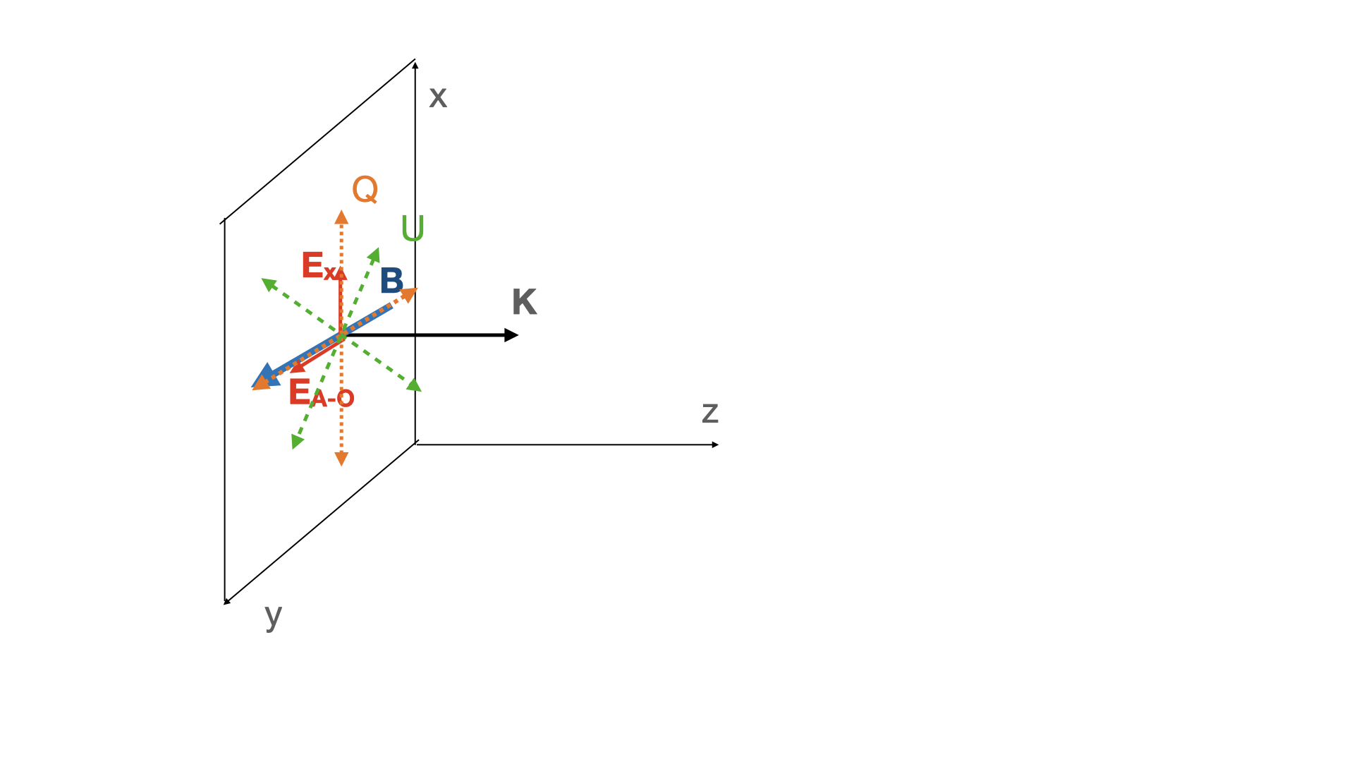
The X-mode is then polarized along and A-O-mode along . Let at the point the wave be linearly polarized with the unit Jones (Born & Wolf, 1980) vector
| (5) |
The medium works as a retarder. The key parameter is a phase lag (retardance) :
| (6) |
In the limit ,
| (7) |
where is the difference of the refractive indices of the two linearly polarized modes, with assumed; the limit ”” here and below corresponds to the relevant case of ; dimension of is cm-2. In the last relation is in centimeters and DM is the dispersion measure in pc cm-3.
It may be convenient to define the magnetic Conversion Measure (CMB) as
| (8) |
It is different from the low magnetic field Conversion Measure (CM)
| (9) |
where magnetic field is in Gauss.
Relations (7-8) demonstrates that in magnetically-dominated plasma a screen with DM pc cm-3 can induce polarization changes (rotation of PA of linear component, as well as production of circular component) of the order of unity. This is one of the major points of the work.
Using Jones’ calculus, at any location the polarization can be characterized by a vector
| (12) | |||
| (15) |
is Jones’ matrix.
The corresponding Stokes parameters (normalized to unity; fully polarized wave is assumed) are
| (16) |
Polarization transfer equation can be written as
| (17) |
is the angular frequency of the polarization rotation rate on the Poincare sphere.
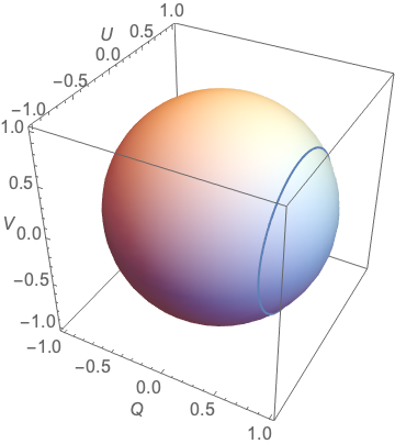
The corresponding Mueller matrix
| (18) |
Thus, there are periodic oscillations. (It can be called generalized Faraday conversion, but the proper Faraday effect - as opposed to Cotton-Mouton effect - is not involved in this case).
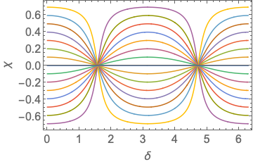
Thus, in symmetric pair plasma there is efficient transformation of Stokes parameters and , in a way similar to the laboratory phase retarders. The key parameter for the rate is the retardance , Eq. (7). The rotation of polarization/production of the circular component in pair plasma disappears only for with ; this corresponds to either pure X mode () or pure A-O mode ().
2.4 Frequency scaling of Generalized Faraday Rotation
In plasma the retardance (7) and the rotation angle (20) are wave length-dependent. The polarization angle scales as
| (21) |
Relation (21) can be interpreted as a Generalized Faraday Rotation (GFR): frequency-dependent PA. Note that when the retardance crosses the sign of , and the corresponding RM, changes (Dai et al., 2022)
At small the frequency dependent part of the PA scales as
| (22) |
Thus, frequency scaling matches the Faraday effect. But the polarization rotation in this limit is independent of the magnetic field (and hence cannot be used to estimate it). We can introduce effective RM, ,
| (23) |
(factor of converts from cgs unites to m-2). Thus, to produce RM = in FRB121102 (Michilli et al., 2018) the required DM is only .
At special moments when we find from (20)
| (24) |
At this point circular component is large. Note that in both cases and the rotation angle is independent of the magnetic field.
Generally we can write
| (25) |
In astrophysical literature this is usually called Generalized Faraday Rotation.
In conclusion, we arrived at two important results: (i) there is efficient production of circular component in symmetric pair plasma; (ii) the corresponding frequency scaling (in the regime) matches the Faraday rotation. Thus, for the observed radio signal, if , which is the rotation angle difference between the top and bottom frequency, is much smaller than 1 radian, the Generalized Faraday rotation may be confused with Faraday rotation and misinterpreted as large RM or sign change of RM (although in the case of FRB 20190520B, the observed change of PA against frequency is large enough to distinguish different effects.)
In what follows we apply the general relations derived above to relativistically streaming plasma in the inner parts of the pulsar/magnetar winds.
2.5 Faraday Conversion in electron-ion plasma
All the above relations, when expressed in terms of retardance , Eq. (6), are applicable to regular electrons-ion plasma for propagation orthogonally to the magnetic field, when the normal modes are linearly polarized. In particular, a term similar to the limit in (4) appears also in non-symmetric plasma. In that case for wave propagating orthogonal to the magnetic field,
| (26) |
The principles of Faraday conversion remain the same: in a frame defined in Fig. 2, the Stokes Q remains constant while U and V experience oscillations. The rotation direction on the Poincare sphere , Eq. (17), is still aligned with Q.
In regular plasma at small the retardance is, see Eqns. (26) and (6),
| (27) |
It has different sign and different frequency scaling than the case. The motion on the Poincare sphere in this case proceeds in the opposite sense around Q axis (counter-clockwise instead of clockwise).
The sense of rotation on the Poincare sphere cannot be used to distinguish the two cases observationally: the Q-U separation is observer-dependent (typically Q is chosen along the direction to the north). There is then a freedom in rotation on the Poincare sphere around V axis. Qualitatively: the difference between the phase speeds of the X-mode and the A-O-mode changes sign at the resonance, but observationally we do not know the direction of the magnetic field: hence cannot define which mode is which: a change of magnetic field direction by “flips” the observational definition of the X and A-O-modes.
3 Magnetar/pulsar winds
3.1 Particle dynamics in the inner wind,
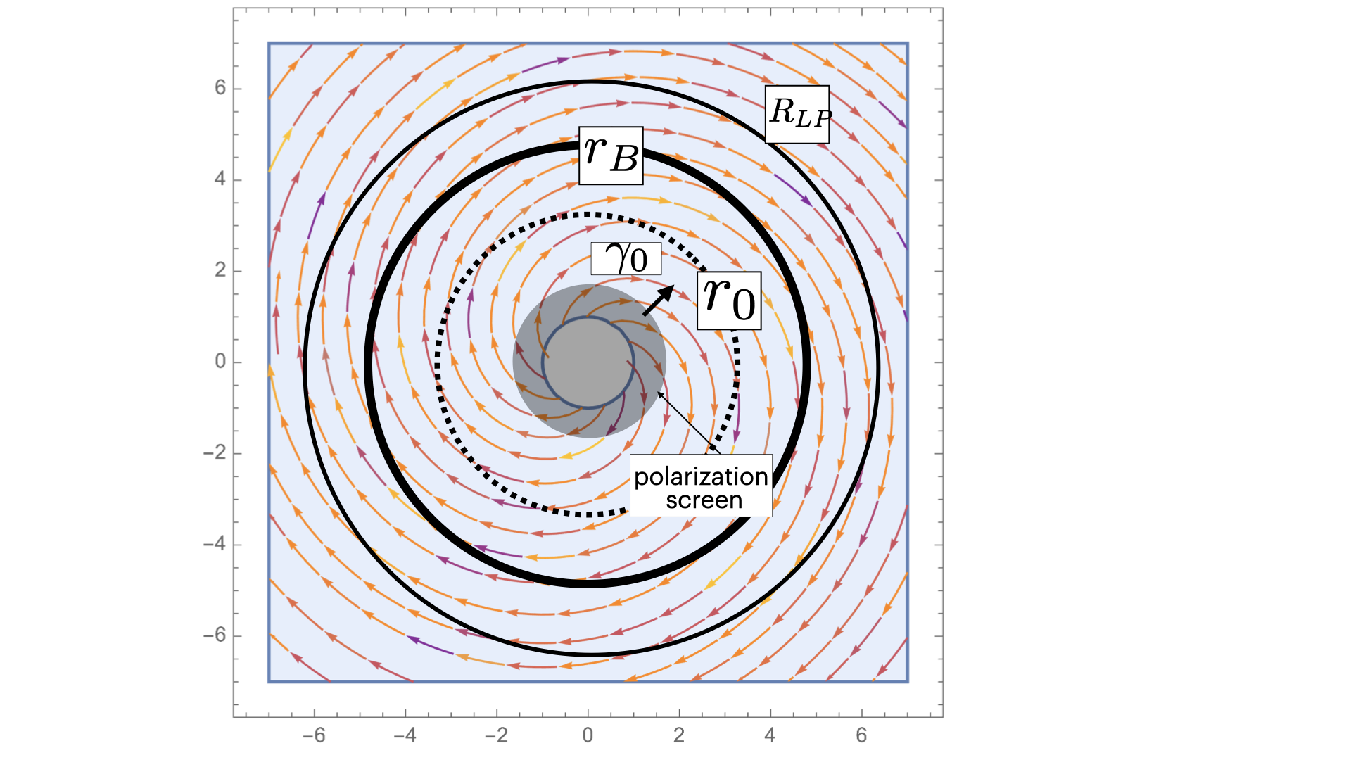
Let us consider motion of particles in the inner wind with Michel (1973b) magnetic field and assuming that particles moves exclusively along the field (“bead-on-wire” approximation”). This is best done using machinery of General Relativity (Landau & Lifshitz, 1975).
In spherical coordinates, changing to the rotating system of coordinates , and assuming that particles move along the Archimedean spiral with
| (29) |
at fixed polar angle , we find the metric tensor
| (30) |
The Hamilton-Jacobi equation
| (31) |
for the action functional , with separation becomes
| (32) |
The Lorentz factor comes mostly from the motion of particles along the magnetic field.
This can be integrated to find . Differentiating the result with respect to we find
| (33) |
Eq. (33) gives implicit solution for motion of a bead along the Michel-type magnetic field lines; time is chosen at the moment when the particle crosses the light cylinder, .
By differentiating with respect to time we find coordinate velocity
| (36) | |||
| (37) |
The toroidal component of the velocity
| (38) |
remains small; it’s maximal value is reached at and equals (at ). Particles move nearly radially.
Relation (37-38) requires some explanation. Motion of particles consists of (i) bulk E-cross-B drift and (ii) motion along the field. The bulk E-cross-B drift has two components: radial and toroidal (Michel, 1973a)
| (39) |
In the inner part of the wind the unit magnetic field vector
| (40) |
quickly becomes toroidal (the field lines intersect the light cylinder at ). As a result, near the light cylinder the large azimuthal drift velocity is mostly compensated by the azimuthal component of the parallel velocity, resulting in nearly radial motion with relativistic Lorentz factor . Particles stream radially with Lorentz factor (injection Lorentz factor). The EM waves propagate across magnetic field, .
In conclusion, in the inner part of the wind, somewhat outside the light cylinder particles move nearly radially with the Lorentz factor determined by the acceleration processes inside the magnetosphere.
3.2 Wind parameters
Let us parametrize the properties of the wind by wind luminosity and the ratio of Poynting to particle fluxes :
| (41) |
Terminal Lorentz factor of the wind is ; it is reached at ,
| (42) |
(Michel, 1969; Goldreich & Julian, 1970; Michel, 1973b). Requirement of then gives . This is a requirement that the terminal Lorentz factor is determined by the wind acceleration, not by the injection.
If density is scaled to Goldreich & Julian (1969) density , then
| (43) |
3.3 Cyclotron resonance
One of the key issues is the location the cyclotron resonance . For a given frequency (in the observer frame) the cyclotron resonance occurs at
| (44) |
where period is in seconds. (Note that for Crab pulsar, seconds, the cyclotron resonance occurs at .) Relation (44) is independent of the Lorentz factor of the wind.
3.4 Limiting polarization radius
Separation of modes into X and O branches may be violated if the rate of change of plasma parameters is sufficiently fast, so that the mode propagation becomes non-adiabatic (the effect of limiting polarization Budden, 1952). This occurs when the wavelength of the beat between two modes becomes larger than the scale at which the properties of the modes change. In our case this condition becomes
| (45) |
where is the Lorentz factor of the wind, which follows from (37). This is a condition that propagation is adiabatic.
The condition for limiting polarization becomes
| (46) |
Location of the limiting polarization radius is thus highly dependent on the parameter . For definiteness as assume .
4 Polarization transfer in magnetar winds
4.1 Retardance and Generalized Rotation Measure in the wind
Let us assume the following scaling in magnetar winds: , see Fig. 6, so that the cyclotron radius is outside the constant Lorentz factor region . Let us consider polarization transformation in the regions , where and the Lorentz factor is constant .
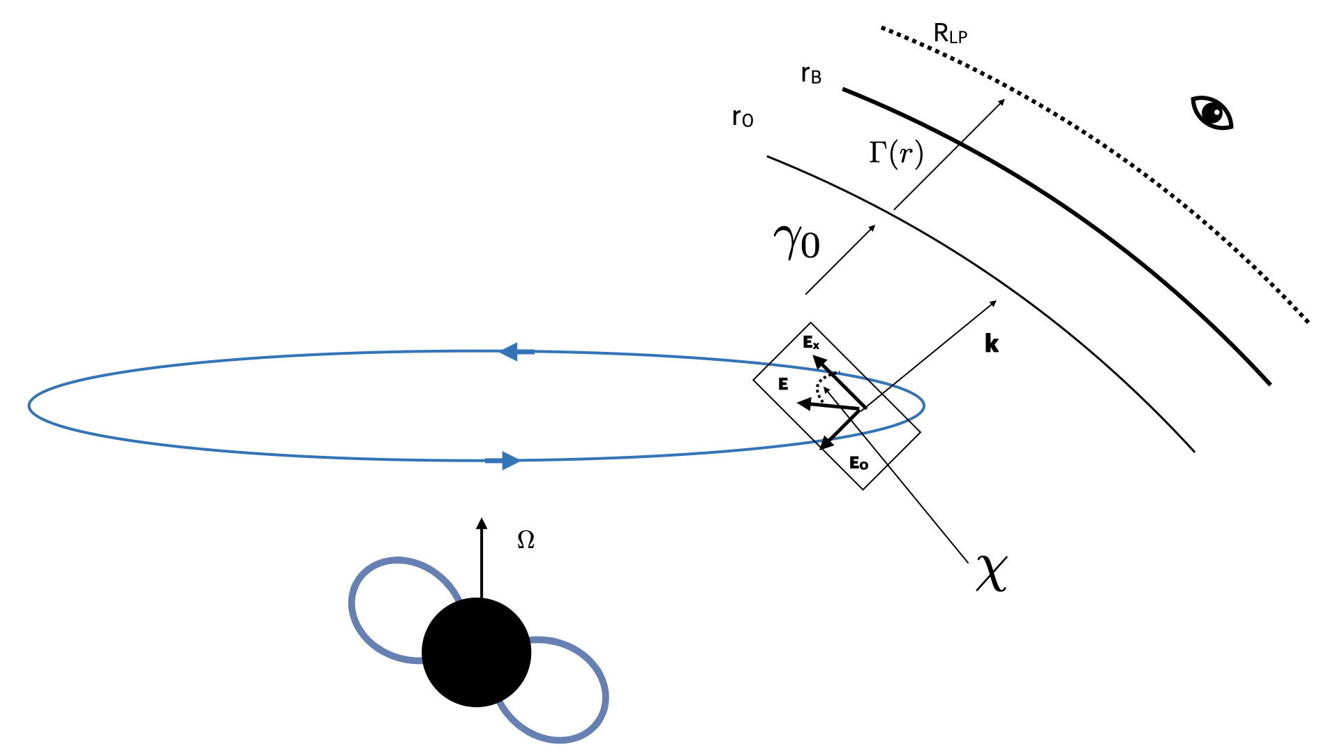
As we demonstrated in §3.1 azimuthal motion of particles can be neglected. The wind can then be approximated as a sequences of toroidal magnetic loops moving away from the light cylinder. The EM waves propagate across magnetic field, through relativistically moving wind.
In this regime the Lorentz factor of the particles is , and . The rate of retardance in the wind frame
| (47) |
Transformation to lab frame gives
| (48) |
(values of and transform similarly, while the rate is smaller in the observer frame.)
Estimating , density according to (41), we find
| (49) |
The key dependence is on the combination of parameters . It is very large, a product of two large numbers. For example, for Crab pulsar with multiplicity , this gives ; for typical few , we find .
To get large phase shift requires
| (50) |
(period in seconds).
To produce an observed RM of value , the ratio of Poynting to particle fluxes and the streaming Lorentz factor should satisfy the condition
| (52) |
(smaller implies larger observer frame density, smaller implies less time dilation).
In particular for inferred by Michilli et al. (2018) it is required that
| (53) |
Relations (49-51) are our main results. They provide estimates of the retardance and the Rotation Measure through the inner part of the wind (expression for the RMeff assumes ).
Models of pair creation in the pulsar magnetospheres (Ruderman & Sutherland, 1975; Arons & Scharlemann, 1979; Timokhin, 2010) typically predict and similarly for . Thus, for Crab pulsar and , Eq. (43)). Such plasmas are too rarefied and too fast to produce observable effect, Eq. (51).
Magnetar plasmas are expected to be much denser and slower. First, the basic current density can be much higher than the Goldreich-Julian (Thompson et al., 2002). Second, the bulk Lorentz factor are expected to be smaller, (Beloborodov, 2013). For this value of the Lorentz factor the Eq. (42) then implies that in order to satisfy (53) the wind must be heavy loaded with ; thus - so that the terminal Lorentz factor of the wind is determined by the injection Lorentz factor , not acceleration of the wind.
4.2 Polarization evolution near the cyclotron resonance
The region near the cyclotron resonance presents a challenge, both in terms of the possibility of cyclotron absorption, large rates of PA rotation, and harder to quantify effects of the Lorentz factor spread. If cyclotron absorption is negligible, §5, for mono-energetic beam, large rotation angle near the resonance will be mostly cancelled, since at two sides of the resonance the rotation direction is in the opposite sense. But a small mismatch between inner and outer parts may produce large net rotation near the resonance.
Near the cyclotron resonance the evolution of the retardance rate becomes infinitely fast (for mono-energetic beam - to be smoothed out due to velocity spread). Most importantly, changes sign as the wave goes through the resonance. If the plasma density at both sides of the resonances were the same then (in the absence of absorption) the total PA rotation angle would be zero. In the expanding wind the plasma density“after” the resonance is smaller than “before. This creates finite PA rotation as the EM pulse propagates through the resonance.
Integrating (7) with (4) we find for the resonant contribution
| (54) |
where is the plasma frequency at the resonance. Qualitatively, retardance (54) resembles (7), with two modifications: (i) it’s the density at the cyclotron resonance that appears in (54) (this reduces the rotation angle); (ii) the logarithm appears due to density disbalance at two sides of the resonance. Total PA rotation through resonance can be large.
Notice that retardance through the resonance is inversely proportional to wavelength: for longer waves the location of the cyclotron resonance is proportional to , so that density at the resonance . This reduces the scaling in constant density/magnetic field (7) to in decreasing density/magnetic field.
5 Cyclotron absorption in the wind
5.1 General relations
The resonant optical depth can be estimated as (Zheleznyakov, 1996; Thompson et al., 1994; Lyutikov & Gavriil, 2006)
| (55) |
Given the limit on the product from above, Eq. (53), optical depth to cyclotron absorption is large.
In strong magnetic field a particle quickly emits a cyclotron-absorbed photon: in this case the process is resonant scattering, not absorption. Cyclotron emission time in the frame of the wind is
| (56) |
Comparing with flight time in the rest frame
| (57) |
Thus, it is absorption, not scattering.
Absorption will affect mostly the X-mode (for propagation perpendicular to the magnetic field the A-O mode is not affected). Fluctuations of wind density may still allow escape of the X-mode, and of the circularly polarized component.
5.2 Cyclotron absorption in Crab pulsar
Crab pulsar presents an interesting case: using the fact that we do see emission from Crab we can constraint magnetospheric Lorentz factor . Detection of Crab pulses at highest frequencies of 50 GHz imposes constraints on the properties of particles accelerating in the magnetosphere, and the wind properties.
Observations of Crab Nebula require for high energy emission (Kennel & Coroniti, 1984; Hibschman & Arons, 2001; Luo et al., 2020), and even more for radio (Shklovskii, 1977; Atoyan, 1999). Models of pulsar high energy emission arising due to Inverse Compton scattering (Lyutikov et al., 2012; Lyutikov, 2013) also require high multiplicities , though in that case it’s the local/instantaneous multiplicities, while the estimates for the Crab Nebula infer average multiplicity.
Single pulses from Crab have been seen at GHz (Hankins et al., 2016). Transparency at these frequencies impose the toughest constraints, as we discuss next.
If expressed in terms of the surface fields and the spin (known for Crab) the cyclotron resonance occurs at
| (58) |
So, MHz should be absorbed at light cylinder radii, while at . (Condition also implies that induced scattering in the wind Wilson & Rees, 1978; Sincell & Krolik, 1992, is suppressed at )
Using (43) and (55) the resonant optical depth is
| (59) |
Thus, to see pulses at 50 GHz, where is likely , it is required that : parallel Lorentz factor within the magnetosphere should be larger than the multiplicity parameter of the Goldreich & Julian (1969) density. It’s a hard one to satisfy - most likely non-stationarity of the flow plays a role.
5.3 Rotational phase evolution of Stokes parameters
Above we assumes a given direction of linear polarization produced in the magnetosphere, and calculates evolution of the polarization vector on the Poincare sphere. The tracks on the Poincare sphere we compute are for a single given EM signal with given polarization, as function of the retardance - local plasma parameters times the propagation distance. The observed temporal evolution of the PA is then a convolution of a possibly phase-dependent emitted PA (e.g. , given by the Rotating Vector Model), and the propagation effects.
For example, using rotating vector model (RVM) (Radhakrishnan & Cooke, 1969) to produce in Eq. (20),
| (60) |
We can plot evolution of {Q,U,V} as functions of the retardance and rotational phase , Fig. 7-8. For fixed retardance (left panel in Fig. 8) tracks on the Poincare sphere may be used to determine absolute position of the projection of the axis of rotation on the plane of the sky - Q should remain fixed.
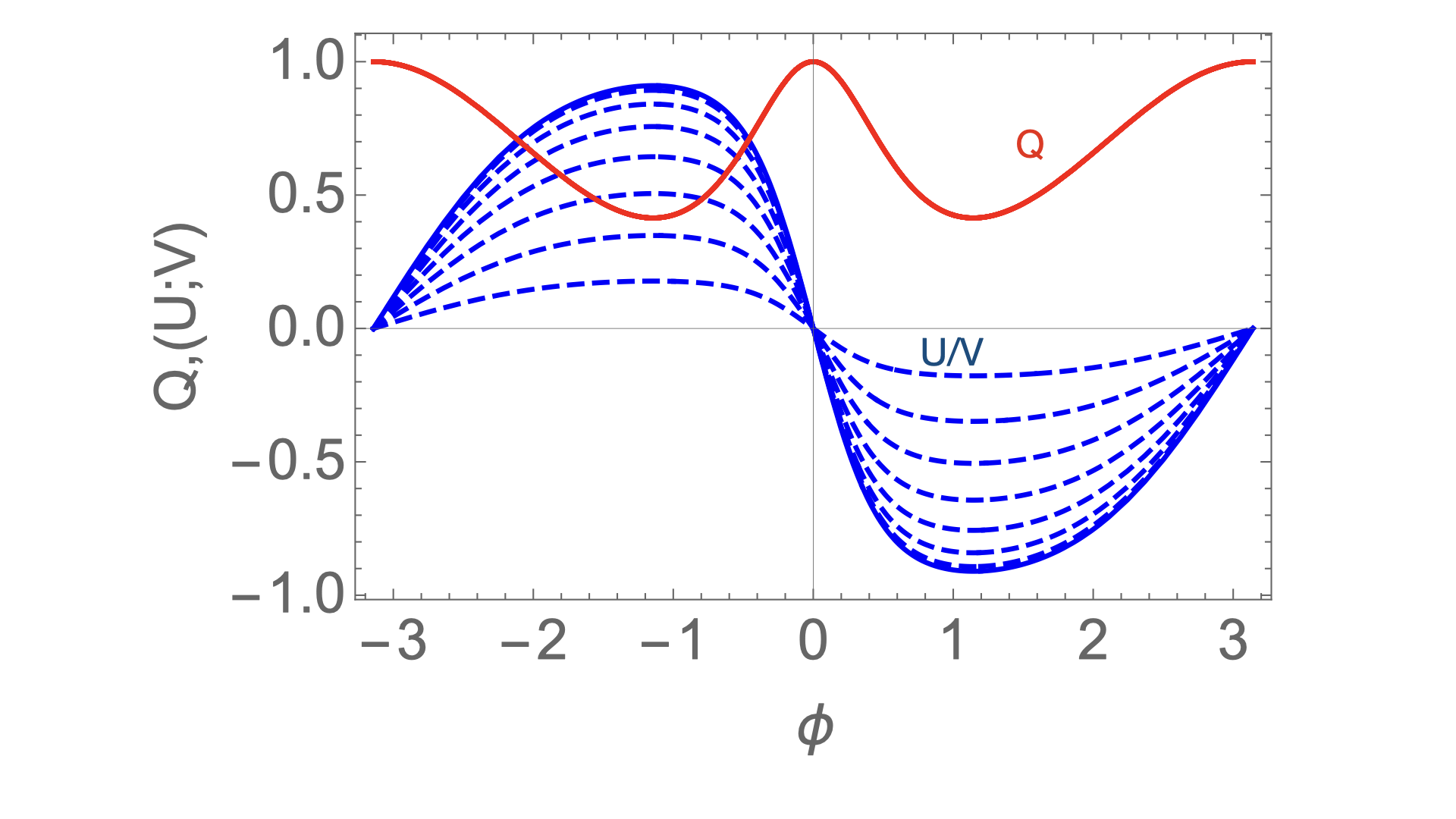
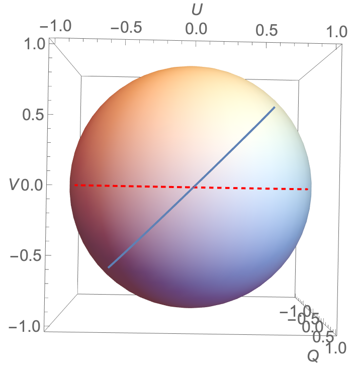
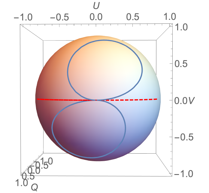
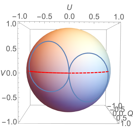
We stress that RVM may not be applicable to magnetar/FRB radio emission (and to Crab pulsar). RVM assumes that global dipole structure of field lines determines local polarization properties of the emitted radiation. In magnetars and FRBs the structure is expected to be highly-non-dipolar, Solar-like (Lyutikov, 2002, 2015, 2021). Another complication may come from the fact that for oblique rotators the plasma density along the line of sight (and hence the retardance at each moment) may be phase-dependent.
6 Discussion
We discuss the properties of polarization transfer in the near wind regions of magnetars, presumed loci of FRBs; magnetospheric model of radio emission from magnetars and FRBs (Lyutikov, 2002; Popov & Postnov, 2013; Lyutikov & Popov, 2020; Lyutikov, 2021) is assumed. We point out the importance of wave propagation in the inner parts of magnetar’s winds. Qualitatively, a phase shift between the X and O components of the order of a wavelength, centimeters, leads to large changes of the polarization properties.
The birefringent pair-symmetric plasma works a wave retarder, periodically converting Stokes into Stokes (in a properly defined frame, where one of the axis is aligned with magnetic field). Unlike the case of conventional Faraday conversion, here Q-U oscillate in phase (since the Q-U separation depends on the coordinate frame chosen).
The model offers explanations for (i) large circular polarization component observed in FRBs, with right-left switching; (ii) large RM, with possible sign changes (if the observed PA change against frequency is less than 1 rad in the observed frequency range); (iii) time-depend variable polarization. Relatively dense and slow wind is needed - the corresponding effect in regular pulsars is small.
The present model offers a way to produce large circular polarization and large RM, both with changing sign in FRB 20190520B (Dai et al., 2022). Relatively dense plasma is required - in regular pulsars this effect is less important that in magnetars (which are expected to produce denser winds). Pulsars clearly do not show such wild polarization behavior. The rotating vector model (Radhakrishnan & Cooke, 1969), that neglects all the propagation effects, does account for many pulsar PA profiles (though there are many exceptions when it’s not: e.g. in Crab). Relation (51) gives the simplest estimate of the PA effect in the wind. The propagation effects are not important in regular pulsars, with the low plasma density and high (the Goldreich & Julian (1969) density is much smaller that what is expected in magnetars (Thompson et al., 2002; Beloborodov & Thompson, 2007)).
The main prediction of the model is that scaling of the PA with frequency may deviate from the conventional RM with . The reverse is not true: the model does allow for scaling, especially at small retardance . There are observational hints, the most interesting analysis is by Price et al. (2019), their Fig. 8. They demonstrate that linear relation is consistent with data.
Most observational works typically assumes a regular RM scaling: in fact, the frequency behavior of polarized components must be fitted independently (e.g. Kumar et al., 2022).
If the system of coordinates is aligned with the projection of the spin axis on the plane of the sky then during propagation through symmetric pair wind the Stokes Q remains constant while U and V experience periodic oscillations. The separation between Q and U depends on the chosen system of coordinates, versus . Since the expected track on the Poincare sphere involves only U-V oscillations, this could be used to determine (to uncertainty) the projection of the pulsar/magnetar spin on the plane of the sky. For example, constant position on the Poincare sphere with may imply that this is a pure Stokes’ Q (alternatively explanation would be that propagation effects are not important while the emitted PA is constant.)
Finally, magnetars show variations of activity on time scales from days to months (Kaspi & Beloborodov, 2017). It is expected that winds are similarly variable. Variations of the density of the wind will lead to medium-to-long time scale variations of the polarization properties.
7 ACKNOWLEDGEMENTS
This work had been supported by NASA grants 80NSSC17K0757 and 80NSSC20K0910, NSF grants 1903332 and 1908590. I would like to thank Vasily Beskin, Andrei Gruzinov, Marcus Lower, Yuri Levin, Yuri Lyubarski, Kiyoshi Masui, Donald Melrose, Alexandre Philippov, Eric Poisson and Louise Willingale for discussions.
8 DATA AVAILABILITY
The data underlying this article will be shared on reasonable request to the corresponding author.
References
- Arons & Barnard (1986) Arons, J., & Barnard, J. J. 1986, ApJ, 302, 120
- Arons & Scharlemann (1979) Arons, J., & Scharlemann, E. T. 1979, ApJ, 231, 854
- Atoyan (1999) Atoyan, A. M. 1999, A&A, 346, L49
- Barnard (1986) Barnard, J. J. 1986, ApJ, 303, 280
- Beloborodov (2013) Beloborodov, A. M. 2013, ApJ, 777, 114
- Beloborodov & Thompson (2007) Beloborodov, A. M., & Thompson, C. 2007, ApJ, 657, 967
- Beskin & Philippov (2012) Beskin, V. S., & Philippov, A. A. 2012, MNRAS, 425, 814
- Born & Wolf (1980) Born, M., & Wolf, E. 1980, Principles of Optics Electromagnetic Theory of Propagation, Interference and Diffraction of Light
- Budden (1952) Budden, K. G. 1952, Proceedings of the Royal Society of London Series A, 215, 215
- Caleb et al. (2019) Caleb, M., van Straten, W., Keane, E. F., Jameson, A., Bailes, M., Barr, E. D., Flynn, C., Ilie, C. D., Petroff, E., Rogers, A., Stappers, B. W., Venkatraman Krishnan, V., & Weltevrede, P. 2019, MNRAS, 487, 1191
- Cheng & Ruderman (1979) Cheng, A. F., & Ruderman, M. A. 1979, ApJ, 229, 348
- Dai et al. (2022) Dai, S., Feng, Y., Yang, Y. P., Zhang, Y. K., Li, D., Niu, C. H., Wang, P., Xue, M. Y., Zhang, B., Burke-Spolaor, S., Law, C. J., Lynch, R. S., Connor, L., Anna-Thomas, R., Zhang, L., Duan, R., Yao, J. M., Tsai, C. W., Zhu, W. W., Cruces, M., Hobbs, G., Miao, C. C., Niu, J. R., Filipovic, M. D., & Zhu, S. Q. 2022, arXiv e-prints, arXiv:2203.08151
- Ginzburg & Syrovatskii (1965) Ginzburg, V. L., & Syrovatskii, S. I. 1965, ARA&A, 3, 297
- Goldreich & Julian (1969) Goldreich, P., & Julian, W. H. 1969, ApJ, 157, 869
- Goldreich & Julian (1970) —. 1970, ApJ, 160, 971
- Gruzinov & Levin (2019) Gruzinov, A., & Levin, Y. 2019, ApJ, 876, 74
- Hankins et al. (2016) Hankins, T. H., Eilek, J. A., & Jones, G. 2016, ApJ, 833, 47
- Hibschman & Arons (2001) Hibschman, J. A., & Arons, J. 2001, ApJ, 560, 871
- Kaspi & Beloborodov (2017) Kaspi, V. M., & Beloborodov, A. M. 2017, ARA&A, 55, 261
- Kazbegi et al. (1991a) Kazbegi, A. Z., Machabeli, G. Z., & Melikidze, G. I. 1991a, MNRAS, 253, 377
- Kazbegi et al. (1991b) Kazbegi, A. Z., Machabeli, G. Z., Melikidze, G. I., & Smirnova, T. V. 1991b, Astrophysics, 34, 234
- Kennel & Coroniti (1984) Kennel, C. F., & Coroniti, F. V. 1984, ApJ, 283, 710
- Kennett & Melrose (1998) Kennett, M., & Melrose, D. 1998, PASA, 15, 211
- Kumar et al. (2022) Kumar, P., Shannon, R. M., Lower, M. E., Deller, A. T., & Prochaska, J. X. 2022, arXiv e-prints, arXiv:2204.10816
- Landau & Lifshitz (1960) Landau, L. D., & Lifshitz, E. M. 1960, Electrodynamics of continuous media (Energy Conversion Management)
- Landau & Lifshitz (1975) —. 1975, The classical theory of fields
- Luo et al. (2020) Luo, Y., Lyutikov, M., Temim, T., & Comisso, L. 2020, ApJ, 896, 147
- Lyutikov (1999) Lyutikov, M. 1999, Journal of Plasma Physics, 62, 65
- Lyutikov (2002) —. 2002, ApJ, 580, L65
- Lyutikov (2007) —. 2007, MNRAS, 381, 1190
- Lyutikov (2013) —. 2013, MNRAS, 431, 2580
- Lyutikov (2015) —. 2015, MNRAS, 447, 1407
- Lyutikov (2021) —. 2021, ApJ, 922, 166
- Lyutikov & Gavriil (2006) Lyutikov, M., & Gavriil, F. P. 2006, MNRAS, 368, 690
- Lyutikov et al. (2012) Lyutikov, M., Otte, N., & McCann, A. 2012, ApJ, 754, 33
- Lyutikov & Popov (2020) Lyutikov, M., & Popov, S. 2020, arXiv e-prints, arXiv:2005.05093
- Masui et al. (2015) Masui, K., Lin, H.-H., Sievers, J., Anderson, C. J., Chang, T.-C., Chen, X., Ganguly, A., Jarvis, M., Kuo, C.-Y., Li, Y.-C., Liao, Y.-W., McLaughlin, M., Pen, U.-L., Peterson, J. B., Roman, A., Timbie, P. T., Voytek, T., & Yadav, J. K. 2015, Nature, 528, 523
- Melrose (1997) Melrose, D. B. 1997, Phys. Rev. E, 56, 3527
- Michel (1969) Michel, F. C. 1969, ApJ, 158, 727
- Michel (1973a) —. 1973a, ApJ, 180, 207
- Michel (1973b) —. 1973b, ApJ, 180, L133
- Michilli et al. (2018) Michilli, D., Seymour, A., Hessels, J. W. T., Spitler, L. G., Gajjar, V., Archibald, A. M., Bower, G. C., Chatterjee, S., Cordes, J. M., Gourdji, K., Heald, G. H., Kaspi, V. M., Law, C. J., Sobey, C., Adams, E. A. K., Bassa, C. G., Bogdanov, S., Brinkman, C., Demorest, P., Fernandez, F., Hellbourg, G., Lazio, T. J. W., Lynch, R. S., Maddox, N., Marcote, B., McLaughlin, M. A., Paragi, Z., Ransom, S. M., Scholz, P., Siemion, A. P. V., Tendulkar, S. P., van Rooy, P., Wharton, R. S., & Whitlow, D. 2018, Nature, 553, 182
- Petroff et al. (2019) Petroff, E., Hessels, J. W. T., & Lorimer, D. R. 2019, A&A Rev., 27, 4
- Petrova & Lyubarskii (2000) Petrova, S. A., & Lyubarskii, Y. E. 2000, A&A, 355, 1168
- Popov & Postnov (2013) Popov, S. B., & Postnov, K. A. 2013, arXiv e-prints, arXiv:1307.4924
- Price et al. (2019) Price, D. C., Foster, G., Geyer, M., van Straten, W., Gajjar, V., Hellbourg, G., Karastergiou, A., Keane, E. F., Siemion, A. P. V., Arcavi, I., Bhat, R., Caleb, M., Chang, S. W., Croft, S., DeBoer, D., de Pater, I., Drew, J., Enriquez, J. E., Farah, W., Gizani, N., Green, J. A., Isaacson, H., Hickish, J., Jameson, A., Lebofsky, M., MacMahon, D. H. E., Möller, A., Onken, C. A., Petroff, E., Werthimer, D., Wolf, C., Worden, S. P., & Zhang, Y. G. 2019, MNRAS, 486, 3636
- Radhakrishnan & Cooke (1969) Radhakrishnan, V., & Cooke, D. J. 1969, Astrophys. Lett., 3, 225
- Ravi et al. (2016) Ravi, V., Shannon, R. M., Bailes, M., Bannister, K., Bhandari, S., Bhat, N. D. R., Burke-Spolaor, S., Caleb, M., Flynn, C., Jameson, A., Johnston, S., Keane, E. F., Kerr, M., Tiburzi, C., Tuntsov, A. V., & Vedantham, H. K. 2016, Science, 354, 1249
- Ruderman & Sutherland (1975) Ruderman, M. A., & Sutherland, P. G. 1975, ApJ, 196, 51
- Sazonov (1969) Sazonov, V. N. 1969, Soviet Ast., 13, 396
- Shklovskii (1977) Shklovskii, I. S. 1977, Soviet Ast., 21, 371
- Sincell & Krolik (1992) Sincell, M. W., & Krolik, J. H. 1992, ApJ, 395, 553
- Thompson et al. (1994) Thompson, C., Blandford, R. D., Evans, C. R., & Phinney, E. S. 1994, ApJ, 422, 304
- Thompson et al. (2002) Thompson, C., Lyutikov, M., & Kulkarni, S. R. 2002, ApJ, 574, 332
- Timokhin (2010) Timokhin, A. N. 2010, MNRAS, 408, 2092
- Vedantham & Ravi (2019) Vedantham, H. K., & Ravi, V. 2019, MNRAS, 485, L78
- Wang et al. (2010) Wang, C., Lai, D., & Han, J. 2010, MNRAS, 403, 569
- Wilson & Rees (1978) Wilson, D. B., & Rees, M. J. 1978, MNRAS, 185, 297
- Zheleznyakov (1996) Zheleznyakov, V. V. 1996, Radiation in Astrophysical Plasmas, Vol. 204