Millisecond burst extractions from synchrotrons using RF phase displacement acceleration
Abstract
FLASH radiation therapy calls for the delivery of fast bursted spills of particles with dose delivery times of the order of milliseconds. The requirements overlap with fundamental physics experimental requests that are being studied at CERN, albeit at very different energy scales. In this contribution, a scheme for extracting millisecond bursts from synchrotrons is explored by controlling a third-integer resonant and chromatic extraction with RF phase displacement acceleration. The scheme would be implementable in existing medical and experimental synchrotron facilities. Using a model of the CERN Proton Synchrotron, both single-burst and multi-burst extractions are simulated. Results show that 80 - 90% of the total beam intensity is extracted in a single burst of 40 - 60 ms. This would correspond to a 10 ms burst in a typical medical synchrotron, namely the one outlined in the Proton Ion Medical Machine Study. A set of 3 consecutive bursts of 30 ms was simulated in the Proton Synchrotron with optimised machine parameters.
keywords:
FLASH Therapy , Synchrotron , Resonant Slow Extraction , RF Phase Displacement[inst1]organization=CERN,city=Geneva, postcode=1211, country=Switzerland
[inst2]organization=University of Oxford,addressline=Keble Road, city=Oxford, postcode=OX1 3RH, country=UK
1 Introduction
Within the Physics Beyond Colliders (PBC) Study Group at CERN, novel methods of resonant slow extraction from synchrotrons are being explored to satisfy the requirements of future fundamental physics experiments. Recent studies for Enhanced NeUtrino BEams from kaon Tagging (ENUBET) investigated the extraction of millisecond bursts of protons from the CERN Super Proton Synchrotron (SPS) by pulsing the main quadrupole circuit [1]. Furthermore, a novel radiation oncology therapy known as FLASH [2] has awoken interest in the delivery of fast bursted spills of particles in the medical community. FLASH is an ultra-high dose rate irradiation technique that relies on total dose delivery times of the order of milliseconds, often with RF time structure of several MHz. As a consequence, ongoing studies [3] are evaluating the potential of different accelerator types as candidates for delivery of FLASH therapy. In this paper, an acceleration scheme known as radio frequency (RF) phase displacement [4] is explored to control the bursting of a resonant third-integer extraction. The same mechanism could also be exploited to feed other resonances like the half-integer, which has been employed in the SPS for fast resonant extractions [5] in the past. The flexibility of digital low-level RF control systems in synchrotrons makes this technique easy to implement and optimise. Additionally, no ramping of magnetic elements is required, avoiding magnet ramp rate limits and optics perturbations that could render certain loss reduction techniques such as crystal shadowing [6] or octupole folding [7] inefficient. RF phase displacement also has the benefit of extracting at constant momentum, while quadrupole sweep techniques produce a time-varying momentum profile. For these reasons, the scheme could be attractive for the exploitation of existing experimental and medical synchrotrons as burst extraction facilities.
RF phase displacement was originally used in the 1960s as a beam acceleration technique in the CERN Intersecting Storage Rings [8]. In 1999, the Proton-Ion Medical Machine Study (PIMMS) [9] considered RF phase displacement as a potential mechanism for slow-extraction spills of around 1 s, but it was ultimately discarded due to the strong modulation it introduced at the repetition period of the sweeping of the RF frequency [10]. For the burst extraction application, the method’s initial weakness is turned into a strength by maximizing the modulation to provide short discrete pulses of particles. Here we study the transverse and longitudinal beam dynamics of the method via simulation; we propose both single-burst and multi-burst schemes and assess their limits as a burst extraction technique. The CERN Proton Synchrotron is employed as a case study because of its availability for beam tests and its flexible RF equipment that will allow experimental studies in the future. Nevertheless, the procedure can be generalised to any synchrotron and a comparison with SPS and PIMMS parameters is also qualitatively addressed.
2 RF Burst Extraction Concept
2.1 Simulation scheme
A simple model of the synchrotron was implemented in a code called henontrack [11], which was exploited to perform tracking simulations. The lattice was reduced to four elements: an effective sextupole, an effective RF cavity, a linear transport matrix and an extraction septum. Particle coordinates were represented in a 4D trace space corresponding to normalised horizontal amplitude, normalised horizontal angle, phase offset and relative momentum deviation, respectively.
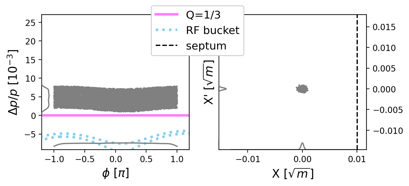
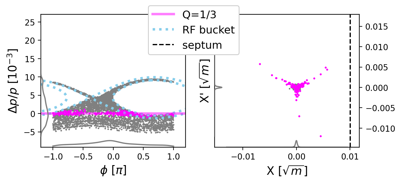
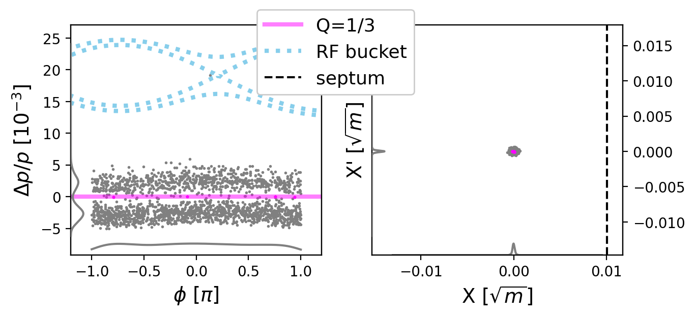
The RF phase displacement scheme is shown in Fig. 1 and can be summarised as follows:
-
1.
An ensemble of particles is generated with a horizontal transverse Gaussian distribution of geometric RMS emittance and a uniform longitudinal distribution of momentum spread (Fig. 1(a)).
-
2.
The RF system is programmed to follow a linear frequency ramp that sweeps empty buckets through the stack of particles in longitudinal phase space (Fig. 1(b)).
-
3.
As particles are kicked by the RF cavity they are accelerated, which results in a change in their tune via chromaticity.
-
4.
Particles with resonant tune gain amplitude until they jump over the septum and are extracted.
-
5.
After the sweep, some particles may remain in the machine (Fig. 1(c)).
-
6.
Steps 2-4 are repeated times to provide bursts.
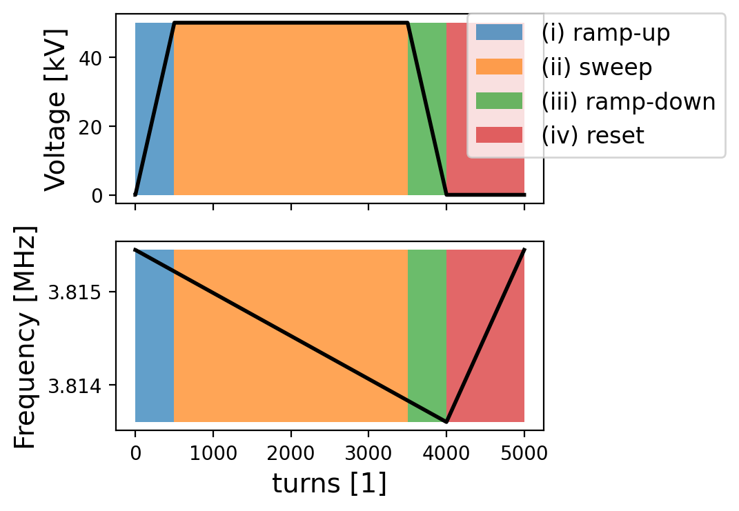
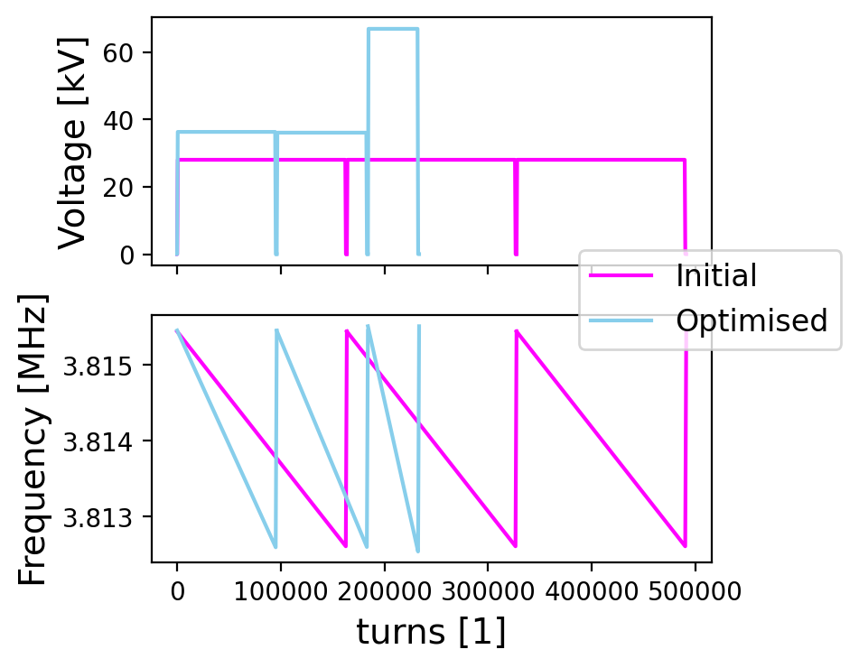
An example of the voltage and frequency programs employed in simulation is shown in Fig. 2 . For all simulations, the voltage was ramped (up or down) in 500 turns and the frequency was reset to its initial value in 1000 turns. To produce bursts, of these programs were concatenated.
2.2 Relevant parameters
When the RF frequency is swept through the circulating beam, the distribution of experiences both an average coherent displacement and a blow-up with root mean square increase in spread . The effect on the distribution can be derived analytically [12, 13] and expressed as,
where , is the synchronous phase, is the bucket area factor and is the stationary bucket area in () space given by,
where is the electron charge, is the RF voltage, is the relativistic speed factor, is the beam energy, is the RF harmonic number and is the slip factor. The expressions can be normalised to the initial momentum spread of the beam to obtain,
| (1) |
where is the ratio between the stationary bucket area and the phase space area of the coasting beam. This relationship provides an intuitive interpretation: to push a fraction of the beam into the resonance, the sweeping bucket must have approximately a factor of the stack area. However, one must additionally account for the blow-up contribution, which makes the relationship less straightforward. Furthermore, and vary slightly (1% for the PS) during the sweep as changes but stays fixed, which makes correct only for the average parameters. Both of these effects were included in the numerical tracking. On the other hand, the variation of as a function of was not included (since linear longitudinal transport was assumed), but the change is small ( 1% for the PS) if the machine is operated far from transition energy. For a large number of sweeps, the variation in could produce a noticeable perturbation [9].
In practice will have a maximum value for a given , since the RF frequency cannot be ramped arbitrarily fast. The ramp rate is given by,
, where is the RF frequency and is the proportionality constant between and ramp rate in physical units. This establishes a maximum given by,
, where is the maximum RF ramp rate. This directly sets a minimum .
2.3 Longitudinal and transverse transit times
In the longitudinal plane, a timescale for each burst can be estimated by ignoring dynamic effects; simply the time needed to move the entire bucket area across the same amount of area in the stack. In other words, the (virtual) synchronous particle inside the sweeping bucket must travel a distance , where is the bucket height. Ultimately, numerical simulations are needed to account for dynamic effects. The timescale (in number of turns) is given by,
| (2) |
where is the bucket height factor [13]. The first term captures the dependence on and the second term provides the time needed for the synchronous particle to cross the entire stack at a given voltage. The latter can easily be compared across machines by setting to the maximum voltage , as shown in Table 1 by .
In the transverse plane, particles take a finite amount of time to gain amplitude and jump over the extraction septum. This transit time varies between particles and it is dependent on their initial coordinates when entering the resonant region and their tune speed [9]. Nevertheless, a characteristic timescale (in number of turns) can be obtained [14] and expressed as,
where is the virtual sextupole strength of the machine [9]. Dynamic effects faster than will limit the extraction process, e.g. certain particles could cross the resonant region too fast to be extracted. In RF phase displacement the coherent kicks from the RF could make the tune speed of certain particles too large, transporting them back to a stable tune before they can reach the septum. Numerical simulations quantify the severity of this effect.
| Parameter | PS, | PIMMS | SPS |
|---|---|---|---|
| h=8 (16) | |||
| Kinetic E. [GeV] | 24 | 0.25 | 400 |
| [mm.mrad] | 0.059 | 0.67 | 0.0018 |
| T [s] | 2.1 | 0.4 | 23 |
| h [] | 8 (16) | 1 | 4620 |
| [kV] | 200 | 4 | 10000 |
| [] | 0.024 | -0.37 | 0.0018 |
| S [m-1/2] | 77 | 30 | 170 |
| [kHz/ms] | 0.37 (0.74) | 18 | 0.40 |
| [] | 6 | 4 | 3 |
| [turns] | 430 | 330 | 350 |
| [] | 1.1 (0.78) | 1.3 | 0.58 |
| [turns] | 720 | 450 | 120 |
Table 1 summarises the relevant parameters for the PS (both for and ), the SPS and a PIMMS-like synchrotron. The PIMMS-like machine and the PS () differ considerably in nominal parameters, but the normalised parameters , and are within 40% of each other. Therefore, we expect results in the PS to be indicative of the PIMMS-like machines, as long as they are expressed in terms of unitless parameters. Due in part to its high RF harmonic number, the SPS parameters differ from the PS parameters.
3 Simulation Results and Discussion
3.1 Single burst extraction
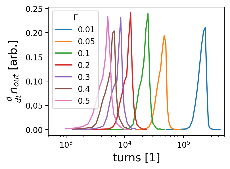
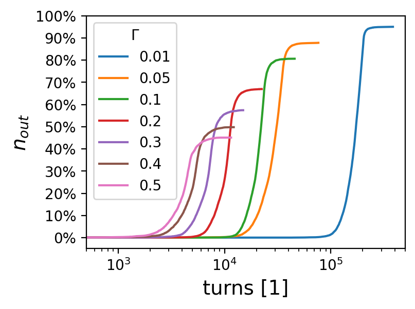
Single burst simulations were performed for a fixed voltage , and fixed harmonic (as it provided a larger ), whilst scanning . The instantaneous and cumulative intensities of the extracted spills are shown in Fig. 3. As predicted by Eq. 2, the larger the , the shorter the bursts (shorter ), but fewer particles are extracted as predicted by Eq. 1 because of the smaller .
Simulations were repeated with identical and , but with . This changes and while keeping all other parameters constant. Fig. 4 shows the percentage of extracted particles as a function of . In an idealised situation without blow-up or finite extraction time, the simulated data points would lie on the line. At low blow-up effects drive a substantial number of particles into or away from the resonance due to the large . For all settings, a certain number of particles experience large changes in tune per turn. This fast change in tune has the potential to increase the transverse emittance of the extracted beam [15] and some particles even cross the resonance region too quickly to be extracted, becoming non-resonant again and remaining in the machine. This reduces the efficiency of the scheme but could be combated by shortening , as particles would then need less turns to reach the septum. These effects are included in all simulation results. Nevertheless, the simulated dependence of remains approximately a linear trend (dashed lines), and especially for , where the blow-up effects are smaller due to the smaller .
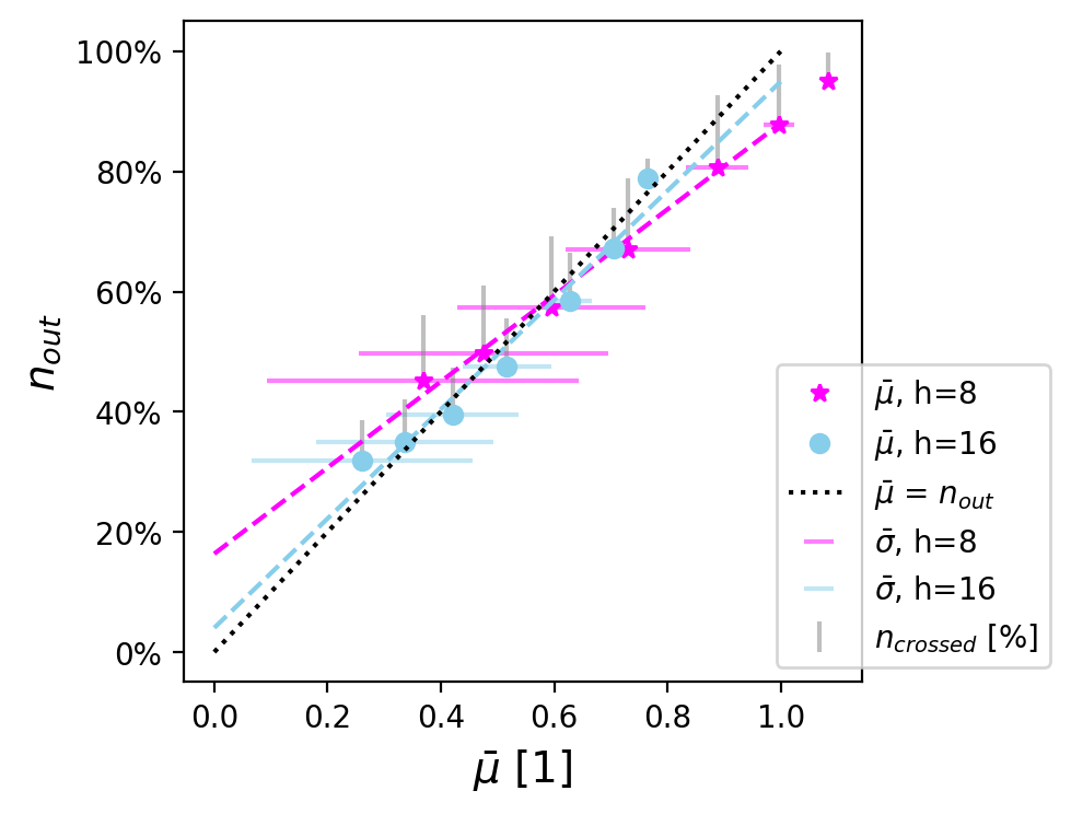
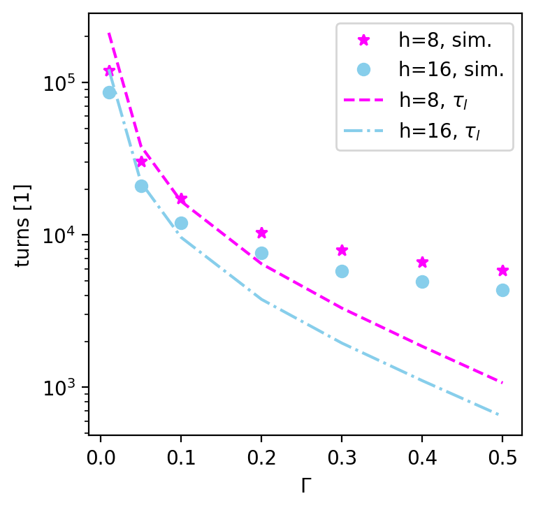
Fig. 5 shows the extraction time as a function of . The extraction time was computed as the number of turns required to extract from 1% to 99% of the total extracted intensity, i.e. including only the central 98%. This metric was chosen to stop outliers from dominating the calculation, as they can dramatically increase the total extraction time (by a factor 2 or more). is within a factor 2 of the simulation output for all the data points. However, dynamic effects clearly play an important role at large .
3.2 Multiple burst extraction
One can exploit the knowledge acquired in the previous subsection to generalise the scheme to multiple bursts, which is highly relevant for FLASH therapy. For a given set of machine parameters, one can estimate an initial guess for such that the extraction has bursts with turns per burst by solving the system of equations,
| (3) |
as shown in Figs. 6 and 7. Such an estimate does not account for blow-up and finite transit time and would have to be further studied and optimised. The scheme would be limited by and . The latter could be reduced with higher or larger .
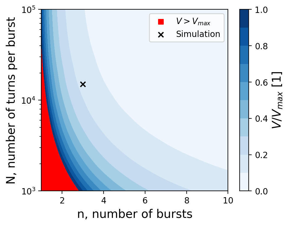
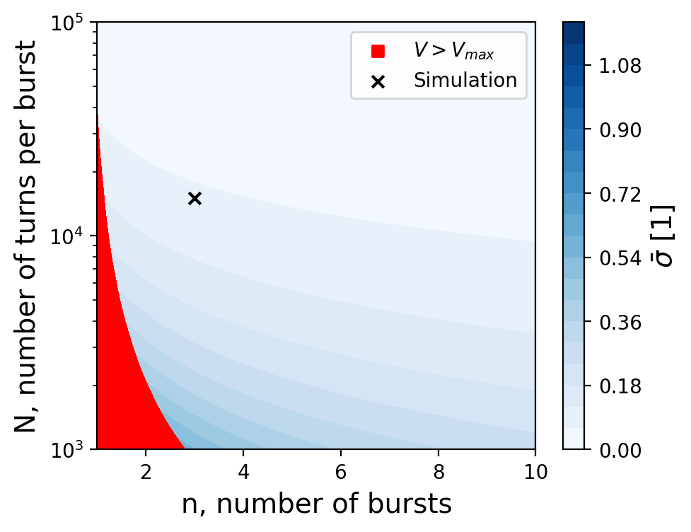
Fig. 6 shows the required voltage for different combinations of and , which establishes the forbidden region due to voltage limitations. Furthermore, larger leads to larger , which may complicate operation and optimisation of consecutive bursts. Figure 7 shows for different combinations of and .
To test the validity of the approximations made in Figs. 6 and 7 tracking simulations were carried out for the specific combination of and (chosen as an example). The settings from the contour plots were used as initial conditions for an optimisation procedure employing the algorithm Py-BOBYQA [16]. In order to account for , the target was set to 90% of the total intensity. This lead to an initial guess of 28 kV, and an expected blow-up of . The optimiser was allowed to vary and for each sweep independently. The cost function was specified as,
where is the sweep number and was normalised to 90% of the total intensity. Fig. 8 shows the instantaneous intensity profiles for both the initial guess and the optimised settings found by the optimiser: kV, . Fig. 9 shows the voltage and frequency programs for both schemes.
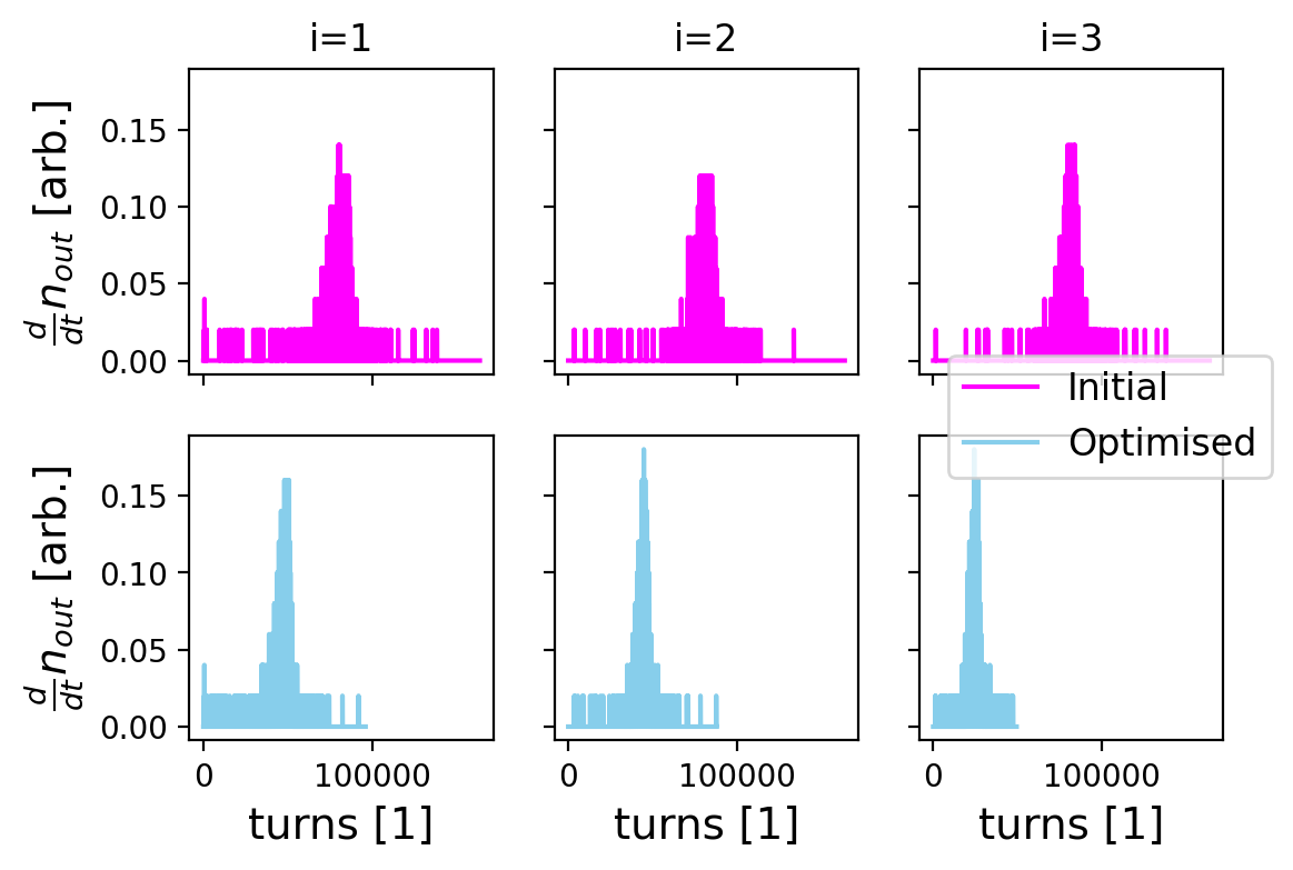
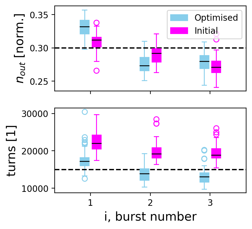
The simulation was executed fifty times with particles to test the robustness of the scheme and the results are shown in Fig. 10. The initial setting produced longer extraction times than the target for all bursts, which is consistent with Fig. 5; consistently underestimates the extraction time for . The optimised settings brought the extraction time down reducing the average relative error in N from 37% to 12%. The average relative error in increased from 5% to 9%, but since the cost function weighs both errors equally this solution is preferred. A different cost function could be more suitable depending on the specific operational requirements. Furthermore, the solution to this cost function is likely to be non-unique and further optimisation could be possible (e.g. by including more sophisticated control on the voltage and frequency programs). This particular implementation is a simple showcase of the flexibility of the scheme.
4 Conclusion and Outlook
RF phase displacement acceleration was exploited to provide short bursts of particles from a synchrotron in a scheme that could be attractive for exploitation at existing experimental and medical synchrotrons, with FLASH therapy in mind. Employing a simplified model of the PS, it was shown that 80 - 90% of the total beam intensity could be extracted in a single burst of 20000 - 30000 turns. This corresponds to 40 - 60 ms in the PS and 8 - 12 ms in PIMMS-like machines. Moreover, a few basic parameters were computed to characterise the extraction scheme. The parameters were informative, but simulation showed that dynamic effects ultimately played an important role in the extracted intensity and extraction time. A 3-burst scheme with 15000 turns per burst could be realised in a simulation of the PS with optimised machine parameters. Future work will demonstrate the implementation of the extraction technique with measurements at the PS, whilst exploiting sophisticated optimisation and control tools.
5 Acknowledgements
This work was supported by the Physics Beyond Colliders (PBC) Study Group. The authors thank PBC for their support. The same gratitude is extended to H. Damerau and M. Vadai from the CERN SY-RF team for the enriching discussions on RF systems. The first author would also like to thank the CERN Accelerator Beam Transfer group for supporting the attendance to the FLASH Radiotherapy & Particle Therapy conference in 2021.
References
- [1] M. Pari, Study and development of SPS slow extraction schemes and focusing of secondary particles for the ENUBET monitored neutrino beam, Ph.D. thesis, Università degli studi di Padova (2020).
- [2] M. C. Vozenin, P. De Fornel, K. Petersson, V. Favaudon, M. Jaccard, J. F. Germond, B. Petit, et al., The advantage of FLASH radiotherapy confirmed in mini-pig and cat-cancer patients, Clinical Cancer Research (2019) 35–42.
- [3] H. Jolly, S. amd Owen, M. Schippers, C. Welsch, Technical challenges for FLASH proton therapy, Physica Medica 78 (2020) 71–82.
- [4] L. W. Jones, C. H. Pruett, K. Symon, K. Terwilliger, Comparison of experimental results with the theory of radio-frequency acceleration processes in FFAG accelerators, Proc. International Conference on High-Energy Accelerators and Instrumentation (1959) 58–70.
- [5] K. H. Kissler, J. Riche, W. Scandale, G. Schroeder, Fast resonant extraction from the CERN SPS, 8th Particle Accelerator Conference (1979).
-
[6]
F. M. Velotti, L. S. Esposito, M. A. Fraser, V. Kain, S. Gilardoni, B. Goddard,
M. Pari, J. Prieto, R. Rossi, W. Scandale, L. S. Stoel, F. Galluccio,
M. Garattini, Y. Gavrikov,
Septum
shadowing by means of a bent crystal to reduce slow extraction beam loss,
Phys. Rev. Accel. Beams 22 (2019) 093502.
doi:10.1103/PhysRevAccelBeams.22.093502.
URL https://link.aps.org/doi/10.1103/PhysRevAccelBeams.22.093502 -
[7]
M. A. Fraser, B. Goddard, V. Kain, M. Pari, F. M. Velotti, L. S. Stoel,
M. Benedikt,
Demonstration
of slow extraction loss reduction with the application of octupoles at the
cern super proton synchrotron, Phys. Rev. Accel. Beams 22 (2019) 123501.
doi:10.1103/PhysRevAccelBeams.22.123501.
URL https://link.aps.org/doi/10.1103/PhysRevAccelBeams.22.123501 - [8] K. N. Henrichsen, M. J. de Jonge, Acceleration by phase displacement in the ISR, 9th International Conference on High Energy Accelerators (1974) 390–393.
- [9] L. Badano, M. Benedikt, P. J. Bryant, M. Crescenti, P. Holy, A. T. Maier, M. Pullia, S. Rossi, P. Knaus, Proton-Ion Medical Machine Study (PIMMS), 1, CERN-TERA Foundation-MedAustron Oncology-2000 Collaboration (1999).
- [10] U. Dorda, A. Wastl, H. Schonauer, M. Benedikt, Simulation studies of longitudinal RF-noise and phase-displacement acceleration as driving mechanism for the MedAustron synchrotron slow extraction, Proceedings of 4th International Particle Accelerator Conference (2013).
- [11] P. A. Arrutia Sota, Henontrack, https://gitlab.cern.ch/parrutia/henontrack (2022).
- [12] E. W. Messerschmid, Scattering of particles by phase displacement acceleration in storage rings, CERN Archives (1973).
- [13] S. Lee, Accelerator Physics, 4th edition, World Scientific, 2019.
- [14] K. Cornelis, Momentum cleaning in the LHC with resonant extraction, LHC Project Note 176 (1998).
- [15] J. P. Prieto, M. A. Fraser, B. Goddard, V. Kain, L. S. Stoel, F. M. Velotti, Beam dynamics simulations of the effect of power converter ripple on slow extraction at the CERN SPS, Proceedings of the 9th International Particle Accelerator Conference (2019).
- [16] C. Cartis, J. Fiala, B. Marteau, L. Roberts, Improving the flexibility and robustness of model-based derivative-free optimization solvers, ACM Transactions on Mathematical Software (2019).