Omm \NewDocumentCommand\unitOm
![[Uncaptioned image]](/html/2203.07964/assets/IMCC.png) https://muoncollider.web.cern.ch
https://muoncollider.web.cern.ch
Simulated Detector Performance at the Muon Collider
Submitted to the Proceedings of the US Community Study
on the Future of Particle Physics (Snowmass 2021)
This is one of the five reports submitted to Snowmass by the muon colliders community at large. The reports’ preparation effort has been coordinated by the International Muon Collider Collaboration. Authors and Signatories have been collected with a
subscription page, and are defined as follows:
•
An “Author” contributed to the results documented in the report in any form, including e.g. by participating to the discussions of the community meetings and sending comments on the draft, or plans to contribute to the future work.
•
A “Signatory” expresses support to the efforts described in the report and endorses the Collaboration plans.
Abstract
In this paper we report on the current status of studies on the expected performance for a detector designed to operate in a muon collider environment. Beam-induced backgrounds (BIB) represent the main challenge in the design of the detector and the event reconstruction algorithms. The current detector design aims to show that satisfactory performance can be achieved, while further optimizations are expected to significantly improve the overall performance. We present the characterization of the expected beam-induced background, describe the detector design and software used for detailed event simulations taking into account BIB effects. The expected performance of charged-particle reconstruction, jets, electrons, photons and muons is discussed, including an initial study on heavy-flavor jet tagging. A simple method to measure the delivered luminosity is also described. Overall, the proposed design and reconstruction algorithms can successfully reconstruct the high transverse-momentum objects needed to carry out a broad physics program.
Executive Summary
Despite the success of the Standard Model (SM) of particle physics, several observations point to the existence of physics beyond what is currently known. Theoretical explanations of such phenomena most probably require new states or forces that manifest at energies higher than what is currently accessible at world leading facilities. The lack of a firm indication of the exact energy scale of those phenomena further motivates an energy frontier research program capable of reaching to the highest possible energy. In the landscape of possible future energy-frontier accelerators, a circular collider, also referred to simply as muon collider, is a particularly attractive option for the future of energy frontier exploration. Such a machine has the potential to deliver a vast physics program [1] in a relatively compact accelerator complex.
The aim of this paper is to describe the expected performance of a multi-purpose Muon Collider Detector (MCD) designed to reconstruct the products of a muon-muon collisions with high accuracy. Several operating center-of-mass energies are possible for the considered machine; in this paper a center-of-mass energy of TeV is explored.
One of the biggest challenges for a MCD is to successfully disentangle the products of the collisions from an intense beam-induced background (BIB) coming primarily from secondary and tertiary interactions of the muon decay products. For this reason an essential part of the Machine Detector Interface (MDI) at a Muon Collider is a pair of tungsten nozzles cladded with borated polyethylene, which reduce the rate and energy of BIB particles that reach the detector by several orders of magnitude. The nozzles limit the maximum angular acceptance of the MCD to about from the beamline axis.
The MCD design presented in this paper follows the classical cylindrical layout typical for multipurpose detectors of symmetric collisions. It consists of a silicon-based Vertex Detector, with innermost barrel layer at mm from the beamline, followed by silicon-based Inner and Outer Trackers. High granularity electromagnetic and hadronic calorimeters and an outer muon spectrometer complement the main elements of the detector.
A detailed GEANT4 based simulation package is used to simulate the response of the detector. A fast digitization and detailed reconstruction algorithms were developed to study the expected performance of the MCD in the event reconstruction. The BIB is overlaid to the process of interest.
Three approaches are studied for track reconstruction at the MCD: a Conformal Tracking (CT) algorithm developed for the clean environment of the electron-positron colliders and supplemented with either a Region of Interest approach or a filter based on double pixel layers in the innermost layers of the detector, and a Combinatorial Kalman Filter (CKF) algorithm developed for the busy environment of hadron colliders. The results show a robust track reconstruction for charged particles with the momentum above GeV throughout the detector acceptance, with the potential for extending towards softer particles.
Jets are reconstructed using a particle-flow approach and a -based clustering. An energy calibration is derived and applied throughout the studies. The performance is evaluated on samples of light, and jets, resulting in a reconstruction efficiency ranging from 82% at GeV to 95% at higher with sub-percent fake rate in the region . The jet energy resolution ranges from about 50% to about , depending on . The resulting di-jet invariant mass resolution allows good separation between hadronically-decaying Higgs and bosons.
A simple heavy-flavor tagging based on finding a displaced-vertex yields a jet identification efficiency ranging from 50% to 80%, depending on , with a mis-tag rate of about (20%) for light (-)jets. It is expected that more advanced algorithms would be able to perform significantly better.
Prototypes of electron and photon reconstruction algorithms able to cope with BIBs have been developed, yielding a successful reconstruction of high- electrons and photons with relatively small loss of efficiency and energy resolution. Muon reconstruction is performed by combining a stand-alone track reconstructed in the muon system and a track reconstructed in the tracker. BIBs mostly affect the forward endcap region. Filtering hits based on their properties as well as based on standalone muon tracks allows for negligible impact of BIB in the performance of muon reconstruction. Reconstruction of other high-\pT objects, as leptons, is still in progress, but it is expected to pose challenges similar to the ones that have been already solved for track and jet reconstruction as well as heavy-flavor jets identification.
The precise determination of the delivered luminosity is of crucial importance for the planned physics program. A method based on Bhabha scattering measurement shows that a statistical precision of about can be achieved for the integrated luminosity delivered per year of data-taking.
In conclusion, this manuscript uses detailed simulation of a proposed Muon Collider detector that satisfies the basic requirements of reconstructing high- objects needed to deliver an ambitious physics program. The effects of BIB is taken into account, showing that its impact can be successfully mitigated.
1 Introduction
The Standard Model (SM) of particle physics has been an extremely successful theory to describe measurements at the energy frontier. In the last decades, a vast physics programs at the energy frontier has produced discoveries that led to the current incarnation of the Standard Model (SM) theory and stress-tested it with precision measurements. Nevertheless, observations, as well as theoretical motivations, unambiguously point to physics phenomena Beyond the Standard Model (BSM). Theoretical explanations of such phenomena almost always require new states or forces that manifest at energies higher than what currently accessible at world leading facilities. Despite the lack of a clear energy target that guarantees with certainty a discovery, multiple indirect indications point to energy scales of several TeV as the most likely energy regime where BSM phenomena would manifest. It is therefore of paramount importance to develop a physics program for the energy frontier that allows us to explore such an energy regime in the future, possibly with the ability of adapting the target energy depending on future insights from accelerator and non-accelerator based experiments.
In the landscape of possible future energy-frontier accelerators [2], a circular collider, also referred to simply as muon collider, is a particularly attractive option for the future of energy frontier exploration [3]. Such a machine has the potential to deliver a vast physics program [1, 4, 5, 6, 7, 8, 9, 10, 11, 12, 13, 14, 15, 16, 17, 18, 19, 20, 21, 22, 23, 24, 25, 26, 27, 28, 29, 30, 31, 32, 33, 34, 35, 36, 37, 38, 39, 40] in a relatively compact accelerator complex [41]. Such an option has been studied in the past [42, 43, 44, 45, 46, 47, 48, 49], and it sparked renewed interest thanks to advances in accelerator technology as well as given the current needs of high-energy exploration of the field.
The aim of this paper is to describe the expected performance of a multi-purpose muon collider detector (MCD). The study focuses on the reconstruction algorithms and performance of high- objects that will be used needed for a successful physics program. The results are built upon and significantly extend the ones reported in Ref. [50]. The current design aims at showing that satisfactory performance can be achieved in a muon collider environment. Further optimization of the detector design and reconstruction algorithms are expected to significantly improve the performance of a MCD and will be subject of future work.
Several operating center-of-mass energies are possible for a future muon collider [41]. In this paper, unless otherwise noted, a center-of-mass energy of TeV is assumed. Table 1 reports additional accelerator parameters that have been assumed for the simulations used for the results presented in this manuscript. Most of the results presented in this manuscript do not simulate the spread of collisions in the transverse and longitudinal directions, unless otherwise stated; it is expected that this has a minor impact on the performance, and it is discussed explicitly when relevant.
| Parameter | Symbol | Value |
|---|---|---|
| Center-of-mass energy | TeV | |
| Muons per bunch | ||
| Normalised transverse emittance | 25 m rad | |
| Normalised longitudinal emittance | 7.5 MeV m | |
| IP relative energy spread | 0.1 % | |
| IP beta function | 1 cm | |
| IP transverse beam size | 6 m | |
| IP longitudinal beam size | 10 mm |
One of the biggest challenges for a MCD is to successfully disentangle the products of the collisions from an intense beam-induced background (BIB) coming primarily from secondary and tertiary interactions of the muon decay products [51, 52, 53]. Section 2 summarizes the main characteristics expected for such a background and also includes a discussion on the expected background composition for higher center-of-mass energy muon colliders.
BIB has a big influence on the detector design, which is summarised in Section 3. The technical challenges for the MCD and the most promising technologies for fulfilling the physics requirements of the detector are described in a separate manuscript [54], which also covers the readout and trigger schema.
Results in this manuscript are obtained using detailed simulations of the MCD based on a Geant4 [55] framework. The software setup is described in Section 4. All simulations, unless otherwise stated, include overlaying on top of the desired collision the model of BIB described in Section 2.
Sections 5, 6, 7 and 8 describe the reconstruction algorithms and expected performance for the basic objects needed to carry a comprehensive physics program. Reconstruction of other objects, as leptons or missing momentum, is still in progress, but it is expected to pose challenges similar to the ones that have been already solved. A method for measuring the delivered luminosity with high accuracy is described in Section 9.
2 Beam-Induced Background characterization
The unstable nature of muons (lifetime \qty2.2 µ at rest) makes the beam-induced background (BIB) a much more challenging issue at a Muon Collider than it is at facilities that use stable-particle beams. In fact, muons per bunch in a \qty750GeV muon beam lead to about muon decays per meter. Interactions of the decay products with the accelerator lattice produce even larger amounts of particles that eventually reach the detector, making the reconstruction of clean collision events nearly impossible without dedicated BIB mitigation. A discussion of the expected radiation levels due to BIB can be found in Ref. [54]. For this reason an essential part of the Machine Detector Interface (MDI) at a Muon Collider is a pair of tungsten (W) nozzles cladded with borated polyethylene (BCH), which reduce the rate and energy of BIB particles reaching the detector by several orders of magnitude.
A dedicated design of the MDI has been developed by MAP collaboration [52] using the MARS15 software [56] to simulate muon decays within \qty±200 from the interaction point (IP) in a collider ring with the parameters summarised in Table 1. The exact shape and positioning of the nozzles was optimised specifically for the \qty1.5TeV case, including the \qty10° opening angle and \qty12\centi distance between the tips of the nozzles, as shown in Fig. 1. The same approach has been adopted by the Muon Collider collaboration based on the FLUKA simulation software to characterize BIB at higher center-of-mass energies and to study other MDI designs.
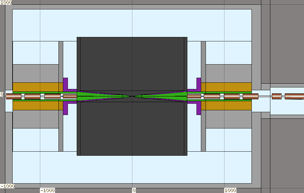
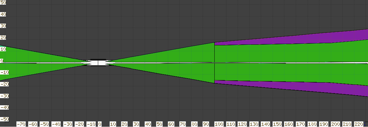
In order to include the effects of the BIB on detector performance the particles induced by the muon decays are collected at the outer surface of the MDI and before entering the detector volume, which is represented by a black box on Fig. 1. This allows to later simulate their interaction with the detector together with particles from the collision. Thus, BIB sample in this article refers to the collection of particles originating from the muon decays before any interaction with the detector material.
2.1 BIB properties at 1.5 TeV
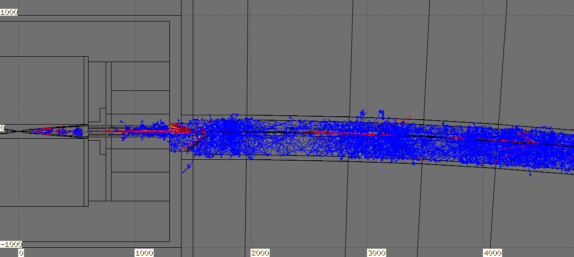
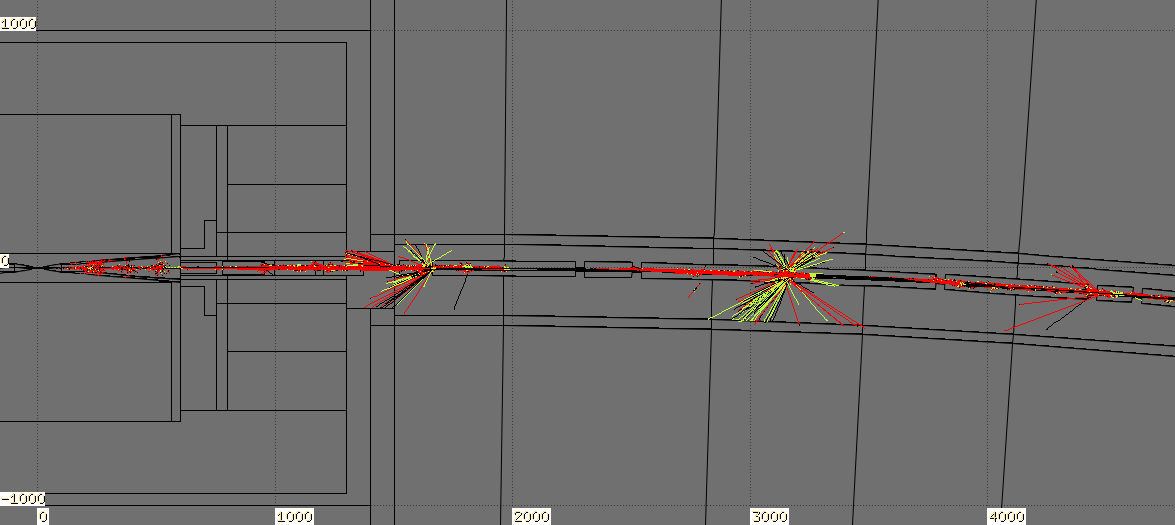
The exact BIB sample used for detector-performance studies at \qty1.5TeV presented in this paper has been produced in MARS15 software, because the FLUKA-based workflow was not fully validated at that time. Yet FLUKA interface is used for visualisation of the accelerator geometry and BIB trajectories in the MDI region thanks to its advanced graphical capabilities. An example of simulated particle decays and their interaction with the accelerator lattice is shown in Fig. 2, demonstrating multiple points along the beamline where BIB particles originate from.


BIB particles at a Muon Collider have a number of characteristic features that set them apart from typical backgrounds at or colliders, namely their low momentum, displaced origin and asynchronous time of arrival. Distributions of these three properties are presented in Fig. 3 for the three dominant particle types exiting from the MDI surface: neutrons, photons and electrons/positrons.


The most distinctive aspect of BIB particles at the Muon Collider is their extremely large number and low momentum: about particles exiting the MDI in a single bunch crossing depositing energy to the detector in a diffused manner. The separation between the tips of the tungsten nozzles leads to most of the BIB particles exiting at a significant distance from the interaction point. Finally, there is a substantial spread in the arrival time of the BIB particles with respect to the bunch crossing, ranging from a few nanoseconds for electrons and photons to microseconds for neutrons due to their smaller velocity.
Each of these aspects has different implications for the BIB signatures in different parts of the detector, which depend on the position, spatial granularity and timing capabilities of the corresponding sensitive elements. Thus, a careful choice of detector technologies and reconstruction techniques allows to mitigate the negative effects of the BIB, as demonstrated in the later sections of this paper.
2.2 Simulation in FLUKA
We report in this section the most relevant BIB features computed at TeV by the Monte Carlo multi-particle transport code FLUKA [57, 58]. The complex FLUKA geometry is assembled by means of the LineBuilder [59] using the optics file provided by the MAP collaboration. The accelerator elements have been defined in Fluka Elements Database following the information contained in this file and in MAP publications [60, 61]. The results obtained by FLUKA are benchmarked against those provided by the MAP collaboration and the detailed comparison is described in Ref. [53].
The results presented below are computed for one beam, given the symmetric nature of the collider. In particular, the primary beam is simulated according to parameters reported in Table 1 travelling counterclockwise starting \qty200 away from the IP.
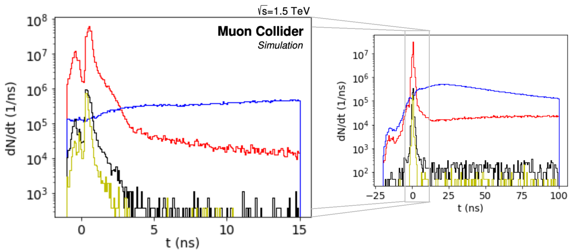
The major contributors to BIB are photons, neutrons and electrons/positrons. The time at which BIB exits the machine in the IR is spread over a wide range but the major part is concentrated around the beam crossing time (), as shown by the top panel of Fig. 4.
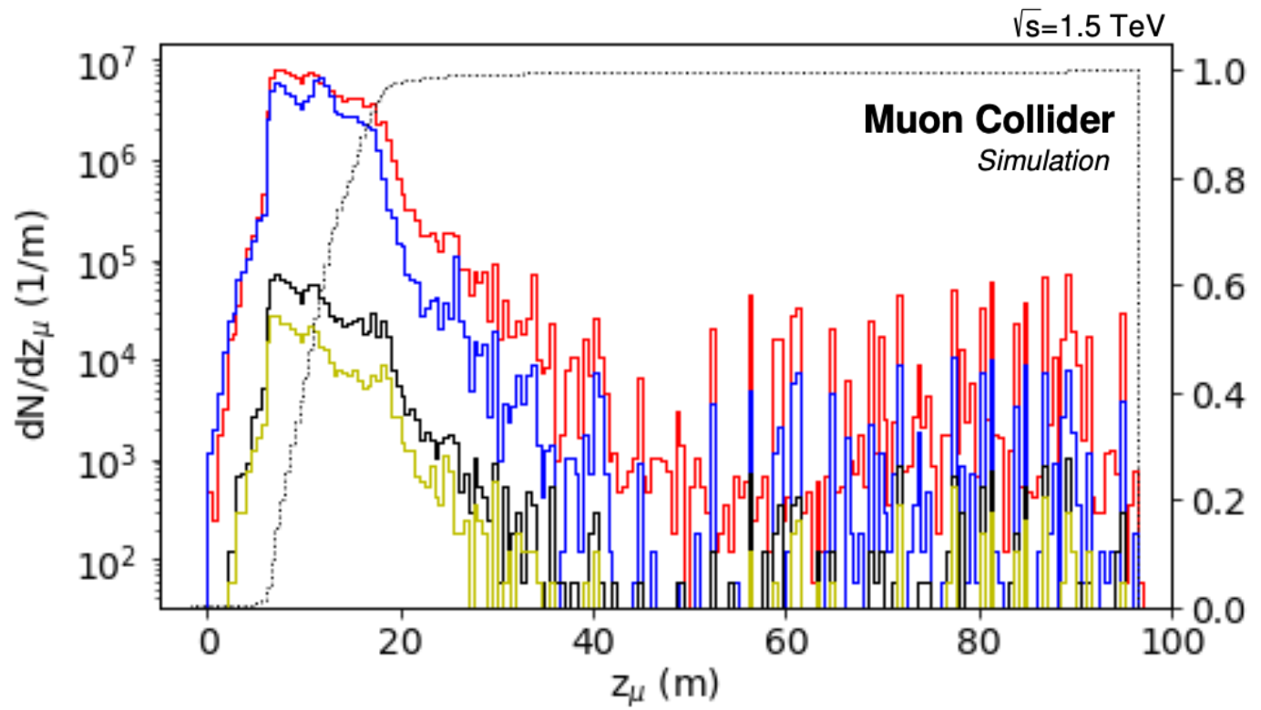
The bottom panel of Fig. 4 reports the longitudinal distribution of primary decays generating the most relevant BIB families: the cumulative function shows it is enough to consider decays within from the IP. On the contrary, simulations show that to correctly account for the secondary , it is necessary to consider primary decays up from the IP.

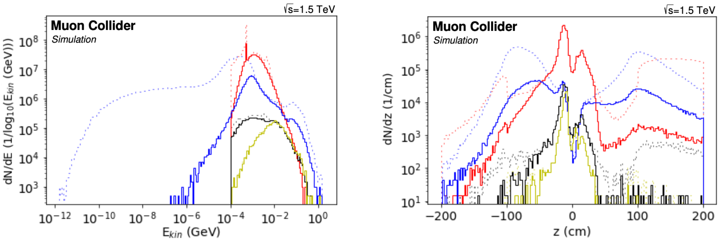
The kinetic energy distribution of most relevant BIB particle types is reported in Fig. 5. Energy cutoffs have been applied in the simulation at 100 keV for , , , charged hadrons and at 10-14 GeV for neutrons. The nozzles act in a very significant way in cutting out the high energy BIB component: as we can notice the BIB particles entering the detector hall have kinetic energy below few GeVs. Only charged hadrons and secondary muons can reach much higher energies but their number is quite low, in the order of 104 and 103, with respect to 107 photons, neutrons and 105 electrons, positrons.
Most of the BIB exits the machine in the region around the IP and by considering a time cut within -1 and 15 ns, which is the most relevant for the detector measures, a big portion of photons and neutrons is removed, as displayed by the left panel of Fig. 5.

2.3 Implications of higher beam energies
FLUKA simulations at TeV and TeV are currently under development. Since the MDI has not yet been optimized for those energies, the one designed for TeV has been adopted. In both cases the preliminary results show a BIB with intensity of the same level as in the TeV configuration characterized by spatial and temporal structures very similar to those presented in the previous section. A careful optimization of machine lattice and MDI is expected to further suppress BIB in the detector region.
3 Overview of the Detector design
The Muon Collider Detector (MCD) follows the classical cylindrical layout typical for multipurpose detectors of symmetric collisions and the specific geometry used for simulation studies in this work has the reference code MuColl_v1. The rendering of the detector geometry is presented in Fig. 6, with the dimensions of each subsystem summarised in Table 2. A cylindrical coordinate system is used with its centre placed at the nominal interaction point. The axis is defined as the moving direction of the beam. The axis is defined to point towards the inner part of the ring and the axis therefore pointing upwards. Cylindrical coordinates are often used with , and denoting the radial distance from the interaction point, the polar and azimuthal angles respectively. Pseudo-rapidity is also used in some cases for convenience.
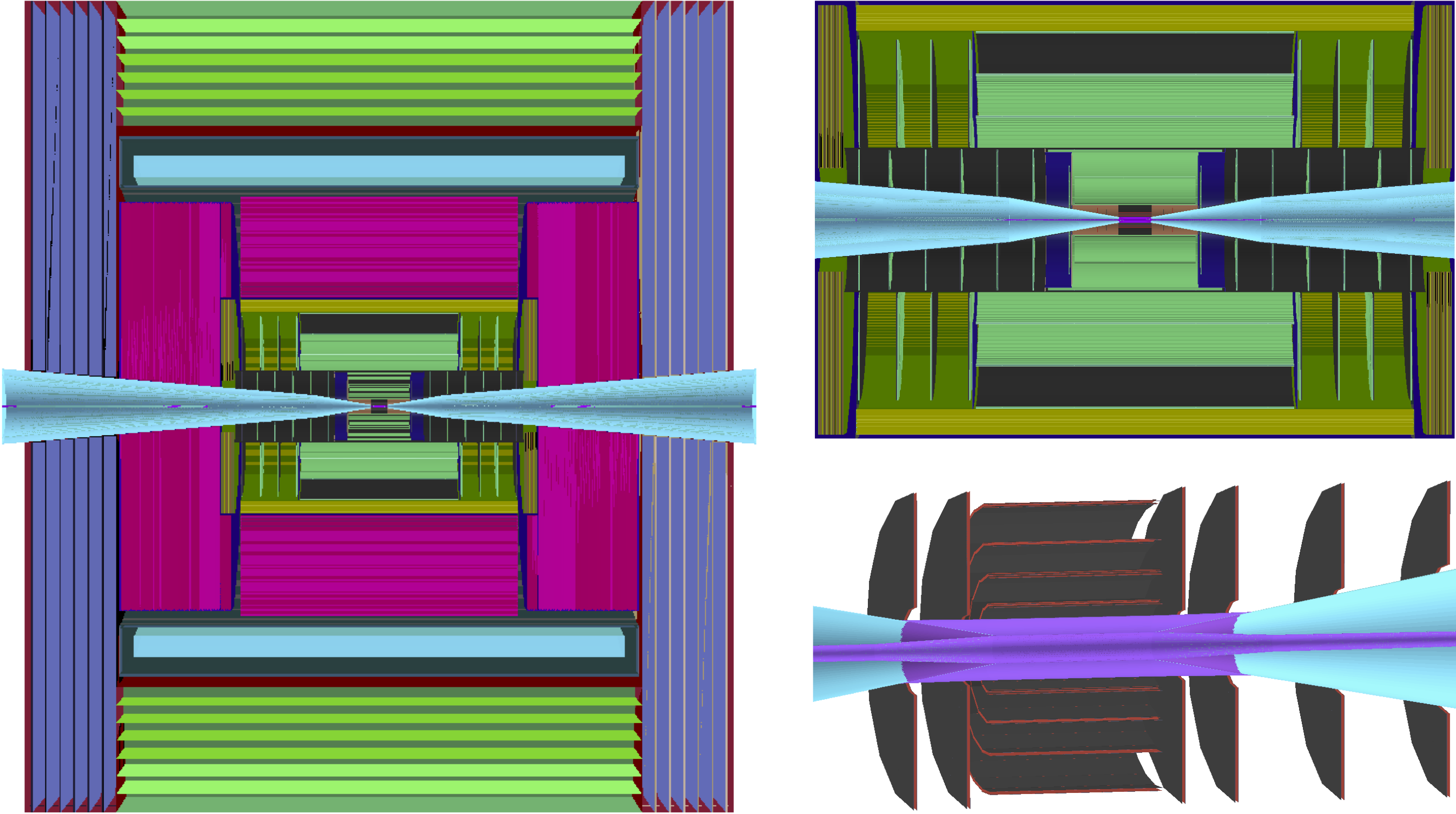
Starting from the Be beampipe with a radius of \qty22\milli, the Vertex Detector is the closest to the IP with its innermost layer having a radius of only \qty30\milli. It is followed by the Inner and Outer Trackers. The three sub-systems complete the all-silicon Tracking Detector, which operates in the strong magnetic field of \qty3.57 provided by the superconducting solenoid, to reconstruct trajectories and transverse momenta () of charged particles. High-granularity sampling ECAL and HCAL calorimeters are arranged outside of the Tracking Detector and provide measurements of electromagnetic and hadronic showers respectively, with fine longitudinal segmentation: 40 layers in ECAL and 60 layers in HCAL. Outside of the superconducting solenoid is the Muon Detector based on RPC technology with its iron yoke closing the magnetic field. It is worth noting that accurate timing information from all sub-systems is an essential component of the detector, as it allows rejecting a large fraction of BIB.
| Subsystem | Region | R dimensions [cm] | Z dimensions [cm] | Material |
| Vertex Detector | Barrel | Si | ||
| Endcap | Si | |||
| Inner Tracker | Barrel | Si | ||
| Endcap | Si | |||
| Outer Tracker | Barrel | Si | ||
| Endcap | Si | |||
| ECAL | Barrel | W + Si | ||
| Endcap | W + Si | |||
| HCAL | Barrel | Fe + PS | ||
| Endcap | Fe + PS | |||
| Solenoid | Barrel | Al | ||
| Muon Detector | Barrel | Fe + RPC | ||
| Endcap | Fe + RPC |
The design of the MuColl_v1 detector is largely based on the CLICdet geometry developed by CLIC collaboration, with the details about technologies used for each component documented in Ref. [62]. The only subsystem with significant changes to its design is the Tracking Detector, which is described in the following.
3.1 Tracking Detector
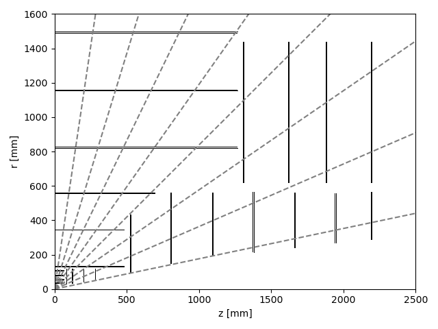
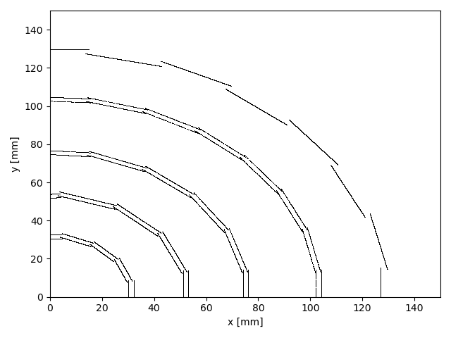
The tracking detector is assumed to follow the typical design of an all-silicon tracker. The geometry is shown in Fig. 7. It consists of three sub-detector; the Vertex Detector, Inner and Outer Trackers. All three are split into a central barrel section and a forward end-cap section. The Vertex Detector is made from 4 double-layers with a \qty2 gap to improve secondary vertex resolution. The forward coverage is limited by the presence of the tungsten nozzle shield.
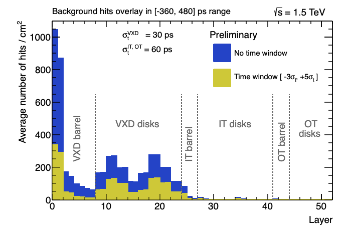
The Tracking Detector returns 4-dimensional hit coordinates; the three positional dimensions and precision timing information. The timing information plays a critical role in reducing the effective hit density from BIB. Fig. 8 shows the timing distribution (corrected for time-of-flight) of hits from a collision compared to those induced by BIB. The spatial and timing resolutions assumed in the detector simulations are summarized in Table 3.

| Vertex Detector | Inner Tracker | Outer Tracker | |
| Cell type | pixels | macropixels | microstrips |
| Cell Size | \qty25 \qty25 | \qty50 \qty1 | \qty50 \qty10 |
| Sensor Thickness | \qty50 | \qty100 | \qty100 |
| Time Resolution | \qty30 | \qty60 | \qty60 |
| Spatial Resolution | \qty5 \qty5 | \qty7 \qty90 | \qty7 \qty90 |
4 Detector Simulation Software
Full simulation of a single collision event involves several stages:
-
1.
generation of all stable particles entering the detector;
-
2.
simulation of their interaction with the passive and sensitive material of the detector;
-
3.
simulation of the detector’s response to these interactions;
-
4.
application of data-processing and object-reconstruction algorithms that would happen in a real experiment.
The first stage of generating stable input particles is handled by standalone software, such as Monte Carlo event generators for the interaction and FLUKA or MARS15 for the BIB particles. The rest of the simulation process is performed inside the iLCSoft framework [63] previously used by the CLIC experiment [64] and now forked for developments of Muon Collider studies [65]. Particle interactions with the detector material are simulated in GEANT4 [55], while detector response and event reconstruction are handled inside the modular Marlin framework [66]. The detector geometry is defined using the DD4hep detector description toolkit [67], which provides a consistent interface with both the GEANT4 and Marlin environments. More detail about the software structure and computational optimization methods used for simulating such a large number of BIB particles is documented in Ref. [68].
4.1 Detector digitization
Response of each sensitive detector to the corresponding energy deposits returned by GEANT4 is simulated by dedicated digitization modules implemented as individual Marlin processors.
The Tracking Detector uses Gaussian smearing to account for the spatial and time resolutions of local hit coordinates on the sensor surface and the time coordinate. The assumed resolution values are listed in Table 3. Acceptance time intervals, individually configured for each sub-detector, are used for replicating the finite readout time windows in the electronics of a real detector and to reject hits from asynchronous BIB particles. The result of this simplified approach is one-to-one correspondence between the GEANT4 hits and digitized hits, which ignores the effect of charge distribution across larger area due to the Lorentz drift and shallow crossing angles with respect to the sensor surface. These effects are taken into account in the more realistic tracker digitization code that is currently under development and will allow stronger BIB suppression based on cluster-shape analysis.
ECAL and HCAL detectors are digitized using realistic segmentation of sensitive layers into cells by summing all energy deposits in a single cell over the configured integration time of \qty±250\pico. Time of the earliest energy deposit is consequently assigned to the whole digitized hit. The same digitization approach is used also for the Muon Detector.
5 Charged particle reconstruction
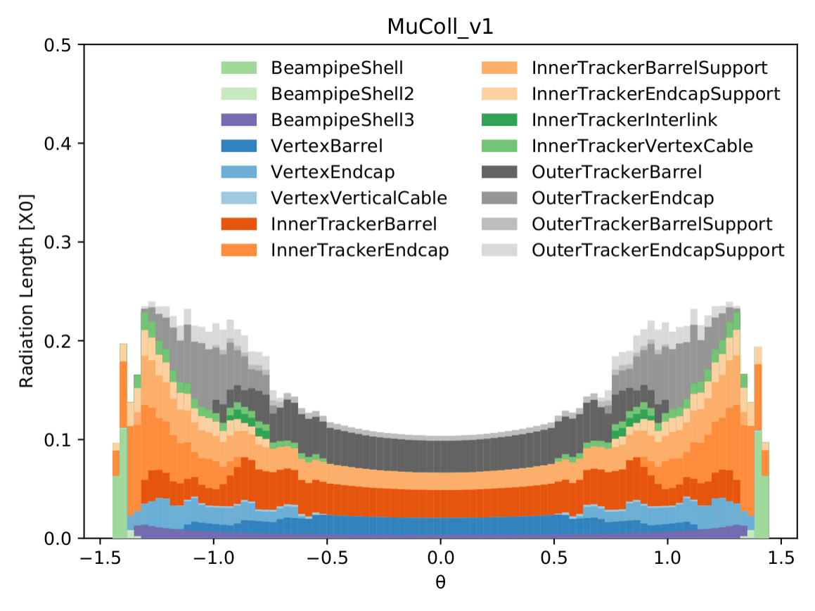
In the magnetic field of MCD a charged particle will follow a helix trajectory aligned with the axis. The radius of curvature in the transverse plane is proportional to the magnetic field (\qty3.57) and the transverse momentum of the particle. Deviations from a perfect helix can occur due to multiple-scattering, ionizing energy losses and bremsstrahlung. The first two are a direct function of the detector material. The amount of radiation lengths that a particle traverses through the tracking detector when starting from the nominal collision point is shown in Fig. 9.
The charged particle trajectory is reconstructed from hits positions in the silicon tracking detector. The reconstructed object is called a track. A track consists of a set of hits (one per layer) and five fitted parameters describing the helix. A track reconstruction algorithm can roughly be broken up into two steps: pattern recognition to identify the hits belonging to a single track and fitting the hit coordinates by a track model to deduce the relevant track parameters.
Track reconstruction at the Muon Collider is complicated by the presence of a huge number of hits in the silicon sensor originating from the Beam Induced Background (BIB-hits). The density of BIB hits is ten times larger than the expected contribution from pile-up events at a High Luminosity LHC detector. Table 4 compares the hit density between the MCD and ATLAS Inner TracKer (ITk) upgrade for HL-LHC operation [69, 70]. The increase in possible hit combinations creates a challenge for the hit pattern recognition step. It is crucial to reduce the amount of hits at the input to a track reconstruction algorithm through alternate means, such as precision timing information. The BIB hits are out-of-time with hard collision hits after the time-of-flight correction has been applied. By applying a time window, the hit density can be reduced by a factor of two as seen in Fig. 10.
| ATLAS ITk Layer | ITk Hit Density [\unit^2] | MCD Equiv. Hit Density [\unit^2] |
|---|---|---|
| Pixel Layer 0 | 0.643 | 3.68 |
| Pixel Layer 1 | 0.022 | 0.51 |
| Strips Layer 1 | 0.003 | 0.03 |
The spatial distribution of BIB-hits is also unique. They are different from hits created by pile-up. Pile-up hits come from real charged particle tracks originating from multiple vertices in the collision region. On the other hand, BIB-hits come from a diffuse shower of soft particles originating from the nozzles. The compatibility of a track with a trajectory originating from the luminous region provides an important handle for differentiating "real" tracks of charged particles produced in the primary collision and "fake" tracks generated from random combinations of BIB-hits.
The remainder of this section describes three approaches that were studied for track reconstruction at the MCD. The first two use the Conformal Tracking (CT) algorithm developed for the clean environment of the electron-positron colliders [71]. However in the presence of BIB, the CT algorithm takes weeks to reconstruct a single event and is impractical for large-scale production of simulated data. To ease the computational effort, the input hits are first reduced by either defining a Region of Interest (Section 5.1) or by exploiting the double-layered Vertex Detector to select only hit pairs pointing to the collision region (section 5.2). The third approach (Section 5.3) uses the Combinatorial Kalman Filter (CKF) [72, 73, 74] algorithm developed for the busy environment of hadron colliders. It can perform track reconstruction in a reasonable time without requiring any additional filtering of input hits.
It should be noted that the CT and CKF algorithms have very different software implementations that are responsible for much of the difference in their performance. The CKF algorithm is implemented using the A Common Tracking Software (ACTS)[75] library that is heavily optimized for efficient computing. The same is not true for the CT algorithm implemented directly in iLCSoft with less emphasis on computational efficiency. It is possible that part of the computational improvements come from code quality alone. For example, the ACTS Kalman Filter implementation is a factor 200 faster than the default iLCSoft implementation given the same inputs. This demonstrates the advantage of an experiment-independent track reconstruction library developed by a dedicated team with strong computing expertise.
The expected performance is assessed using a sample of single muons originating at the interaction point. BIB-hits are overlaid, unless explicitly noted. Two set of samples are used; one set is generated with the muon having a fixed momentum of , and GeV and a uniform distribution in . The second set is generated at discrete values of and uniform transverse momentum distribution in the GeV range. The chosen values correspond to particles expected to leave hits entirely in the endcap system, some in the barrel and some in the endcap, and entirely in the barrel region, respectively.
5.1 Conformal Tracking in Regions of Interest
The Conformal Tracking algorithm is based on Ref [71] and implementation in iLCSoft. The algorithm is designed and optimized to find charged particles in very clean environments, as the ones in colliders. The conformal mapping technique [76] is combined with cellular automaton approach [77] to increase the acceptance of non-prompt particles.
Due to the very large hit multiplicity from BIB-hits, running such an algorithm for the full event is prohibitive in terms of CPU and memory resources. Instead a region-of-interest approach is used, where hits to be considered are pre-selected based on existing objects reconstructed in either the calorimeters or the muon system. To assess tracking performance only hits within a cone of around the signal muon were selected as input to the CT algorithm, where .
Fig. 11 (left) shows the reconstruction efficiency as a function of ; a muon is considered reconstructed if at least half of the hits associated to the track have been originated by the muon. Optimal reconstruction efficiency is achieved throughout the spectrum, with a somewhat smaller efficiency for very forward particles due to their proximity with the nozzle and much larger expected occupancy in the region. The latter is expected to be recovered by a more dedicated tuning of the algorithm or by using one of the algorithms described in the next sections.
Fig. 11 (right) shows transverse momentum resolution as a function of polar angle . The resolution is computed by comparing reconstructed and generated and shown divided by . A localized degradation of the resolution can be seen around , corresponding to the barrel-endcap transition; in addition, the feature is enhanced by the non-physical lack of spread of the muon originating point. It is expected that a more realistic simulation of the luminous region as well as future optimizations of the tracker layout will mitigate such localized degradation to negligible levels.
Fig. 12 shows the resolution on the impact parameter (left) and the resolution on the longitudinal impact parameter (right) as a function of the polar angle . Similarly to the case of the resolution on , the resolution on and slightly degrades in the barrel-endcap transition region, around .


5.2 Conformal Tracking with Double Layers
The Vertex Detector is constructed using double-layers (DL). A double-layer consists of two silicon detector layers separated by a small distance (\qty2mm for MCD). This concept will also be used by the CMS Phase-II tracking detector[78] to reduce the hit combinatorics for a fast track reconstruction in their trigger system. It works by selecting only those hits that can form a pair with a hit from the neighboring layer that in aligned with the interaction point (IP). If there is no 2nd hit in the double-layer to form a consistent doublet the hit is discarded. This approach is particularly effective for rejecting BIB hits, because BIB electrons are very likely to either stop in the first layer due to their very low momentum, or to cross the double-layer at shallow angles, creating doublets that are not aligned with the IP. The DL filtering implemented in our simulation software is based on the angular distance between the two hits of a doublet when measured from the interaction point, as demonstrated in Fig. 13. For simplicity the two variables used for filtering are the polar () and azimuthal () angle differences.
In practice there are several limitations to the precision of alignment that can be imposed by the DL filtering while maintaining high efficiency for signal tracks. The first is driven by the finite spatial resolution of the pixel sensors, which limits the minimum resolvable displacement between the two hits of a doublet.
Its position needs to be known beforehand and any uncertainty will result in an inefficiency. The latter point is also important for displaced particles (ie: secondary vertices of -mesons) that do not originate from the IP.
For simplicity the two variables used for filtering are the polar () and azimuthal () angular distances. Fig. 15 shows the distributions of and in single-muon events with a realistic beamspot in the first layer of the vertex detector. The distribution in other double-layers for muons are shown in Fig. 14. The bi-modal nature of the distribution for low energy muons is the result of the circular path that charged particle take in the transverse plane. This biases DL filtering toward charge particles with higher unless very loose cuts are used.
Table 5 lists the two operating points (loose and tight) used to filter hits for the CT algorithm in two stages. Fig. 16 shows the hit multiplicity (mostly BIB-hits) as a function of VXD layer.
The loose working point targets high efficiency reconstruction of muons with the realistic beamspot size (Fig. 15). It reduces the number of hits in the innermost double-layer by a factor of two. This reduces the CT reconstruction time from to . While significant, this is still not practical for sample production. Instead the loose working point is used with a special CT configuration as a first stage of a two-stage reconstruction process. The first stage reconstructs high-\pT tracks to precisely determine the IP position, which can be used for
The tight working point is optimized for the scenario when the interaction point is precisely known (Fig. 14). It has a hit survival rate of in the inner-most layer. This reduces the hit multiplicity enough for the CT algorithm to complete in . It is used as the second stage of the track reconstruction algorithm, with the IP determined from the first-stage.
The two-stage doublet-layer filtering provides a computationally viable method to track reconstruction in the presence of the BIB. However its efficiency is very limited for reconstructing non-prompt particles, including -meson decays.


| Barrel | Endcap | ||||||||
| Layer IDs | 0,1 | 2,3 | 4,5 | 6,7 | 0,1 | 2,3 | 4,5 | 6,7 | |
| Loose DL selections | Max. (mrad) | 2.8 | 2.0 | 1.7 | 1.5 | 2.1 | 1.7 | 1.6 | 1.5 |
| Max. (mrad) | 35 | 18 | 10 | 6.5 | 3.5 | 1.5 | 0.7 | 0.5 | |
| Hit surival fraction | 55% | 18% | |||||||
| Tight DL selections | Max. (mrad) | 3.0 | 2.0 | 1.6 | 1.5 | 2.2 | 1.8 | 1.7 | 1.6 |
| Max. (mrad) | 0.5 | 0.4 | 0.3 | 0.25 | 0.2 | 0.18 | 0.12 | 0.1 | |
| Hit survival fraction | 2% | 2% | |||||||
5.3 Combinatorial Kalman Filter
The Combinatorial Kalman Filter (CKF) algorithm seeded using hit triplets was implemented using the ACTS library v13.0.0. The implementation is a Marlin Processor that serves as a drop-in replacement for the existing tracking Processors. In addition to providing an alternate algorithm designed for large hit multiplicity, ACTS also provides a heavily optimized code for fast computation. The triplet seeding + CKF used in this section reconstructs tracks at the rate of \qty4min/event. It provides the first practical and comprehensive tracking solution for the MCD.
The seeds for the CKF algorithm are formed from hit triplets in the four layers of the Vertex Detector. Only hits in the outer half of doublet layer are considered. Several heuristics are use to determine if each triplet is compatible with a track and can be used as a seed. The seeding algorithm is configured using the ACTS default values, with the exception of
-
•
radial distance between hits is between \qty5 and \qty80,
-
•
minimum estimated \pT is \qty500MeV,
-
•
maximum forward angle of \qty80°,
-
•
extrapolated collision region is within \qty1mm of detector center,
-
•
average radiation length per seed is 0.1,
-
•
allowed amount of scattering is \qty50σ,
-
•
the middle hits in each seed are unique.
This configuration has not been fully optimized. For example, the size of the collision region is smaller than the expected beam-spot size. Also one needs to explore the use of the Outer Tracker for seeding. Its lower BIB-hit multiplicity can allow the loosening of some requirements.
Around 150,000 seeds are found per event. The efficiency of the seeding algorithm is shown in Fig. 17. Seeds are found for more than 90% of the muons with \pT>\qty2GeV. Loosening the collision region definition increases the amount of fake seeds and reduces the seed finding efficiency due to the seed overlap removal. The latter can be addressed, at a cost in run time, by allowing multiple seeds to share the same middle hit.


The CKF is run inside-out, meaning that the track extrapolation starts from the inner-most seed hit and continues outward in the radial direction. The initial track parameters are estimated from the seed. The CKF algorithm has only two tunable parameters that are set as follows;
-
•
maximum one (closest) hit added at each layer,
-
•
hit search window at each layer of \qty10χ^2.
As with the seeding algorithm, these values are not optimized. The consideration of only a single hit at each layer means that the CKF algorithm will not branch to consider multiple track candidates for a single seed. This seems very tight, however a good tracking reconstruction efficiency is still seen. This underlines the difference between BIB and pile-up; the BIB-hits are a "random" background that is not compatible with the trajectory of a track.
Fig. 18 shows the track reconstruction efficiency as a function of particle \pT and for single muon events with . Muons with are reconstructed with 90% efficiency or greater even in the presence of BIB. There is a considerable amount of fake tracks ( per event). Fig. 19 compares the \pT distribution and the associated number of hits between real and fake tracks. Fake tracks are mostly at low \pTand are associated with a significantly smaller number of hits. The latter further underlines the randomness of the BIB-hits and provides a handle for reducing the fake rate.


Fig. 20 shows the track reconstruction efficiency in a sample containing Higgs bosons decaying to two -quarks. This is a practical demonstration CKF performance on a realistic event. Maintaining a good track reconstruction efficiency as a function of production radius is important for identifying secondary vertices of -mesons. The tight configuration maintains above 70% efficiency up to \qty5. While not perfect, it is a significant improvement over the inefficiency of doublet-layer filtering required for CT.


6 Jets
Hadronic jets are fundamental objects in a Muon Collider experiment. As an example, the measurements of the tri-linear and quadri-linear Higgs couplings rely on the reconstruction and identification of jets from the Higgs boson decay, as the dominant decay signature of the Higgs boson is into -quarks pair, with a branching ratio of . Jet reconstruction is one of the most difficult reconstruction tasks at a Muon Collider, since almost all sub-systems are involved, and the impact of the BIB is significant in all of them, with different features in different sub-detectors. The jet reconstruction algorithm employed is described in this section, and its performance is discussed. The algorithm has been designed to reconstruct jets in the presence of the BIB, but it is far from being fully optimized, and further studies are needed in the future. However we are going to demonstrate that even at this stage the jet reconstruction can achieve a decent performance. Given the high level of details of the full simulation (including the BIB impact) this give us the confidence that measurements with jets are possible at a Muon Collider, and further dedicated advancements on MDI, detectors and reconstruction algorithms would go in the direction of improving the physics reach. The algorithm works as follows:
-
1.
tracks are reconstructed using the Combinatorial Kalman Filter algorithm and are filtered depending on the number of hits in the sub-systems;
-
2.
calorimeter hits are selected by requiring a hit time window and an energy threshold;
-
3.
tracks and calorimeter hits are used by the PandoraPFA algorithm to obtain reconstructed particles;
-
4.
the reconstructed particles are clustered into jets with the algorithm;
-
5.
requirements are applied to remove fake jets;
-
6.
a jet energy correction is applied.
The jet performance has been evaluated on simulated samples of , and dijets, where stands for a light quark (, or ). These samples have been generated with an almost uniform dijet distribution from 120 to \qty200GeV. Samples of and at TeV are also used to study the dijet invariant mass resolution. The BIB at TeV has been overlayed with all the samples.
6.1 Track filter
Tracks are reconstructed using the Combinatorial Kalman Filter algorithm described in Section 5.3. Since more than 100k fake tracks per event are found in this way, they are filtered depending on the number of hits in the Vertex Detector and Inner Tracker. In Fig. 21 hit distributions for tracks from -jets and BIB are compared.


A number of Vertex Detector hits greater than 3 and a number of Inner Tracker hits greater than 2 are required for each track, reducing the average number of BIB combinatorial tracks per event from more than 100k to less than 100.
6.2 Calorimeter hit selection
Calorimeter hits are filtered depending on the normalized hit time, defined as , where is the absolute hit time, is the collision time, is the speed of light, and is the hit distance from the origin of the reference system. A time window of ps is applied to remove most of the BIB hits but preserving the signal, as can be seen in Fig. 22.

As rule of thumb we can assume that a time window of width is applicable if the Full Width at Half Maximum (FWHM) of the cell time resolution is below . Therefore, in this particular case, we assume a FWHM of at least 167 ps, that should be achievable by state-of-the-art calorimeter technologies.
Several calorimeter hit energy thresholds have been tested, in order to reduce hits produced by BIB. It has been found that a threshold of 2 MeV applied to both ECAL and HCAL is a compromise between jet performance and computing time. In fact this requirement reduces the average number of ECAL Barrel hits from 1.5M to less than 10k. The computing time of the jet algorithm exponentially grows with the number of calorimeter hits, therefore with the current resources we are not able to reduce the thresholds far below 2 MeV. However the impact of reducing the thresholds at the close value of 1 MeV is described in Section 6.7.
6.3 Particle flow, jet clustering and fake jet removal
Calorimeter hits and tracks are given as input to the PandoraPFA algorithm, that produces as output reconstructed particles known as particle flow objects. The PandoraPFA algorithm is described in detail in [79]. Then particle flow objects are clustered into jets by the algorithm. A cone radius of is used.
At this point an average number of 13 fake jets per event is reconstructed, which need to be removed by applying additional quality criteria. The number of tracks in the jet has been found to be the most discriminating feature between -jets and fake jets, as shown in Fig.23 (left).


It can be seen that most of the fake jets from BIB have no tracks associated to them. Therefore, requiring at least one track allows to greatly reduce the rate of fake jets. In Fig. 23 (right) the fake jet rate as a function of jet is presented. It has been obtained using a sample of dijets and defined as the average number of reconstructed fake jets per event, which is well below 1%.
6.4 Jet momentum correction
The jet 4-momentum is defined by the sum of 4-momenta of particles that belong to the jet. The jet axis is identified by the jet momentum direction. We define the fiducial region of the jet reconstruction by selecting jets with pseudorapidity , where , with angle between the jet axis and beam axis.
In order to recover the energy lost by reconstruction inefficiencies, as well as to take into account BIB contamination, a correction to the jet 4-momentum is applied. This correction has been determined by comparing the reconstructed jet with the corresponding truth-level jet . Truth-level jets are defined as jet clustered by applying the algorithm to Monte Carlo particles. Reconstructed and truth-level jets are matched if their distance is below 0.5, i.e.:
where and are respectively the pseudo-rapidity the azimuthal angle differences between the reconstructed-level jet axis and truth-level jet axis. If more than one reconstructed jet is matched to the same truth-level jet than the one with lower is chosen.
The correction is evaluated in five equal-width intervals of reconstructed between 0 and 2.5. Each pseudo-rapidity interval is further divided in 19 equal-width intervals of reconstructed between 10 and 200 GeV. For each interval the average and standard deviation of the truth-level jet distribution is calculated. Transfer functions as then obtained in each interval by fitting the average truth-level jet as a function of reconstructed jet . Examples of transfer functions are shown in Fig. 24. These functions are then used obtain the scale factor that is applied to each component of the reconstructed 4-momentum.


6.5 Jet reconstruction performance
The -jet reconstruction performance is first evaluated on the simulated sample of dijets. In Fig. 25 (left) the -jet efficiency as a function of the true -jet is shown. It is worth noting that this is only the jet reconstruction efficiency, while the flavor tagging performance is studied in Section 6.8. The efficiency is around 90 in the central region, but there is a drop for , where the efficiency is 20. It has been verified that this drop is mainly due to the fake jet removal requirement, since many jets without reconstructed tracks are found in the forward region. In Fig. 25 (right) the -jet efficiency as a function of the true -jet in the region is presented, and it goes from 82 at low to 95 at higher .


The relative difference between reconstructed and true -jet is shown in Fig. 26 (right): the standard deviation of this distribution, directly related to the jet-axis angular resolution, is 14. The -jet resolution as a function of the true -jet is shown in Fig. 26 (right).


The resolution goes from 35 for jet around 20 GeV to 20 for high jet .
The jet reconstruction performances obtained separately in the , and samples and in the central region () are compared in Fig. 27. It can be seen that both the efficiencies and resolutions are of the same order, however some differences exist between the jet flavours: it has been checked that these are mainly due to different jet distributions in the three samples.


6.6 Invariant mass reconstruction of Higgs and Z bosons to b-quarks
The jet reconstruction is applied to the simulated samples of and to probe the dijet invariant mass reconstruction. The invariant mass separation between these two processes is of paramount importance for physics measurements at the muon collider. In this study both jets are required to have GeV and . In Fig. 28 the dijet invariant mass distributions for and are shown. The distributions are fitted with double gaussian functions, and the shapes are compared. A relative width, defined as the standard deviation divided by the average value of the mass distribution, of 27(29) for () is found. It can be seen that a significant separation is achieved.


6.7 Future prospects on jet reconstruction
Before discussing the heavy-flavour jet identification, we notice that, at this stage, the jet reconstruction algorithm can be improved in several ways. In this Section some guidelines are given:
-
•
track filter: it has been verified that the track filter has a different impact in the central and the forward region, in particular the efficiency in the forward region is lower. An optimized selection should be defined,
-
•
calorimeters threshold: the hit energy threshold has been set to the relatively high value of 2 MeV, as a compromise between computing time and jet reconstruction performance. This is a major limitation in the jet performance as can be seen in Fig. 29 (left), where the dijet invariant mass, reconstructed without the presence of the BIB, is compared between 2 MeV and 200 KeV thresholds. However reducing this threshold is not an easy task, given the large number of calorimeter hits selected from the BIB that contaminate the jet reconstruction. This is shown in Fig. 29 (right), where can be clearly seen that the performance at 1 MeV threshold is degraded with respect to 2 MeV. To tackle this problem an optimized algorithm should be developed: as an example thresholds that depend on the sensor depth could by applied, since the longitudinal energy distribution released by the BIB is different from the signal jets as shown in Fig. 30 (right). A generalization of this idea could be the application of a multivariate-algorithm trained to select signal hits and reject BIB hits,
-
•
fake jet removal: the fake jet removal applied in this study has an impact in reducing the jet efficiency in the forward region. Moreover this issue is highly dependent from the calorimeter thresholds. A fake removal tool based on machine learning and with jet sub-structure observables as input should be developed to solve this task.


6.8 Heavy-flavor jet identification
The -jet identification algorithm described in this section relies on the reconstruction of the secondary vertices inside the jet cones, that are compatible with the decay of the heavy-flavour hadron.
For the secondary vertices reconstruction, tracks are reconstructed with the Conformal Tracking algorithm described in Section 5.1, where the region of interests are defined by cones with around the jet axes. In order to reduce the computational time, the Double Layer filter (see Section 5.2) is applied to reduce the number of hits due to BIB. The effect of this filter on the secondary vertex reconstruction is then corrected to obtain the efficiency prior to its application, as will be explained in Section 6.8.2.
6.8.1 Secondary vertex tagging
The vertexing algorithm employed for the primary and secondary vertex reconstruction is described in detail in [80]. In order to reduce the amount of combinatorial tracks due to BIB, cuts are applied to the reconstructed tracks given as input to the algorithm. The main steps of the algorithm and cuts to the input tracks are here summarized:
-
1.
primary vertex finding: tracks with and are selected and given in input to the primary vertex fitter. Furthermore, to reduce the number of combinatorial short BIB tracks, each track is required to have at least four hits in the vertex detector;
-
2.
tracks selection for secondary vertex finder: tracks not used to reconstruct the primary vertex are given in input to the secondary vertex fitter. Fig. 31 shows the distributions of the total number of hits in the vertex detector for combinatorial BIB tracks and for tracks matched at Monte Carlo level with particles generated by or hadrons decays. A minimum number of 4 hits in the vertex detector is required in order to keep most of the the tracks from and hadrons decay, while rejecting most of BIB tracks.

Figure 31: Number of hits in the vertex detector of BIB combinatorial tracks (red) and of tracks matched with Monte Carlo truth particles coming from or hadrons (blue and black respectively) decay. Distributions are normalized to the unity area. Other cuts on the track \pT , the maximum track (longitudinal impact parameter) and (transverse impact parameter), and the and errors are applied in order to further reduce the amount of BIB tracks. As an example, Fig. 32 (left) shows the distributions of BIB combinatorial tracks and tracks from - or -hadrons decays. By requiring about 80 of the BIB tracks are rejected, while about 85-90 of the tracks from - or -hadrons are kept. The distributions of tracks coming from - and -hadrons and combinatorial BIB tracks are shown in Fig. 32 (right). The selection of tracks with is applied to reject the tails at large that characterize BIB tracks;


Figure 32: Left: distribution of tracks coming from (blue) or (black) hadrons decay and combinatorial BIB (red) tracks. Right: distribution of tracks coming from (blue) or (black) hadrons decay and combinatorial BIB (red) tracks. Distributions are normalized to the number of tracks. -
3.
secondary vertex finding: tracks passing the requirements are used to build two-tracks vertex candidates, that must satisfy the following requirements: the invariant mass must be below 10 GeV and must be smaller than the energy of each track, the position with respect to the primary vertex must lie in the same side of the sum of the tracks momenta, and the of the tracks with respect the secondary vertex position must be below a threshold value, set to 5. Track pairs are also required not to be compatible with coming from the decay of neutral long lived particles. Additional tracks are iteratively added to the two-tracks vertices if they satisfy the above requirements. Tracks associated to more than one secondary vertex are assigned to the vertex with the lowest and removed from other vertices.
6.8.2 SV-tagging performance
In order to evaluate the -tagging efficiency and mis-identification, a truth-level flavour is associated to the reconstructed jets with the following steps:
-
•
first, the truth-level jets are matched with the quarks from Monte Carlo to determine its flavour, requiring a distance R 0.5 between the truth-level jet axis and quark momentum. If more than one truth-level jet is found to match with the same quark, the one with the lowest R is chosen;
-
•
then, the flavour of the reconstructed jets is determined by matching them with the truth-level jets, by requiring a R distance between the jets axes below 0.5;
-
•
if the reconstructed jet do not match with any truth-level jet, it is labeled as fake.
The characteristics of secondary vertices inside reconstructed jets have been studied in order to reduce the mis-identification of , light and fake jets. Fig. 33 shows the distribution of the secondary vertices proper lifetime () for jets, jets and light+fake jets. A cut on 0.2 ns rejects of both and light+fake jets, while keeping of jets. A reconstructed jet is identified (tagged) as jet, if at least one secondary vertex with 0.2 ns is found inside its cone ( 0.5).
The -tagging efficiency is defined as:
| (1) |
where is the number of tagged and truth-matched jets, while is the total number of truth-matched jets. Then, the mistag on and light+fake jets is calculated as:
| (2) |
where is the number of tagged and truth-matched (light+fake) jets, while is the total number of truth-matched (light+fake) jets.
The effect of the Double Layer Filter on the secondary vertex finding efficiency have been evaluated reconstructing , and dijet samples without BIB, with and without the Double Layer filter. The following ratio has been calculated as a function of of the jet and of the angle of the jet axis with respect to the beam ():
| (3) |
where is the number of tagged jets without double layer filter and is the number of tagged jets with the double layer filter. The final tagging efficiencies are then corrected for this ratio, assuming that its value does not change in the presence of the BIB. The -tagging efficiency as a function of the jet and is shown in Fig. 34. The efficiency is around at low and increases up to at high . At low the efficiency is lower () probably due to the presence of the nozzles. The mistag for jets is shown in Fig. 35 and is found to be around . As for -jet efficiency, the mistag increases in the central region of the detector. Fig. 36 (left) shows the mistag for the light and fake jets versus jet , up to 90 GeV, and is found to be lower than below 50 GeV, while increases to at higher jet . Fig. 36 right shows the light+fake jet mistag as a function of .


As for jet reconstruction, the -jet identification algorithm needs further improvements, but a solid starting point has been set. In particular it will take advantage of the advancements in the vertex detector and track reconstruction. Given the impact of the BIB, the features shown in this section are not sufficient to setup an effective -tagging algorithm, therefore this case should be studied by defining a dedicated strategy for the muon collider environment.
7 Photons and Electrons
7.1 Photon reconstruction and identification
The photon reconstruction and identification performance of the muon collider detector is assessed in a sample of 100000 events with a single photon per event. Photons were generated in the nominal collision vertex at the center of the detector, uniformly distributed in energy between 1 and 1500 GeV, in polar angle between and , and in the full azimuthal angle range. The sample was then processed with the detector simulation and fully reconstructed. 40000 events were also reconstructed with the beam-induced background overlaid.
The reconstruction procedure includes the CKF tracking and the calorimeter reconstruction. Prior to track reconstruction, the tracker hits were processed with the Doublet-Layer filter (see Section 5.2). Moreover, to get rid of most of the fake tracks due to the spurious hits from the background, a track quality selection is applied before the track refitting step, which requires at least three hits in the vertex detector and at least two hits in the inner tracker. To reject part of the background hits in the calorimeters, an energy threshold of 2 MeV is applied to both the ECAL and HCAL hits. Photons are reconstructed and identified with the Pandora Particle Flow algorithm. A detailed description of the package can be found in Ref. [79].
The energy threshold of the calorimeter hits and the presence of the beam-induced background affect the energy scale of the reconstructed photons. A correcting factor is applied to the reconstructed photon energy to make the detector response uniform as a function of the photon energy and the photon polar angle. The correction was calculated from a comparison of the reconstructed photon energy with the photon energy at generation level in an independent subsample of events.


Fig. 37 shows a comparison of the photon reconstruction efficiency as a function of the generated photon energy and polar angle with and without the BIB. The efficiencies are defined as the fraction of generated photons in the range and that are matched to a reconstructed photon within a cone .
The dip in the region between the barrel and endcap calorimeters, which is reflected in the efficiency below \qty400GeV .
effect of BIB on energy resolution standard deviation of a Gaussian fit to the distribution of residuals . It may be seen that the BIB degrades significantly the photon reconstructed energy in the region between the barrel and the endcap.


Fig. 39 reports the fraction of photons that are reconstructed and identified as electons.
.
7.2 Electron reconstruction and identification
Performance for electron reconstruction and identification is obtained in a sample of 50000 events with a single electron per event produced at the nominal collision point. The generated electrons are uniformly distributed in energy between 1 and 1500 GeV, in polar angle between and , and in azimuthal angle over the whole range. The sample was processed with the detector GEANT4 simulation and the Marlin reconstruction algorithms. A subsample of 20000 events was also reconstructed with the beam-induced background overlaid.
Electrons are identified by means of an angular matching of the electromagnetic clusters, reconstructed in the same way as Section 39, with tracks reconstructed with the CKF algorithm, as described in Section 5.3 in a cone. The Double-Layer filter was used to clean the tracker hits upstream the track reconstruction and tracks are required to have . In the presence of the beam-induced background, the energy thresholds of the calorimeter hits play a dominant role for an efficient and precise cluster reconstruction. In this study, a threshold of 5 MeV was set. Futher developments and more sophisticated algorithms are needed to improve the cluster reconstruction, particularly in the lower energy regime.


The electron reconstruction and identification efficiencies as a function of the electron generated energy and polar angle are shown in Fig. 40.
The drop at in the left panel is caused by a tracking inefficiency introduced by the Double-Layer filter in the transition region between the VXD barrel and endcap.
8 Muons
Preliminarily, the muon reconstruction has been performed, following CLIC procedure, within the Pandora PFA framework [81], that allows to investigate cluster topologies. A cluster is defined as a combination of hits (one hit per layer) inside a cone and on neighbouring layers. A detailed description of the muon reconstruction algorithm is reported in [64].
The efficiency, defined as the ratio between generated particles associated with a cluster and total generated particles, has been evaluated for single muons with transverse momentum uniformly distributed in the range \qty100MeV-\qty1TeV and polar angle . No BIB was overlaid. The cluster efficiency is higher than 99% for and higher than 98% for .
Muon track resolution is shown in Fig. 41 where is the difference between the generated muon and the of the corresponding Pandora PFA reconstructed track. It results to be less than GeV-1 for GeV and around a factor of 7 better in the barrel region compare to the endcap [82].

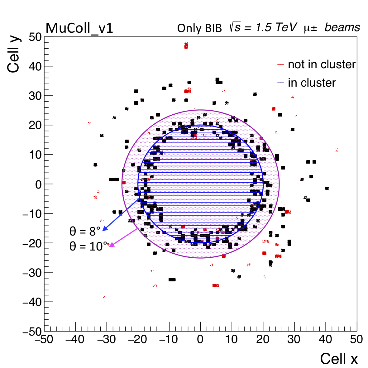
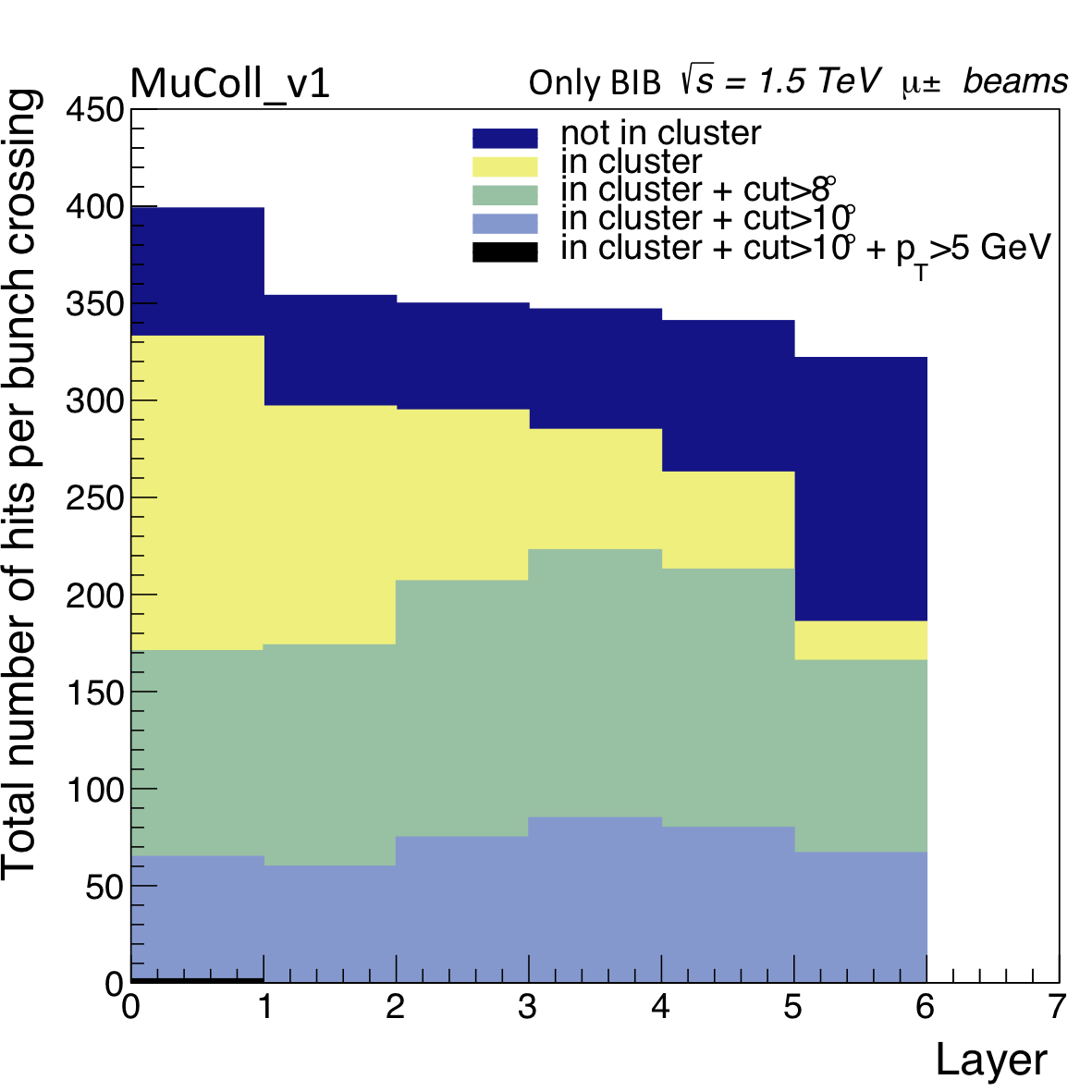
Running the Conformal Tracking algorithm on a full event and Pandora requires an enormous computational effort to reconstruct a single event when BIB is overlaid. Moreover, Pandora reconstruction is fully driven by the tracker where the BIB hit density is very high as already discussed before. At the same time, the BIB occupancy in the muon system is very low compared to other detectors. BIB hits are concentrated in the endcaps around the beam axis (Fig.42 left) and a simple geometrical cut, combined for example with a cut on the track transverse momentum, allows to get rid of almost all the BIB hits (Fig.42 right). This suggests using standalone muon objects to seed the global muon track reconstruction.
A processor has been developed to clusterize muon hits inside a cone with a certain angular aperture . At least hits on five layers are required to make a stand-alone muon track. Reconstructed hits in the Vertex Detector, Inner Tracker and Outer Tracker are then filtered using the region-of-interest approach described in Section 5.1: only hits in a cone of aperture (see below) around the muon stand-alone direction are selected. These hits are then passed to the CT algorithm. At the moment no information coming from the ECAL and HCAL calorimeters is used.


Two different samples have been used to evaluate the performance of the processor:
-
1.
single muons with transverse momentum uniformly distributed in the range 100 MeV-700 GeV and polar angle with no BIB overlaid
-
2.
HZ channel resulting in six muons in the final state at a center-of-mass energy of both with and without BIB.
The angular apertures chosen to maximize track purity and mitigate the background are and .


Efficiencies are defined as the fraction of generated muons that are matched to a track within a cone of aperture 0.01. Figure 43 shows the efficiency as a function of the polar angle both for the first (left) and second sample (right). An efficiency loss is evident in both cases at and due to a limit of the CT algorithm, while the two dips around and are due to tracks with hits both in endcap and barrel that require a specific approach, currently under study.
To study the efficiency as a function of transverse momentum the acceptance region was restricted to to take into account only the region with a high efficiency for CT. Figure 44 shows an efficiency greater than 85% for transverse momentum higher than for both the samples. The drop of the curve at low is due to known effects currently under study, that mostly concern the inefficiency of reconstruction of muons in the region between barrel and endcap and tracks with a high curvature for which the choice of has to be optimized. The muon track transverse momentum resolution (Fig. 45) is comparable with that obtained with CT and Pandora without BIB.
In general the presence of the BIB does not strongly affect the performance: the efficiency is lower only in the endcaps where all the BIB hits are concentrated, and the resolution is just a few percent worse.
9 Luminosity measurement
A precise determination of the luminosity is of crucial importance for any physics absolute cross section measurement since it directly translates to its error. LHC experiments have dedicated detectors, so-called luminometers, installed often the backward/forward region of the detector that are used in combination to the van Der Meer scan method to precisely measure the instantaneous luminosity. The experiments like Belle2[83] and BESIII[84], measure the integrated luminosity by counting the number of events of a process whose cross section is theoretically known with high precision. The most used one is the Bhabha scattering () where, for example, the theoretical uncertainty on at GeV is 0.1% at large angle [85]. Due to the reduced acceptance in the backward/forward region because of the nozzles shielding structure at muon collider, the large angle muon Bhabha ( ) is proposed as a method for the luminosity measurement instead. A first evaluation of the expected precision has been performed by using a sample of -Bhabha generated with Pythia at the center-of-mass energy of \qty1.5TeV. The events are then simulated through the detector and reconstructed by using the Pandora Particle Flow algorithm [79].
Muons with emission angle respect to the beam-pipe are selected. The beam-induced background effects in this angular region are negligible, as shown in Section 8. Two opposite sign charge muons, both with transverse momentum and angle between muons direction pair rad are required. Finally, the di-muon invariant mass has to be GeV. These selection requirements reject almost all the physics background contributions and allow to keep the entire signal sample at TeV. A different center of mass energy, muon reconstruction and sample selection need to be re-optimized.
By assuming an instantaneous luminosity cm-2s-1 and considering a year of data taking ( s) the statistical uncertainty obtained at TeV is 0.2% [86]. This study demonstrates that the method can be applied at the muon collider from the experimental point of view. The expected total uncertainty on the luminosity measurement using this method strongly depends on the accuracy on the theoretical cross section of -Bhabha scattering at large angles, and at high center of mass energy( several TeV). Further theoretical developments are needed in this area.
10 Conclusions
A collider offers a viable path towards a rich and scalable physics program at the energy frontier. One of the biggest challenges in designing a detector for the muon collider environment is the presence of beam-induced background. In this manuscript, we presented the performance of a detector design, including appropriate shielding near the interaction point, that can successfully cope with the expected beam-induced background and reconstruct with high accuracy the main physics observables needed for carrying out the expected physics program. Expected performance for reconstructing charged particles, jets, electrons, muons and photons has been presented, in addition to preliminary results on tagging heavy-flavor jets and measuring the delivered integrated luminosity.
References
- [1] C. Aimè et al., Muon Collider Physics Summary, 2203.07256.
- [2] V. Shiltsev and F. Zimmermann, Modern and Future Colliders, Rev. Mod. Phys. 93 (2021) 015006 [2003.09084].
- [3] K. Long, D. Lucchesi, M. Palmer, N. Pastrone, D. Schulte and V. Shiltsev, Muon colliders to expand frontiers of particle physics, Nature Phys. 17 (2021) 289 [2007.15684].
- [4] J. De Blas et al., The physics case of a 3 TeV muon collider stage, 2203.07261.
- [5] D. Buttazzo, D. Redigolo, F. Sala and A. Tesi, Fusing Vectors into Scalars at High Energy Lepton Colliders, JHEP 11 (2018) 144 [1807.04743].
- [6] R. Franceschini, High(est) energy lepton colliders, Int. J. Mod. Phys. A 36 (2021) 2142016.
- [7] R. Capdevilla, F. Meloni, R. Simoniello and J. Zurita, Hunting wino and higgsino dark matter at the muon collider with disappearing tracks, JHEP 06 (2021) 133 [2102.11292].
- [8] H. Al Ali et al., The Muon Smasher’s Guide, 2103.14043.
- [9] D. Buttazzo, R. Franceschini and A. Wulzer, Two Paths Towards Precision at a Very High Energy Lepton Collider, 2012.11555.
- [10] T. Han, D. Liu, I. Low and X. Wang, Electroweak Couplings of the Higgs Boson at a Multi-TeV Muon Collider, Phys. Rev. D 103 (2021) 013002 [2008.12204].
- [11] R. Capdevilla, D. Curtin, Y. Kahn and G. Krnjaic, A Guaranteed Discovery at Future Muon Colliders, 2006.16277.
- [12] M. Ruhdorfer, E. Salvioni and A. Weiler, A Global View of the Off-Shell Higgs Portal, SciPost Phys. 8 (2020) 027 [1910.04170].
- [13] M. Chiesa, F. Maltoni, L. Mantani, B. Mele, F. Piccinini and X. Zhao, Measuring the quartic Higgs self-coupling at a multi-TeV muon collider, JHEP 09 (2020) 098 [2003.13628].
- [14] A. Costantini, F. De Lillo, F. Maltoni, L. Mantani, O. Mattelaer, R. Ruiz et al., Vector boson fusion at multi-TeV muon colliders, JHEP 09 (2020) 080 [2005.10289].
- [15] R. Capdevilla, D. Curtin, Y. Kahn and G. Krnjaic, No-lose theorem for discovering the new physics of (g-2) at muon colliders, Phys. Rev. D 105 (2022) 015028 [2101.10334].
- [16] N. Bartosik et al., Detector and Physics Performance at a Muon Collider, JINST 15 (2020) P05001 [2001.04431].
- [17] W. Yin and M. Yamaguchi, Muon at multi-TeV muon collider, 2012.03928.
- [18] J. Kalinowski, T. Robens, D. Sokolowska and A.F. Zarnecki, IDM Benchmarks for the LHC and Future Colliders, Symmetry 13 (2021) 991 [2012.14818].
- [19] W. Liu and K.-P. Xie, Probing electroweak phase transition with multi-TeV muon colliders and gravitational waves, JHEP 04 (2021) 015 [2101.10469].
- [20] T. Han, S. Li, S. Su, W. Su and Y. Wu, Heavy Higgs Bosons in 2HDM at a Muon Collider, 2102.08386.
- [21] S. Bottaro, A. Strumia and N. Vignaroli, Minimal Dark Matter bound states at future colliders, JHEP 06 (2021) 143 [2103.12766].
- [22] T. Li, M.A. Schmidt, C.-Y. Yao and M. Yuan, Charged lepton flavor violation in light of the muon magnetic moment anomaly and colliders, Eur. Phys. J. C 81 (2021) 811 [2104.04494].
- [23] P. Asadi, R. Capdevilla, C. Cesarotti and S. Homiller, Searching for leptoquarks at future muon colliders, JHEP 10 (2021) 182 [2104.05720].
- [24] M. Sahin and A. Caliskan, Excited muon production at muon colliders via contact interaction, 2105.01964.
- [25] J. Chen, C.-T. Lu and Y. Wu, Measuring Higgs boson self-couplings with 2 → 3 VBS processes, JHEP 10 (2021) 099 [2105.11500].
- [26] G. Haghighat and M. Mohammadi Najafabadi, Search for lepton-flavor-violating ALPs at a future muon collider and utilization of polarization-induced effects, 2106.00505.
- [27] S. Bottaro, D. Buttazzo, M. Costa, R. Franceschini, P. Panci, D. Redigolo et al., Closing the window on WIMP Dark Matter, 2107.09688.
- [28] C. Sen, P. Bandyopadhyay, S. Dutta and A. KT, Displaced Higgs production in Type-III Seesaw at the LHC/FCC, MATHUSLA and Muon collider, 2107.12442.
- [29] T. Han, W. Kilian, N. Kreher, Y. Ma, J. Reuter, T. Striegl et al., Precision test of the muon-Higgs coupling at a high-energy muon collider, JHEP 12 (2021) 162 [2108.05362].
- [30] P. Bandyopadhyay, A. Karan and R. Mandal, Distinguishing signatures of scalar leptoquarks at hadron and muon colliders, 2108.06506.
- [31] R. Dermisek, K. Hermanek and N. McGinnis, Di-Higgs and tri-Higgs boson signals of muon g-2 at a muon collider, Phys. Rev. D 104 (2021) L091301 [2108.10950].
- [32] S. Qian, C. Li, Q. Li, F. Meng, J. Xiao, T. Yang et al., Searching for heavy leptoquarks at a muon collider, 2109.01265.
- [33] M. Chiesa, B. Mele and F. Piccinini, Multi Higgs production via photon fusion at future multi-TeV muon colliders, 2109.10109.
- [34] W. Liu, K.-P. Xie and Z. Yi, Testing leptogenesis at the LHC and future muon colliders: a scenario, 2109.15087.
- [35] D. Buttazzo and P. Paradisi, Probing the muon anomaly with the Higgs boson at a muon collider, Phys. Rev. D 104 (2021) 075021.
- [36] L. Di Luzio, R. Gröber and G. Panico, Probing new electroweak states via precision measurements at the LHC and future colliders, JHEP 01 (2019) 011 [1810.10993].
- [37] T. Han, Z. Liu, L.-T. Wang and X. Wang, WIMPs at High Energy Muon Colliders, Phys. Rev. D 103 (2021) 075004 [2009.11287].
- [38] J. Chen, T. Li, C.-T. Lu, Y. Wu and C.-Y. Yao, The measurement of Higgs self-couplings through VBS in future muon colliders, 2112.12507.
- [39] R. Capdevilla, D. Curtin, Y. Kahn and G. Krnjaic, Systematically Testing Singlet Models for , 2112.08377.
- [40] C. Cesarotti, S. Homiller, R.K. Mishra and M. Reece, Probing New Gauge Forces with a High-Energy Muon Beam Dump, 2202.12302.
- [41] D. Stratakis et al., A Muon Collider Facility for Physics Discovery, 2203.08033.
- [42] D.V. Neuffer and R.B. Palmer, A High-Energy High-Luminosity Collider, Conf. Proc. C 940627 (1995) 52.
- [43] G.W. Foster and N.V. Mokhov, Backgrounds and detector performance at a 2 2 TeV collider, AIP Conf. Proc. 352 (1996) 178.
- [44] R. Palmer et al., Muon collider design, Nucl. Phys. B Proc. Suppl. 51 (1996) 61 [acc-phys/9604001].
- [45] J.C. Gallardo et al., Collider: Feasibility Study, eConf C960625 (1996) R4.
- [46] C.M. Ankenbrandt et al., Status of muon collider research and development and future plans, Phys. Rev. ST Accel. Beams 2 (1999) 081001 [physics/9901022].
- [47] P. Snopok, M. Berz and C. Johnstone, A New Lattice Design for a 1.5-TeV CoM Muon Collider Consistent with the Tevatron Tunnel, Conf. Proc. C 070625 (2007) 3483.
- [48] Y. Alexahin and E. Gianfelice-Wendt, A 3 TeV Muon Collider Lattice Design, Conf. Proc. C 1205201 (2012) 1254.
- [49] Y. Alexahin et al., Muon Collider Higgs Factory for Snowmass 2013, in Community Summer Study 2013: Snowmass on the Mississippi, 8, 2013 [1308.2143].
- [50] N. Bartosik, A. Bertolin, L. Buonincontri, M. Casarsa, F. Collamati, A. Ferrari et al., Detector and physics performance at a muon collider, Journal of Instrumentation 15 (2020) P05001–P05001.
- [51] N.V. Mokhov and S.I. Striganov, Simulation of backgrounds in detectors and energy deposition in superconducting magnets at colliders, AIP Conf. Proc. 372 (1996) 234.
- [52] N.V. Mokhov and S.I. Striganov, Detector Background at Muon Colliders, Phys. Procedia 37 (2012) 2015 [1204.6721].
- [53] F. Collamati, C. Curatolo, D. Lucchesi, A. Mereghetti, N. Mokhov, M. Palmer et al., Advanced assessment of beam-induced background at a muon collider, JINST 16 (2021) P11009 [2105.09116].
- [54] S. Jindariani et al., Promising Technologies and R&D Directions for the Future Muon Collider Detectors, 2203.07224.
- [55] GEANT4 collaboration, GEANT4–a simulation toolkit, Nucl. Instrum. Meth. A 506 (2003) 250.
- [56] N.V. Mokhov and C.C. James, The MARS Code System User’s Guide Version 15(2016), .
- [57] A. Ferrari, P.R. Sala, A. Fasso and J. Ranft, FLUKA: A multi-particle transport code (Program version 2005), .
- [58] T. Böhlen, F. Cerutti, M. Chin, A. Fassò, A. Ferrari, P. Ortega et al., The fluka code: Developments and challenges for high energy and medical applications, Nuclear Data Sheets 120 (2014) 211.
- [59] A. Mereghetti, V. Boccone, F. Cerutti, R. Versaci and V. Vlachoudis, The Fluka Linebuilder and Element Database: Tools for Building Complex Models of Accelerators Beam Lines, Conf. Proc. C1205201 (2012) WEPPD071. 4 p.
- [60] Y.I. Alexahin, E. Gianfelice-Wendt, V.V. Kashikhin, N.V. Mokhov, A.V. Zlobin and V.Y. Alexakhin, Muon collider interaction region design, Phys. Rev. ST Accel. Beams 14 (2011) 061001 [1204.5739].
- [61] V. Di Benedetto, C. Gatto, A. Mazzacane, N.V. Mokhov, S.I. Striganov and N.K. Terentiev, A study of muon collider background rejection criteria in silicon vertex and tracker detectors, Journal of Instrumentation 13 (2018) P09004 [1807.00074].
- [62] N. Alipour Tehrani, J.-J. Blaising, B. Cure, D. Dannheim, F. Duarte Ramos, K. Elsener et al., CLICdet: The post-CDR CLIC detector model, .
- [63] “Ilc soft.” https://ilcsoft.desy.de/portal.
- [64] L. Linssen, A. Miyamoto, M. Stanitzki and H. Weerts, Physics and detectors at clic: Clic conceptual design report, 2012.
- [65] “Muon collider.” https://confluence.infn.it/display/muoncollider/Software.
- [66] “Marlin framework.” https://github.com/iLCSoft/Marlin.
- [67] M. Frank, F. Gaede, M. Petric and A. Sailer, Aidasoft/dd4hep, Oct., 2018. 10.5281/zenodo.592244.
- [68] N. Bartosik, P. Andreetto, L. Buonincontri et al., Unprecedented background occupancy at a muon collider, Computing and Software for Big Science 5 (2021) .
- [69] ATLAS collaboration, Technical Design Report for the ATLAS Inner Tracker Pixel Detector, Tech. Rep. ATLAS-TDR-030, CERN, Geneva (Sep, 2017).
- [70] ATLAS collaboration, Technical Design Report for the ATLAS Inner Tracker Strip Detector, Tech. Rep. ATLAS-TDR-025, CERN, Geneva (Apr, 2017).
- [71] CLICdp collaboration, Conformal tracking for all-silicon trackers at future electron–positron colliders, Nucl. Instrum. Meth. A 956 (2020) 163304 [1908.00256].
- [72] P. Billoir, Progressive track recognition with a Kalman like fitting procedure, Comput. Phys. Commun. 57 (1989) 390.
- [73] P. Billoir and S. Qian, Simultaneous pattern recognition and track fitting by the Kalman filtering method, Nucl. Instrum. Meth. A 294 (1990) 219.
- [74] R. Mankel, A Concurrent track evolution algorithm for pattern recognition in the HERA-B main tracking system, Nucl. Instrum. Meth. A 395 (1997) 169.
- [75] X. Ai et al., A Common Tracking Software Project, 2106.13593.
- [76] M. Hansroul, H. Jeremie and D. Savard, FAST CIRCLE FIT WITH THE CONFORMAL MAPPING METHOD, .
- [77] A. Glazov, I. Kisel, E. Konotopskaya and G. Ososkov, Filtering tracks in discrete detectors using a cellular automaton, Nucl. Instrum. Meth. A 329 (1993) 262.
- [78] CMS collaboration, The Phase-2 Upgrade of the CMS Tracker, Tech. Rep. CMS-TDR-014, CERN, Geneva (Jun, 2017).
- [79] M. Thomson, Particle flow calorimetry and the pandorapfa algorithm, Nuclear Instruments and Methods in Physics Research Section A: Accelerators, Spectrometers, Detectors and Associated Equipment 611 (2009) 25.
- [80] T. Suehara and T. Tanabe, Lcfiplus: A framework for jet analysis in linear collider studies, Nuclear Instruments and Methods in Physics Research Section A: Accelerators, Spectrometers, Detectors and Associated Equipment 808 (2016) 109.
- [81] E. van der Kraaij and J. Marshall, Development of the PANDORAPFANEW muon reconstruction algorithm, .
- [82] “Muon reconstruction performance in presence of beam-induced background at muon collider.” https://meetings.aps.org/Meeting/APR21/Session/KP01.55.
- [83] Belle-II collaboration, Measurement of the integrated luminosity of the Phase 2 data of the Belle II experiment, Chin. Phys. C 44 (2020) 021001 [1910.05365].
- [84] BESIII collaboration, Precision measurement of the integrated luminosity of the data taken by BESIII at center of mass energies between 3.810 GeV and 4.600 GeV, Chin. Phys. C 39 (2015) 093001 [1503.03408].
- [85] C.M. Carloni Calame, H. Czyz, J. Gluza, M. Gunia, G. Montagna, O. Nicrosini et al., NNLO massive corrections to Bhabha scattering and theoretical precision of BabaYaga@NLO, Nucl. Phys. B Proc. Suppl. 225-227 (2012) 293 [1112.2851].
- [86] C. Giraldin, L. Buonincontri et al., Luminosity measurement at muon collider, PoS LHCP2021 (2021) 341.