Depth optimization of CZ, CNOT, and Clifford circuits
Abstract
We seek to develop better upper bound guarantees on the depth of quantum CZ gate, CNOT gate, and Clifford circuits than those reported previously. We focus on the number of qubits 1,345,000 [1], which represents the most practical use case. Our upper bound on the depth of CZ circuits is , improving best known depth by a factor of roughly 2. We extend the constructions used to prove this upper bound to obtain depth upper bound of for CNOT gate circuits, offering an improvement by a factor of roughly over state of the art, and depth upper bound of for Clifford circuits, offering an improvement by a factor of roughly .
1 Introduction
Clifford circuits play an important role in quantum computing. Most prominently, they lie at the core of quantum error correction [2], where they are responsible for both state encoding and state/gate distillation [3]. Once error corrected, fault-tolerant computations are often expressed as Clifford+T circuits, directly implying that large chunks of such computations are themselves Clifford circuits. Clifford circuits play a key role in randomized benchmarking of quantum gates [4, 5], the study of entanglement [6], and shadow tomography [7] to name a few more areas of importance.
Clifford circuits can be defined as those quantum transformations computable by the quantum circuits using single-qubit Hadamard gate , single-qubit Phase gate , and the entangling CNOT gate . In this work, we also utilize the two-qubit CZ gate which can be defined directly as the transformation or constructed as a well-known circuit with two Hadamard and one CNOT gates.
Circuit implementations of Clifford transformations have been studied well in the relevant literature. Optimal Clifford circuits are known for up to 6 qubits [8]; however, optimal synthesis of Clifford circuits spanning more than 6 qubits appears to be out of reach. Asymptotically optimal circuit constructions of arbitrary -qubit Clifford computations are known: a Clifford operation can be implemented with entangling gates [9, 10] in depth [10, 11, 1]. No better guarantees, such as asymptotic tightness—meaning asymptotic equality discarding the lower order additive terms, however, are known.
Due to the 11-stage layered decomposition [9] over the gate library , asymptotic analysis of the depth of Clifford circuits relies on the bounds for CNOT gate circuits, also known as linear reversible circuits. The CNOT circuit synthesis algorithm offering asymptotically optimal upper bound comes with a high leading constant of —specifically, the depth complexity guarantee [10, 11, 1] is . Given depth- implementation was known since 2007 [12], it became clear that the asymptotically optimal implementation does not offer an advantage until becomes very large. The authors of [1] addressed this by introducing an algorithm offering depth upper bound of , that outperforms the asymptotically optimal algorithm [10, 11] for and outperforms Kutin’s et al. algorithm [12] when . One of the results that we report here is a synthesis algorithm that outperforms the combination of all of the above for while offering the upper bound guarantee of —roughly a 25% reduction over [1], see Lemma 3.
In this work, we focus on the CZ, CNOT, and Clifford circuits spanning no more than qubits. The number itself originates from [1]. We believe this bound on the number of qubits covers all useful use cases for CZ, CNOT, and Clifford circuits. Indeed, to put this number in perspective, error-correcting codes often span dozens to hundreds of qubits (thousands and tens of thousands are possible albeit regarded to be on the high side [13]), quantum simulations of condensed matter systems need to rely on only slightly more than 54 qubits before they become classically intractable [14], and known likely classically difficult simulations require as few as between 70 and 185 [15] or between 109 and 111 [16] qubits. To factor a bit integer number using Shor’s algorithm—a task widely believed to be intractable classically—only (roughly) to qubits suffice [17, 18]. This qubit count takes additional space needed for high-quality circuit optimization into account. This points to the high likelihood that the number of qubits a Clifford circuit spans will remain well under .
Our goal is to minimize the depth of quantum circuits, which corresponds to time to solution, being perhaps the single most important metric from the consumer’s point of view (especially once the fidelity is guaranteed). Furthermore, in quantum information processing technologies, such as superconducting circuits, where the dominating source of errors is the decoherence, small depth circuits naturally improve the fidelity of the computation compared to large depth circuits. We measure the depth of circuits by counting the contribution from the two-qubit gates and discarding that from the single-qubit gates. There are two basic reasons to make this choice. First, both leading quantum information processing technologies, superconducting circuits and trapped ions, offer single-qubit gates at a much higher clock speed and fidelity compared to the two-qubit gates [19, 20]. Due to available control and as motivated by Euler’s angle decomposition, the number of single-qubit pulses applied between the entangling gates is never more than a small constant (e.g., 3). Thus, the depth by the two-qubit gates describes the depth of the real-life physical implementation rather closely. Second, the entangling gates we rely on, CNOT and CZ, are single-qubit equivalent to each other, each can be obtained with the minimal number of one entangling pulse in both superconducting circuits and trapped ions technologies, and neither of the two directly corresponds to the physical qubit-to-qubit interaction (such as ZX in superconducting circuits and XX in trapped ions [19, 20]). Thus, both CNOT and CZ gates are available simultaneously, and their implementation costs are roughly equal—independently of the underlying technology used to implement the desired circuits.
Our work first focuses on the CZ circuits. CZ circuits are employed in the short layered decomposition of Clifford circuits [21], thus allowing to upper bound the depth of Clifford circuits more efficiently than would otherwise be possible with the reduction of -CZ- layers to -CNOT- and -P- layers. A CZ circuit can be implemented over CZ gates in depth for even and depth for odd . This can be established directly, or by employing Vizing’s theorem [22]. One may also show that the depth cannot be reduced further unless other gates are allowed. In our work, we employ CNOT gates and show how this helps to reduce the depth of CZ circuits roughly by a factor of (Theorem 1). We utilize depth-efficient implementations of CZ circuits to construct depth-optimized CNOT and Clifford circuits.
2 Circuit depth guarantees
2.1 CZ circuits
We first focus on the depth-efficient no ancilla implementation of the elements of the finite group generated by CZ gates over qubits. Recall the following well-known properties of CZ gates: , equals the identity, and all CZ gates commute. These properties directly imply that any CZ circuit can be represented by a zero-diagonal upper triangular binary matrix , where for iff the gate is applied (an odd number of times). The task of implementing a transformation described by the matrix can therefore be solved by applying a set of gates that zero out all of the entries of matrix .
We first focus on developing a small-depth circuit implementing a CZ transformation that can be described by a “rectangular” region (over non-overlapping sets of and qubits) with ones in the matrix ; the rest of the matrix elements are zeroes. A straightforward implementation of such transformation can be accomplished in depth by a circuit with CZ gates. Our construction described below thus offers an exponential advantage over the naïve implementation. Formally,
Lemma 1.
Let and be non-overlapping sets of qubits. A CZ transformation described as the set of gates for all and can be implemented in depth .
Proof.
First, recall that the action of is accomplished by the mapping , i.e., it can be described as the addition of phase to . Thus, the phase transformation performed by is described as
The latter term can be implemented by a single CZ gate acting on qubits carrying the values and . Those linear combinations can be implemented in logarithmic depth (to both compute them and uncompute after applying CZ) by a CNOT gate circuit, leading to the overall depth of .
We next explain how to reduce the depth by , leading to the advertised complexity. To accomplish the reduction, we focus on the three central layers of the constructed circuit. Observe that the middle gate is always a single CZ, and logarithmic-depth EXOR (exclusive OR, also known as modulo two addition) calculation of qubits in the sets and ends with a single CNOT gate. Because of the varying depths of the CNOT parts for sets and , the three middle stages come in the following three flavors,
![[Uncaptioned image]](/html/2201.05215/assets/image1.png)
Each can correspondingly be rewritten in depth two, as follows:
![[Uncaptioned image]](/html/2201.05215/assets/image2.png)
We illustrated the resulting circuit in Figure 1 for and . ∎
| = |
We next focus on a more complex version of the rectangular region defined as the transformation computed by a subset of (rather than all for the case of ), where , , and . We show that can be implemented in depth .
Lemma 2.
The transformation over non-overlapping sets and with and qubits each can be implemented as a depth circuit.
Proof.
The transformation can be written as a Boolean matrix , where denotes the presence (1) or the absence (0) of the gate . By a slight abuse of language can be interpreted as a rectangle with zeroes and ones. To implement as an efficient circuit, we apply a logarithmic depth circuit that reduces to a transformation such that the weight (the number of ones) of rows in it is no more than and the weight of columns is no more than . Since can be interpreted as an adjacency matrix of a bipartite graph, the edge coloring problem can be solved using precisely colors [22, 23]. Edges of the same color correspond to individual CZ gates implementable in depth , and thus the number of colors describes the CZ gate circuit depth.
We next show how to reduce to by a logarithmic depth circuit. To this end, we first show how to select a set of rows and columns of the matrix that, when inverted, simultaneously reduce the row and column weights to no more than a half, and next express this row and column inversion transformation as a logarithmic depth circuit.
To select rows and columns, start with the empty set . Cycle sequentially through all rows and columns in an infinite loop. If inverting an entire given row/column reduces the number of ones in it, perform the inversion and add this row/column to the set , or if it is already there remove it. Each row/column addition/removal operation reduces the number of ones in the matrix by at least one, thus this algorithm will run out of options to invert a row/column and thus can be terminated after no more than steps. When it terminates, has been transformed to with row and column weights of no more than a half.
Denote the sets of rows and columns identified in the previous paragraph as and , correspondingly. To implement this set of row and column flips, observe that rather than implementing the rectangles (implements all columns) and (implements all rows) sequentially, one could instead implement the rectangles and in parallel, since the qubit sets , , , and do not overlap. According to Lemma 1, this can be done in depth
Adding the cost of the transformation with the cost of the implementation of reveals the desired depth figure. ∎
We now have enough instrument to prove the main result of this section.
Theorem 1.
For an -qubit CZ transformation can be implemented by a depth circuit.
Proof.
Let denote the depth of CZ circuits over qubits. We start the proof by recalling that an -qubit CZ circuit can be implemented in depth by the reduction to graph coloring problem [22], and thus a simple upper bound holds,
| (1) |
For odd , the maximal number of colors, as given by the Vizing’s theorem [22], is needed. For even , a widely known simple geometric construction shows that colors suffice: take points on the plane as vertices of a regular polygon, with the last -th point at its center. Each of the colors applies to the segment joining the point at the center with a selected vertex of the polygon, and all segments joining polygon vertices perpendicular to it. One may convince themselves that all possible segments joining any two of the points considered are properly colored, and thus colors suffice. Furthermore, if one is limited to using the CZ gates to implement CZ circuits, the bound in Eq. (1) is tight. This follows from the counting argument, noting that the largest CZ circuit contains CZ gates. Thus, to implement CZ circuits in shorter depth, one must thus rely on other gates, which is what we do.
We next introduce a recursive construction that is responsible for reducing the above depth figure to almost and analyze it carefully using two methods. In our recursion, at each step the set of qubits is broken into two non-overlapping sets, with first qubits and with last qubits. Operation can be expressed in three parts: restricted to the set , restricted to the set , and over the rectangle . Since the first two can be implemented in parallel, the overall depth can be upper bounded as
where is the depth of the implementation of . In other words, by Lemma 2,
Combining the above with Eq. (1) allows to obtain the following recursion,
| (2) |
The solution to Eq. (2) can be upper bounded by the expression (for ). However, the constant in front of can be improved through a more careful analysis of the recursive decomposition based on Lemma 2. We accomplish this by considering two steps of the recursive decomposition at once.
Each recursive step implements the transformation , that we further refer to as T-transformation, and the leftover operation . The circuit obtained by two steps of the decomposition can be thought of as a combination of the implementations of two layers of T-transformations (one of which applies two T-transformations to non-overlapping sets) performing the mappings over recursively defined and two layers of the implementations of (one of which applies to two non-overlapping qubit sets) via bipartite graph coloring. Recall that all four stages implement certain CZ gate transformations and thus they all commute. We will employ the commutation property to prove a better bound on the depth of the CZ circuit. Specifically, we group the implementations of and all T-transformations into two subcircuits and analyze their depths separately.
The depth of the implementations of two recursively defined layers of is described by the formula
To analyze the depth of two T-transformation layers, recall what transformations they perform. At the first step of the recursion sets and are defined as the first and second halves of the set of variables. Subsets and are constructed, and the transformation T implements the sets of two all-one rectangles,
in parallel, by computing EXORs of variables in the sets , , , and in logarithmic depth. At the second step of the recursion sets , , , and such that and are defined with a quarter of the number of qubits in each. Their subsets , , , and are identified such that the all-one rectangles
can be implemented in parallel, since no two sets intersect.
To implement these two sets of T-transformations, we define indexed sets , where and offer options each, and offers options, as follows: chooses the set between and , chooses between and , and chooses between , , , and . The set is defined as the intersection of the three sets defined by the choice of , , and . For example, if chose , chose , and chose , (here, the enumeration of lists for starts with 1).
By definition, no two sets overlap, and each contains no more than qubits. Thus, EXORs of variables in each can be implemented by a CNOT gate circuit in depth at most . The CZ gate transformations to be applied to these sets can be described as rectangles
applied in parallel, followed by rectangles
applied in parallel. The rectangles are introduced in the same order as they are discussed in the previous paragraph. Since these are and rectangles, they take total depth to implement as a CZ circuit. Thus, the total depth to implement T-transformations is , and the combined depth of two stages of the recursive decomposition is
Based on the above analysis, the final form the recursion takes, further improving Eq. (2), is
| (3) |
We numerically upper bounded the solution to Eq. (3) by the expression for the range of values of interest.
∎
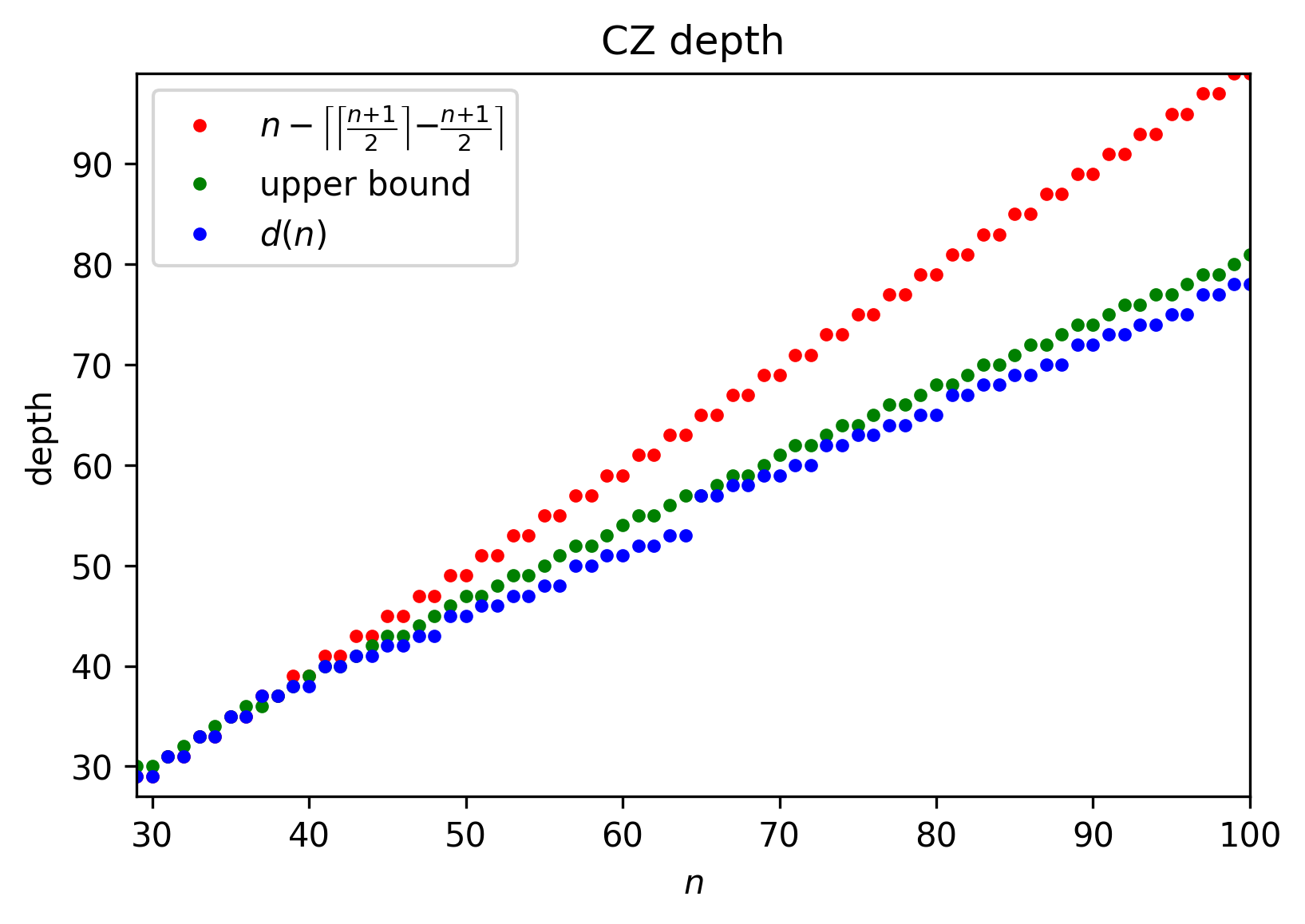
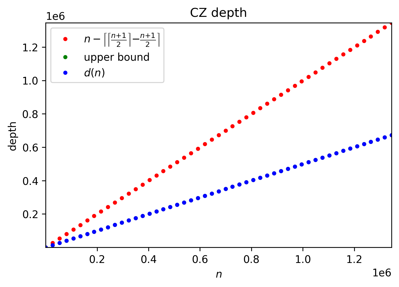
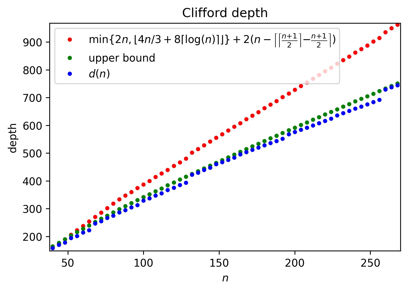
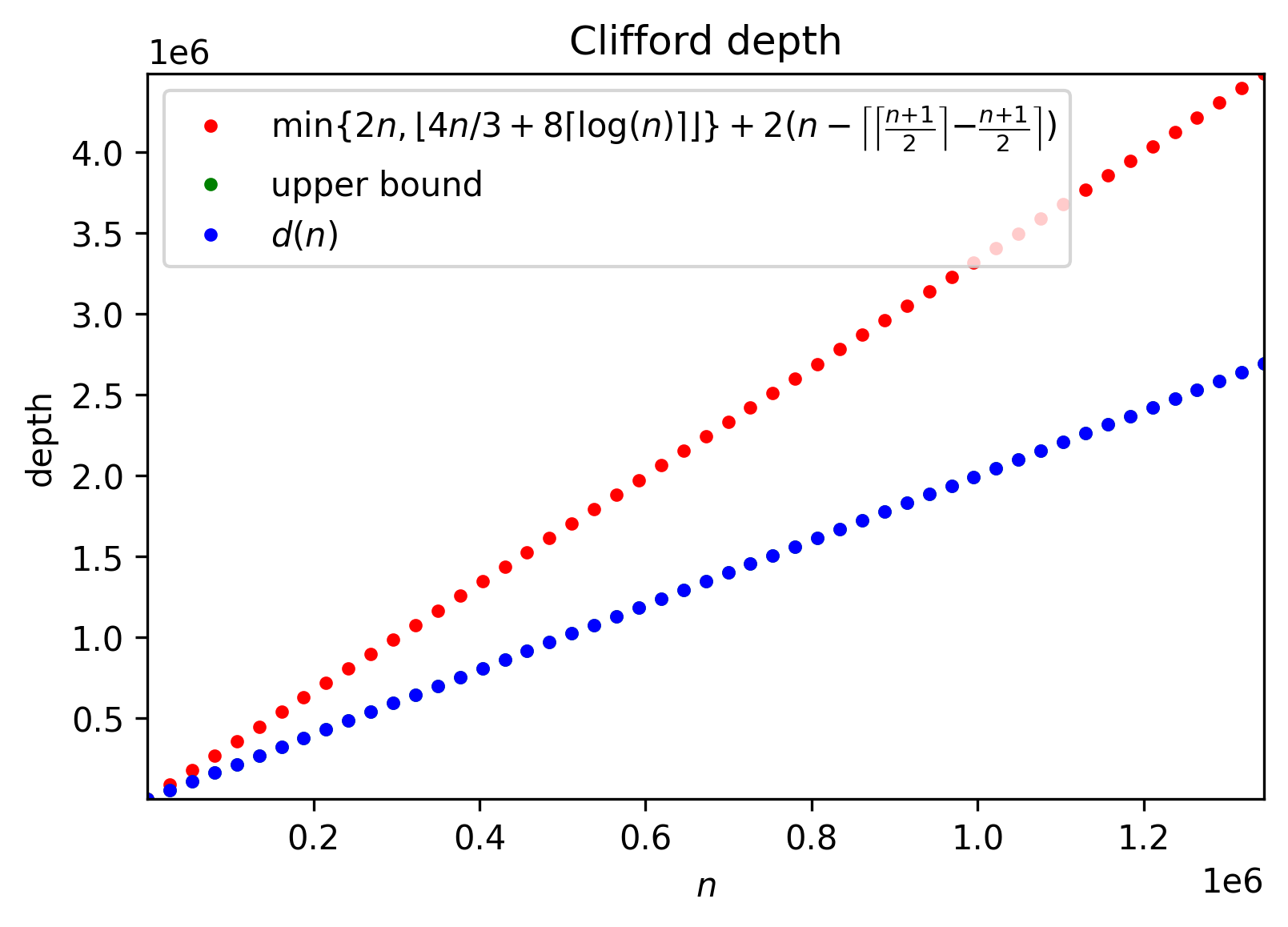
We illustrate the comparison of the best previously known bound on the depth of CZ circuits to the exact solution of the recursion Eq. (3) and the upper bound given in Theorem 1 in Figure 2. Note that the exact solution of the recursion Eq. (3) gives slightly lower numbers than those made available by the upper bound. This is because the discrete operations ceiling and floor are not easy to model by continuous functions used in the formulation of the upper bound. At the full scale, see Figure 2(b), the difference between exact solution and the upper bound given is visually undetectable, and our result can be seen to improve the best known previously roughly by a factor of two (therefore, agreeing with the asymptotics).
 |
 |
| (a) | (b) |
2.2 CNOT circuits
 |
 |
| (a) | (b) |
Here we extend the construction of depth-efficient CZ circuits to obtain depth-efficient implementations of linear reversible circuits. A linear reversible function can be implemented exactly or up to the SWAPping of output qubits, also known as qubit reordering. An implementation up to qubit reordering may be preferred since the proper qubit SWAPping may be obtained classically, allowing to outsource this task to a classical computer and thus minimize the expensive quantum resources used. The following Lemma reports an optimized depth figure for linear reversible functions and highlights that a depth reduction by is possible to achieve if it suffices to implement the desired linear function up to qubit reordering.
Lemma 3.
For an -qubit linear reversible transformation can be implemented in depth no more than up to qubit reordering and depth exactly as a circuit over gates.
Proof.
We start with the LU decomposition , where is lower-triangular and is upper-triangular invertible Boolean matrices. Recall that the LU decomposition exists subject to proper row and/or column ordering. Such row/column reordering can be implemented as a SWAPping circuit with the SWAP depth of no more than , translating to the two-qubit gate depth (by those gates considered in this work as contributing to depth) of . Thus, the difference between the depths of implementations up to qubit reordering and the exact one is a constant equal to . In the following, we show that each and stage can be implemented in depth , and thus the total depth of CNOT circuits is upper bounded by the expression .
Without loss of generality, focus on . Divide the set of qubits into two, set with the first qubits and set with the last qubits (this assumes that the qubits are already ordered so as to accept the LU decomposition). The operation can be written as the block matrix product
| (4) |
where is the upper triangular matrix obtained by restricting to the set of qubits , is defined similarly, is the top right block of , and and are the identity and zero matrices of proper dimensions.
Assuming denotes the depth of the implementation of an n-qubit upper triangular matrix, first two terms in the decomposition Eq. (4) can be implemented in parallel, i.e. in depth . The third term can be implemented as the CNOT gate circuit where individual gates have targets in the qubit set and controls in the set . This transformation can thus be written as the circuit , where applies Hadamard gates to all qubits in the set , and is an CZ rectangle. By inducing the bipartite graph coloring argument, we conclude that the rectangle can be implemented in depth at most . This results in the recursion
| (5) |
The solution, , is almost equal to . For the range of values of interest, we can upper bound it as .
Note that the circuit constructed in Lemma 3 relies on the gates from the library . It is convenient to use this gate library for didactic reasons, however, the circuit constructed in Lemma 3 can be rewritten using the same number of entangling gates and the same depth, but relying on the CNOT gates only.
Proposition 1.
The circuit constructed in Lemma 3 can be implemented in the same depth and with the same entangling gate count as the original, but using only the CNOT gates.
Proof.
Given the division of the set of all qubits into two non-overlapping sets and , a two-qubit gate is called internal to a given set if both qubits it operates on belong to this set and straddling iff it operates over two qubits belonging to different sets. Clearly, all entangling gates in such circuit are either internal to one of the sets or straddling.
Choose the sets and from the proof of Lemma 3. Observe that we apply Hadamard gates to all qubits in the set in two layers. Between those two Hadamard gate layers, all internal gates are CNOT gates and all straddling gates are CZ gates. This means that we can push the left layer of Hadamard gates to the right layer to cancel both, while flipping controls and targets of some CNOT gates and turning CZ gates into CNOT gates using the following rules:
and
.
Observe that this operation, when applied recursively to the matching pairs of layers of Hadamards, eliminates all Hadamard gates and turns all CZ gates into CNOTs. Thus, the transformed circuit has only the CNOT gates. ∎
| = |
We illustrate the constructions in Lemma 3 and Proposition 1 with the following Example.
Example 1.
Consider the linear reversible transformation given by the Boolean matrix
A naïve algorithm focusing on depth optimization may implement this linear transformation in depth 7 by noticing that all off-diagonal ones with matrix indices over non-overlapping sets of qubits can be turned into zeroes by applying the CNOT gates with controls in the second half of the set of qubits and target in the first half. A tight schedule exists that squeezes all 49 such CNOT gates in depth .
A better circuit of depth 6 can be obtained by applying Lemma 3. First, observe that the matrix is already upper triangular and thus the LU decomposition needs not be developed. The set contains first qubits, to which the Hadamard gates are applied, and the set contains the remaining qubits. The matrix found in the first quadrant of gives rise to the all-1 CZ matrix, and thus the circuit for it can be obtained from Lemma 1. Recall that this circuit EXORs qubits in the sets and , applies CZ gates, and uncomputes the EXORs. All five stages (opening Hadamards, finding EXOR, applying CZ, uncomputing EXOR, closing Hadamards) are clearly visible in the resulting circuit illustrated in Figure 4 on the left side. The circuit on the right side of Figure 4 is obtained from the one on the left side by applying Proposition 1.
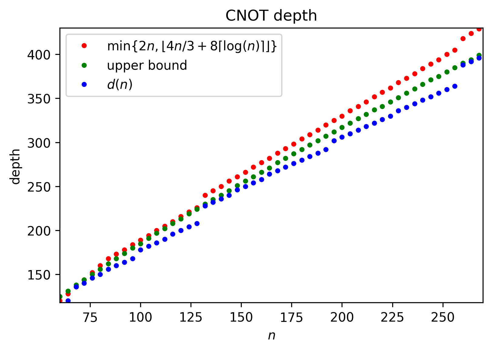
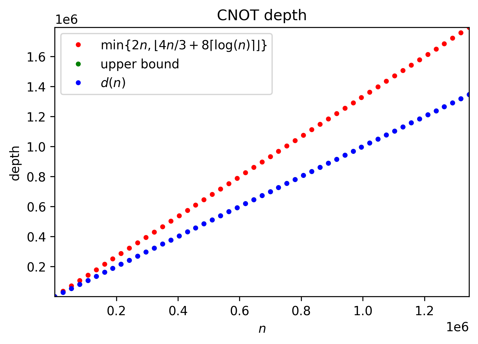
We conclude this subsection with the comparison of the depth of CNOT circuits developed in our work to the best known previously in Figure 3. Similarly to the analogous comparison for CZ circuits, small values of reveal a small difference between the exact solution and the upper bound (see Lemma 3), that is undetectable by eye over the full range (see Figure 3(b)). For values of in the target range, our result improves the best known previously by a factor of almost , as expected from the asymptotics.
2.3 Clifford circuits
Recall that a Clifford circuit admits the layered decomposition -X-Z-P-CX-CZ-H-CZ-H-P- [21]. Adding depths of the implementations of CZ circuits by Theorem 1 (two layers) and CNOT circuits by Lemma 3 (single layer), we obtain the following result. Note that one of the two -CZ- layers neighbors the -CX- layer, thus allowing to merge the CNOT gates used in the largest T-transformation with the -CX- stage; accounting for this results in the reduction of the depth by either or , depending on the first stage called by the recursion Eq. (3).
Lemma 4.
For an -qubit Clifford circuit can be implemented in depth
 |
 |
| (a) | (b) |
3 Conclusion
In this paper, we focused on the study of depth-reduced implementations of CZ gate quantum circuits spanning a practically relevant number of qubits , . The improvements in depth were accomplished by implementing CZ circuits over library rather than relying on the CZ gates alone. We extended the methods used to obtain better depth guarantees for CZ gate circuits to linear reversible and Clifford circuits. Asymptotic reductions on the CZ, CNOT, and Clifford circuit depths against state of the art proved in our work are by a factor of , , and , correspondingly.
References
- [1] T. G. de Brugière, M. Baboulin, B. Valiron, S. Martiel, and C. Allouche, “Reducing the depth of linear reversible quantum circuits,” IEEE Transactions on Quantum Engineering, vol. 2, pp. 1–22, 2021.
- [2] M. A. Nielsen and I. Chuang, Quantum Computation and Quantum Information. Cambridge University Press, 2002.
- [3] S. Bravyi and A. Kitaev, “Universal quantum computation with ideal Clifford gates and noisy ancillas,” Physical Review A, vol. 71, no. 2, p. 022316, 2005.
- [4] E. Knill, D. Leibfried, R. Reichle, J. Britton, R. B. Blakestad, J. D. Jost, C. Langer, R. Ozeri, S. Seidelin, and D. J. Wineland, “Randomized benchmarking of quantum gates,” Physical Review A, vol. 77, no. 1, p. 012307, 2008.
- [5] E. Magesan, J. M. Gambetta, and J. Emerson, “Scalable and robust randomized benchmarking of quantum processes,” Physical Review Letters, vol. 106, no. 18, p. 180504, 2011.
- [6] C. H. Bennett, D. P. DiVincenzo, J. A. Smolin, and W. K. Wootters, “Mixed-state entanglement and quantum error correction,” Physical Review A, vol. 54, no. 5, p. 3824, 1996.
- [7] S. Aaronson, “Shadow tomography of quantum states,” in Proceedings of the 50th Annual ACM SIGACT Symposium on Theory of Computing, ser. STOC 2018. New York, NY, USA: Association for Computing Machinery, 2018, p. 325–338.
- [8] S. Bravyi, J. A. Latone, and D. Maslov, “6-qubit optimal Clifford circuits,” npj Quantum Information, vol. 8, no. 1, pp. 1–12, 2022.
- [9] S. Aaronson and D. Gottesman, “Improved simulation of stabilizer circuits,” Physical Review A, vol. 70, no. 5, p. 052328, 2004.
- [10] K. N. Patel, I. L. Markov, and J. P. Hayes, “Optimal synthesis of linear reversible circuits,” Quantum Information and Computation, vol. 8, no. 3, p. 282–294, 2008.
- [11] J. Jiang, X. Sun, S.-H. Teng, B. Wu, K. Wu, and J. Zhang, “Optimal space-depth trade-off of CNOT circuits in quantum logic synthesis,” in Proceedings of the Fourteenth Annual ACM-SIAM Symposium on Discrete Algorithms, 2020, pp. 213–229.
- [12] S. A. Kutin, D. P. Moulton, and L. M. Smithline, “Computation at a distance,” arXiv preprint quant-ph/0701194, 2007.
- [13] E. T. Campbell, B. M. Terhal, and C. Vuillot, “Roads towards fault-tolerant universal quantum computation,” Nature, vol. 549, no. 7671, pp. 172–179, 2017.
- [14] E. Pednault, J. A. Gunnels, G. Nannicini, L. Horesh, and R. Wisnieff, “Leveraging secondary storage to simulate deep 54-qubit sycamore circuits,” arXiv preprint arXiv:1910.09534, 2019.
- [15] Y. Nam and D. Maslov, “Low-cost quantum circuits for classically intractable instances of the Hamiltonian dynamics simulation problem,” npj Quantum Information, vol. 5, no. 1, pp. 1–8, 2019.
- [16] M. Reiher, N. Wiebe, K. M. Svore, D. Wecker, and M. Troyer, “Elucidating reaction mechanisms on quantum computers,” Proceedings of the National Academy of Sciences, vol. 114, no. 29, pp. 7555–7560, 2017.
- [17] S. Beauregard, “Circuit for Shor’s algorithm using 2n+3 qubits,” arXiv preprint quant-ph/0205095, 2002.
- [18] C. Gidney and M. Ekerå, “How to factor 2048 bit RSA integers in 8 hours using 20 million noisy qubits,” Quantum, vol. 5, p. 433, 2021.
- [19] IBM Quantum, “IBM Quantum Experience,” https://quantum-computing.ibm.com/, 2022.
- [20] S. Debnath, N. M. Linke, C. Figgatt, K. A. Landsman, K. Wright, and C. Monroe, “Demonstration of a small programmable quantum computer with atomic qubits,” Nature, vol. 536, no. 7614, pp. 63–66, 2016.
- [21] S. Bravyi and D. Maslov, “Hadamard-free circuits expose the structure of the Clifford group,” IEEE Transactions on Information Theory, vol. 67, no. 7, p. 4546–4563, Jul 2021.
- [22] V. G. Vizing, “On an estimate of the chromatic class of a p-graph,” Discret Analiz, vol. 3, pp. 25–30, 1964.
- [23] R. Cole and J. Hopcroft, “On edge coloring bipartite graphs,” SIAM Journal on Computing, vol. 11, no. 3, pp. 540–546, 1982.