Response to Reviewers’ Comments
Title: Millimeter Wave Wireless Assisted Robot Navigation with Link State Classification
Dear Reviewers and Editor,
We thank you for taking the time to provide an insightful critique of our work and greatly appreciate the constructive feedback. We agree with most of the comments/suggestions and have tried to incorporate them as best as possible. In the process, we believe that the quality of the manuscript has improved greatly. The significantly modified parts to the manuscript are in red ink. Our response to your comments are included inline below. To avoid confusion between equations/figures/tables in this document and the paper, we index using uppercase roman letters here (e.g., Fig. A, Table A, and so on). We hope that we have been able to satisfactorily address all the issues that were raised.
Regards,
Mingsheng Yin, Akshaj Kumar Veldanda, Amee Trivedi, Jeff Zhang,
Kai Pfeiffer, Yaqi Hu,
Siddharth Garg, Elza Erkip, Ludovic Righetti, Sundeep Rangan
Major Changes
Before we address the specific comments of the reviewers, we would like to note some broader changes we have made to the manuscript based on the reviewers’ suggestions. We believe these new features significantly improves the results:
-
•
Comparison to baseline algorithms for navigation: Several reviewers requested we compare our results more extensively with prior results. The difficulty was that the navigation problem itself here is new, and this problem was part of the contribution. Prior results where one must find a target from mmWave wireless and visual information in an unknown environment has not been studied.
That being said, we can evaluate the potential benefit of wireless information by comparing the proposed “AoA when LOS or First-order NLOS” algorithm, against a state-of-the-art completely computer vision based navigation algorithm, that we call “Visual LOS only” algorithm. As explained in the new manuscript, in the Visual LOS only algorithm, the robot first uses the state-of-the-art Active Neural-SLAM algorithm [chaplot2020learning] to explore the unknown environment. As soon as the target appears in the robot’s field of view, we assume that the robot will use a computer vision technology to identify and locate the target with 100% accuracy, and then finally the robot sets the goal on the position of the target and navigates itself. Since the Active Neural-SLAM algorithm has been demonstrated to be one of the most powerful SLAM methods, and we are assuming perfect target detection in Visual LOS, the baseline “Visual LOS only” algorithm provides a strong benchmark against which we can compare the proposed wireless solution.
Remarkably, as explained in the manuscript, the proposed wireless localization algorithm outperforms Visual LOS only, even with optimistic assumptions on visual LOS. These results suggest that mmWave wireless – when used correctly – can significantly reduce target localilization time.
For example, Table. A shows the proposed “AoA when LOS or First-order NLOS” wireless assisted algorithm has an absolute advantage in both the hard and moderate level tests. The state-of-the-art computer vision based “Visual LOS SLAM” algorithm has an advantage only on the first quartile and median number in the easy level tests. In the Table. A, “Q1” denotes the first quartile, “median” denotes the second quartile, “Q3” denotes the third quartile, and “Upper Fence” represents the cut-off values for upper outliers in the tests. The lower value is better, and we use the yellow color to highlight the best values in the columns.
TABLE A: Table of Statistical Results Speed Based on Baseline (Lower is Better) Difficult Level Hard (65 tests) Moderate (76 tests) Easy (52 tests) Satistics Value Q1 Mediam Q3 Upper Fence Q1 Mediam Q3 Upper Fence Q1 Mediam Q3 Upper Fence AoA when LOS or First-order NLOS 1.52 2.17 2.84 4.43 1.81 2.19 2.90 4.16 1.05 1.38 1.65 2.54 AoA when LOS 1.77 2.62 4.80 7.01 1.73 2.36 4.49 8.38 1.09 1.46 1.69 2.46 AoA Based on SNR without Prevent Stock 1.78 2.55 8.84 9.09 1.87 2.22 2.98 3.73 1.09 1.44 1.67 2.55 Visual LOS (CV-Based SLAM) 1.70 2.62 6.42 11.43 1.30 2.54 5.61 11.68 1.01 1.13 2.30 3.84 Fig. A shows the arrival rate of different algorithms. The “successful reach” is defined as the robot can reach the target within the limit of 1000 moving-steps, and for a algorithm, the higher rate is better. It is clear that the proposed four-way link-state classification “AoA when LOS or First-order NLOS” wireless assisted algorithm beats the state-of-the-art computer-vision based “Visual LOS” algorithm in all three difficult levels.
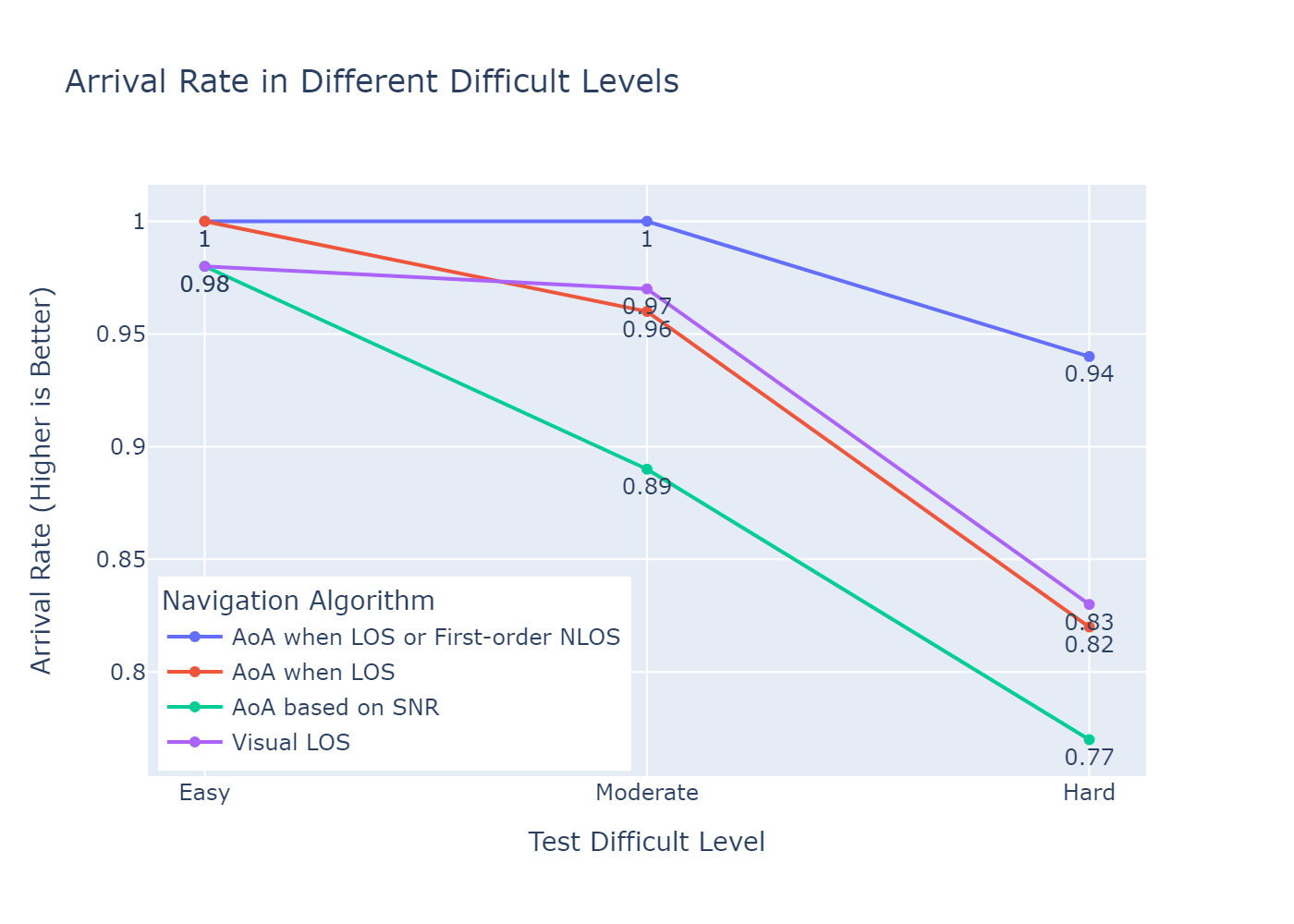
Figure A: Arrival Rates (higher is better) Fig. B shows the CDFs of the arrival speed of different navigation algorithms. It is evident that the proposed four-way link-state classification “AoA when LOS or First-order NLOS” wireless assisted algorithm is more efficient and stable. The CDF curves clearly demonstrate that the state-of-the-art computer vision based “Visual LOS” navigation algorithm does not perform well in part of hard and moderate level tests.
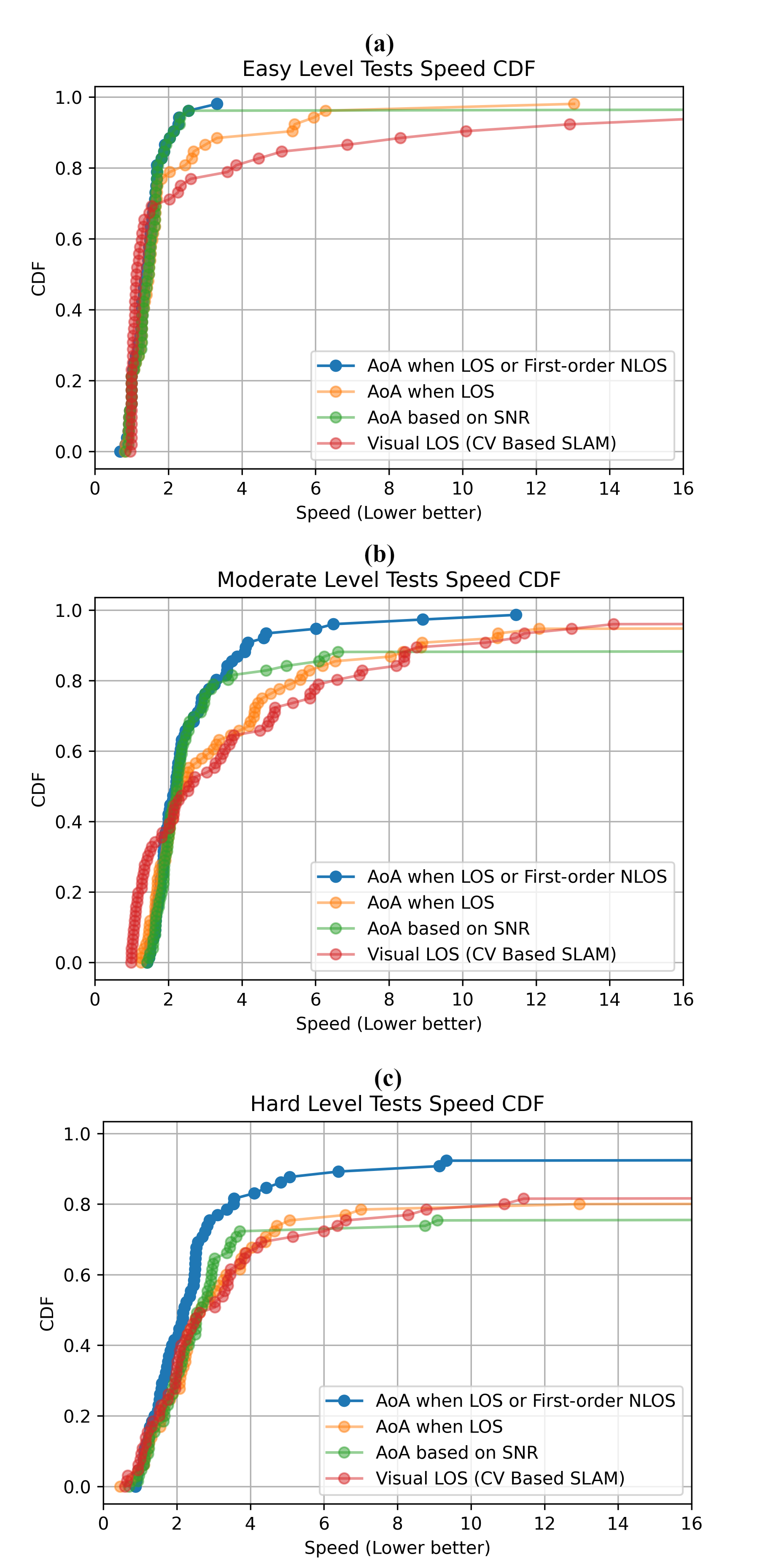
Figure B: Arrival Speed CDFs (lower is better) Many of the above results are in the new manuscript.
-
•
Comparison to prior algorithms for link state detection. Similar to the case of navigation, several reviewers requested that we provide better comparison to the prior algorithms for link state detection. As we point out in the paper, the particular link-state detection problem we are considering is new since prior works do not generally distinguish between first order NLOS and high order NLOS. Nevertheless, we now compare our neural network method to a modified method from [huang2020machine], one of the best prior work algorithms in LOS-NLOS detection. The method of [huang2020machine] uses a set of custom features, while our proposed approach uses the raw MPC (the multipath component) data. As shown in the new results, our current method outperforms this modification of the prior method (our method obtains 88% accuracy while the prior method obtains 84%, as shown in Fig. C, D, and E). Of course, the main contribution in our work is consideration of first-order vs. higher-order NLOS, not this accuracy gain. But, we now include the discussion of the accuracy gain as well for completeness. See details in the manuscript.
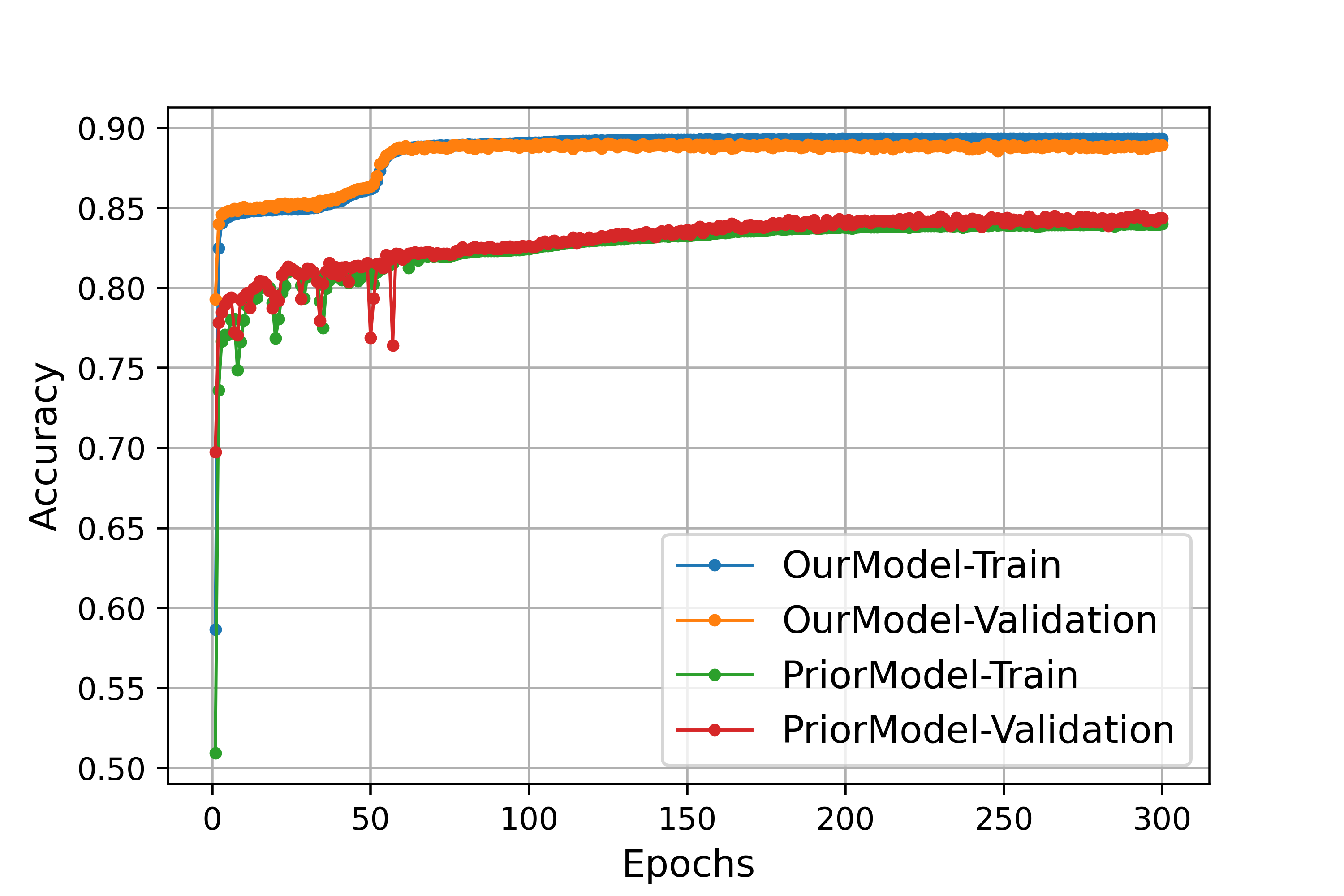
Figure C: Training and Validation Accuracy of Two Models 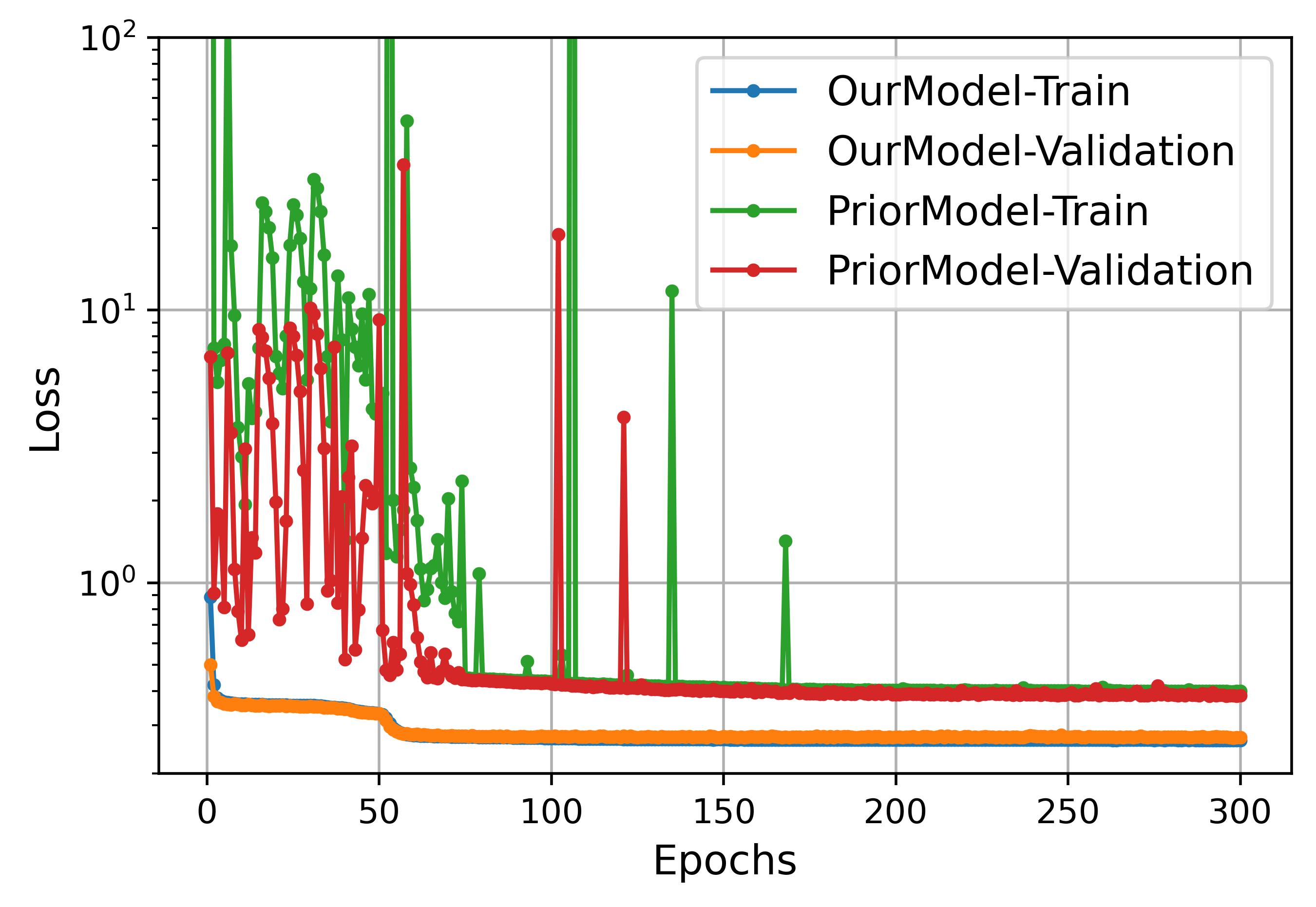
Figure D: Training and Validation Loss of Two Models 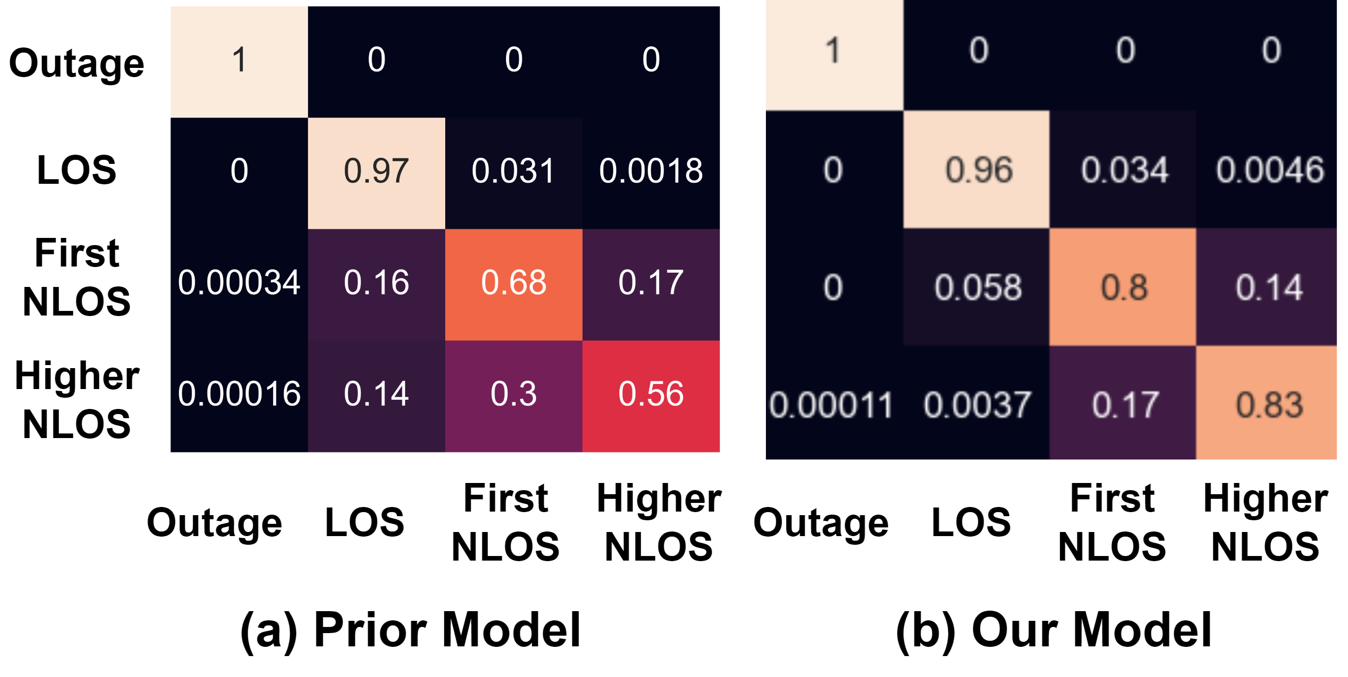
Figure E: Confusion Matrices of Two Models
Reviews 1 (Reviewer 1)
Detailed comments
-
1.
The reviewer would like the authors to highlight their novelty and contributions. It seems that the proposed procedure is cobbled from some existing techniques, e.g. path estimation via low-rank tensor decomposition, link state classification. See also Comment 2.
Response: This was a good suggestion to highlight the novelty. As explained in the new manuscript, first, and most importantly, the problem itself is new. Prior works had not considered the case of localizing a target with both mmWave and visual information in an unknown environment. Also, while the components were known, they had not been used together in this manner. Moreover, each of these components required modifications for the problem at hand. For example, the tensor decomposition needed to be modified for the directional antenna elements, multiple arrays, and beam sweeping. The link state classification needed to distinguish between first ordrer and high order LOS and also be trained on ray tracing data. The navigation needed to carefully combine the wireless information with the state of the art exploration tools.
In the introduction, the authors said, ”The proposed method and analysis has a number of features that improve upon the state of the art.” But no results are compared in the simulation results. Is it possible to add some state-of-the-art comparison in the simulation results?
Response: This was an important comment. See the Major Changes section above for the changes we have made to provide comparisons for both the navigation and link state classification.
-
2.
P.8.col R line 42, ”AOA” should be ”AoA”, make sure all the abbreviations is consistent.
Response: Thank you for pointing is out. We have fixed them in the revised manuscript.
Reviews 2 (Reviewer 2)
Detailed Comments
-
1.
The academic writing can be further improved, as some typos and grammar mistakes are found. Some sentences are also misleading, which may cause difficulty for readers. Here are part of the comments:
-‘A three stage procedure’ should be ‘A three-stage procedure’
-‘A target has a wireless transponder and a robotic agent’ should be ‘A target with a wireless transponder and a robotic agent’
Response: Thank you for pointing these out. We have fixed them in the revised manuscript.
-
2.
The author is suggested to rewrite the abstract if the manuscript get accepted. In general, the abstract helps in understanding the main idea of the manuscript. However, the reviewer has to read the whole manuscript to understand this abstract.
- In abstract, ’a mobile robotic agent attempts to listen to the signals’, the verb ‘listen’ is not appropriate, maybe use ’capture’ or ’receive’
- In abstract, ‘to detect the wireless paths and their angles.’ What is the term ‘wireless paths’ indicates? Do you mean ’to detect the existence of multipath as well as their incept angle ’
Again, the ‘the agent either follows the estimated angles or explores the environment.’ This sentence is also confusing. Based on your contents, the link state predictor should present the visibility of the LoS path, or how many order of reflections that the multipath required. So what means ‘explores the environment’? The estimated incepted angle of the strongest multipath?
Response: Thank you for your suggestions. We have clarified all these terms in the new abstract. In particular, we have followed your suggestion of “capture” instead of “listen to.” Regarding the ’detecting wireless paths and their angles’, you are correct that we mean detecting the existence of multi-path components and their parameters such as gain, angles of departure, delay, and angles of arrival. We have also elaborated more on what we mean by “explore the environment”.
-
3.
‘Positioning measurements in the mmWave range have several unique aspects’. Aspects? Do you mean ‘features? Also, features of ‘Positioning measurements in the mmWave range’ should be listed and explained since you already mentioned.
Response: Yes, we meant ”features”. We have changed the manuscript to list those features.
-
4.
The author considers multipath in four states, which is acceptable. However, how do you separate the ‘First-order NLOS’ and the ‘Higher-order NLOS’ based on your definition?
Response:
 Figure F: A demonstration of the LOS, Higher-order NLOS,
and Higher-order NLOS.
If the question here is about clarifying the definition of first order vs. high-order LOS, we have modified the manuscript to make the distinction more clear (see Section II.A and the included figure, Fig. F above).
If the question is how a neural network can distinguish first-order vs. higher-order LOS so accurately, we agree: this finding is indeed interesting. Of course, from a single multi-path component, one cannot know if it arrived via one or more reflections. However, the neural network demonstrates that the joint statistics across multiple path components can reveal the number of reflections with a high accuracy in completely new environments not part of the training data set.
-
5.
For the channel model in equation 7, what is the angle of Rx and Tx? Moreover, the steering vector matrix describes the array manifold of an array configuration, so why the two steering vector matrixes in your channel model are multiplied together? Can you please explain?
Response: As normal, we write the RX array signature as a function of the RX angle of arrival of a plane wave. In this study, there are multiple arrays. So, each array will have an array signature and we use the notation to the denote the combined array signature across all the arrays. The notation is similar. We have modified the text to make this more clear.
Reviews 3 (Reviewer 3)
Detailed Comments
-
1.
As the robot does not need to know the environment, training the neural network will require sometime and it might delay the output in some scenarios such as fire or safety applications?
Response: This is an excellent question. As described in the Section IV of the manuscript, there are a total of 38 different environments. We train on 18 of them, and test on 20. Thus, the robotic agent is operating with a pre-trained network in a completely new environment. No new training is required in the new environment. The manuscript now includes more explanations of how the pre-train model works.
-
2.
Mm-Wave will employ low power transceivers. How are we meant to resolve multiple paths with limited power, this issue looks like an ultrawide bandwidth case where different authors have tried to address this issue. It would be nice to add a paragraph on UWB localisation and help differentiate mm-Wave with UWB.
Response: Thanks for pointing this out. It is true that UWB is widely using in the indoor localization applications, and we add [zwirello2012uwb, zhang2008high], and comment them in the manuscript. As we mentioned, a key difference with UWB is that while UWB allows very high temporal resolution (due to the wide bandwidth), mmWave uniquely allows high angular resolution due to the large antenna arrays. Regarding power levels, we assumed typical values (e.g. 23 dBm) assumed in most studies of commercial smart phones.
-
3.
Why paths are assumed, and the strongest path with the highest SNR is used. It might be that the received strongest path is a reflection from the previous path.
Response: This is a good question. In general, increasing the number of paths increases the number of features in our model and hence can result in over-fitting. We found to provide the lowest generalization error. We now mention it in this manuscript. Note that we take the strongest paths, not the earliest paths. Hence, we do not miss any strong paths that arrive late, if that is your question.
-
4.
Link state Classification Neural Network are not clearly explained.
Response: Thanks for pointing this out. In this paper, we consider each “Transmitter-Receiver” link including multiple paths, and in section II (A) of the paper, we describe four link-states: LOS, first-order NLOS, higher-order NLOS, and outage. The link-state of the wireless channel may change as the robot navigates in an unknown environment. The input of the link-state classification neural network is defined in equation 16:
where (as explained in the last question), is the path SNR, and are the angle of arrival and the angle of departure, and the is the path delay. The link-state classification neural network provides the probabilities of the four link-states for the channel that the robot is currently connected to.
The technical details of this classification network can be found in Table B, which also can be found in paper Section V-C. This network has two dense layers. The size of inputs is 20 (when ) and the size of output is 4 (the probabilities of link-states). In the revised manuscript, we have revised some of the expositions to explain the link-state classification neural network more clearly.
TABLE B: Link state neural network classifier configuration Parameter Value Number of inputs 20 Hidden units [8, 6] Number of outputs 4 Optimizer Adam Learning rate 0.001 Epochs 200 Batch size 1024 -
5.
Figure 9 needs to be explained in more detail.
Response: Thanks for your comment, and we add more explanations about Figure 9 in manuscript.
-
6.
Compare the work with relevant work in this area.
Response: This is very good comment, and we add two parts in the new manuscript to compare the work with relevant work: comparison to baseline algorithms for navigation, and comparison to prior algorithms for link state detection. Please check the “Major Changes” section above.
-
7.
In abstract the author claims that the link state classifier can be successfully generalized to new environments. The claim is not right.
Response: This is a good comment. In the response of reviews 3 comment 1, we discussed how we train the link-state classifier in 18 maps and the robot uses the pre-trained link state classifier to test different navigation algorithms in the other 20 maps. It should be noted that the pre-trained network is not trained using the maps that we use during testing. Furthermore, the navigation test maps are completely unknown environments for the robot, thus the robot with the link state classifier is used in the new indoor environments. The manuscript’s Section VI-C presents the results that were obtained when the robot with a pre-trained link state classifier (trained in 18 maps) was used in the other 20 different maps. In this case, the results already show that our pre-trained link state classifier can be successfully generalized to new environments. In the revised manuscript, we have revised some of the expositions to explain the pre-trained link-state classification neural network more clearly.