Shape multistability in flexible tubular crystals through interactions of mobile dislocations
Abstract
We study avenues to shape multistability and shape-morphing in flexible crystalline membranes of cylindrical topology, enabled by glide mobility of dislocations. Using computational modeling, we obtain states of mechanical equilibrium presenting a wide variety of tubular crystal deformation geometries, due to an interplay of effective defect interactions with out-of-tangent-plane deformations that reorient the tube axis. Importantly, this interplay often stabilizes defect configurations quite distinct from those predicted for a two-dimensional crystal confined to the surface of a rigid cylinder. We find that relative and absolute stability of competing states depend strongly on control parameters such as bending rigidity, applied stress, and spontaneous curvature. Using stable dislocation pair arrangements as building blocks, we demonstrate that targeted macroscopic three-dimensional conformations of thin crystalline tubes can be programmed by imposing certain sparse patterns of defects. Our findings reveal a broad design space for controllable and reconfigurable colloidal tube geometries, with potential relevance also to carbon nanotubes and microtubules.
I Introduction
Diverse biological and synthetic systems at a range of scales are self-organized in ordered two-dimensional assemblies of cylindrical topology, including single-walled carbon nanotubes (SWCNTs) thess1996crystalline , filamentous viral capsids klug1999tobacco , microtubules (MTs) nogales2001structural and colloidal systems tymczenko2008colloidal . Such tubular crystals frequently have circumferences of order only ten times the interparticle spacing. This has the important consequence of restricting the orientations of the crystal axes, which trace out helical paths called parastichies, to a discrete set of possible angles with the tube axis. The number of distinct parastichies defines a pair of integer parastichy numbers, which index the possible crystalline tessellations of the cylinder, and which for SWCNTs determine the nanotube’s electrical conductivity yakobson1998mechanical . The “parastichy” terminology arises from an intriguing connection with the botanical study of phyllotaxis, which examines plant structures with repeating patterns that follow parallel helices (or spirals); examples include the arrangements of seeds on a pine cone, scales on a pineapple, or leaves on a stem adler1997history ; pennybacker2015phyllotaxis .
Along with the importance of tubular crystals to molecular biology and the study of 2D solids, there is a growing interest in tubular crystals among soft matter physicists, due to the potential for exploiting phyllotaxis as a self-organization principle for colloidal particles or nanoparticles, and thus for creating assemblies of controllable helical pitch and chirality li2005fabrication ; tymczenko2008colloidal ; sadoc2012phyllotaxis ; avan2020self ; li2019self . Higher-scale organization can occur through the coexistence of distinct phyllotactic tessellations on the same tube lohr2010helical . Topological defects are central to this higher-scale organization: a change in parastichy numbers requires one or more dislocation defects at the boundary between domains harris1980tubular . In SWCNTs, the analogous Stone-Wales defects in the honeycomb lattice of graphene are of great interest for their influence on plastic deformations and electrical conductivity yakobson1998mechanical . Similarly, the observation of microtubules with varying protofilament number (i.e. circumference) along their length implies the presence of dislocations in the rhombic packing of tubulin proteins chretien1992lattice .
Much of the recent work on frustrated phyllotactic self-organization has focused on particles constrained to lie in a fixed cylindrical surface mughal2011phyllotactic ; wood2013self ; mughal2014theory ; fu2016hard . That version of the tubular crystal is realized in recent experiments on colloids in capillary confinement moon2004fabrication ; li2005fabrication ; tymczenko2008colloidal as well as a macroscopic “magnetic cactus” model nisoli2009static ; nisoli2010annealing , and it gives rise to a rich variety of phenomena such as oblique (rhombic) lattices, helical faults known as line slips, and individual dislocations behaving analogously to infinite grain boundaries Amir13 .
However, in order to design colloidal analogues of MTs and SWCNTs, we must examine a different version of the problem, namely the freestanding tubular crystal. Here, the particles are not constrained to any fixed surface; instead, the tubular surface emerges as the set of mechanical equilibrium positions of particles whose bond network has the topology of a tube BellerPRE16 . The ability of the tube shape to adapt locally and dynamically removes the source of frustration, namely the fixed circumference, that underlies the rich defect phenomenology of the fixed-cylinder crystals. On the other hand, this geometrical adaptability offers potential routes to stabilizing nontrivial tube shapes in the presence of defects, a possibility that has remained mostly unexplored.
In this work we demonstrate numerically that freestanding tubular crystals possess controllable and composable mechanically multistable geometries, enabled by rearrangements of dislocations through glide mobility. This effect, which we refer to as “dislocation-mediated shape multistability,” operates through a newly identified co-stabilization of kinks in the tube axis with defect configurations that would be unstable on the fixed cylinder or the plane. While such kinks can also be formed with isolated disclinations dunlap1994constraints ; bowick2009two , our focus on dislocation pairs emphasizes mechanical shape-reconfigurability through dislocation glide moves, which are purely local disruptions in the lattice.
Using a minimal model of a tubular crystalline membrane, we show not only that a tubular crystal may possess distinct, mechanically stable geometries, but also that it is possible to controllably switch between these competing states. Such switching can be achieved through quantitative changes in material properties, which in principle might be accomplished in situ by varying the temperature, or through application of external bending forces in a reversible shape-memory effect. Furthermore, by repeating certain stable dislocation motifs along the length of a tubular crystal, we show how multiple-kink structures approximating arbitrary curves can be targeted as equilibrium geometries, offering proofs of principle for large-scale shape manipulations of tubes into bent and helical structures.
The important distinction between freestanding and fixed-surface crystals is well-known for the spherical topology, providing the difference between the scars of “spherical crystallography” bausch2003grain on rigid spheres and buckled crystalline shells resembling viral capsids lidmar2003virus in flexible membranes. More generally, ordered soft matter confined to rigid, curved surfaces tends to relax the stresses imposed by Gaussian curvature through pair-nucleation of topological defects bowick2009two ; vitelli2006crystallography ; ellis2018curvature ; conversely, freestanding crystalline membranes can spontaneously adopt buckled geometries in the presence of defects such as dislocations and disclinations seung1988defects ; zhang2014defects . An analogous effect in nematic elastomer sheets allows for targeted shape transitions in the vicinity of a topological defect modes2011gaussian ; zakharov2015reshaping , where non-zero Gaussian curvature arises to relax the elastic stresses.
At the same time, it is worth emphasizing key differences between tubular and spherical crystals. For spheres, topology demands a net excess disclination charge of +2, whereas tubes (even if closed as a torus) have no topologically required defects. In addition, the Gaussian curvature of surfaces such as spheres and tori can promote lines of dislocations known as scars bausch2003grain and stabilization of excess unbound disclinations giomi2008elastic . In contrast, the Gaussian curvature in a perfect cylinder is everywhere zero. Rather, defects in a tubular crystal are intimately related with the discretization of crystal axes orientations: a change of parastichy numbers, whether occurring spontaneously or to mediate plastic deformation, necessarily requires an intervening dislocation.
We study the emergent interplay of dislocation interactions and surface deformation geometries by modeling the crystalline membrane as a triangular-lattice network of harmonic spring bonds with a bending rigidity, and with the overall topology of a tube. We assume that dislocations glide freely into energy-minimizing configurations, with a rapid relaxation of the crystal’s elastic energy between glide steps, and with a small, finite temperature able to overcome the Peierls barrier, which we ignore hirth1983theory ; BellerPRE16 . We prohibit climb motion for simplicity, with the justification that climb requires an exchange of mass with the surrounding medium along with breaking and forming of multiple bonds, a process typically much slower than glide relaxation hirth1983theory . By this means we calculate effective energy landscapes for dislocations interacting on a tubular crystal whose surface deformations respond strongly to changes in defect position, creating multistable energy landscapes in both defect configuration and tube shape.
Our approach extends the methodology widely used to create soft elastic actuators by encoding locally preferred membrane geometries in the in-surface order to develop target three-dimensional morphologies klein2007shaping ; gladman2016biomimetic ; aharoni2018universal . Our findings extend our understanding of the mechanism behind the large deformations in tubular crystals occurring in nature brangwynne2007force . Defects in the tubulin lattice can significantly alter the mesoscale shape of the MT, and can provide a means of plastic deformation to accommodate external stress without breaking janke2017causes or folding hunyadi2007microtubule or even reinforce the structure witten2007stress .
II Minimal model of a freestanding tubular crystal
We model the tubular crystal as a network of harmonic spring bonds , connecting massless nodes , with a bending rigidity , that penalizes deviations of the mesh from the preferred curvature. The network is six-coordinated, making a triangular lattice, everywhere except at elementary dislocations, where a five-coordinated positive disclination is adjacent to a seven-coordinated negative disclination. The discrete elastic energy associated with the stretching and bending of the mesh is defined as
| (1) |
The first term assigns a spring constant to deviations of bond length from rest length . The second term assigns the bending rigidity to curvature distortions calculated from the discrete mean curvature and discrete Gaussian curvature at each node (see Appendix A for details).
This free energy could represent a discretization of a continuum, isotropic elastic free energy (Eq. B1 in Appendix B) for a membrane with Young’s modulus , Poisson ratio , and Lamé coefficients . However, throughout this work we treat the nodes of the mesh as the inherently discrete particles that make up the phyllotactic tessellation. From Eq. 1, along with the proportionality of to and the tube radius , we obtain two important dimensionless parameters: the Föppl-von Kármán number , and the reduced bending rigidity .

The possible triangular lattice tessellations of a (quasi)-cylindrical surface can be conveniently indexed using the botanically-inspired parastichy numbers, a pair of integers defining the number of distinct helices of particles in the steepest right-handed and steepest left-handed families, respectively, with the former family making an angle with the tube axis (Fig. 1). Conventionally a third parastichy number , determined by the other two, is often included erickson1973tubular . For a pristine (defect-free) tubular crystal, the radius in the limit of small is uniform throughout the tube and is given by
| (2) |
However, for tubular crystals with defects, the tube radius is non-uniform, and we calculate a local at each node as the distance from a computed centerline (see Appendix E for details).
We consider elementary dislocations, each characterized by a Burgers vector , which has length and is oriented orthogonally to the bond connecting the 5-7 disclination pair landau_elasticity and parallel to one of the three parastichies passing through the dislocation site The parastichy numbers thus define six possible orientations for , each making a fixed angle , with the tube axis.
We examine stability of dislocation positions with respect to glide motion, which carries a dislocation parallel to along one of the helical parastichies in discrete steps of size . Dislocations with collinear Burgers vectors may sit on different parastichies, separated by climb motion normal to . Thus, in general, we can use the number of glide steps and climb steps separating the two parallel dislocations to parametrize axial separation and azimuthal separation for a , defect pair with orientations , (Fig. 1).
In this work we choose a few representative tessellations to explore in detail. Motivated by studies of microtubules, which are tubular rhombic crystals of tubulin proteins most often comprising 13 protofilaments schaedel2019lattice , we consider defects in tubular crystals with similar ratios of circumference to bond length: the zigzag achiral configuration , and the armchair achiral configuration . Our methods and qualitative findings can be extended to tubular crystals with other chirality, radius, or even lattice symmetry plummer2020buckling , presenting a broad design space for future investigations. In this work, we use our representative tubular crystals as test beds for a systematic construction of stable tube deformation geometries built up from dislocation pair interactions.
III Kinked tubes and multistability in defect pair-interactions
We begin by examining stable configurations containing two interacting dislocations; these configurations will then be used as basic building blocks for more complex geometries. For simplicity we choose the two Burgers vectors to be antiparallel to each other, , so that a Burgers circuit enclosing both defects measures a vanishing total Burgers vector. The effective interaction energy of the dislocation pair depends on the separation along the cylinder axis and the azimuthal direction, respectively, and on the Burgers vector inclination angles , relative the cylinder axis. Dislocations initialized on the same glide parastichy may pair-annihilate on reaching zero separation, , leaving a defect-free lattice at the energy minimum. This cannot occur for dislocations on different glide parastichies because climb would be needed to achieve zero separation.
While an analytical treatment of defects in freestanding tubular crystals is beyond the scope of this work, we turn to analytical predictions for the fixed-cylinder case as a point of comparison Amir13 . For general separations of a dislocation pair on a fixed-cylinder tubular crystal, integration of the defects’ stresses gives an effective interaction energy Amir13 ; BellerPRE16
| (3) |
where are dimensionless quantities. Although this expression comes from a continuum elasticity calculation, it was found to agree well with simulations of fairly small cylindrical crystals Amir13 . However, the fixed-cylinder case described by Eq. 3 has strictly zero Gaussian curvature and prohibits changes in tube radius that are energetically preferred when the phyllotactic indices change on either side of a dislocation, in accordance with Eq. 2. In contrast, as we show below, a freestanding tubular crystal partially screens this interaction energy by kinking at the dislocation sites, resulting in defect pair-interaction landscapes that can differ qualitatively from the fixed-cylinder prediction of Eq. 3. It is also noteworthy that Eq. 3 is even in , a symmetry that we will see is broken by the freestanding tube. We can expect to find significant deviations from Eq. 3 at defect separations on the order of , which is the length scale over which surface deformations from one dislocation can influence the other dislocation BellerPRE16 .
| (a) | (b) |
|---|---|
 |
 |
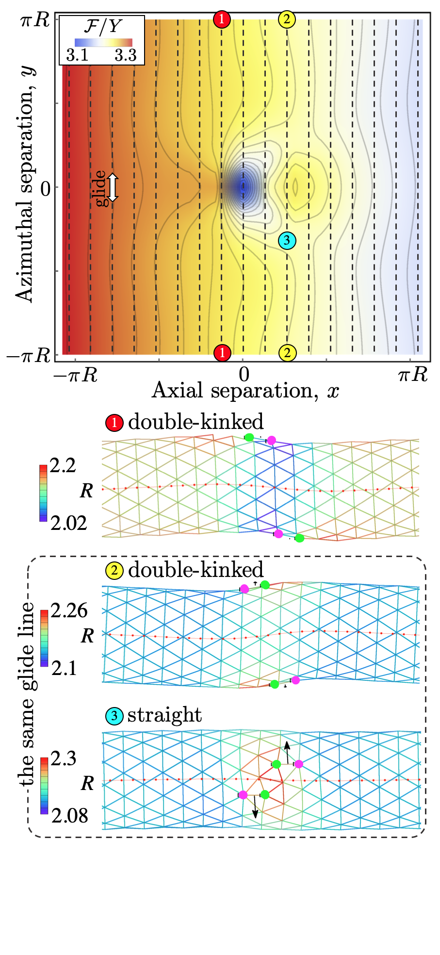
As a first test case for dislocation pair-interactions in the freestanding tubular crystal, we consider an tube with reduced bending rigidity and with a dislocation pair described by Burgers vector orientations . The chosen dislocations are restricted to glide circumferentially along closed paths at constant . In Fig. 2a, we plot the numerically calculated energy landscape as a function of axial and azimuthal separations and between the defects, with held fixed in any one realization while glide alters (dashed lines). It is immediately apparent from Fig. 2a that the stable -separations depend strongly on , in a manner that lacks the symmetry of Eq. 3. An energy gradient from positive to negative arises from the bending energy’s preference for dislocation motions that increase the tube radius BellerPRE16 ; however, this gradient has no effect in our chosen example because is fixed.
Instead, we draw attention to the locations of energy minima along the glide lines of constant . According to Eq. 3, the fixed-cylinder case has no metastable states; there are either two equal minima, symmetrically placed around , for , or one minimum at maximal azimuthal separation for (Fig. 9a in Appendix D). For the freestanding tube, we find a strikingly different energy landscape. At small , the absolutely stable state is at , a configuration that the tube accommodates by taking on a double-kinked shape with oppositely oriented kinks at each dislocation (states 1 and 2 in Fig. 2a). Another pair of local minima, with smaller symmetrically placed about , are metastable. In these configurations, disclinations of like sign are close to each other (state 3 in Fig. 2a), generating similar local surface deformations whose overlap is costly; meanwhile, the tube axis remains approximately straight.
Notably, the metastable states at small are not symmetric about . For , where the negative disclinations are nearer to each other (i.e. the positive disclinations are on the outside), the region between the dislocations has smaller radius and thus higher bending energy in the vicinity of the defects, which effectively makes the dislocations more attractive, whereas for the bending energy pushes the dislocations apart in order to enlarge the tube’s wider central region.
At larger (where is stable in the rigid-cylinder case), here the absolutely stable state switches from to the small- pair of states. A contributing factor in this swap is the decreased repulsion between dislocations, owing to their overlapping surface deformations, as their separation increases. Gradually, on further increasing , the -locations of the absolutely stable states move out toward , eventually approaching the prediction of Eq. 3. The special case of , for which dislocations could pair-annihilate at , unsurprisingly has a global minimum at ; but, more interestingly, there still exists a metastable state at with a kinked tube axis. Overall, our calculations show in this example that the freestanding tubular crystal has a richer landscape of effective defect interactions, with less symmetry and new metastable states, as compared with the crystal on a fixed cylinder.
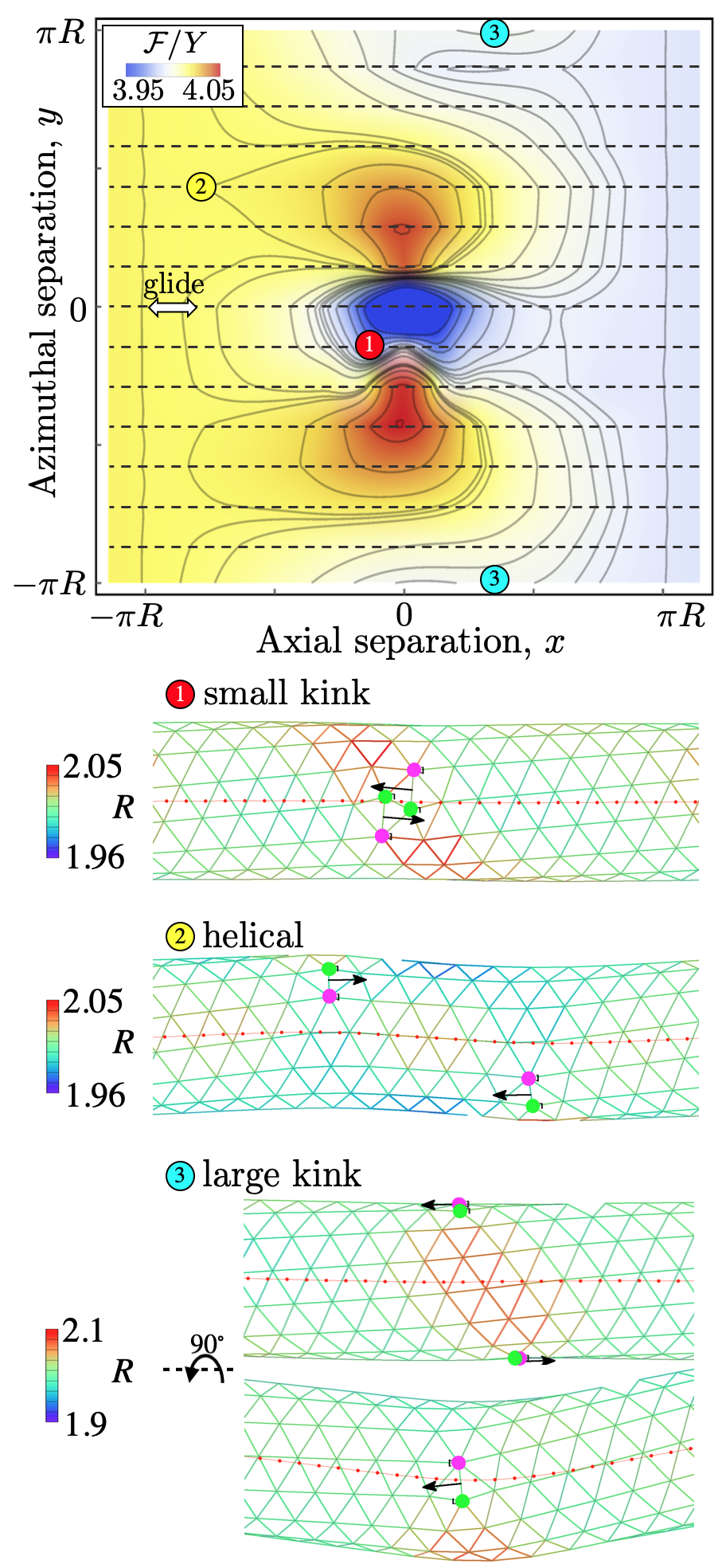
For another illustrative example of metastability in dislocation interactions, we next examine a dislocation pair gliding along the tube axis at , in an armchair lattice prescribed by . Each dislocation now has fixed and variable . The choice minimizes for a given according to Eq. 2, which diminishes the decrease in bending energy associated with tube-widening glide moves. Therefore, we expect that for small the stretching energy will dominate over the bending energy. In this regime, do defects in the freestanding tubular crystal act as they do on a fixed cylinder? For the latter, the analytical solution (3) predicts a pair of energy minima symmetric about for small fixed azimuthal separation , whereas for larger the dislocations repel indefinitely to large (Fig. S2b). At the defects attract each other and annihilate at . No metastable states are predicted at finite .
Figure 2b shows the energy landscape for the dislocation pair in a freestanding tubular crystal. When both dislocations move along the same glide parastichy (), they attract and annihilate, as in the fixed-cylinder case. However, whereas the energy landscape for the fixed cylinder has a single global maximum at , here we see a pair of maxima at situated near the minimum. This has a few consequences for stability when we fix in this landscape. The double minimum configuration exists only at , causing only small deflections from the initial shape (state 1 in Fig. 2b). Meanwhile, a new metastable state arises at intermediate azimuthal separations, as the inward-shifted energy maxima present a barrier to the bending energy’s push in the -direction (state 2 in Fig. 2b). The tube shape is helically deformed in these states, a generic consequence of kinks formed around defects at azimuthal separations neither nor . The energy barrier becomes smaller with increasing , until eventually the barrier disappears and the defects are able to glide freely to the tube ends, pushed by the bending energy to increase . However, when the defects are located on opposite sides of the tube at , there exists another metastable state (state 3 in Fig. 2b), which creates a shape with a single large kink in the tube axis ().
The kink angle caused by a single dislocation can be predicted based on Burgers vector orientation and tube radius . The lattice contracts by one lattice spacing in the radial direction at with no change in chirality, and it shrinks by in the longitudinal direction at . Since the longitudinal component of contraction, , mainly contributes to the tube axis reorientation, a single dislocation causes a kink angle , which agrees well with the simulation results.
Extending this calculation to pairs of dislocations, we first note that two defects with parallel Burgers vectors on opposite sides of the tube cancel each others’ effects on the tube axis orientation, whereas antiparallel doubles the net kink angle. Defects at general azimuthal separation reduce each others’ contributions to the kink angle by a factor , where is the angle between the Burgers vectors of the two dislocation defects in the cylindrical projection of the tube into a plane. Thus, our prediction for the total kink angle reads , which is in excellent agreement with the simulation results at , , , corresponding to state 3 depicted in Fig. 2b.
The two examples we have presented so far reveal metastable states under dislocation glide that are unique to the freestanding tubular crystal. These states produce (and are stabilized by) kink-bent, double-kinked, or helically kinked tube conformations in competition with straight or nearly straight conformations.
IV Control parameters for multistability
We now demonstrate that our principle of dislocation-mediated shape multistability is versatile, as it can be controlled by a number of parameters. Some of these parameters could conceivably be changed dynamically during an experiment, such as through external forces or a temperature dependence of material constants.
IV.1 Bending rigidity
| (a) | (b) |
|---|---|
 |
 |
| (c) | (d) |
|---|---|
 |
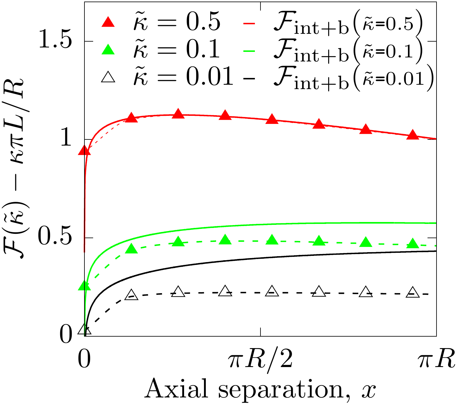 |
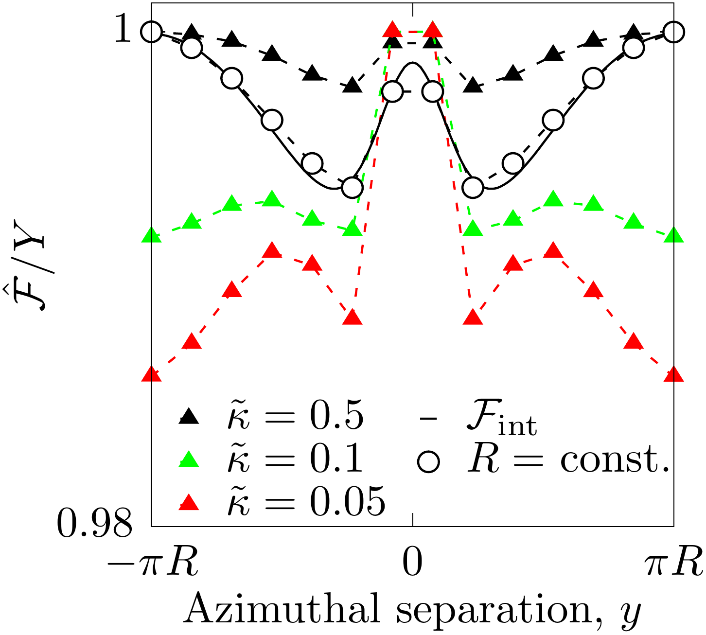
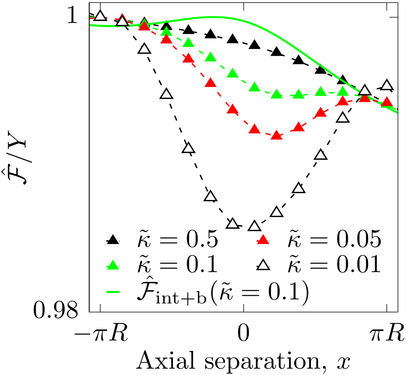
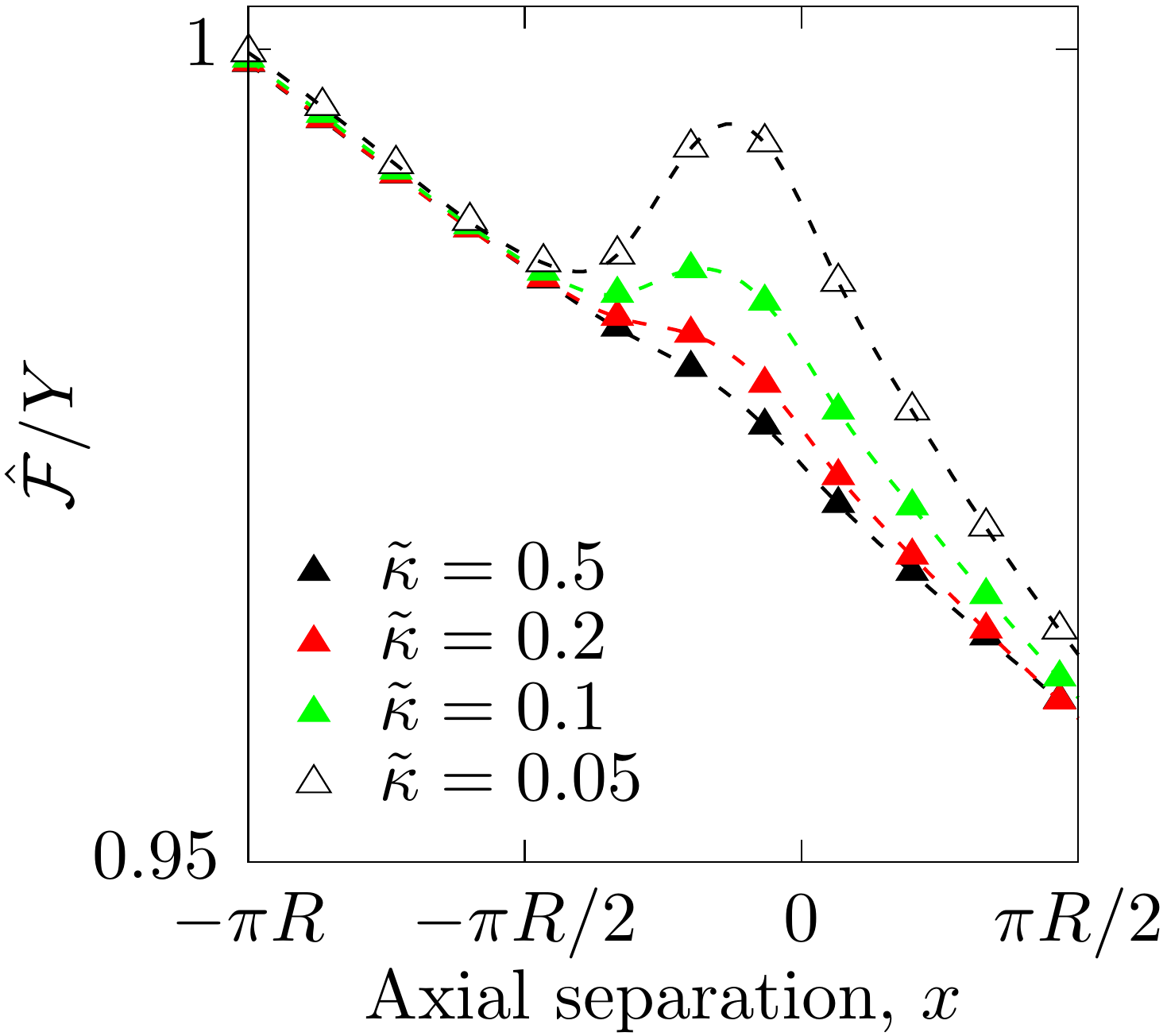
First we examine how the energy barrier and the difference in energy between stable configurations depend on reduced bending rigidity . Smaller favors metastable states in two ways: by permitting localized tube deformations to accommodate nearby dislocations, and by reducing the tube-widening stress that pushes defects to infinite separation. Thus, as we show below, changing in situ can cause a snap-through transition between two (meta)stable tube shapes or destabilize a formerly metastable state.
Returning to the tube, for two dislocations with azimuthally-oriented Burgers vectors () we test the multistability at noted above (states 2 and 3 in Fig. 2a) under changing . As shown in Fig. 3a, the configuration at separation , which is absolutely stable in a soft lattice at small (red triangles in Fig. 3a), becomes metastable at intermediate and then unstable when , in favor of the competing stable configuration at small . For comparison, we also show the corresponding calculation for the fixed-cylinder case: By constraining all particles to lie in a cylindrical surface, we obtain excellent agreement with the analytical prediction of Fig. 3 (open circles, black solid line in Fig. 3a). In this example, the fixed-cylinder crystal follows the trend observed with increasing in the freestanding case, as is highly unstable in favor of small .
A similarly significant -dependence can be seen in the highly bent shape observed in the tube for and fixed , which as noted above has a metastable configuration at small, positive (state 3 in Fig. 2b). We show in Fig. 3b that this state is very stable for small , then weakly metastable for intermediate , and finally unstable at large requiring the defects to glide apart indefinitely. The fixed-cylinder analytical prediction predicts a metastability near , not seen in our simulations of freestanding tubes, due to an energy barrier centered at . Interestingly, the predicted from Eq. 3 retains starkly different stable states from the computed results even when we add a naïve version of the bending energy per unit length, , using Eq. 2 for with changing abruptly at the -values of dislocations. The resulting total free energy prediction (green solid curve in Fig. 3b), is so different from the computed free energy at the same that the positions of maximum and local minimum are almost swapped.
So far we have examined only azimuthal and axial glide trajectories, but shape multistability arises also in the more generic case of glide along helical parastichies. As an example, we examine the case of in the tube, with constant climb separation . We find a local energy minimum at (Fig. 3c), in which the tube morphs into a helical shape, whereas a straight shape is recovered if the defects surmount an energy barrier at small to glide indefinitely toward . This energy barrier increases with decreasing , and similarly to the case, the metastable state can be attained only if the initial separation .
If we instead choose , allowing dislocation pair-creation or pair-annihilation, there is an energy barrier at small that divides a short-ranged attractive region, dominated by the stretching energy, from a long-ranged repulsive region, dominated by the tube-widening stress from the bending energy (red triangles in Fig. 3d). Indeed, our naïve bending energy term summed with the analytical stretching energy of Eq. 3 fits the data very well (red line in Fig. 3d). However, this agreement breaks down qualitatively at smaller , where the analytical approach predicts attraction at all due to the weakened repulsive influence of the bending energy (green, black solid lines in Fig. 3d). Instead, the computed results for the freestanding tube show that the dislocations become weakly repulsive for separations beyond just a few glide steps (green, black triangles in Fig. 3d). Evidently, the freedom to deform from the cylindrical reference state allows the freestanding tubular crystal to partially screen the interactions predicted by Eq. 3.
IV.2 External bending stress
(a)
(b)
(c)
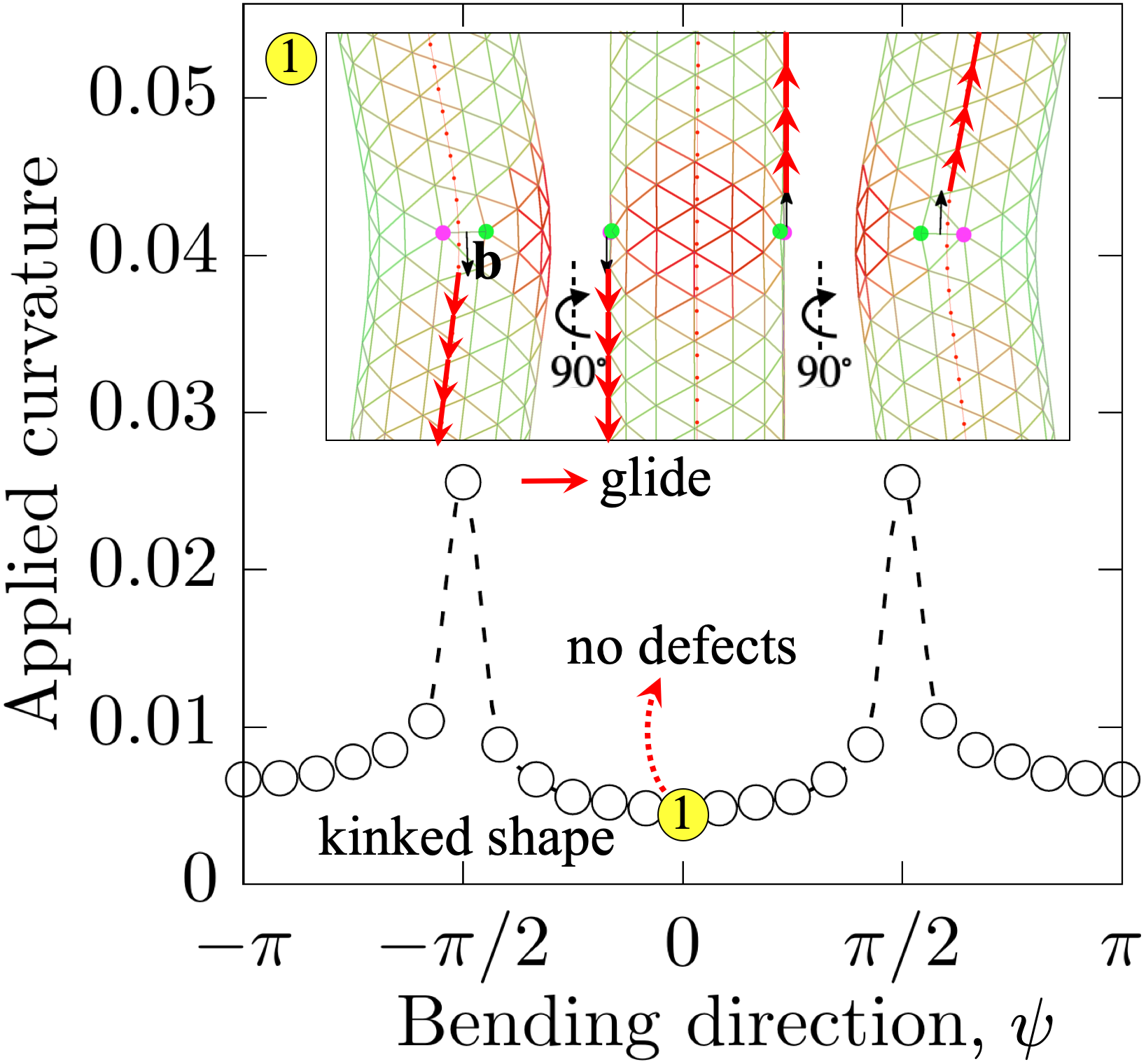
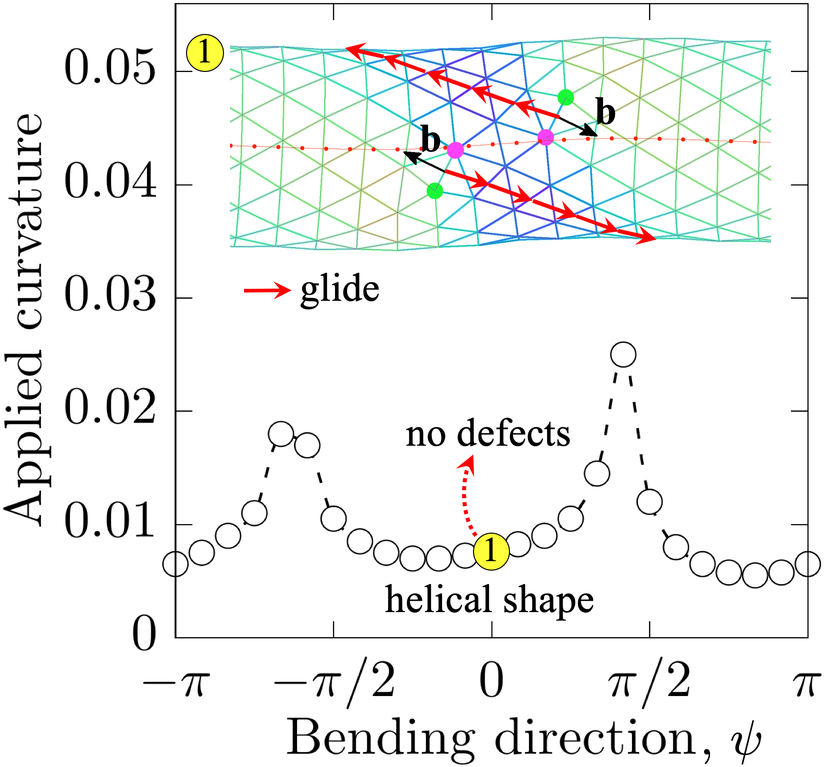
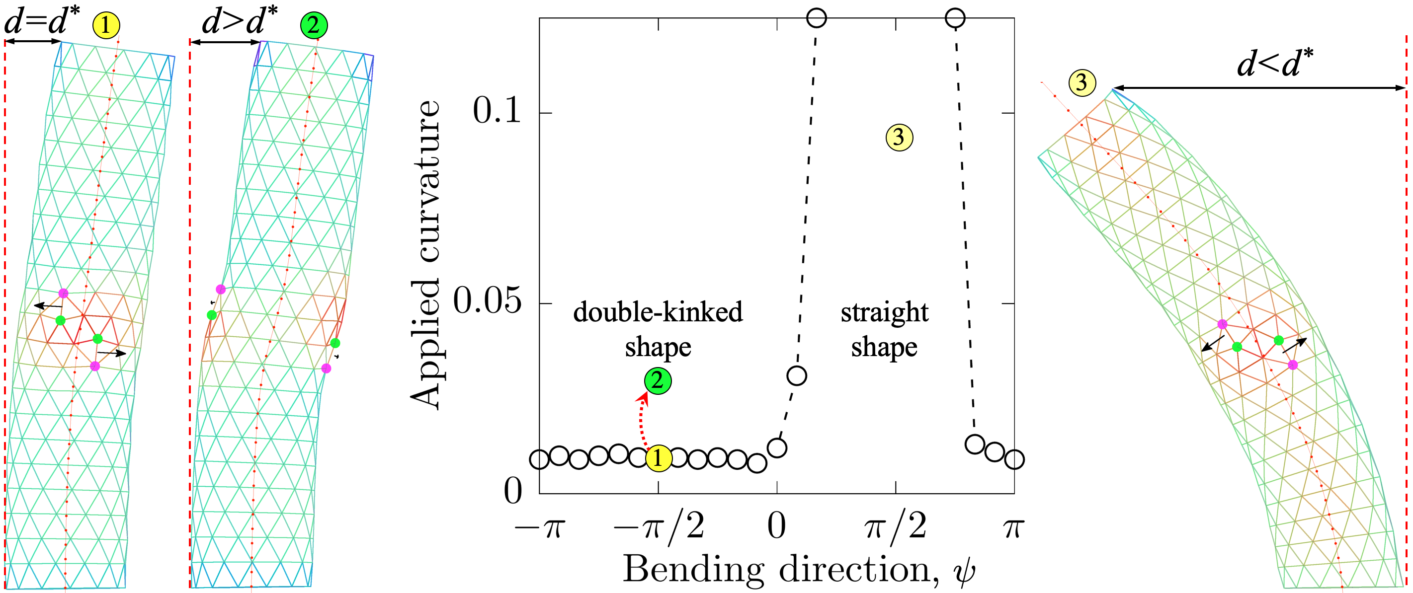
Externally imposed stresses present another set of routes to switching a freestanding tubular crystal between different (meta)stable states. Here we focus on external bending stress as a means of overcoming the energy barriers described above. The timescale for these switches is that of several glide steps, which we assume to be rapid enough to be observable lipowsky2005direct . We take as initial states some of the stable states identified above. To apply bending stress, the edge at one end of the tube is held fixed (taken to be clamped) while the other end is displaced from its reference position by distance , producing curvature along the tube of .
We first choose an angle in the plane to give, along with the initial tube axis , a plane of bending, such that compression is maximum along the direction picked out by . For convenience, we take to be the average initial azimuthal position of the two dislocations. Then we incrementally increase the imposed bending curvature from zero, checking the stability of both dislocations at each increment and performing glide steps whenever this lowers the total energy. For each bending direction , we thus find the critical curvature at displacement that destabilizes the initial defect configuration.
A particularly interesting case in which to study imposed bending is that of , and , as the dislocation pair can neither reach zero separation nor glide apart beyond a certain maximum distance. We found above that a pair of small- stable states, causing a nearly straight tube shape, are accompanied at smaller by a stable state at , which gives the tube a double-kinked shape (Fig. 3a). The straight and double-kinked shapes have approximately equal energy at . Using this value of , in Fig. 4a we examine a tube with two dislocations at a small climb separation , and an initially small azimuthal separation corresponding to one of the stable straight shapes (state 1). We find that the applied curvature necessary to enable the dislocations to glide apart, and produce the double-kinked shape (state 2), is highly dependent on bending direction ; for a large -interval, the straight shape remains stable even at large applied curvature (state 3). For other -values, bending easily produces a double-kinked shape which, by virtue of its energetic metastability, persists when the applied stress is removed. It is possible to reverse this transition, recovering the straight shape, by imposing bend in the other direction.
Interesting similarities and differences in this direction-dependent response to bending are seen when we examine the singly kinked shape at , , , , (state 1 in Fig. 4b), which already resembles a bent configuration even without external forces. In this case, for all values of , a finite applied curvature is found at which the state becomes unstable; the dislocations then glide apart to the ends of the tube, leaving behind no defects and thus a straight tube shape. However, the kinked shape is much more easily destabilized at or , when the dislocations are degrees away from the bending plane, than at , when the dislocations are in the bending plane. A similar transition to a defect-free state from a helical shape takes place in an tube with defects at and short separation (Fig. 4c). Since the shape is helical, this case lacks the symmetry seen in Fig. 4b. Taken together, the results in Fig. 4 suggest that the -dependence of changes smoothly with , such that the sharp peak at remains while the peak at diminishes and finally disappears as increases from zero to .
IV.3 Effect of spontaneous curvature
So far, we have assumed that the crystal has no spontaneous curvature, meaning that its ground state would be planar if it were “unzipped” from its cylindrical topology. But a spontaneous mean curvature clearly aids the assembly of a tube from a sheet, so it is important to address how such a material property will affect defect-mediated shape multistability. A plausible mechanism for such spontaneous curvature in microtubules is the presence of additional proteins that bind to adjacent protofilaments and change the angle at lattice contacts brouhard2014contribution . This provides anisotropic spontaneous curvature, with different preferred curvatures along principal directions. We similarly impose spontaneous curvature along one principal direction of the crystalline membrane, whereas the spontaneous curvature remains zero along the other direction, so that the bending energy is minimized in the initial, cylindrical state of a pristine tubular crystal. Details of the numerical implementation are described in Appendix A.
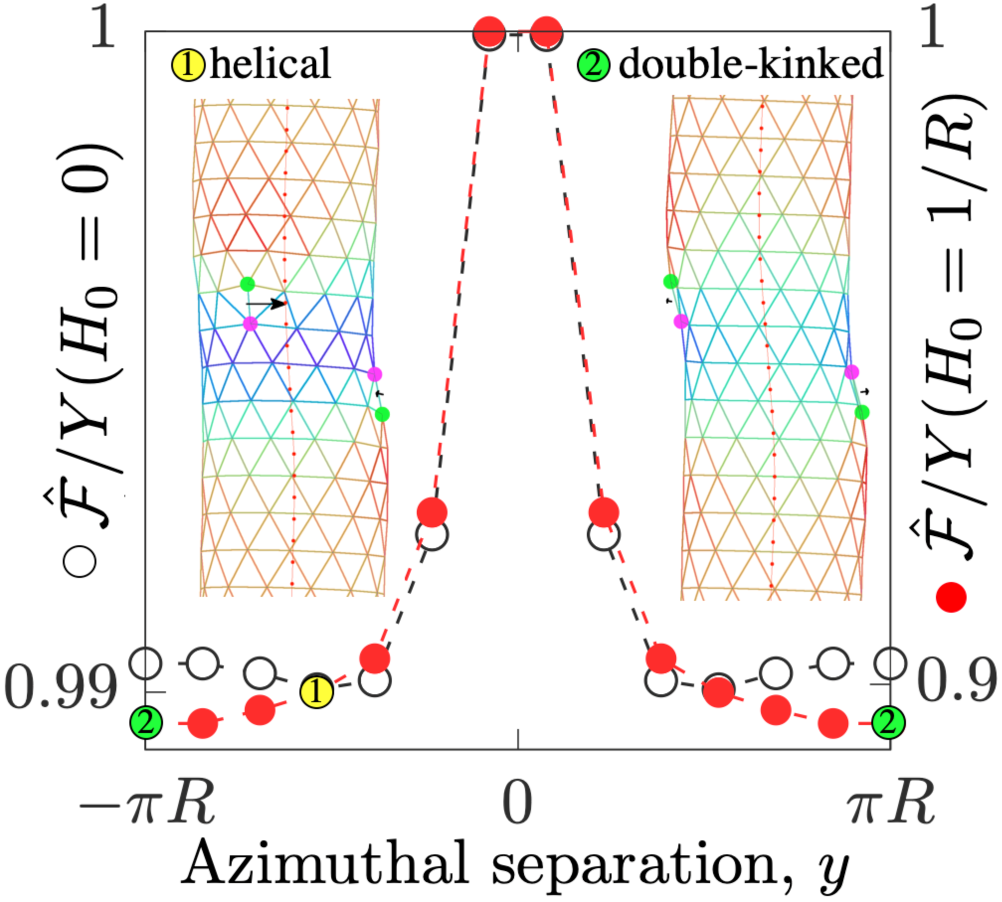
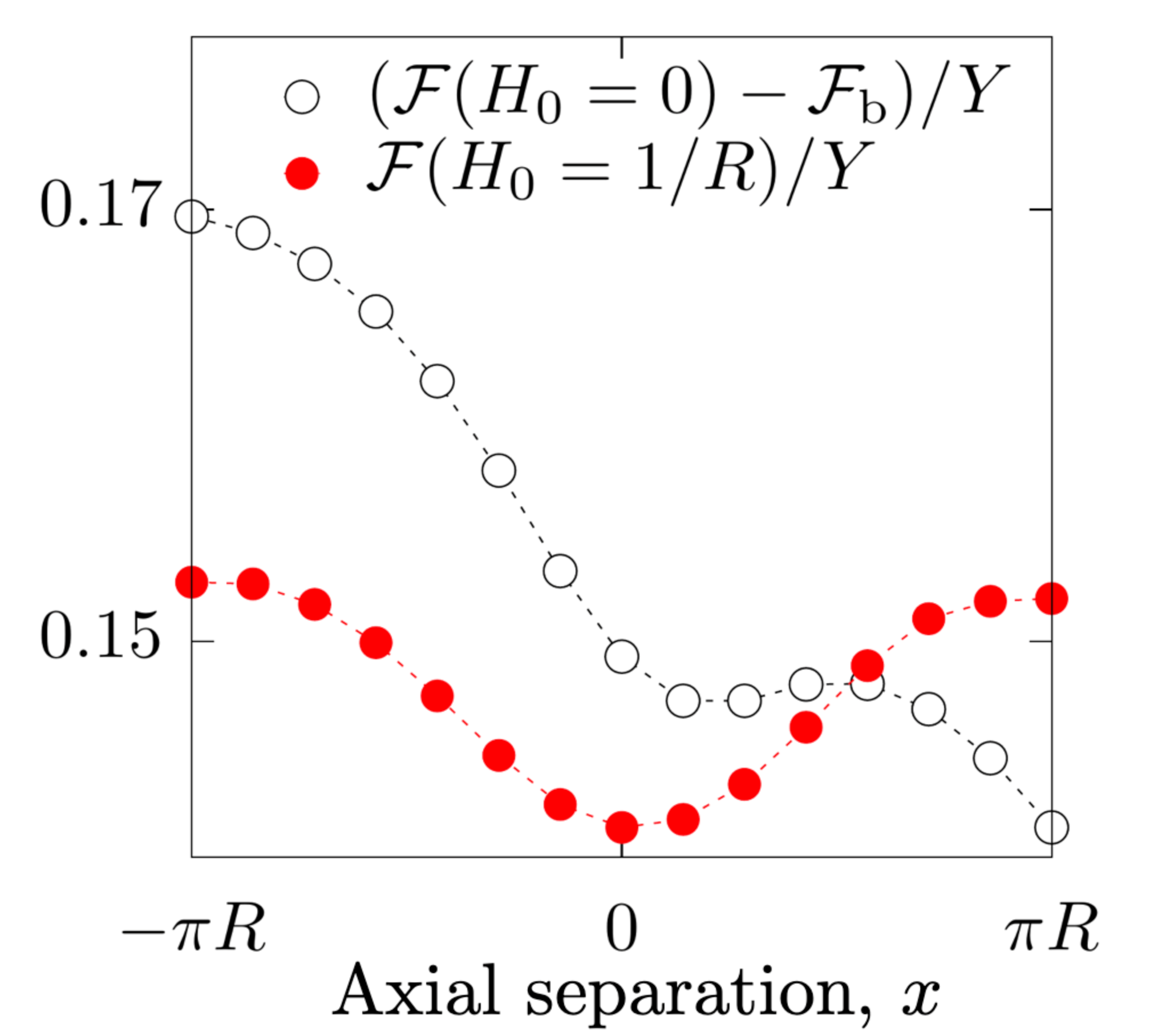
In Fig. 5 we illustrate with two examples that spontaneous curvature may change which tube shapes are stable and thus offers another potential control parameter. Without spontaneous curvature, two dislocations in an tube, oriented at and separated by , have two states (mirror reflections of each other) at short azimuthal separation (Fig. 2a) that lead to a helical shape (state 1 in Fig. 5a). Adding spontaneous curvature causes a transition to an absolutely stable double-kinked shape with defect separation . Another effect of spontaneous curvature is shown in Fig. 5b for a tube with defects gliding along the tube axis at , . The spontaneous curvature stabilizes the metastable state at small by increasing the energy barrier and reducing the bending energy loss due to glide (i.e. the slope of the energy’s dependence on is decreased). However, the global minimum-energy state is still the defect-free configuration occurring at , which can be reached, for example, by applied bending. Comparing Fig. 5 to Fig. 3a,b, we see that the introduction of spontaneous curvature has a similar effect to decreasing , with regard to which states defect separations are stabilized or destabilized. This can be rationalized by recognizing that the reference state is now a minimum of the bending energy, so the energy penalty for deviations from the reference state are of higher order in small bending distortions compared with the case of zero spontaneous curvature, which is always far from its locally preferred minimum.
We anticipate that spontaneous curvature also changes effective defect interactions in a manner similar to varying for other choices of Burgers vector orientation and phyllotactic indices . We leave for future work the computation of full energy landscapes at a range of values, examining here only two special configurations. Spontaneous curvature can also change locally and temporally in realistic scenarios, for example with temperature or with concentration of binding proteins alushin2010ndc80 ; wilson2008orientation , providing an additional way to control defect interactions and stable shapes.
| (a) | (b) |
|---|---|
 |
 |
V Designing target shapes via metastability and buckling
(a)
(b)
(c)
We now build hierarchically upon our findings for dislocation pairs to study interactions among multiple pairs of dislocations, as routes to targeting desired tube shapes over larger length scales. As we have shown, two dislocations with parallel gliding directions can be attracted to a number of possible stable configurations, depending on their climb separation and Burgers vector orientations, that significantly change the macroscopic shape of the tube. The main shape motifs we have found are kinked, double-kinked, helical, and (nearly) straight. We here take these shape elements as building blocks of programmable and switchable geometries at mechanical equilibrium.
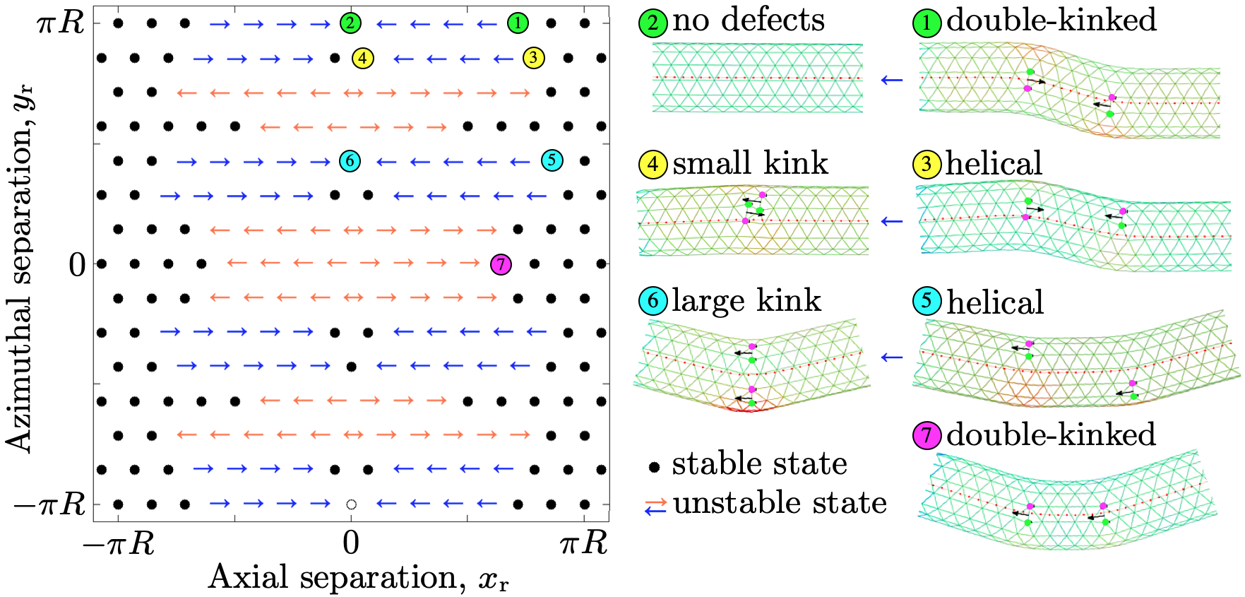
Because a generalization to interactions of arbitrarily many defects is impractical, we proceed by examining interactions of pairs of dislocation pairs, with each , dislocation pair in one of the stable states identified above for pair-interactions. The search space for stable configurations is then limited to just the relative , separation of dislocation pair 1 from dislocation pair 2. In Fig. 6 we show a variety of stable states for dislocation pairs in an tube with and constant separation , between the dislocations in each pair, each corresponding to state 3 in Fig. 2b. We initialize the two pairs of dislocation pairs at large separation and then gradually probe the energy landscape by alternate gliding of the two dislocations in one of the pairs while the other pair is held fixed. By this means we identify the critical separation at which the two dislocation pairs induce each others’ relative glide motion, while each pair maintains the stable separation between its two dislocations.
Our simulations show that the dislocation pairs remain stable at any azimuthal separation when their -separation is large, (black dots in Fig. 6a). Since each defect pair causes a kink in the tube axis, the azimuthal separation defines the resulting tube shape. At , for example, we obtain a double-kinked shape (state 1 in Fig. 6a) because the two pairs are oriented in opposite directions in the 3D embedding space, and thus the curvature at the two kinks has opposite sign. However, if , the dislocation pairs become attractive and annihilate (state 2), which is possible because at they glide along the same pair of parastichies. The final state is then a straight, pristine tubular crystal.
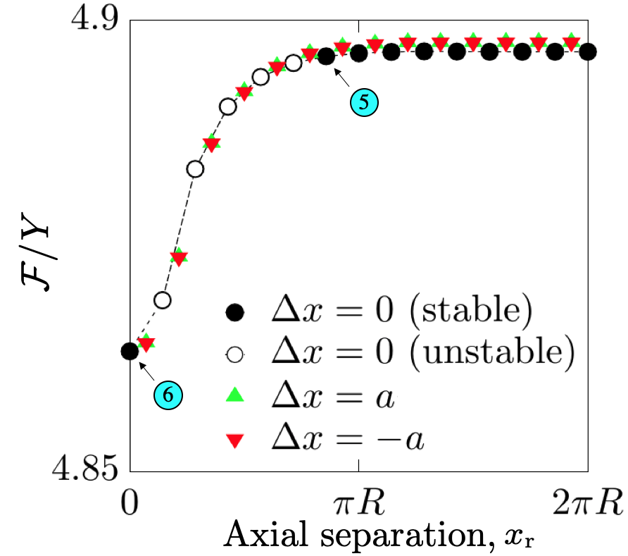
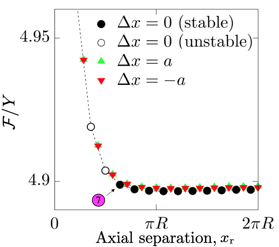
Dislocations also move along the same glide parastichies when , but now their Burgers vectors become parallel in the 3D space. As a result, pairs of dislocation pairs are repulsive at small and generate two identical kinks at larger separation (state 7). Intermediate azimuthal separations lead to stable helical shapes at large (states 3 and 5). Helicity arises due to bending of the tube in a different direction at each kink. At smaller , pairs repel for some -values but attract for others. Repulsion stabilizes the helical shape, whereas attraction stabilizes a small- shape with a single kink (states 4 and 6). The latter case presents a pathway for a spontaneous shape transition from a helical to a kinked conformation, if a small perturbation were to destabilize the helical state.
In Fig. 6b,c we show energy profiles with respect to axial separation at constant azimuthal separation . The stable states (filled black circles) correspond to the stable states in Fig. 6a, whereas unstable states (empty circles) are marked by arrows in Fig. 6a. For we see an alternation of locally stable and unstable states revealing a slight energy barrier encountered in gliding one dislocation away from its partner by , before the partner takes a glide step in the same direction. The energy landscape of the pair of dislocation pairs thus resembles the periodic Peierls potential felt by an individual dislocation, under the assumption that the time between glide steps is always long compared to the timescale for elastic relaxation. Besides this small oscillation, the energy remains essentially constant at larger .
However, for smaller initial separation , interactions between the two dislocation pairs overcome the energy barrier for glide steps, so that collective glide of the dislocation pair occurs spontaneously. For example, with a azimuthal separation between the two defect pairs, the two pairs approach until reaching the state with a single kink (state 6, Fig. 6b). On the other hand, when the two dislocation pairs repel at short distance until reaching a stable configuration at with two kinks of the same orientation (state 7, Fig. 6c).
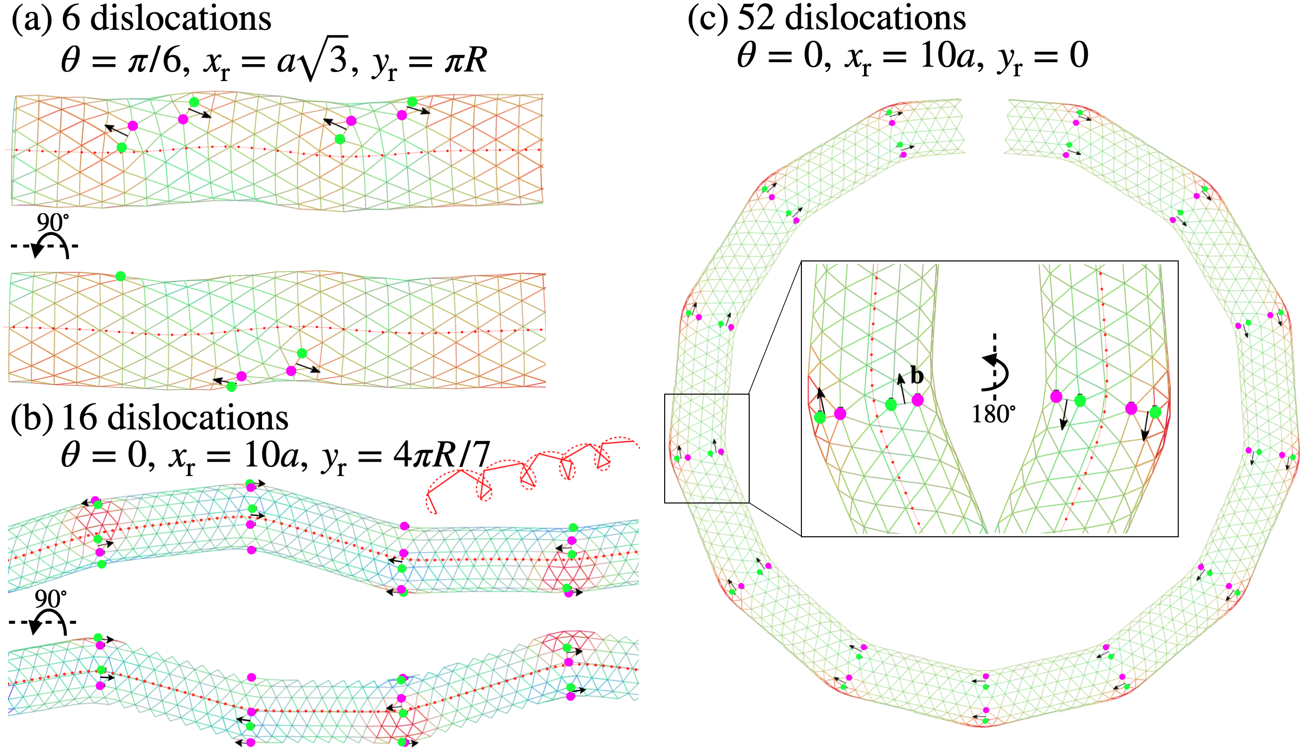
Having found stable configurations and corresponding tube shapes among pairs of dislocation pairs, we can now design more complicated geometries by adding dislocation-pair elements in a desired order. A series of stable dislocation pairs, arranged at constant separation between consecutive pairs, creates repeating kinks along the tube. Fig. 7a depicts an tube with three metastable pairs with Burgers vector orientation relative to the tube axis. The first and third pairs are located on one side of the tube whereas the middle pair is imposed on the opposite side (), and successive pairs have constant separation along the tube axis (). The combined effect of the three dislocation pairs leads to a tube shape that approximates a helical deformation.
Larger deformations can be generated by imposing dislocations with Burgers vectors parallel to the tube axis (). In Fig. 7b the tube has 16 dislocations that are localized in 4 equally separated groups along the tube (), each group consisting of two pairs and creating a large kink in the tube axis that corresponds to the absolutely stable state 6 in Fig. 6a. We impose dislocation groups at constant azimuthal separation (), which leads to rotations between successive kinks; as a result, the tube shape becomes approximately helical. The helical pitch and radius can be controlled by changing the rotation angle and separation between dislocation groups, and could even be varied along the length of the tube. The ratio between rotation angle and separation along the tube defines the torsion (), whereas the kink angle divided by separation approximates the curvature () of the helical shape. If there is no azimuthal separation between consecutive defect groups, , then the tube bends in the same plane at each group (Fig. 7c), and by imposing a series of metastable pairs we obtain tube shapes that approximate continuously curved planar geometries, such as a ring in the case of the torus-like structure of Fig. 7d.
VI Discussion
In this article, we have numerically demonstrated an emergent phenomenon of dislocation-mediated shape multistability in freestanding, flexible crystals of tubular geometry. Our simulations predict multiple metastable states restricting dislocation glide and causing macroscopic shape transitions, which make this system strikingly distinct from dislocations in a crystal attached to a rigid cylindrical substrate. We have explored this multistability by varying experimentally relevant design parameters for some chosen dislocation orientations and lattice helicity. Specifically, we found that changing the bending rigidity creates or eliminates certain metastable defect separations, and thus enables shape-morphing into nontrivial tube conformations, by altering the localization of surface deformations around the dislocations. Additionally, we showed that an external bending force allows dynamical control of dislocation motion between distinct stable configurations, enabling shape multistability even when material properties such as are fixed. We then demonstrated a new principle of shape programming by which imposed dislocation patterns generate shape-morphing into kinked shapes approximating targeted space curves.
The simulations presented in this work comprise just a few examples from a vast design space yet to be explored, opening multiple avenues for future investigations. Our approach can be generalized beyond dislocation groups with collinear Burgers vectors to collections of arbitrary dislocation orientations, generating new degrees of freedom and crossing glide paths. We have examined only a few sets of phyllotactic indices, focusing on achiral states for simplicity, and leaving for future work a systematic survey of values—and coexisting sequences thereof—which may enable new tube shapes. We conjecture that chiral lattices will respond to bend in a manner that interpolates between our observations in the armchair and zigzag achiral tessellations, but that the response to imposed twist will change rapidly as are varied zhang2009dislocation . Even more generally, dislocation-mediated shape multistability can be sought in other lattice types than the triangular lattice considered here, especially honeycomb and rhombic tessellations as closer analogues to carbon nanotubes and microtobules. Unbound disclinations, while outside the scope of this study because of their higher energy, are expected to further enrich the dislocation interaction landscape when they arise naturally on highly curved surfaces vitelli2006crystallography ; bowick2009two . Future exploration of these open questions will enable us to address the inverse problem: how to choose a prescribed defect pattern to obtain a desired, mechanically stable tube shape of arbitrary complexity.
Molecular dynamics (MD) simulations of freestanding tubular crystals will be important in extending our findings from the elastic networks explored here to objects with excluded volume, such as colloidal particles. Such a framework would also enable investigation of the role of assembly kinetics in forming dislocations, such as during colloidal assembly or, potentially, the assembly of tubulin dimers into protofilaments and microtubules. Some effects that we have ignored for simplicity, such as thermal fluctuations and the Peierls potential, can be more naturally incorporated in the MD framework. Also, while we have assumed isotropic elasticity in this work, breaking this symmetry in the monomer interactions will likely lead to new phenomena relevant to protein assemblies such as microtubules.
The distinctions that we have emphasized between the fixed cylindrical crystal and the freestanding tubular crystal highlight the need for new analytical approaches, incorporating the interplay of effective defect interactions and the curvature of the crystalline surface as it dynamically adapts to the defects’ presence. Our geometrical approach to calculating the tube axis kink angle is a step forward in this regard. However, computational approaches remain necessary for calculating mechanically stable tube shapes in the three-dimensional embedding space.
Inspired by the spherical crystal case, it is tempting to view the fixed-surface tubular crystal as a high-rigidity limit of the freestanding tubular crystal lidmar2003virus . As we have explored and exploited in this work, that assumption is not always correct: the tube axis in the freestanding case can change its orientation at the dislocation site, by whatever angle best relieves the stress induced by the dislocation, with no cost in extra strain at large distance. Therefore, the effective interactions between defects must incorporate the changes they induce in the crystalline membrane’s embedding in the 3D space.
The feedback that we observe between surface deformations and in-surface defect dynamics suggests connections to be explored between this work and other topics of current interest in soft matter physics, including: the stabilization of non-spherical droplet shapes in Pickering emulsions by packings of colloidal particles, often as crystals with many defects XiePickering ; motile disclinations in active matter on flexible, curved surfaces keber2014topology ; maroudas2020topologicalPublished ; and complex out-of-plane deformations in nematic elastomers with imprinted defects modes2011gaussian ; zakharov2015reshaping ; Gimenez_Pinto_2017 . We hope that our findings will spur experimental investigations of colloidal freestanding tubular crystals, mesoscale analogues to carbon nanotubes and microtubules, as a versatile platform for programmable, reconfigurable microwires with switchable mechanical and photonic response properties Kim2012Fabrication ; Solomon_2018 .
Acknowledgments
We thank Kinjal Dasbiswas and David R. Nelson for helpful comments. We gratefully acknowledge computing time on the Multi-Environment Computer for Exploration and Discovery (MERCED) cluster at UC Merced, which was funded by National Science Foundation Grant No. ACI-1429783.
References
- (1) A. Thess, R. Lee, P. Nikolaev, H. Dai, P. Petit, J. Robert, C. Xu, Y. H. Lee, S. G. Kim, A. G. Rinzler, et al., “Crystalline ropes of metallic carbon nanotubes,” Science, vol. 273, no. 5274, pp. 483–487, 1996.
- (2) A. Klug, “The tobacco mosaic virus particle: structure and assembly,” Philosophical Transactions of the Royal Society of London. Series B: Biological Sciences, vol. 354, no. 1383, pp. 531–535, 1999.
- (3) E. Nogales, “Structural insights into microtubule function,” Annual Review of Biophysics and Biomolecular Structure, vol. 30, no. 1, pp. 397–420, 2001.
- (4) M. Tymczenko, L. F. Marsal, T. Trifonov, I. Rodriguez, F. Ramiro-Manzano, J. Pallares, A. Rodriguez, R. Alcubilla, and F. Meseguer, “Colloidal crystal wires,” Advanced Materials, vol. 20, no. 12, pp. 2315–2318, 2008.
- (5) B. Yakobson, “Mechanical relaxation and “intramolecular plasticity” in carbon nanotubes,” Applied Physics Letters, vol. 72, no. 8, pp. 918–920, 1998.
- (6) I. Adler, D. Barabe, and R. V. Jean, “A history of the study of phyllotaxis,” Annals of Biology, vol. 80, no. 3, pp. 231–244, 1997.
- (7) M. F. Pennybacker, P. D. Shipman, and A. C. Newell, “Phyllotaxis: Some progress, but a story far from over,” Physica D, 2015.
- (8) F. Li, X. Badel, J. Linnros, and J. B. Wiley, “Fabrication of colloidal crystals with tubular-like packings,” Journal of the American Chemical Society, vol. 127, no. 10, pp. 3268–3269, 2005.
- (9) J.-F. Sadoc, N. Rivier, and J. Charvolin, “Phyllotaxis: a non-conventional crystalline solution to packing efficiency in situations with radial symmetry,” Acta Crystallographica Section A: Foundations of Crystallography, vol. 68, no. 4, pp. 470–483, 2012.
- (10) Y. Guo, B. G. P. van Ravensteijn, and W. K. Kegel, “Self-assembly of isotropic colloids into colloidal strings, bernal spiral-like, and tubular clusters,” Chem. Commun., vol. 56, pp. 6309–6312, 2020.
- (11) T. Li, B. Wang, J. Ning, W. Li, G. Guo, D. Han, B. Xue, J. Zou, G. Wu, Y. Yang, et al., “Self-assembled nanoparticle supertubes as robust platform for revealing long-term, multiscale lithiation evolution,” Matter, vol. 1, no. 4, pp. 976–987, 2019.
- (12) M. A. Lohr, A. M. Alsayed, B. G. Chen, Z. Zhang, R. D. Kamien, and A. G. Yodh, “Helical packings and phase transformations of soft spheres in cylinders,” Physical Review E, vol. 81, no. 4, p. 040401, 2010.
- (13) W. F. Harris and R. O. Erickson, “Tubular arrays of spheres: geometry, continuous and discontinuous contraction, and the role of moving dislocations,” Journal of Theoretical Biology, vol. 83, no. 2, pp. 215–246, 1980.
- (14) D. Chrétien, F. Metoz, F. Verde, E. Karsenti, and R. H. Wade, “Lattice defects in microtubules: protofilament numbers vary within individual microtubules,” Journal of Cell Biology, vol. 117, no. 5, pp. 1031–1040, 1992.
- (15) A. Mughal, H. K. Chan, and D. Weaire, “Phyllotactic description of hard sphere packing in cylindrical channels,” Physical Review Letters, vol. 106, no. 11, p. 115704, 2011.
- (16) D. Wood, C. Santangelo, and A. Dinsmore, “Self-assembly on a cylinder: A model system for understanding the constraint of commensurability,” Soft Matter, vol. 9, no. 42, pp. 10016–10024, 2013.
- (17) A. Mughal and D. Weaire, “Theory of cylindrical dense packings of disks,” Physical Review E, vol. 89, no. 4, p. 042307, 2014.
- (18) L. Fu, W. Steinhardt, H. Zhao, J. E. Socolar, and P. Charbonneau, “Hard sphere packings within cylinders,” Soft Matter, vol. 12, no. 9, pp. 2505–2514, 2016.
- (19) J. H. Moon, S. Kim, G.-R. Yi, Y.-H. Lee, and S.-M. Yang, “Fabrication of ordered macroporous cylinders by colloidal templating in microcapillaries,” Langmuir, vol. 20, no. 5, pp. 2033–2035, 2004.
- (20) C. Nisoli, N. M. Gabor, P. E. Lammert, J. Maynard, and V. H. Crespi, “Static and dynamical phyllotaxis in a magnetic cactus,” Physical Review Letters, vol. 102, no. 18, p. 186103, 2009.
- (21) C. Nisoli, N. M. Gabor, P. E. Lammert, J. Maynard, and V. H. Crespi, “Annealing a magnetic cactus into phyllotaxis,” Physical Review E, vol. 81, no. 4, p. 046107, 2010.
- (22) A. Amir, J. Paulose, and D. R. Nelson, “Theory of interacting dislocations on cylinders,” Phys. Rev. E, vol. 87, p. 042314, Apr 2013.
- (23) D. A. Beller and D. R. Nelson, “Plastic deformation of tubular crystals by dislocation glide,” Phys. Rev. E, vol. 94, p. 033004, Sep 2016.
- (24) B. I. Dunlap, “Constraints on small graphitic helices,” Physical Review B, vol. 50, no. 11, p. 8134, 1994.
- (25) M. J. Bowick and L. Giomi, “Two-dimensional matter: order, curvature and defects,” Advances in Physics, vol. 58, no. 5, pp. 449–563, 2009.
- (26) A. Bausch, M. J. Bowick, A. Cacciuto, A. Dinsmore, M. Hsu, D. Nelson, M. Nikolaides, A. Travesset, and D. Weitz, “Grain boundary scars and spherical crystallography,” Science, vol. 299, no. 5613, pp. 1716–1718, 2003.
- (27) J. Lidmar, L. Mirny, and D. R. Nelson, “Virus shapes and buckling transitions in spherical shells,” Physical Review E, vol. 68, no. 5, p. 051910, 2003.
- (28) V. Vitelli, J. B. Lucks, and D. R. Nelson, “Crystallography on curved surfaces,” Proceedings of the National Academy of Sciences, vol. 103, no. 33, pp. 12323–12328, 2006.
- (29) P. W. Ellis, D. J. Pearce, Y.-W. Chang, G. Goldsztein, L. Giomi, and A. Fernandez-Nieves, “Curvature-induced defect unbinding and dynamics in active nematic toroids,” Nature Physics, vol. 14, no. 1, pp. 85–90, 2018.
- (30) H. S. Seung and D. R. Nelson, “Defects in flexible membranes with crystalline order,” Physical Review A, vol. 38, no. 2, p. 1005, 1988.
- (31) T. Zhang, X. Li, and H. Gao, “Defects controlled wrinkling and topological design in graphene,” Journal of the Mechanics and Physics of Solids, vol. 67, pp. 2–13, 2014.
- (32) C. Modes, K. Bhattacharya, and M. Warner, “Gaussian curvature from flat elastica sheets,” Proceedings of the Royal Society A: Mathematical, Physical and Engineering Sciences, vol. 467, no. 2128, pp. 1121–1140, 2011.
- (33) A. Zakharov and L. Pismen, “Reshaping nemato-elastic sheets,” The European Physical Journal E, vol. 38, no. 7, pp. 1–6, 2015.
- (34) L. Giomi and M. J. Bowick, “Elastic theory of defects in toroidal crystals,” The European Physical Journal E, vol. 27, no. 3, pp. 275–296, 2008.
- (35) J. P. Hirth and J. Lothe, Theory of dislocations. Wiley, New York, 1982.
- (36) Y. Klein, E. Efrati, and E. Sharon, “Shaping of elastic sheets by prescription of non-Euclidean metrics,” Science, vol. 315, no. 5815, pp. 1116–1120, 2007.
- (37) A. S. Gladman, E. A. Matsumoto, R. G. Nuzzo, L. Mahadevan, and J. A. Lewis, “Biomimetic 4d printing,” Nature Materials, vol. 15, no. 4, pp. 413–418, 2016.
- (38) H. Aharoni, Y. Xia, X. Zhang, R. D. Kamien, and S. Yang, “Universal inverse design of surfaces with thin nematic elastomer sheets,” Proceedings of the National Academy of Sciences, vol. 115, no. 28, pp. 7206–7211, 2018.
- (39) C. P. Brangwynne, F. MacKintosh, and D. A. Weitz, “Force fluctuations and polymerization dynamics of intracellular microtubules,” Proceedings of the National Academy of Sciences, vol. 104, no. 41, pp. 16128–16133, 2007.
- (40) C. Janke and G. Montagnac, “Causes and consequences of microtubule acetylation,” Current Biology, vol. 27, no. 23, pp. R1287–R1292, 2017.
- (41) V. Hunyadi, D. Chrétien, H. Flyvbjerg, and I. M. Jánosi, “Why is the microtubule lattice helical?,” Biology of the Cell, vol. 99, no. 2, pp. 117–128, 2007.
- (42) T. A. Witten, “Stress focusing in elastic sheets,” Reviews of Modern Physics, vol. 79, no. 2, p. 643, 2007.
- (43) R. O. Erickson, “Tubular packing of spheres in biological fine structure,” Science, vol. 181, no. 4101, pp. 705–716, 1973.
- (44) L. D. Landau and E. M. Lifshits, Theory of Elasticity. Pergamon Press, New York, 1986.
- (45) L. Schaedel, S. Triclin, D. Chrétien, A. Abrieu, C. Aumeier, J. Gaillard, L. Blanchoin, M. Théry, and K. John, “Lattice defects induce microtubule self-renewal,” Nature Physics, vol. 15, no. 8, pp. 830–838, 2019.
- (46) A. Plummer and D. R. Nelson, “Buckling and metastability in membranes with dilation arrays,” Physical Review E, vol. 102, no. 3, p. 033002, 2020.
- (47) P. Lipowsky, M. J. Bowick, J. H. Meinke, D. R. Nelson, and A. R. Bausch, “Direct visualization of dislocation dynamics in grain-boundary scars,” Nature Materials, vol. 4, no. 5, pp. 407–411, 2005.
- (48) G. J. Brouhard and L. M. Rice, “The contribution of -tubulin curvature to microtubule dynamics,” Journal of Cell Biology, vol. 207, no. 3, pp. 323–334, 2014.
- (49) G. M. Alushin, V. H. Ramey, S. Pasqualato, D. A. Ball, N. Grigorieff, A. Musacchio, and E. Nogales, “The ndc80 kinetochore complex forms oligomeric arrays along microtubules,” Nature, vol. 467, no. 7317, pp. 805–810, 2010.
- (50) E. M. Wilson-Kubalek, I. M. Cheeseman, C. Yoshioka, A. Desai, and R. A. Milligan, “Orientation and structure of the ndc80 complex on the microtubule lattice,” The Journal of Cell Biology, vol. 182, no. 6, pp. 1055–1061, 2008.
- (51) D.-B. Zhang, R. D. James, and T. Dumitrică, “Dislocation onset and nearly axial glide in carbon nanotubes under torsion,” The Journal of Chemical Physics, vol. 130, no. 7, p. 071101, 2009.
- (52) Z. Xie, C. J. Burke, B. Mbanga, P. T. Spicer, and T. J. Atherton, “Geometry and kinetics determine the microstructure in arrested coalescence of pickering emulsion droplets,” Soft Matter, vol. 15, pp. 9587–9596, 2019.
- (53) F. C. Keber, E. Loiseau, T. Sanchez, S. J. DeCamp, L. Giomi, M. J. Bowick, M. C. Marchetti, Z. Dogic, and A. R. Bausch, “Topology and dynamics of active nematic vesicles,” Science, vol. 345, no. 6201, pp. 1135–1139, 2014.
- (54) Y. Maroudas-Sacks, L. Garion, L. Shani-Zerbib, A. Livshits, E. Braun, and K. Keren, “Topological defects in the nematic order of actin fibres as organization centres of hydra morphogenesis,” Nature Physics, pp. 1–9, 2020.
- (55) V. Gimenez-Pinto, F. Ye, B. Mbanga, J. V. Selinger, and R. L. B. Selinger, “Modeling out-of-plane actuation in thin-film nematic polymer networks: From chiral ribbons to auto-origami boxes via twist and topology,” Scientific Reports, vol. 7, mar 2017.
- (56) S.-H. Kim, H. Hwang, and S.-M. Yang, “Fabrication of robust optical fibers by controlling film drainage of colloids in capillaries,” Angewandte Chemie, vol. 124, pp. 3661–3665, mar 2012.
- (57) M. J. Solomon, “Tools and functions of reconfigurable colloidal assembly,” Langmuir, vol. 34, pp. 11205–11219, feb 2018.
- (58) J. Lüders and T. Stearns, “Microtubule-organizing centres: a re-evaluation,” Nature Reviews Molecular Cell Biology, vol. 8, no. 2, pp. 161–167, 2007.
- (59) V. I. Artyukhov, E. S. Penev, and B. I. Yakobson, “Why nanotubes grow chiral,” Nature Communications, vol. 5, no. 1, pp. 1–6, 2014.
- (60) A. Head, “X. the interaction of dislocations and boundaries,” The London, Edinburgh, and Dublin Philosophical Magazine and Journal of Science, vol. 44, no. 348, pp. 92–94, 1953.
- (61) L. Mitchell and A. Head, “The buckling of a dislocated plate,” Journal of the Mechanics and Physics of Solids, vol. 9, no. 2, pp. 131–139, 1961.
Appendix A Details of the discrete model
We consider a tubular crystal as a collection of hard spheres with positions forming a two-dimensional triangular lattice embedded in three spatial dimensions, with a preferred lattice spacing, . Neighbor-bonds, which would lie along lattice lines in a planar crystal, here lie along three families of helices. The geometry and chirality of a pristine (defect-free) tubular crystal can be conveniently defined using a pair of integer parastichy numbers , which give the number of distinct helices in the steepest right-handed and steepest left-handed families, respectively. Then the tube radius is defined by . The orientation of the lattice depends on the angle between the steepest left-handed helix and the cylinder axis as (Fig. 1) BellerPRE16 .
The discrete elastic energy of the tubular crystal is given by Eq. 1. The local curvature at each node is computed as , where the Gaussian curvature is expressed through the angles between two adjacent edges , and the mean curvature is defined over the adjacent edges, where are the two angles opposite to the edge in the two triangles sharing the edge . Here, is the observed area around a node , which is calculated as the average of the areas of the adjacent triangular faces. We choose the reference state to be a pristine triangular lattice with uniform spacing . In this state the elastic energy comprises only the bending energy, which depends on the cylinder radius and length as .
To account for nonzero spontaneous curvature, we slightly modify Eq. 1. We first calculate discrete mean and Gaussian curvatures, and from these calculate the discrete principal curvatures as . The local curvature energy density of Eq. 1 is then replaced by , always choosing .
We assume overdamped dynamics, and the positions of spheres change to minimize the elastic energy following the pseudo-time evolution equations . Here, is the friction coefficient associated with energy dissipation during relaxation of the elastic energy. For a given bond network, we allow the system to relax to an equilibrium configuration by minimizing the elastic energy over the node positions until the reduction in energy per update step becomes smaller than .
A single dislocation can be inserted by removing or adding a row of nodes to the lattice up to one end of the tube, such that the lattice remains pristine (6-coordinated) everywhere except at the dislocation, which consists of two nodes with 5 and 7 neighbors, respectively. Such a defect in a crystalline structure can be characterized by the Burgers vector connecting the gap in the Burgers circuit around the defect, , where is the displacement vector. A dislocation pair nucleation can be imposed by a single bond flip that removes a bond between neighboring nodes and replaces it with a new bond normal to it, thus creating two pairs of nodes with 5 and 7 neighbors. We validated our computational approach by reproducing the results of seung1988defects for critical bending rigidity at which a single dislocation causes a crystalline membrane to buckle. A dislocation glide move by one lattice spacing to a neighboring node is accomplished by a similar bond flip.
We assume a separation of time scales such that the elastic energy is completely relaxed to a state of mechanical equilibrium between consecutive glide moves. The direction of gliding is chosen to decrease the total elastic energy and can be along or opposite Burgers vector, or the defect can remain at the same position if it is a stable configuration depending on interaction with other defects, the tube shape, and external stresses.
This procedure gives rise to an effective energy landscape for the dislocations on the tubular crystal, whose local minima we explore in this work. For tubes with multiple dislocations, this landscape becomes high-dimensional and difficult to minimize rigorously as each test glide move requires a full minimization of elastic energy. Therefore, we examine stability by choosing a defect at random and performing a ”trial” dislocation glide in both directions, along and opposite to the Burgers vector; we then keep the configuration with the lowest total energy. If the given position of a defect is stable, i.e. any glide causes an increase in the total energy, then the dislocation is excluded from the next random selection until another defect is subject to glide and the bond network changes. This procedure continues while there are defects in the lattice and any possible dislocation glide step leads to a more preferable energy state. Otherwise, if all defects have been removed or are in a stable position, the configurations is considered to be at equilibrium. In our simulations we ignore the Peierls barrier during each glide step, assuming that thermal fluctuations enable the exploration of glide moves that we undertake quasi-deterministically. However, fully stochastic update rules or simultaneous glide might lead to other mechanically stable configurations that cannot be reached with our approach.
Appendix B Continuum approximation of a freestanding tubular crystal
The total elastic energy associated with deformations of a two-dimensional crystal approximated as a continuous elastic membrane can be written as a sum of stretching and bending contributions landau_elasticity given by
| (4) |
where are the Lamé coefficients associated with the two-dimensional Young’s modulus and Poisson ratio . The strain tensor is given in terms of the displacement field by and omits a quadratic term in because deformations are assumed to be small. The bending energy depends on bending modulus, , and local curvature that is written in the form of the Helfrich energy for membranes using the local mean curvature and Gaussian curvature . The relative importance of the bending and stretching contributions to the free energy, at the size scale of the tube radius , is given by the dimensionless Föppl-von Kármán number , which is usually very large because is typically small relative to lidmar2003virus .
The bending energy acts to increase the tube radius, creating a positive azimuthal strain and negative longitudinal strain , given at large by BellerPRE16 . The optimal radius of the pristine tubular crystal is then , where is the tube radius prescribed by minimizing the stretching energy alone. In the vicinity of a dislocation, deviations from a perfect cylindrical geometry are necessary to produce the expected surface buckling well known in planar 2D crystals seung1988defects .
Appendix C Single dislocation defect
In the main text we ignore boundary effects that will arise when the dislocation approaches the ends of the finite-length tubular crystal. Here we justify this simplification by showing that, for individual dislocations, the length scale for interactions between dislocations and the tube ends is very small, so that the ends have essentially no influence in the interior.
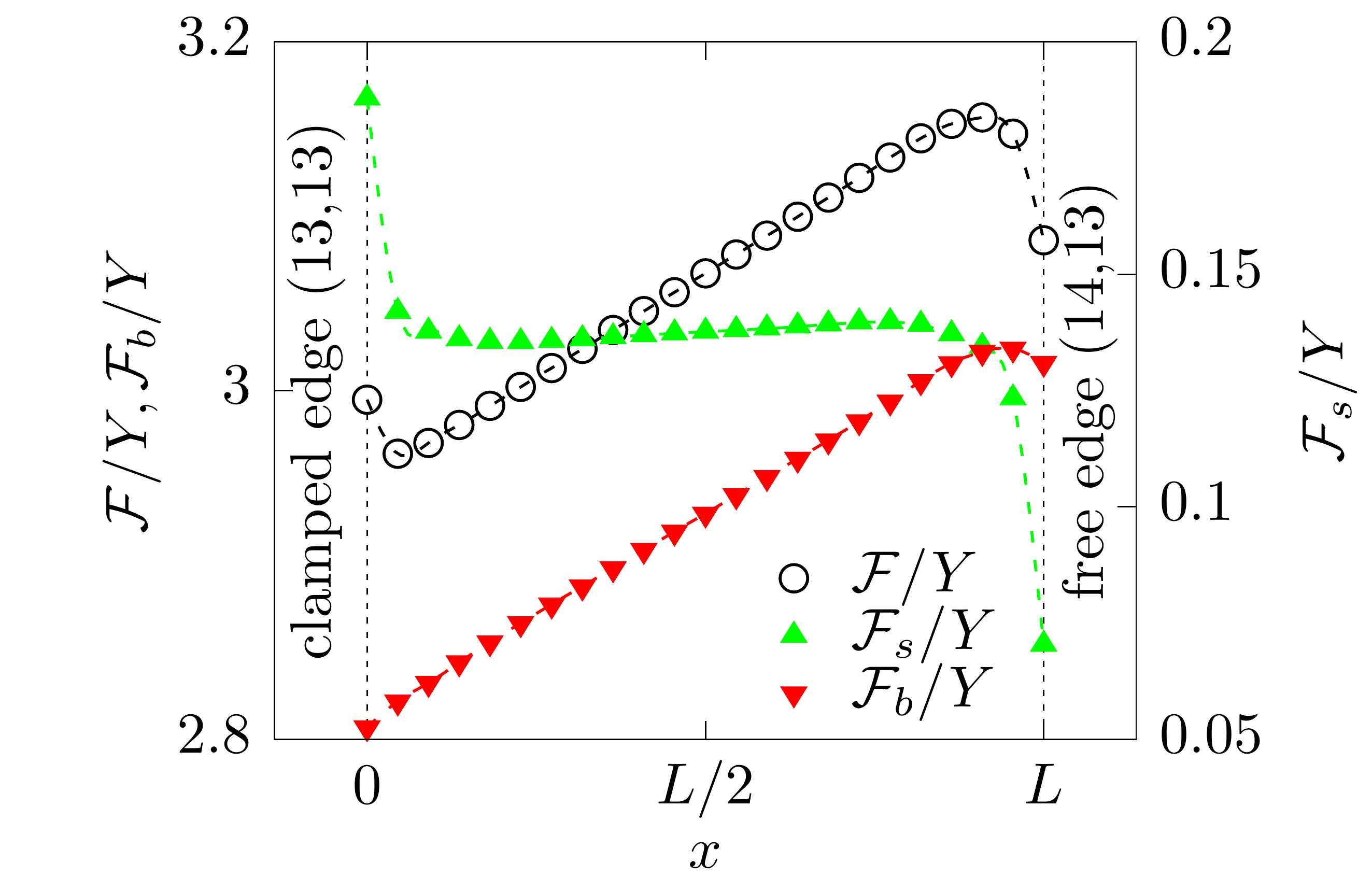
We construct an achiral lattice at , with one free edge and another firmly clamped edge that at which displacement of boundary nodes is disallowed. Then we impose a single dislocation with Burgers vector at angle to the tube axis. The dislocation causes a transition to in the tessellation in the part of the lattice closer to the free edge, slightly increasing the tube radius. If the tube is flexible and the dislocation is far from the tube edges, meaning that interaction with the boundaries is weak, the defect tends to glide toward the clamped edge, either along or opposite the Burgers vector, to increase the tube radius so that the bending energy is decreased. However, when the dislocation is imposed close to the free edge, at a distance less than three lattice spacings, it causes strong deformations of the tube, and the defect glides to the free edge to relieve the stretching energy, even though this bears a cost in bending energy (Fig. 8). On the other hand, if a dislocation is very close to the clamped end of the tube, the large cost in stretching energy acts to repel the defect to a stable state at a distance of two lattice spacing from the edge (the minimum of the total energy in Fig. 8). Such a configuration with one clamped and one free end resembles the microtubule (MT) structures with only one end firmly anchored to the organizing center where the MT starts to grow luders2007microtubule , or assembling single-walled carbon nanotubes with a rigid contact interface between the nanotube edge and the metal catalyst where the they nucleate artyukhov2014nanotubes . Also, we note that the numerical result for a flexible tube is similar to an interaction of a dislocation with a grain boundary in a 2D lattice Head53 , but only at small distance from the boundaries, where the forces exerted by the interface dominate and a dislocation is attracted to the free surface and repelled from an interface of larger shear modulus.
The energy savings due to the increasing tube radius when a dislocation glides along the tube defines the constant slope in bending energy with respect to glide distance for defects far from boundaries. Assuming that the transition zone, the region of a change in the parastichy numbers and tessellation, is narrow in the vicinity of a dislocation, the approximation for the slope is , where are the tube radii of different tubular tessellations. The stretching energy in Fig. 8 is an order of magnitude smaller than bending energy because a dislocation causes a local in-plane stress whereas the lattice has unavoidable bending energy at each node if there is no spontaneous curvature.
By this preliminary example we demonstrate that dislocations interact with the boundary via buckling and in-surface stresses. The direction of glide depends on the initial position and the distance from the boundary, and can be changed by the boundary conditions. This also allows us to estimate the deformation length around a defect at which the defect starts to interact significantly with the boundary. The deformation length caused by a dislocation in a tubular crystal is smaller than for a circular plate due to the cylindrical geometry constraint; for an isolated dislocation in a lattice of circular shape with free boundaries, the length was estimated to be of order at mitchell1961buckling ; seung1988defects . Thus, imposing defects farther than this deformation length from the boundaries allows us to avoid boundary effects.
Appendix D Interacting dislocations on a rigid cylindrical substrate
| (a) | (b) |
|---|---|
 |
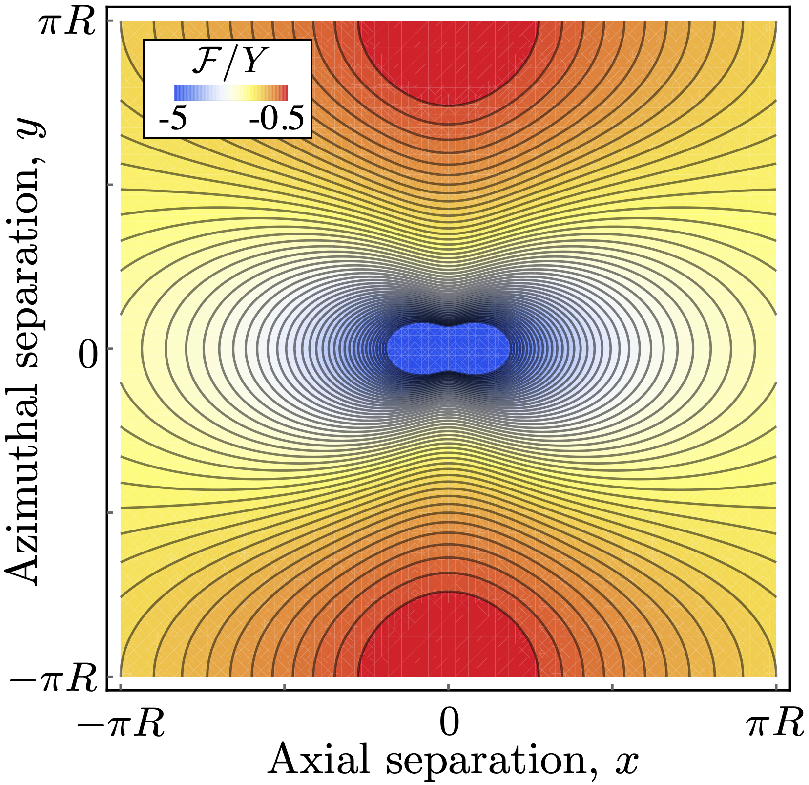 |
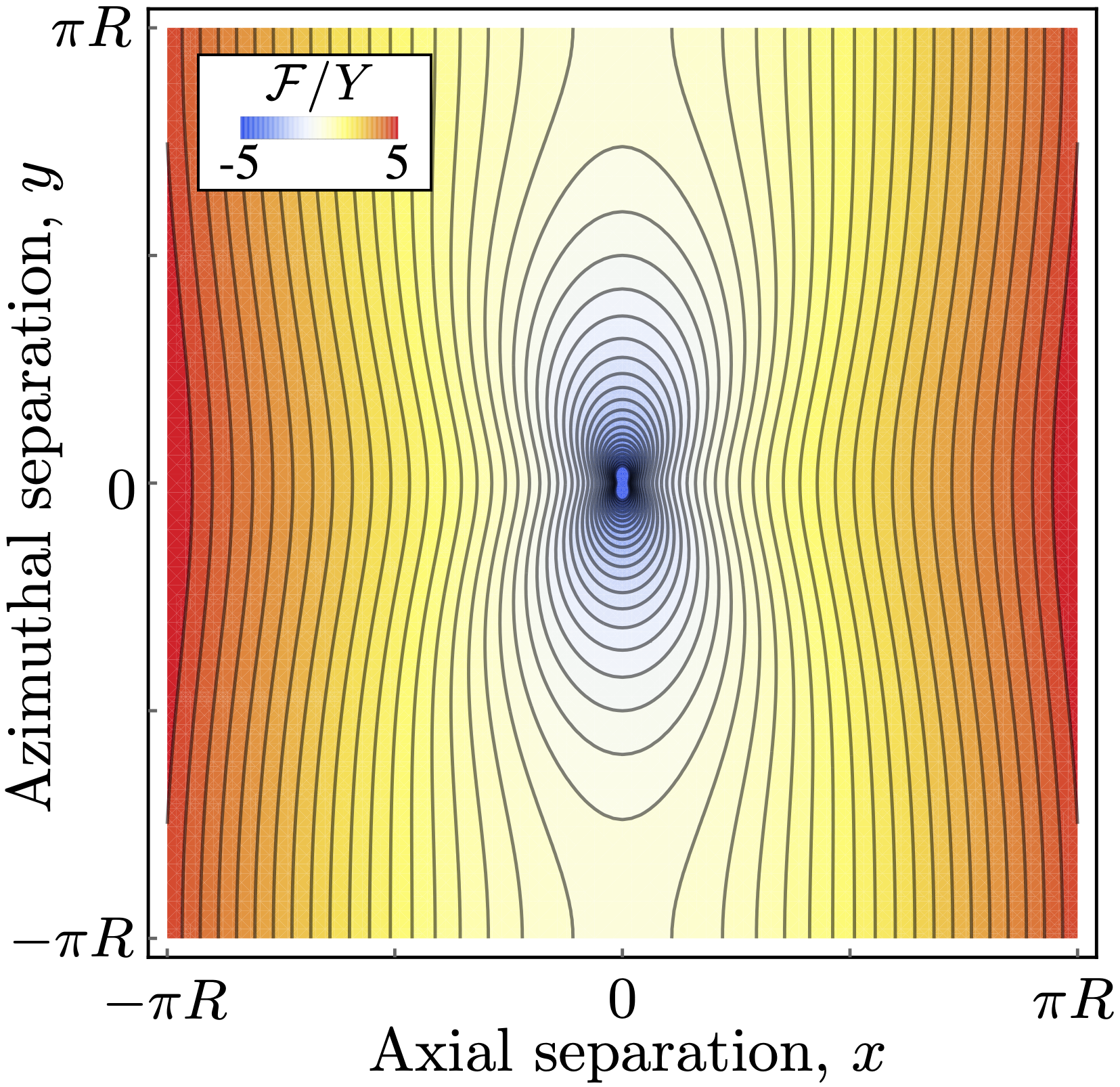
Here, for completeness, we provide stability diagrams for the dislocation pair energy on a cylinder calculated using Eq. 4 in the main text proposed in Amir13 ; BellerPRE16 . In Fig. 9 we plot the interaction energy corresponding to two separate dislocations with antiparallel Burgers vectors allowed to glide in the azimuthal () and longitudinal () directions. The energy landscapes are symmetric about the and axes, in contrast to our results for the freestanding tubular crystal, which is only symmetric under , due in part to the bending energy. At there is an unstable equilibrium (saddle point) at separation and two identical stable states at with the separation vector at to the axis. In the case of , a single maximum exists at separating two symmetric stable states with similar separation vector at to the axis. The absolute energy minimum is at the origin where the two dislocations annihilate, leaving behind a pristine lattice.
Appendix E Computation of the local tube radius
The local radius at a node is calculated as the shortest distance between the node and the centerline of the tube, . The centerline can, in general, significantly deviate from the axis in a pristine tube and have kinks along it due to dislocations. For tubes with a small deviation of the tube axis from the coordinate axis , we calculate the position of the centerline at discrete points lying in evenly separated parallel cross sections of the tube with the normal vector along . Position at each fixed is found as the equilibrium position where the and components of a fictitious repulsive force, exerted by all nodes in the lattice, vanish. The force from each node is oriented toward and has a power-law form, with amplitude decaying with the distance to a node as . The separation between cross sections is chosen to be small () allowing a dense discretization of the centerline. Then the local radius is computed as the distance to the nearest point on . In case of large deviations of the tube axis from , we calculate in cross sections constructed in a local frame rotated such that the local coincides with the tangent of calculated at previous step. This ensures small separation between points along .