Beam propagation simulation of phased laser arrays with atmospheric perturbations
Abstract
Directed energy phased array (DEPA) systems have been proposed for novel applications such as beaming optical power for electrical use on remote sensors, rovers, spacecraft and future moon bases, as well as planetary defense against asteroids and photonic propulsion up to relativistic speeds. All such scenarios involve transmission through atmosphere and beam perturbations due to turbulence which must be quantified. Numerical beam propagation and feedback control simulations were performed using an algorithm optimized for efficient calculation of real-time beam dynamics in a Kolmogorov atmosphere. Results were used to quantify the effectiveness of the system design with different degrees of atmospheric turbulence and zenith angles, and it was found that a large aperture DEPA system placed at a high altitude site is capable of producing a stable diffraction limited spot (Strehl > 0.8) on space-based targets for Fried length cm (@500nm) and zenith angles up to 60 degrees depending on atmospheric conditions. These results are promising for the next generation of power beaming and deep space exploration applications.
1 Introduction
Directed energy phased array (DEPA) systems are preferable to single aperture systems in directed energy applications that require large apertures for long range targets because of their scalability in both power and size. Scalability in power opens up a new mission space with high power requirements, and scalabilty in size allows illumination of targets at greater distances with minimal loss from diffraction. Existing monolithic single mode laser elements are limited to 10 kW in power [1] and meter-class aperture sizes at maximum. In principle, a DEPA could be built to have any power or diameter by incorporating the appropriate number of modular subelements. Furthermore, the ability to control the phase and alignment of each laser subelement provides a means to correct for atmospheric turbulence. These features make DEPAs a potential solution to various problems involving energy supply to distant objects on the ground, in the air or in space in scenarios where sunlight is insufficient or inaccessible. For example, sending power to the moon during the lunar night could be accomplished by using an Earth-based DEPA to provide optical power to a high efficiency tuned photovoltaic array on the moon. Power could also be sent to other extraterrestrial targets such as low Earth orbit, medium Earth orbit, geosynchronous and deep space spacecraft for power or propulsion. The latter could be done via photovoltaic conversion on the spacecraft to power high specific impulse ion engines and enable station keeping or rapid interplanetary transit. Kilometer scale arrays would be capable of diverting incoming asteroids off course by ablation, or accelerating low mass spacecraft to relativistic speeds for interstellar missions [2, 3]. Other applications include but are not limited to deep space communications, powering of ground-based remote sensors and rovers in inhospitable locations, remote sensing LIDAR, laser machining, and experiments involving matter under extreme conditions.
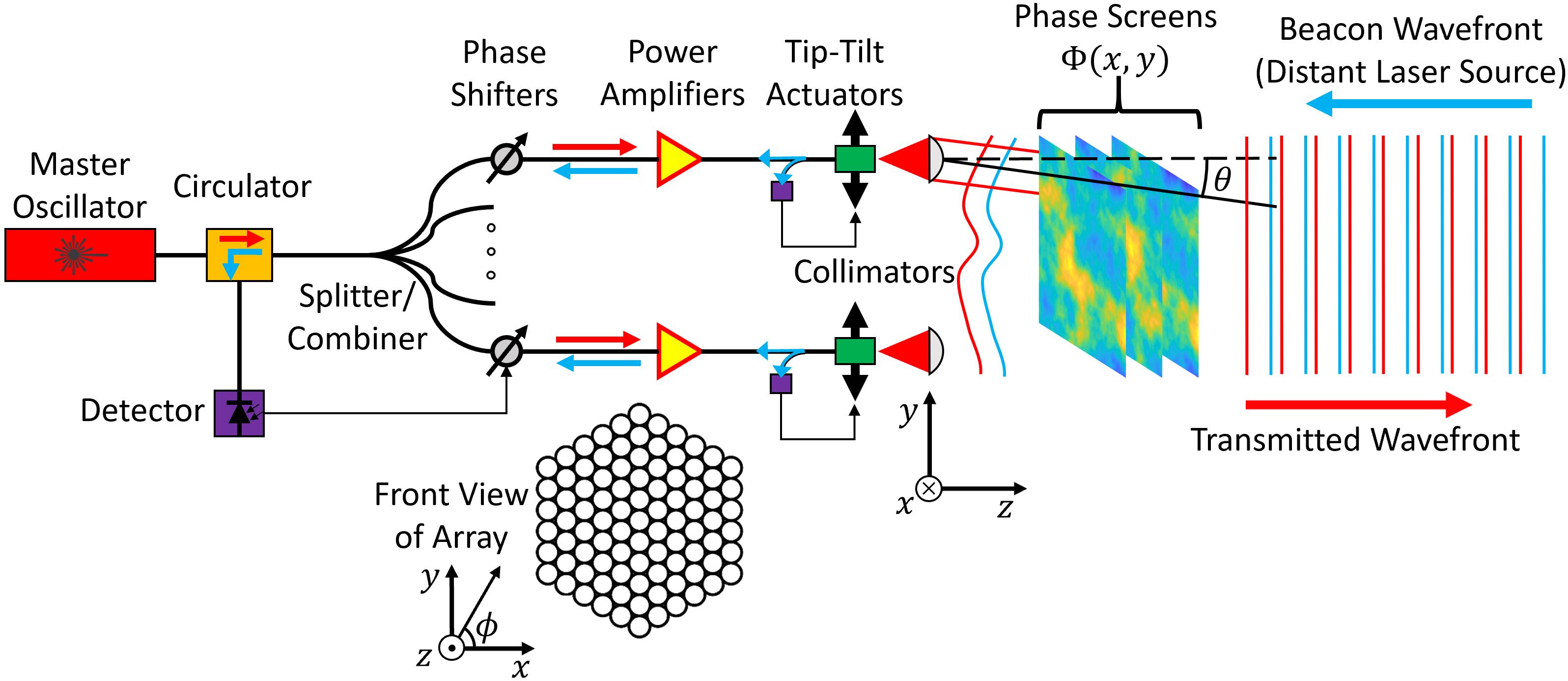
While it is feasible to construct DEPA systems for space-based applications in space to avoid atmospheric effects and increase target visibility, cost and accessibility make it far more practical to start with ground based systems. It is therefore of great importance to quantify the systems’ effectiveness in correcting for atmospheric perturbations. This study considers a ground-based continuous wave DEPA supplying power to a space-based target. This baseline DEPA is composed of a large number of circular sub-apertures of 10 cm diameter, which are hexagonally close packed so their edges touch each other. The target is equipped with a “beacon” laser, which illuminates the DEPA after being perturbed by the atmosphere. The atmosphere is modeled as a large number of two dimensional phase screens at different altitudes that represent the wavefront (phase) errors that a plane wave acquires as it travels in the zenith direction. The DEPA is equipped with sensors to measure the reverse-propagating beacon light and use it for phase retrieval and tip-tilt alignment. For simplicity we assume the target is stationary, making the results applicable to slow moving assets but not necessarily fast moving targets such as low Earth orbit satellites. Fig. 1 schematically represents the full system being simulated. The wavelength of both the beacon and transmit beams is assumed to be 1.064 m to take advantage of developed ytterbium fiber laser amplification technology and low atmospheric absorption [4, 3], though the model can easily be adapted to other wavelengths such as 1.55 m (erbium-doped fiber amplifiers) and 2 m (thulium-doped fiber amplifiers). This paper outlines how noise in such a system is modeled and provides simulated results for performance under various probable conditions at astronomical sites.
We utilize a recently developed DEPA beam simulation tool described in [5] to calculate the transmitted beam profile. Conventional propagation methods, such as the fast Fourier transform based angular spectrum method [6], are not well suited to handle large numbers of array elements with uniquely defined perturbations on each subelement. The computation time and memory requirements for parameterizing the near field DEPA beam to sufficient resolution are significant, and any FFT based algorithm is poorly scalable with array size unless many spatial measurement points of the beam profile at the target are needed. Our method works by summing the analytic electric field solutions of each subelement at a given measurement point. This operation makes parameterizing the near field beam trivial, and for subelements with a fixed number of measurement points it requires calculations. While this study deals with a modest number of subelements, the incorporation of temporal dynamics makes scalability of critical importance to enable swift calculation of the beam profile at many points in time. We use this infrastructure to simulate extremely large numbers of elements (, limited only by availability of computing resources) to calculate the beam profile at multiple points in time in parallel.
2 Simulation pipeline
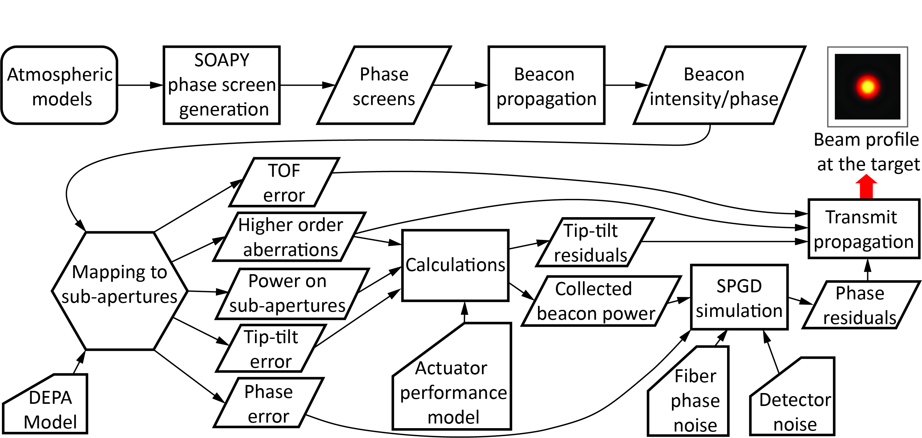
Fig. 2 summarizes the steps of a DEPA atmospheric simulation and how they connect to each other. First, atmospheric phase screens are generated with the Python extension SOAPY [7] using a modified Hufnagel-Valley (HV) model for atmospheric turbulence, and a modified Bufton model for wind speed (see Supplement 1, Section 2). The modifications of both models are informed by site survey data taken for the Thirty Meter Telescope (TMT) [8]. The phase screens are used to optically propagate the beacon to the DEPA and produce its intensity and phase as a function of space and time. The data is then mapped to the locations of the DEPA sub-apertures to produce time series for piston phase, tip-tilt error, incident beacon power, intensity reduction due to higher order aberrations, and time-of-flight error for each subelement. A model for tip-tilt servo performance is used to generate tip-tilt residual error, which is combined with incident beacon power and higher order aberrations to calculate the beacon power collected by each subelement. Beacon power and piston phase values, along with detector noise and data-based fiber amplifier phase noise, are used as inputs for simulation of the stochastic parallel gradient descent (SPGD) [9] phasing servomechanism. SPGD is an algorithm routinely used in adaptive optics systems to phase lock numerous subelements. The SPGD simulation generates residual piston phase errors for the transmit beam. The phase residuals, tip-tilt residuals, intensity reduction due to higher order aberrations, and time-of-flight effects are used as inputs for the transmit beam propagator to produce final results for the beam at the target. Each step of the process is described in further detail in Supplement 1, with exception of the optical propagation steps in the following section.
3 Optical propagation of beacon and transmit beam
The beacon is modeled as a plane wave propagating from the highest altitude phase screen to the ground. The electric field is iteratively calculated at the location of each phase screen to account for scintillation effects. Scintillation arises as an effect of the atmosphere refracting or scattering light in different directions, and the light interfering with itself as it propagates. The scintillation index represents the normalized intensity variance with respect to time at a given point in space, and is defined as [10]:
| (1) |
The plane wave model of the beacon makes initial parameterization of its electric field trivial, and we require a large number of spatial measurement points to accurately map it to the DEPA sub-apertures. These features make the angular spectrum method an appropriate propagator for [6]:
| (2) |
where
| (3) | |||||
| (4) |
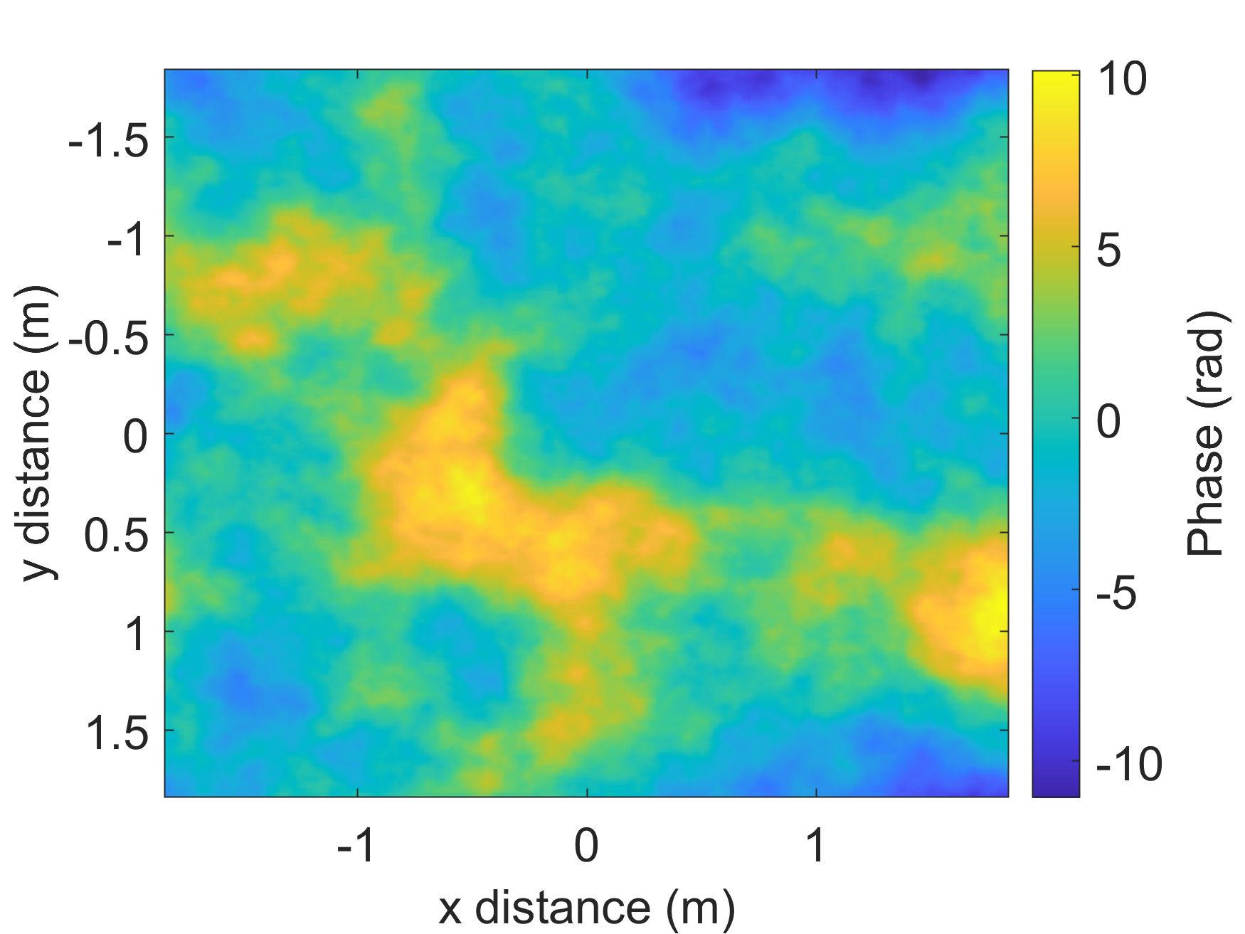
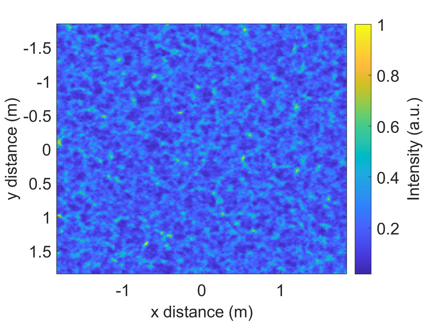
Here , , and are the spatial coordinates in Fig. 1, is the Fourier transform (or angular spectrum) of , and is the wave vector of the propagating light. is propagated in the direction by the term in Eq. (2), and inverse Fourier transformed to solve for . The paraxial approximation is employed in Eq. (4). Both and are efficiently calculated with fast Fourier transforms. Fig. 3 is an example of the phase and intensity of a beacon of 1.064 m wavelength at a given point in time after it propagates to the DEPA through an atmosphere with Fried length = 10 cm (for 500 nm wavelength) defined by the turbulence model discussed in Supplement 1. All values of in this paper unless otherwise specified are at a wavelength of 500 nm. , in agreement with theoretical and experimental results [11, 8].
The transmit beam of the DEPA is propagated using the method described in [5], which models each laser subelement as a Gaussian beam truncated by a circular aperture. The electric fields of subelements are found with their respective analytic solutions and added together to construct the synthesized electric field :
| (5) |
This method enables rapid parameterization of large DEPAs (above subelements demonstrated in [5]) with perturbations in phase, amplitude, position, output angle, and focal distance. Customized parallel computing allows for their electric fields to be quickly calculated on a GPU to great accuracy. In this study, we used a GeForce GTX 1070 and Titan-Z desktop GPU with double point precision.
The atmosphere is approximated to be “thin” when calculating the transmit beam profile, i.e. the beam encounters all atmospheric turbulence in the near field before propagating into the far field or focal plane. This simplification is valid for the discussed simulations since the total propagation distance is much larger than the thickness of the atmosphere [12, 13]. Another notable simplification is that the propagator does not model subelement aberrations of higher order than focal shifts. Losses in the main beam at the target due to these aberrations are still accounted for by reduction of the on-axis intensity of the subelements by the appropriate amount (see Supplement 1). Since all transmit beam calculations are done in the far field of the array, any differing effects will be contained in side lobes far outside our region of interest.
4 Numerical results for transmit beam
Simulations were performed for an array composed of circular sub-apertures packed hexagonally with touching edges to form a disk. The sub-apertures were 10 cm in diameter, making the full array about 3.4 m in diameter. The transmit and beacon wavelengths were both 1.064 m. While this is a specific configuration, the modularity of the subelements and known scaling relationships make the results applicable to a DEPA of any size (with the exception of piston phase errors) and targets at any distance. The measurement plane was set to be m away from the array (approximately the distance to the moon) and was 500x500 m with 5 m resolution, which provides about 1% error in estimating combining efficiency. Combining efficiency is defined as the ratio of optical power within an on-axis diffraction limited spot to the total power emitted by the array, and is a measure of the fractional power on the target. The spot diameter in angular units for a circular array of diameter and wavelength is , the first minimum of the Airy disk. For an array composed of circular sub-apertures which collimate Gaussian beams, the maximum achievable combining efficiency is 0.62 [5, 15]. This limit is due to a combination of diffraction effects and power clipping at the apertures.
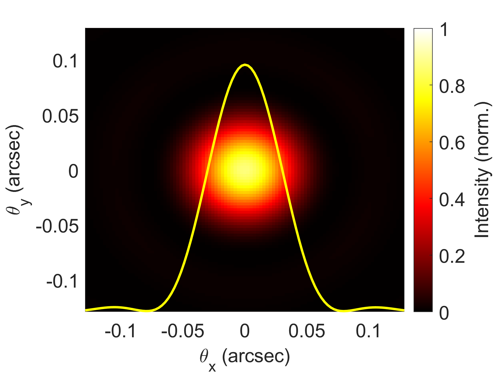
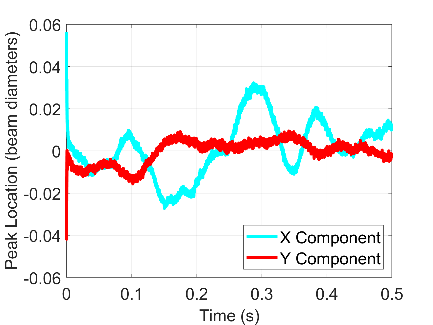
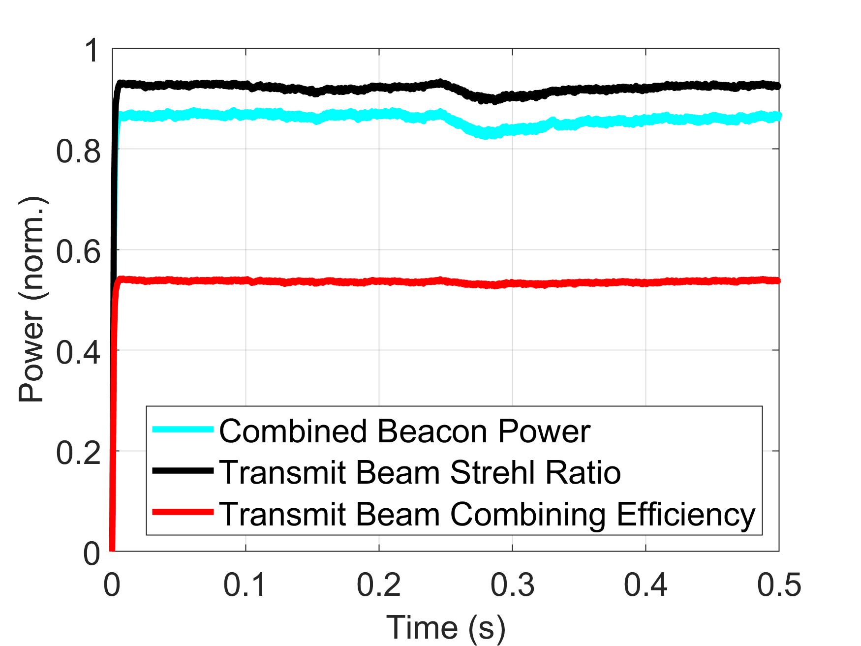
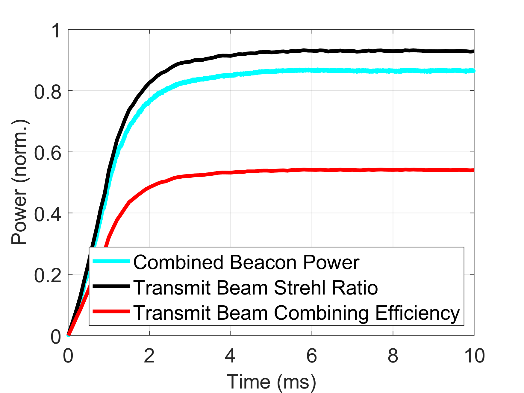
Fig. 4 shows measured beacon power, the Strehl ratio of the transmit beam, and combining efficiency of the transmit beam for Fried length = 15 cm (at 500 nm wavelength), ground wind speed = 5 m/s and zenith angle = 0 deg as a function of time. One can see that they are in close agreement with each other, taking into account their differing normalization factors. Here the Strehl ratio is defined as the ratio of peak on-axis intensity to that with no perturbations and does not take atmospheric transmission into account. Measured beacon power, on the other hand, is normalized to the power in a system with perfect alignment and no atmosphere. The average steady state Strehl is above 0.8, which is considered to be diffraction limited by the Maréchal criterion [14]. Fig. 5 displays the time-averaged spatial profile and peak location as a function of time for the same beam. Spatial coordinates are in angular units to make them independent of propagation distance. The beam diameter is inversely proportional to array diameter, as the main lobe of a properly phased DEPA has the same geometric properties as a single aperture of the same size and shape [5]. In this case the beam diameter is approximately 0.16 arcseconds (or 308 m for our propagation distance of m). The peak location was found by performing a Gaussian fit around the maximum intensity value. The fitting procedure increases the resolution of the location values, which allows for subtle motion to be seen in the beam. See Visualization 1 for a video of the beam’s spatial mode in these conditions, and Visualization 2 for a video in the harshest conditions simulated.
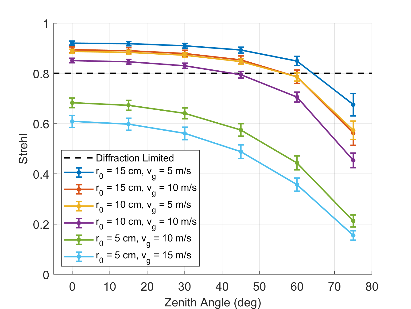
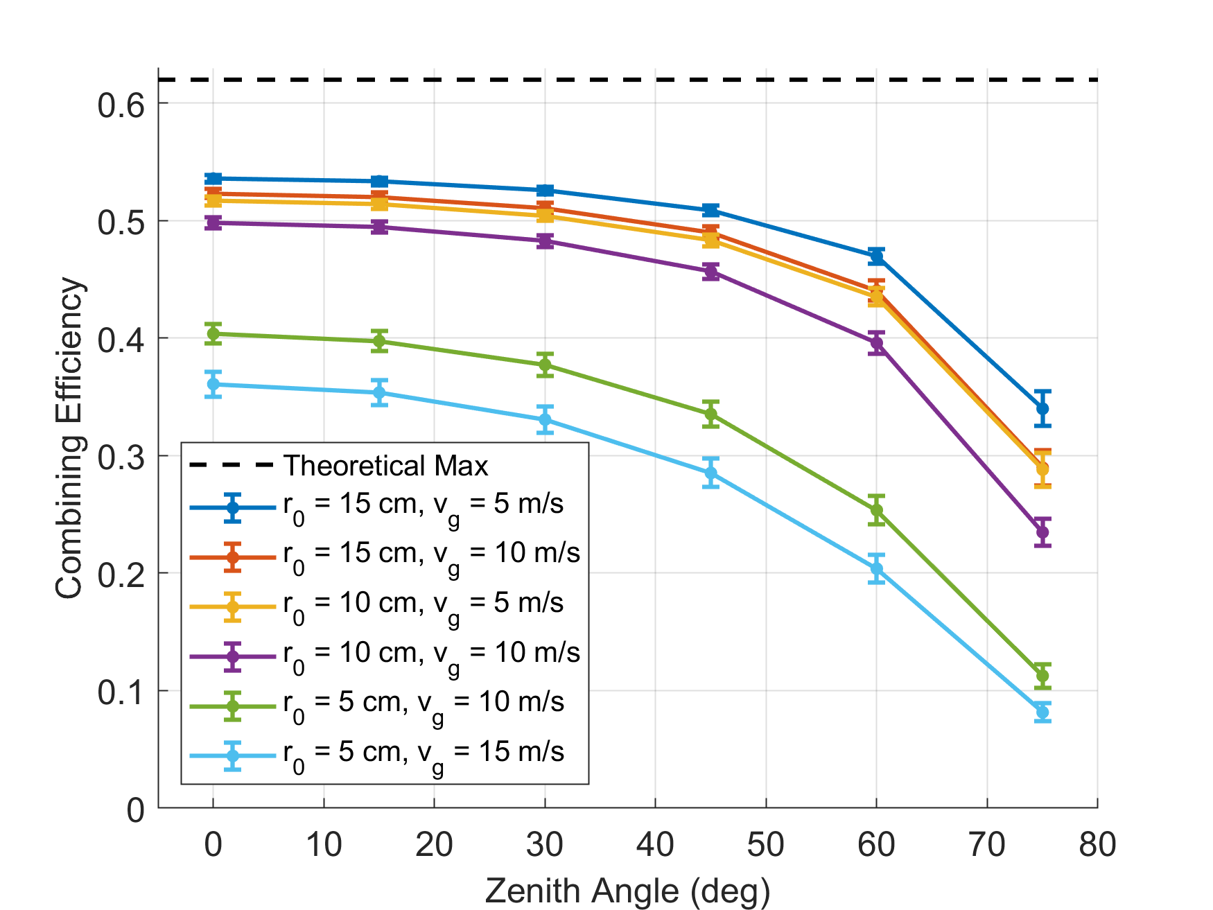
Figs. 6 and 7 summarize Strehl and combining efficiency results for all of the simulations performed. Average Strehl and combining efficiency for each of the atmospheric models are displayed as a function of zenith angle. Note that for a given atmospheric model, decreases with zenith angle and the specified values of are for = 0 deg. The beam remained diffraction limited for down to 10 cm and up to 30-60 deg, depending on the model (see Visualization 3-4 for spatial mode). These conditions cover over 70% of the site survey data taken for the TMT [8], a promising implication for high duty cycle applications of DEPAs at high altitude sites.
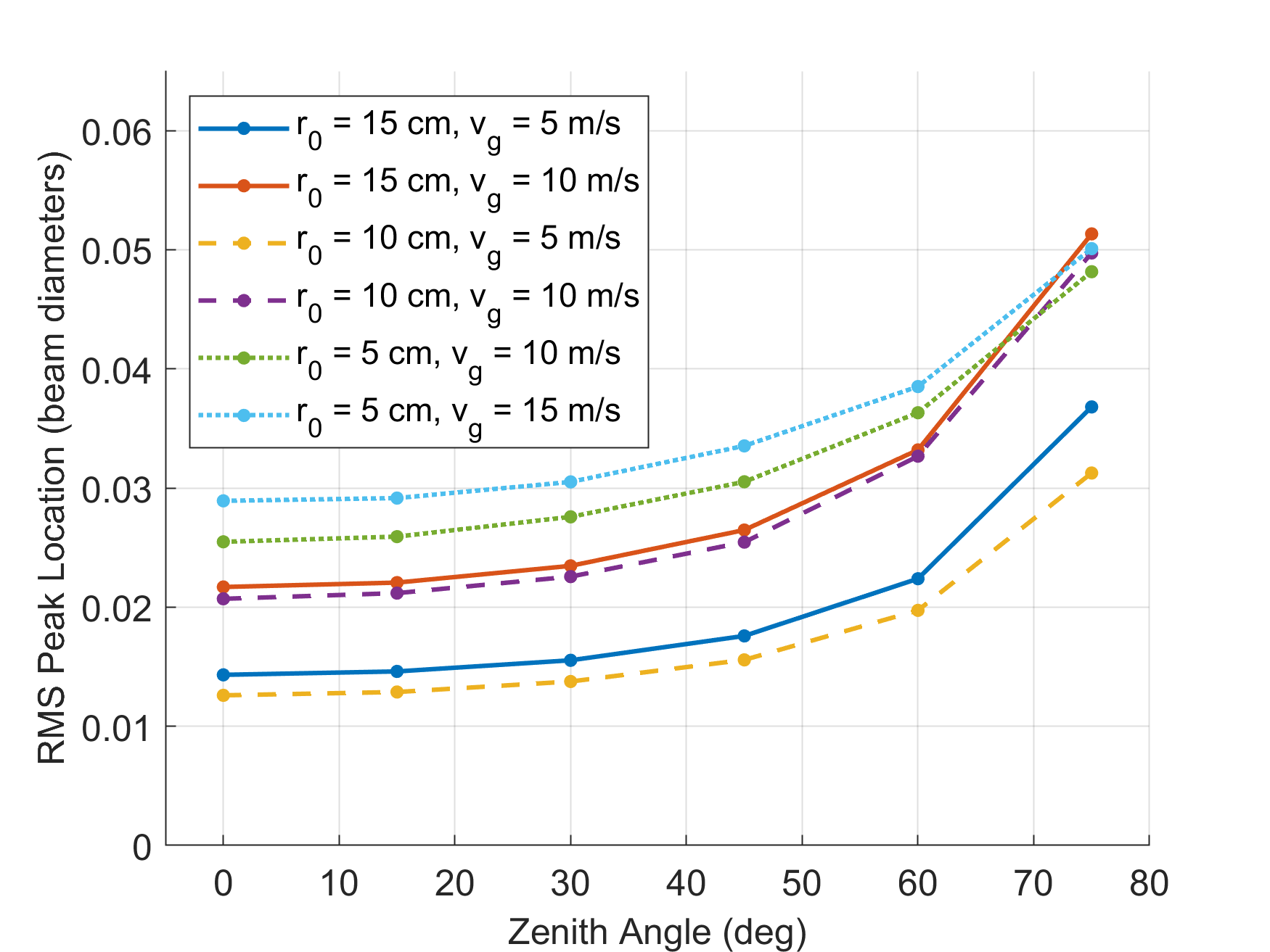
The root-mean-square peak location as a function of zenith angle for each atmospheric condition is plotted in Fig. 8. There is not a clear, intuitive relationship between and the magnitude of drift, as it is a function of both the strength and spatial structure of the residual phases. The beam drifts more as the linear component of the residual phase profile increases, which in some cases may be less prominent in higher turbulence than in lower turbulence. For a given atmospheric turbulence structure, however, the beam drifts more as both wind speed and zenith angle increase, as one might expect.
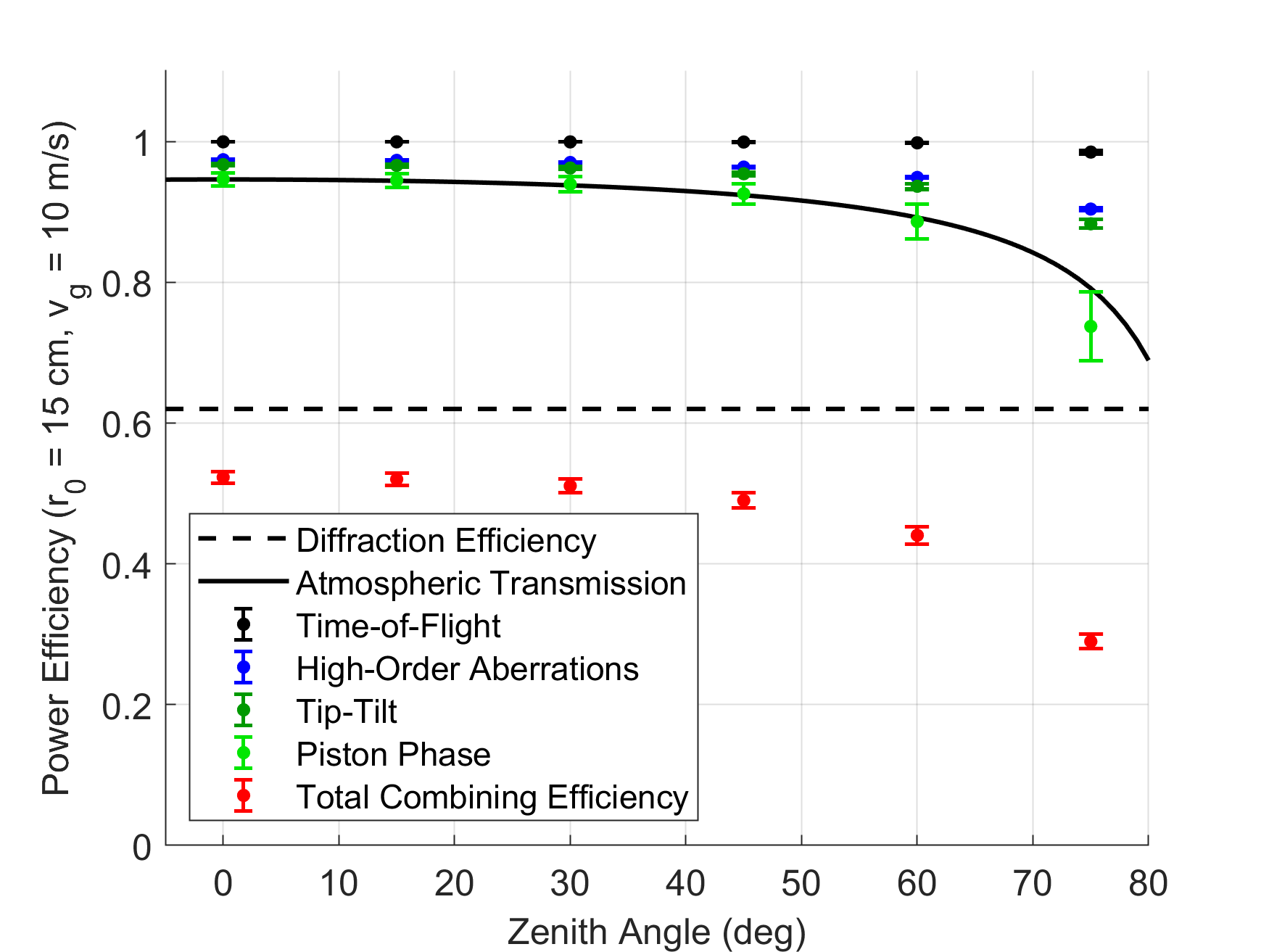
It is instructive to analyze how each of the loss mechanisms in the simulation individually affect the DEPA’s performance. Fig. 9 plots the contributing power efficiency loss factors for the = 15 cm, = 10 m/s case as a function of zenith angle. Black items are fundamental losses which cannot be improved. High order aberrations, in blue, may be mitigated by decreasing the sub-aperture size. Piston phase and tip-tilt efficiency, in green, may be increased with further hardware and servomechanism development. Since the subelements are modular, all losses besides piston phase are applicable to any array size.
5 Scaling to larger arrays
With use of identical, modular subelements, it is expected that piston phase losses are the only thing that will change as a function of array size. Maintaining good phase integrity may be difficult for larger systems, as the closed loop bandwidth of SPGD is inversely proportional . Long fiber baselines will also add phase noise [16]. However, since the proposed DEPA system can be built with nested splitting/combining junctions between the master oscillator and the sub-apertures, it is compatible with a nested SPGD configuration [17]. Nesting may be accomplished by running SPGD in parallel with a detector at every junction, exponentially increasing the system’s closed loop bandwidth for a given acquisition frequency and number of subelements. For example, if the subelements are nested in a 5-deep tree, over one billion can be phased together with only 64 sources at each junction. A demonstration that such a configuration can overcome the expected phase perturbations would suggest that kilometer scale systems placed at high altitude sites are capable of producing diffraction limited spots through the atmosphere.
6 Conclusion
Detailed dynamic beam propagation simulations of a directed energy phased array transmitting through atmosphere in conditions common to astronomical sites were performed using realistic system noise derived from laboratory measurements. A recently developed beam propagation code optimized via parallelization for very large numbers of elements (>) in the array made the simulation of a various scenarios possible. The results provide evidence that large aperture () ground based systems at near-infrared wavelength are capable of producing a stable diffraction limited spot in outer space if the atmosphere has 10 cm (at 500 nm wavelength and zenith angle = 0 deg) and zenith angles 60 deg. These conditions are often satisfied at current astronomical quality high altitude ground based sites. With the success of nested SPGD and the option to add an arbitrary number of subelements, such systems would overcome the size and power limits of current coherent directed energy technology and enable the delivery of high flux beams over vast distances. This development would enable transformational capabilities such as powering lunar bases or propelling spacecraft for rapid interplanetary travel, ablation of incoming asteroids, and even direct photon momentum transfer to enable the first relativistic spacecraft thus enabling interstellar flyby robotic missions [2]. Similar technology may also be used for terrestrial applications such as powering of ground-based remote sensors and rovers in inhospitable locations, remote sensing LIDAR, laser machining, and matter in extreme EOS (equation of state) conditions.
Funding
Funding for this program comes from NASA grants NIAC Phase I DEEP-IN – 2015 NNX15AL91G and NASA NIAC Phase II DEIS – 2016 NNX16AL32G and the NASA California Space Grant NASA NNX10AT93H as well as a generous gift from the Emmett and Gladys W. fund.
Acknowledgments
PML acknowledges support from the Breakthrough Foundation as part of the Starshot program.
Disclosures
The authors declare no conflicts of interest.
Data availability
Data underlying the results presented in this paper are not publicly available at this time but may be obtained from the authors upon reasonable request.
See Supplement 1 for supporting content.
References
- [1] M. N. Zervas and C. A. Codemard, “High power fiber lasers: A review,” \JournalTitleIEEE Journal of Selected Topics in Quantum Electronics 20, 219–241 (2014).
- [2] P. Lubin, “A roadmap to interstellar flight,” \JournalTitleJournal of the British Interplanetary Society - JBIS 69, 40–72 (2016).
- [3] P. Lubin and W. Hettel, “The path to interstellar flight,” \JournalTitleActa Futura 12, 9–44 (2020).
- [4] “The sites | gemini observatory,” https://www.gemini.edu/observing/telescopes-and-sites/sites#0.9-2.7um.
- [5] W. Hettel, P. Meinhold, P. Krogen, and P. Lubin, “Beam propagation simulation of large phased laser arrays,” in Laser Beam Shaping XIX, vol. 11107 A. Dudley and A. V. Laskin, eds., International Society for Optics and Photonics (SPIE, 2019), pp. 153 – 165.
- [6] B. L. Novotny and B. Hecht, “Angular spectrum representation of optical fields,” in Principles of Nano-Optics, (Cambridge University Press, 2012), pp. 39–40.
- [7] A. Reeves, “Soapy: an adaptive optics simulation written purely in Python for rapid concept development,” in Adaptive Optics Systems V, vol. 9909 E. Marchetti, L. M. Close, and J.-P. Véran, eds., International Society for Optics and Photonics (SPIE, 2016), pp. 2173 – 2183.
- [8] M. Schöck, S. Els, R. Riddle, W. Skidmore, T. Travouillon, R. Blum, E. Bustos, G. Chanan, S. G. Djorgovski, P. Gillett, B. Gregory, J. Nelson, A. Otárola, J. Seguel, J. Vasquez, A. Walker, D. Walker, and L. Wang, “Thirty Meter Telescope Site Testing I: Overview,” \JournalTitlePubl. Astr. Soc. Pac. 121, 384 (2009).
- [9] S. Redmond, K. Creedon, T. Y. Fan, A. Sanchez, C. Yu, and J. Donnelly, “Active coherent combination using hill climbing-based algorithms for fiber and semiconductor amplifiers,” in Coherent Laser Beam Combining, (Wiley-VCH, 2013), pp. 103–136.
- [10] L. C. Andrews, R. L. Phillips, and C. Y. Young, “Modeling optical scintillation,” in Laser Beam Scintillation with Applications, vol. PM99 (SPIE Press, 2001), pp. 67–96.
- [11] F. E. Thomas, “The scintillation index in moderate to strong turbulence for the gaussian beam wave along a slant path,” Ph.D. thesis, University of Central Florida (2005).
- [12] H. G. Booker, J. A. Ferguson, and H. O. Vats, “Comparison between the extended-medium and the phase-screen scintillation theories,” \JournalTitleJournal of Atmospheric and Terrestrial Physics 47, 381–399 (1985).
- [13] L. C. Andrews and R. L. Phillips, “Propagation through random phase screens,” in Laser Beam Propagation through Random Media, Second Edition, (SPIE, 2005), pp. 648–666.
- [14] M. Born and E. Wolf, Principles of Optics, 5th ed. (Pergamon Press, 1975).
- [15] A. Brignon, J. Bourderionnet, C. Bellanger, and J. Primot, “Collective techniques for coherent beam combining of fiber amplifiers,” in Coherent Laser Beam Combining, (Wiley-VCH, 2013), pp. 137–165.
- [16] P. Srinivasan, P. Krogen, P. Meinhold, W. Hettel, O. Ou, P. M. Lubin, N. Blasey, and G. B. Hughes, “Beamed-energy propulsion: optical phase noise in 1064nm fiber amplifiers ,” in Optical Modeling and Performance Predictions X, vol. 10743 M. A. Kahan and M. B. Levine-West, eds., International Society for Optics and Photonics (SPIE, 2018), pp. 99 – 108.
- [17] G. D. Goodno, E. Cheung, and W. H. Long, “Nested loop coherent beam combining system,” (2014). US8837033B2.