Free-form Design of Discrete Architectural Surfaces
by use of Circle Packing
Abstract
This paper presents an efficient approach for the conceptual design of architectural surfaces which are composed of triangular panels. In the free-form design of discrete architectural surfaces, the Gaussian curvature plays an important role not only aesthetically but also in terms of stiffness and constructability. However, designing a surface manually with specific Gaussian curvatures can be a time-consuming task. We propose a method to find a triangulated surface with user-specified Gaussian curvatures (not limited to constant Gaussian curvatures) and boundary vertex positions. In addition, the conformal class of the final design can be specified; that is, the user has control over the shape (the corner angles) of each triangular panel. The panels could be encouraged to form a regular tessellation or kept close to those of the initial design. The controllability of the conformal class suppresses possible distortion of the panels, resulting in higher structural performance and aesthetics.
Our method relies on the idea in computational conformal geometry called circle packing. In this line of research, the discrete Ricci flow has been widely used for surface modelling. However, it is not trivial to incorporate constraints such as boundary locations and convexity of the spanned surface, which are essential to architectural applications. We propose a perturbation of the discrete Ricci energy and develop a least-squares-based optimisation scheme to address these problems with an open-source implementation111Our codes are publicly available at https://github.com/shizuo-kaji/ricci_flow.
Keywords— geometry processing; surface modelling; computational conformal geometry; architectural surfaces; Gaussian curvature; circle packing.
1 Introduction
Upon the rapid development in digital technology, free-form surfaces have found their progressively important position in many fields such as product design, ship building, and architecture. Tools have been developed for the creation of digital models, where surfaces designed by artists are algorithmically modified to meet practical and aesthetic requirements while retaining the qualities of the original surfaces including the artists’ design intent (e.g., [19]). In the field of architecture, architectural geometry [23] aims to solve complex and challenging problems in designing architectural surfaces under various geometric and structural constraints by combining knowledge from differential geometry, computational geometry, and architectural design and engineering.
Most of the modern architectural surfaces are intrinsically discrete, with only a few exceptions that are truly continuous such as membrane and concrete shell structures. The geometry of discrete surfaces has been extensively studied in the field of discrete differential geometry [7] and computational conformal geometry [13], One of the pioneering work utilising computational conformal geometry in architecture is [26], where the idea of circle packing is used to create triangular meshes whose incircles form a circle packing on the surface. Another prominent example is [27], which develops approximation of surfaces by curvature-aligned rectangular panels.
A prevalent idea employed by many geometric methods is to formulate the problem of finding surfaces with specified design targets as variational problems with certain energy functionals. Among the design targets involving geometric property of a surface, the Gaussian curvature serves one of the most important indices. This preference relies not only on aesthetics but also on stability (stiffness), which are two of the three design principles222The third design principle is functionality. advocated by Vitruvius (15 B.C.) and accepted by most prominent architects. In the aesthetic aspect, curved lines and surfaces are more harmonious, relaxing, and pleasant, because human preference for curvature is biologically determined [11]. The architectural surface or facade is of course not an exception as investigated in [25]. In the stability aspect, larger curvature generally leads to higher stiffness. For instance, the Guggenheim Museum makes use of the ever-present curvature of the various geometries, not only for aesthetic purpose but also to significantly enhance stiffness of the structure against lateral loads [16]. In the past decades, double curvature structural envelopes (that is, non-developable surfaces) have become increasingly popular in architectural design.
It is usually desirable to have gradually varying curvature, if not constant, over the surface, in order to present its elegant appearance and to avoid sudden change in stiffness distribution. It is, however, challenging to design surfaces manually that have specified Gaussian curvatures within a marginal error allowed by constructability requirements. One designing principle is to specify the boundary of the surface and a rough (expected) shape that spans the boundary, and rely on an algorithmic technique to find the final surface numerically. For example, a numerical form-finding method was presented based on the generation of linear Weingarten surfaces [31]. This method allows to build the surfaces on a target boundary curve but does not allow the user to specify the Gaussian curvatures of the interior vertices explicitly. Another method is proposed to obtain a surface with user-specified Gaussian curvatures based on the Gaussian curvature flow [38]. However, it is shown to be highly unstable. Furthermore, the shape of the panels could be distorted in the obtained surface even when the initial surface consists of near-regular panels. Keeping (regular) shapes of the panels is important to aesthetic appearance of the surface and to structural performance. To preserve the angles of the panels of the initial surface, Ricci flow-based333In dimension two, the Ricci flow coincides with the Yamabe flow and these names are used interchangeably. methods have been developed [18, 35, 37, 17], which find final surfaces conformal to the initial one (see [36] for a survey). However, existing applications of Ricci flow-based algorithms mainly focus on flattening surfaces to have the constant Gaussian curvatures at all vertices (e.g., [28]). This agrees with the fact that the Ricci flow is closely related to the uniformisation theorem [14]. Furthermore, existing Ricci flow-based algorithms do not pay much attention to imposing constraints such as boundary locations and convexity (or concavity) of the resulting surface, which are relevant to architectural applications. A mesh editing technique developed in [33] finds a near-conformal mesh satisfying positional constraints by minimising an energy functional measuring the deviation of two meshes from conformally equivalent. However, it is not straightforward to prescribe curvatures with this method.
These problems in designing discrete architectural surfaces motivate us to present an efficient tool for quick conceptual design, which “finetune” the initial surface to one with user-specified Gaussian curvatures and boundary vertex locations within a user-specified conformal class. The user can focus on the rough design of the surface, and our system turns the surface automatically to one that meets curvature, boundary, and panel shape requirements. Our flexible framework allows the user to incorporate other constraints as well. As an example, finding a convex surface with user-specified Gaussian curvatures is demonstrated.
After the introduction, this paper is organised as follows: Section 2 describes the background of discrete surfaces and circle packing on them. Section 3 discusses the algorithmic details of our method. Section 4 presents numerical examples to validate the proposed approach and demonstrate its versatility for the free-form design of discrete surfaces. Section 5 concludes the study with limitations of the proposed method and visions of future works.
2 Overview of discrete conformal surface geometry
This section provides an overview of the surface modelling based on computational conformal geometry. We put a particular emphasis on various geometric structures on discrete surfaces and their hierarchy. Although we often use the terminology in differential geometry to evoke analogy, we do not rely on the knowledge of differential geometry, and we give a definition to each notion relevant in our setting.
2.1 Triangulated surface mesh
In this study, we consider surfaces that are triangulated meshes. Triangulated mesh is one of the most popular surface representation with which various mesh processing algorithms have been developed. As our method takes and outputs triangulated meshes, it can be incorporated as a module of the surface design toolchain. There exist algorithms to convert triangular meshes into rectangular ones such as the Catmull–Clark subdivision [4] and [27], which can be applied as the post process of our method. From an architectural perspective, intrinsic mechanical stability of triangles leads to much higher stiffness-to-material ratio compared to other polygonal shapes. Their superiority in lightweightness or material-efficiency enables the triangular meshes to be suitable for free-form architectures. This is in particular the case for the roof structures that span a huge column-free space, when they are utilized as supporting system themselves [21]. The Beijing Daxing International Airport Terminal, jointly designed by the Zaha Hadid Architects, is an excellent example: a grid shell with triangular mesh is used for the free-form roof of the center zone. Due to this unique roof structure, together with other innovations, e.g., the biggest terminal and the largest vibration-isolation building in the world [39], it has won a number of awards and was named as one of the new seven wonders by The Guardian.
An abstract triangulated mesh (a mesh, for short) is composed of the set of vertices, the set of edges, and the set of triangular faces. Here, we have architectural surfaces composed of triangular panels (faces) in mind. The edge connecting two vertices is denoted by , and the face formed by three vertices , , and is denoted by . As we are modelling surfaces, we always assume that the neighbourhood of each vertex is homeomorphic to the plane or the half-plane, and each edge is contained in at most two faces. An edge is said to be interior (resp. boundary) if it is contained in two faces (resp. a single face). The set of boundary edges is denoted by . The vertices contained in boundary edges are called boundary vertices, and the set of boundary vertices is denoted by .
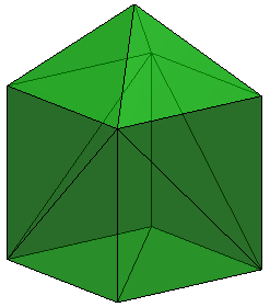
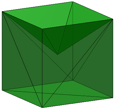
A mesh is a combinatorial object and retains only the topology of the surface; that is, no information on lengths, areas, vertex positions are associated. The information on sizes can be bestowed by edge lengths ; an assignment of non-negative number for each edge . Since faces are triangles, we demand the edge lengths to satisfy the triangular inequality for any face . In this case, we say the edge lengths define a discrete Riemannian metric (a metric, for short) on a mesh. Note that the edge lengths completely determine the shapes of the triangle faces, but not the dihedral angles between them; one may build more than one surfaces with the same set of panels (see Fig. 1).
The Gaussian curvature at a vertex quantifies the deviation of the neighbourhood of the vertex from a plane. There are several (non-equivalent) definitions of Gaussian curvatures for a mesh with a metric. In this paper, we adopt the angle defect as their definition. Namely, the Gaussian curvature at vertex is defined as follows:
| (1) |
where is the corner angle at vertex in the face . The Gaussian curvatures are constantly zero for any triangulation of the flat plane and surfaces foldable from it (imagine edges work as hinges). The Gaussian curvatures of a mesh are computed solely from its metric independent of the coordinates of its vertices; such a geometric property is said to be intrinsic. That is, intrinsic properties of a surface are determined by the shape of its constituent panels and how they are connected each other regardless of the location (coordinates) of the panels. Thus, intrinsic properties are preserved when the initial surface is folded to another one without changing the shape of its faces.
Although a metric determines the local shape of a mesh, its global realisation as a surface in space is not specified merely by a metric. An embedding of a mesh assigns the coordinates to each vertex . Fig. 1 shows an example of two embeddings of a mesh with a metric; that is, two surfaces constructed from the same panels with the same connection among them. They have the same edge lengths, and hence, the same Gaussian curvatures. We call a mesh together with an embedding design or geometry. In summary, a design is specified by or decomposed into three components; a mesh (connection of panels), a metric (shape of panels), and an embedding (location of panels).
2.2 Circle packing on a mesh
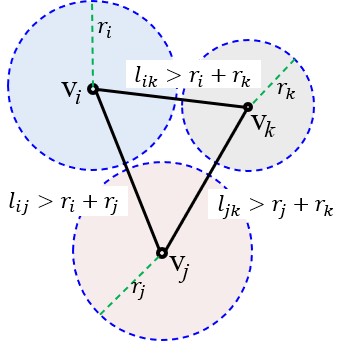
For smooth surfaces, conformal deformations are characterised as deformations that preserve angles. However, a general discrete surface represented by a triangulated mesh cannot be deformed to a non-similar one without changing the corner angles of the triangles. Obviously, we need more flexibility to design architectural surfaces. To avoid this rigidity (or locking) problem, we need a different notion of conformality in the discrete setting. There are several non-equivalent definitions of conformality of discrete surfaces (see, e.g., [8, 1]), we rely on Thurston’s idea [32] to look at circle packing. Under a conformal deformation of a smooth surface, the intersection angles of infinitesimal circles covering the surface do not change. In analogy, for a triangular mesh, we consider a circle packing in which a circle of finite radius is assigned to each vertex . Colloquially, a deformation is conformal if it does not alter the intersection angles of the circles (this analogy is made precise in [24]). The intersection angle (see Fig. 2(a)) between the circles at vertices and is computed by:
| (2) |
where and are connected by an edge . Thurston’s circle packing of a mesh additionally assumes that the circles intersect with non-obtuse angles . However, it is not easy to find Thurston’s circle packing in practice for a given mesh with a metric. Hence, we rely on a relaxed and abstract notion of conformal structure on a mesh, which is an assignment of for each edge . For a Thurston circle packing, we define . We also allow “non-intersecting” circle packing, which is called the inversive distance circle packing [2], as in Fig. 2(b).
 |
 |
|
| (a) Thurston’s circle packing | (b) general circle packing |
For a mesh with a circle packing and a conformal structure , a metric can be associated by
| (3) |
From this relation, a conformal structure together with a circle packing determines a metric. By rewriting the formula, we see a metric together with a circle packing determine a conformal structure analogiously to (2):
| (4) |
A deformation that preserves the discrete conformal structure is called a conformal deformation.
For a given mesh with a metric, there are several heuristic ways to define a circle packing radius at vertex from the metric. A popular choice [2] is given by
| (5) |
Alternatively, we can ignore the metric, and set for all , which would correspond to the conformal structure of a regular tessellation.
2.3 Constraint on Gaussian curvature
The primary goal of this paper is to find an embedding of a mesh that achieves user-specified Gaussian curvatures. We would like to recall the fact that the Gaussian curvatures cannot take arbitrary values but are constrained by the mesh topology and geometry. First, the Gauss-Bonnet theorem imposes the topological constraint:
| (6) |
where is the Euler characteristic of the mesh. Second, the conformal structure imposes the geometric constraint [6, 18]: For any proper subset ,
| (7) |
where is the set of the faces whose vertices are in , and is the link of .
2.4 Metric deformation of a mesh
As a Riemannian metric determines the Gaussian curvatures of a smooth surface, a metric on a mesh (edge lengths) determines the corner angles of the triangular faces by cosine law, and in turn, the Gaussian curvatures of its vertices. To find a metric having the user-specified Gaussian curvatures, the Ricci flow can be utilised. The Ricci flow for discrete surfaces was established by [6] in analogy to its smooth counterpart introduced in [14]. It was shown that under a mild condition, the discrete Ricci flow converges quickly to give a metric having the specified Gaussian curvatures while preserving the conformal structure. As our method is closely related to the discrete Ricci flow, we give a brief description of it. We refer the reader to [36] for details of the discrete Ricci flow.
With a fixed mesh with a fixed discrete conformal structure, we are to find such a metric that gives a Gaussian curvature close to a user-specified one at each vertex . The key point is that we deform the circle radii instead of directly deforming the metric or the vertex positions. Recall that with a fixed conformal structure , the metric is reconstructed by the circle radii by (3). The strategy of deforming the circle radii instead of the edge lengths has two advantages. First, one can specify the conformal class of the metric. Second, edge lengths obtained by (3) automatically satisfy triangular inequality so that we do not have to care the space of feasible solutions.
Denote the vector by , where . Given a prescribed Gaussian curvature for each vertex , the Ricci energy is defined by
| (8) |
where is the null vector. The integral does not depend on the path as the integrand can be shown to be an exact form. It is proved in [6] that when satisfy (7), the Ricci energy is strictly convex on the space , which amounts to fixing the indeterminacy of the uniform scaling. The discrete Ricci flow is the negative gradient flow of the Ricci energy, which is calculated as
| (9) |
Under the conditions (6) and (7), the Ricci energy attains its global minimum when , which means for all .
While the Ricci flow provides a powerful method for mesh deformation backed with a theoretical guarantee, there are some difficulties when one tries to apply it for practical problems. While the gradient of the Ricci energy has a simple closed-form expression (2.4), its value itself is defined by an integral (2.4). This hinders the use of most of modern optimisation techniques such as trust region which require the evaluation of the target function value. Our idea is to modify the Ricci energy so that it admits a closed, least-squares form, which allows us to use well-established solvers and to incorporate various constraints such as boundary positions and convexity. We propose the modified Ricci energy defined by
| (10) |
where is a subset of vertices on which we would like to specify their Gaussian curvatures (typically, the set of interior vertices is chosen). The above mentioned properties of the Ricci energy guarantee that there exists a unique which realises the global minimum when and satisfy (6) and (7). We cannot, however, assert that there are no other local minima. The gradient of (10) is easily computed as
where is given, e.g., in [18].
3 Implementation of our method
In the previous section, we summarised how various properties are determined on the surface as functions of other properties. A mesh defines the topology and serves as a container of geometric structures. It carries the information on the number of triangle panels and how they are connected. A metric is a function specifying the edge lengths , which determines the shape of each panel. An embedding is a function specifying the vertex coordinates , that is, how each panel is placed. The Gaussian curvatures are solely determined by the metric (the panel shape) independent of an embedding. Therefore, to obtain a surface with prescribed Gaussian curvatures, we have to find the appropriate metric. Instead of handling the edge lengths directly, we can consider proxy variables. A circle packing is a function specifying the radius of a circle centred at each vertex. A conformal structure together with a circle packing determines a metric. Table 1 summarises the relations among various structures on a mesh.
| mesh | metric | curvature | circle packing | conformal str. | embedding | |||
| (panel connection) | (panel shape) | (angle defect) | (panel location) | |||||
| symbol | ||||||||
|
, or and | (non canonical) | and |
When we would like to control a certain property, say the Gaussian curvature, we can deform upstream properties such as edge lengths and circle packing radii. This allows us flexibility in choosing design variables when the problem is formulated in terms of an optimisation problem.
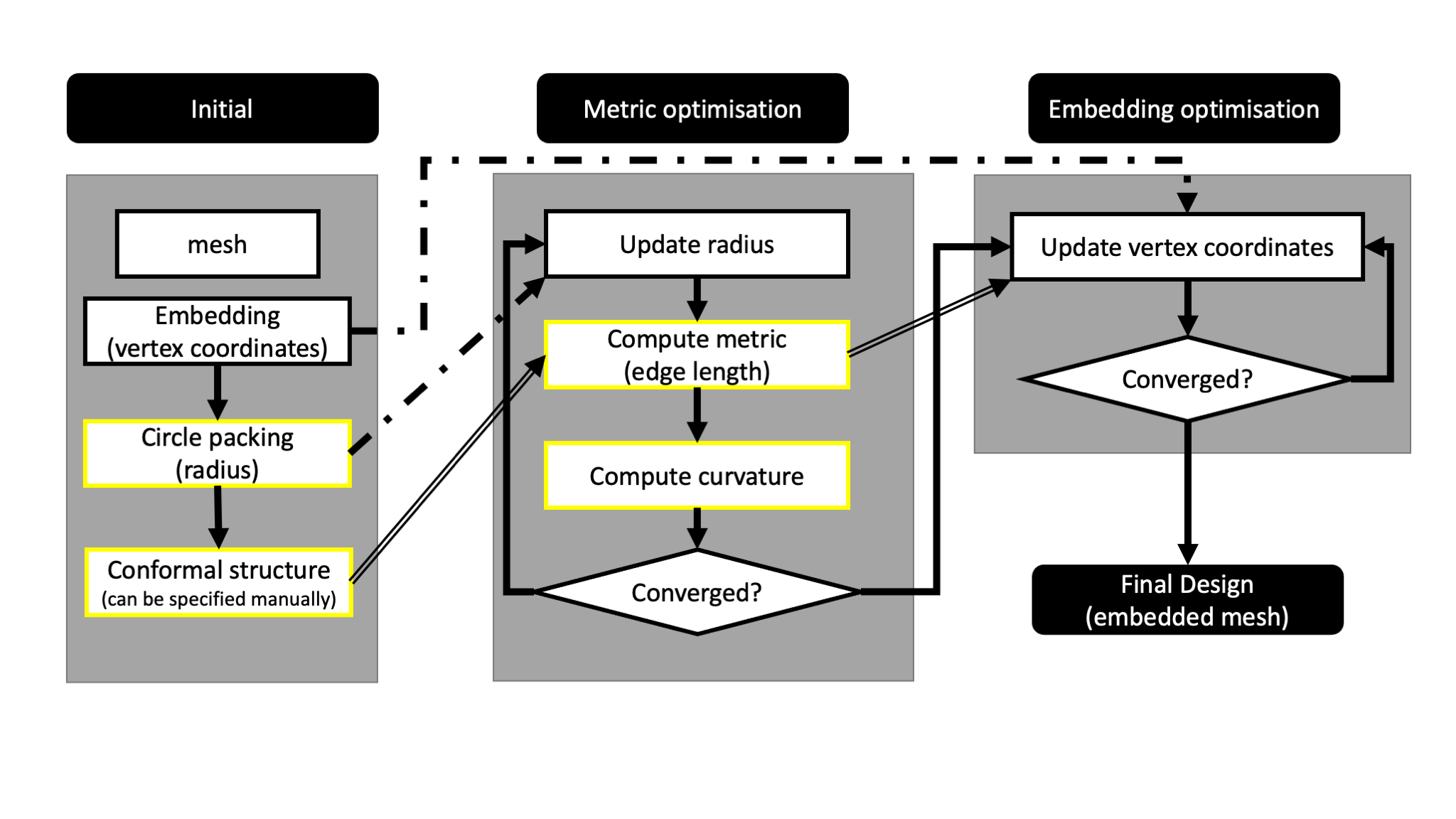
Our proposed method consists of two steps; metric optimisation and embedding optimisation (see Fig. 3). Given a mesh and a conformal structure, the metric optimisation finds a metric having the user-specified Gaussian curvatures and the user-specified lengths on a subset of edges (typically, the set of the boundary edges). This part determines the approximate shape of the panels that are used to construct the final surface. Then, the embedding optimisation finds an embedding having the metric obtained in the previous step and the user-specified coordinates on a subset of vertices (typically, the set of the boundary vertices). This part determines the actual position of each panel. The final design is obtained as the embedded mesh in the Euclidean -space .
3.1 Metric optimisation
Assume that a mesh together with user-specified target Gaussian curvatures on a subset of vertices (typically, the set of interior vertices) is given. Moreover, the user specifies a conformal structure . For example, if the mesh has a uniform vertex valence of six, setting the constant value for all edges encourages the final mesh to have a regular tessellation with equilateral triangular panels. Alternatively, the conformal structure can be computed from the metric of initial design by (5) and (4). In this case, the final mesh will be in the same conformal class as the initial one, and hence, the shape of panels are expected to be preserved. Moreover, the user can specify certain edges to have the specified lengths . For example, if we would like the positions of the boundary vertices fixed to in the final embedding, we set and at this stage.
To achieve these goals, we solve the following non-linear least-squares problem:
| Minimize | (11) |
where the first term is the modified Ricci energy (10), and is computed by (3) and . The hyper-parameter controls the trade-off between conformity to the specified Gaussian curvature and the specified edge lengths. Once are obtained as the solution to (3.1), the metric is computed by (3) with .
Remark 2.
Instead of , we can directly optimise the radii in (3.1). The variable is often called the conformal factor in analogy to the smooth setting. Algorithmically, setting serves as a change of variables to ensure the positivity constraint . We may also directly optimise the edge lengths since is a function of as well. However, we cannot specify the conformal class of the resulting metric. Moreover, ensuring the triangular inequality can be problematic. Our codes implement all these choices; , , and .
3.2 Embedding optimisation
Now, we would like to find an embedding of the mesh which realises the metric obtained in the previous step while a subset of vertices (typically, the boundary vertices) have the user-specified coordinates . The problem is similar to the classical multi-dimensional scaling (MDS) [20] in which an embedding of finite points with a specified distance matrix is sought for. Our embedding problem can be thought of as a generalisation of MDS to graphs where only a subset of pairs have specified distances. For a triangular mesh, there is a sophisticated method proposed in [5], where an isometric immersion of a triangular mesh with prescribed edge lengths is obtained. This method optimises the orientation of each triangle represented by a unit quaternion, and hence, it is difficult to incorporate constraints defined with vertex positions such as the boundary condition. Since the boundary constraints is important for our purpose, we rely on a straightforward algorithm which takes the vertex position directly as its optimisation variable. More precisely, we formulate it as a type of graph embedding problem [3]. What is peculiar to our case is the fact that a uniform scaling will not change the Gaussian curvatures at the vertices. Hence, we introduce a scaling factor and solve the following non-linear least-squares problem444When , we set and do not optimise to avoid the degenerate solution of and for all :
| Minimize | (12) |
where is a hyper-parameter controlling the trade-off between conformity of the Gaussian curvature and the boundary coordinates. Other constraints can be easily incorporated by adding penalty terms to (3.2). For example, to enforce the convexity at internal vertices, we add the following term with a hyper-parameter
| (13) |
where is the -coordinate of and is the mean of the -coordinates of the vertices adjacent to . The sigmoid-weighted linear function [9] penalises , and its gradient is computed by . Another example of a penalty term we can add to (3.2) is
| (14) |
where is the vertex coordinate of the initial design and is the hyper-parameter. This regularisation term encourages the final design stay close to the initial one. More generally, we can combine the boundary constraint term and the regularisation term into a single weighted sum of the form , where is the target coordinate and is the weight for each vertex.
The vertex positions of the initial design are used as the initial solution for the optimisation problem (3.2). Note that finding an embedding which realises the specified metric is not convex, and there can be multiple global minima, as is seen in Fig. 1. In this case, the choice of an initial solution affects the final solution. This problem can be mitigated to some extent by regularising the optimisation by adding, for example, the Laplacian smoothing term to the target function [22].
There exists a metric for a mesh with a conformal structure which realises the specified Gaussian curvature if and only if (6) and (7) are satisfied. Furthermore, when such a metric exists, it is unique up to a uniform scaling. However, there may not exist an embedding which realises the metric [10]. Also, there can be multiple non-congruent embeddings which realise the metric. Therefore, the metric optimisation is theoretically more troublesome, and this part is separated from the whole procedure in our scheme.
4 Numerical examples
| (radian) | (meter) | (degrees) | metric opt. (sec) | embedding opt. (sec) | |
|---|---|---|---|---|---|
| Ex1a | 0.49 | 0.28 | 0.32 | ||
| Ex1b | 0.99 | 0.28 | 0.55 | ||
| Ex1c | 0.13 | 0.60 | 0.26 | ||
| Ex1d | 0.55 | 0.33 | 0.31 | ||
| Ex2 | 0.50 | 0.14 | 0.59 | ||
| Ex3 | 0.54 | 0.24 | 1.87 | ||
| Ex4a | 0.06 | 0.53 | 4.08 | ||
| Ex4b | 0.08 | 0.53 | 8.32 |
In this section, we present several numerical examples to validate the proposed method. We are mainly interested in dome-shaped surfaces with a high structural performance covering a large column-free space. To design a high structural performance covering surface built on a specified boundary, minute control over the Gaussian curvature, panel shape, and the boundary positions is important. We evaluate the results in terms of the mean absolute errors of the Gaussian curvatures, the coordinates of the boundary vertices, and the angles of the faces of the final design against the target values:
| (15) |
where are the target corner angles of the triangular panels, and are those of the final mesh. When a conformal structure is given by an initial design, are the corner angles of the initial mesh. When a conformal structure is specified manually, depends on the mesh topology.
All the experiments are performed by our Python script555https://github.com/shizuo-kaji/ricci_flow using SciPy optimisers [34]. There is a trade-off among above-mentioned evaluation indicators. We can control the trade-off by modifying the hyper-parameters such as , , and stopping criteria for optimisation. We terminate the optimisation steps when the norm of the gradient gets less than . Timing is measured on a MacBook Pro with a M1 core using a single core. The results are summarised in Table 2.
Example 1: CGC surface with a hexagonal plan
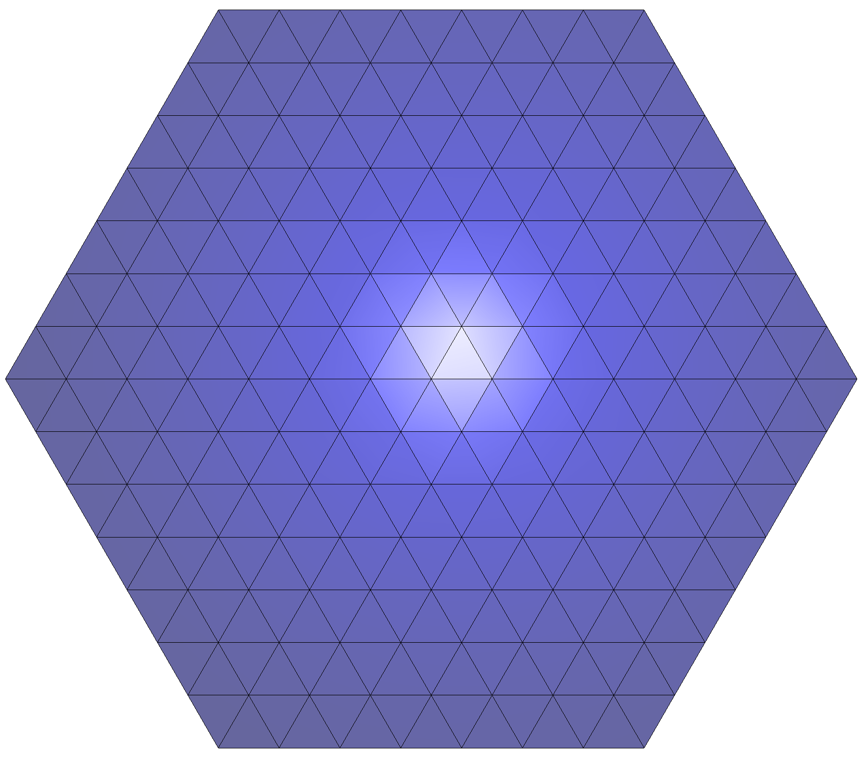
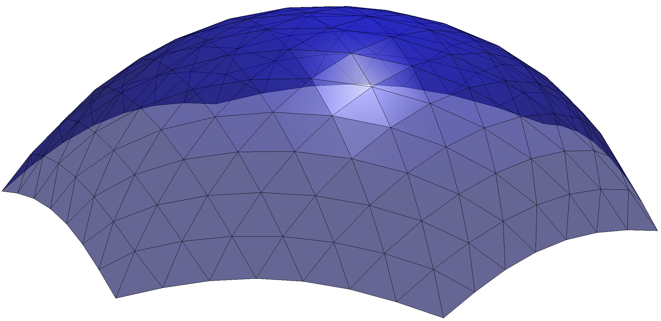
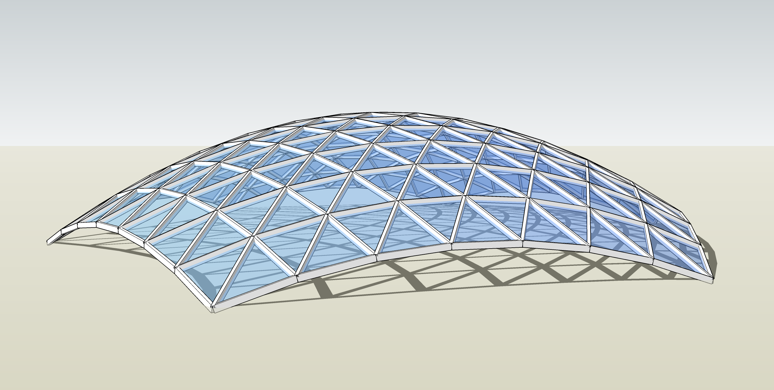
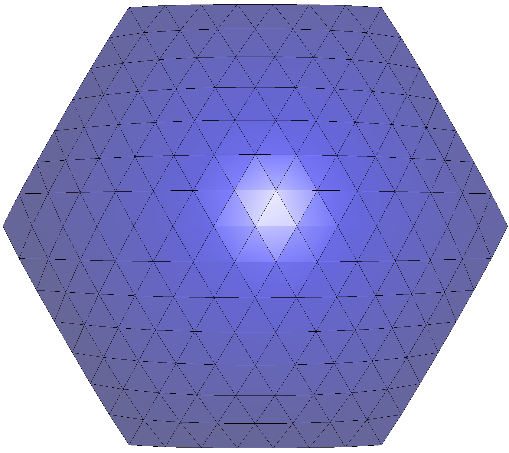
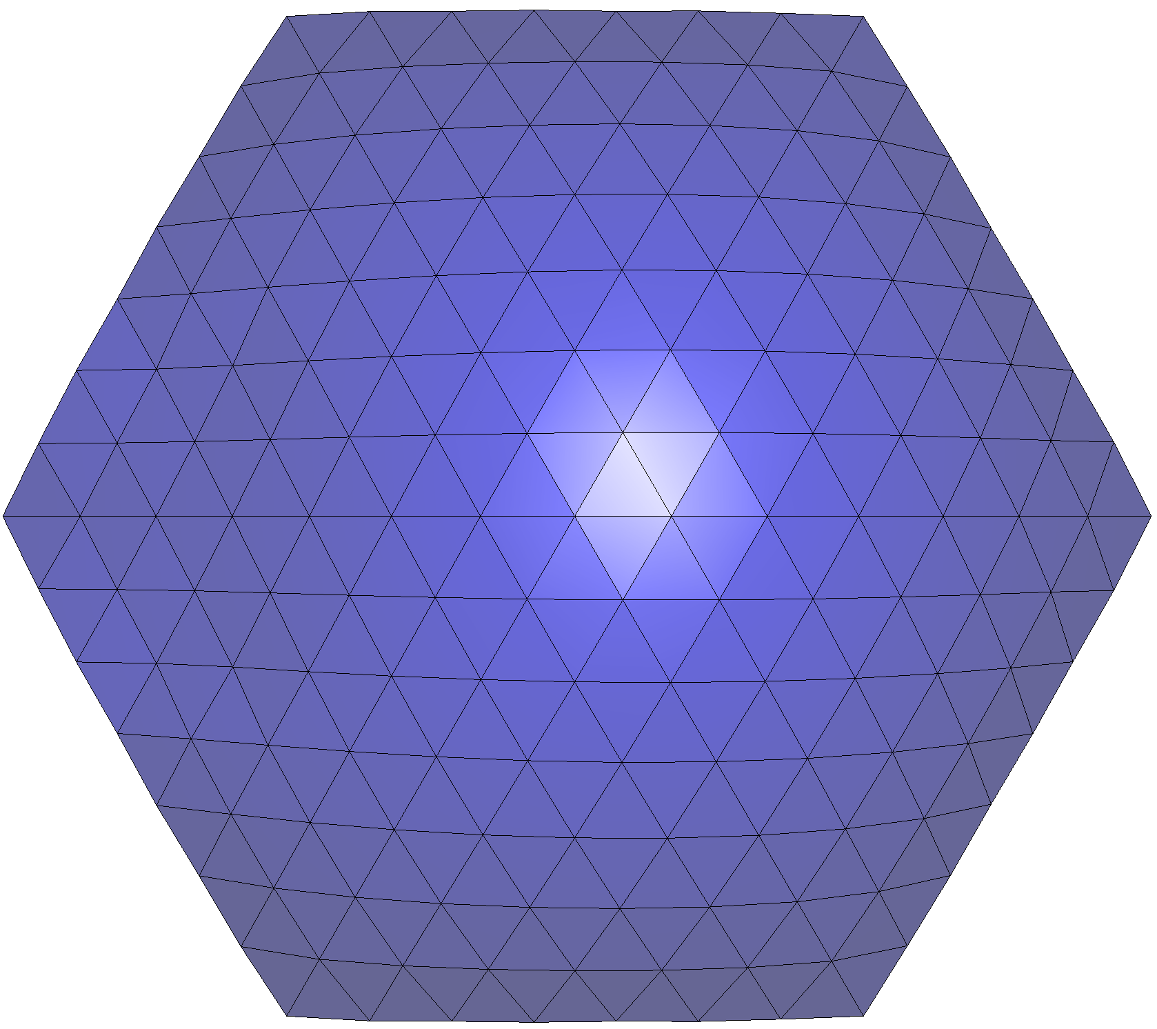
We begin with a simple example of a constant Gaussian curvature (CGC) surface with a hexagonal plan. The initial geometry is shown in Fig. 4. Its span is 30.0m and its height is 10.0m. This surface is composed of 169 vertices (of which 42 are boundary vertices), 462 edges, and 294 faces.
For comparison, we performed several experiments with the same mesh but varying one design target at a time.
-
•
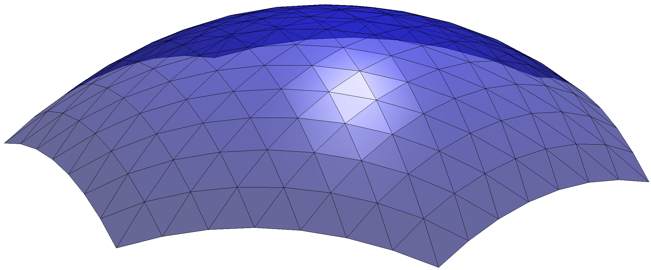
For Ex1a, we set aiming at equilateral panels (that is, ). The total target Gaussian curvature for interior vertices is set to 1.5, and hence, the target Gaussian curvature of each interior vertex is 0.011811. The target positions of the boundary vertices are set to the same as in the initial geometry with .
-
•
In Ex1b, the total target Gaussian curvature for interior vertices is set to 3.0, and hence, the target Gaussian curvature of each interior vertex is 0.023622. Other conditions are the same as Ex1a.
- •
-
•
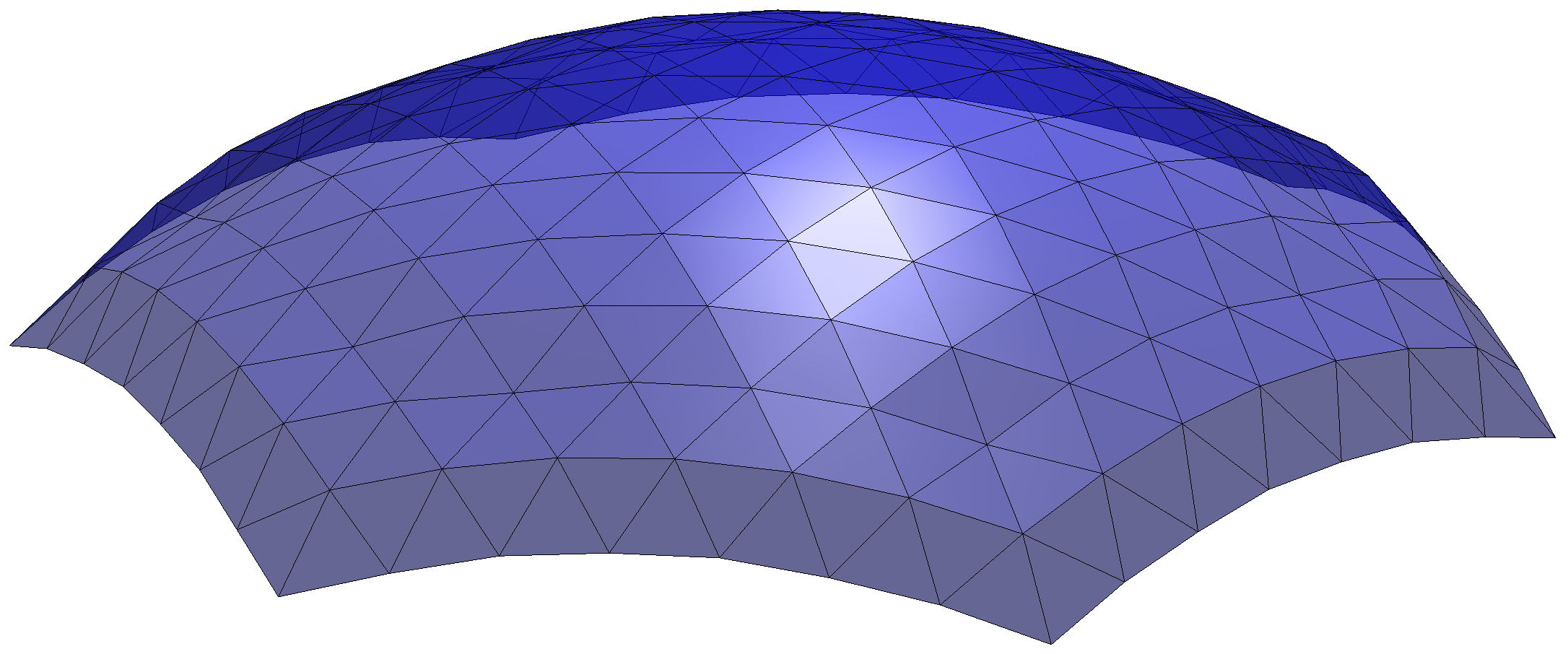
In Ex1d, we set to stress the position condition of the boundary vertices. Other conditions are the same as Ex1a.
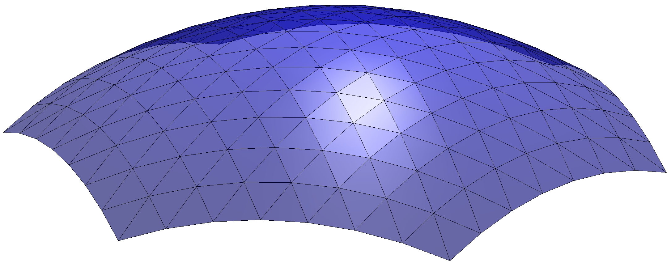
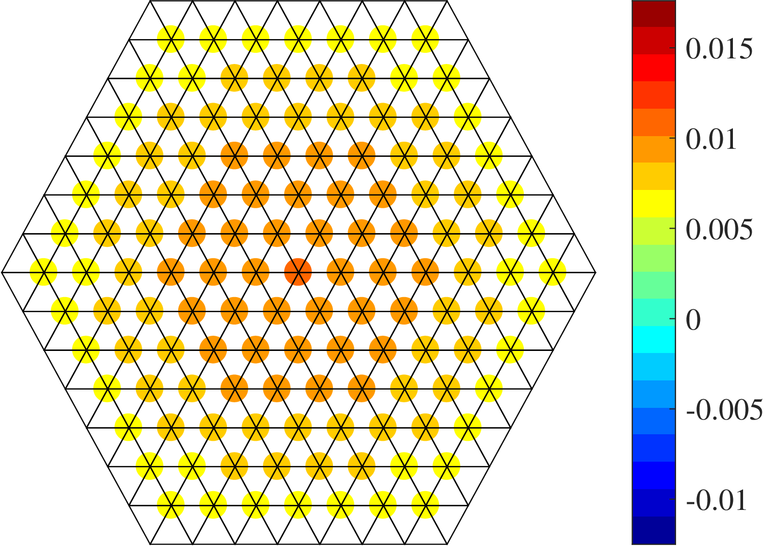
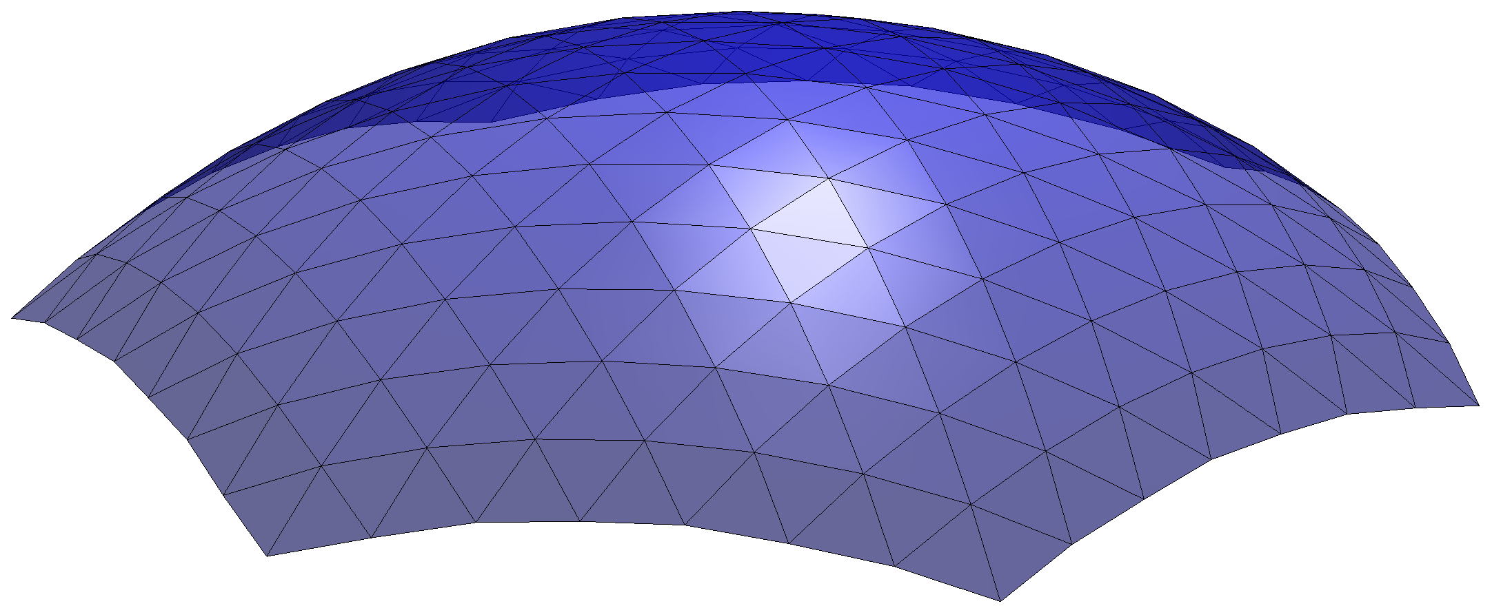
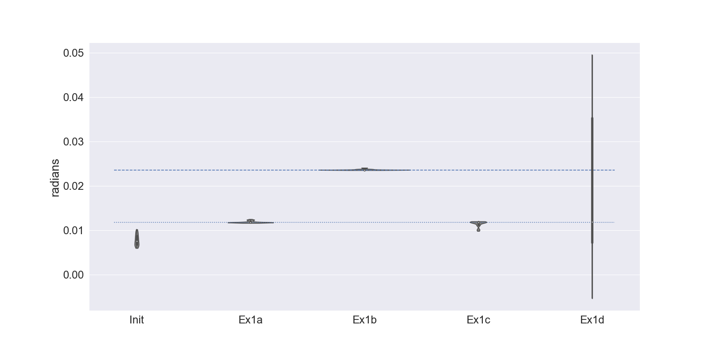
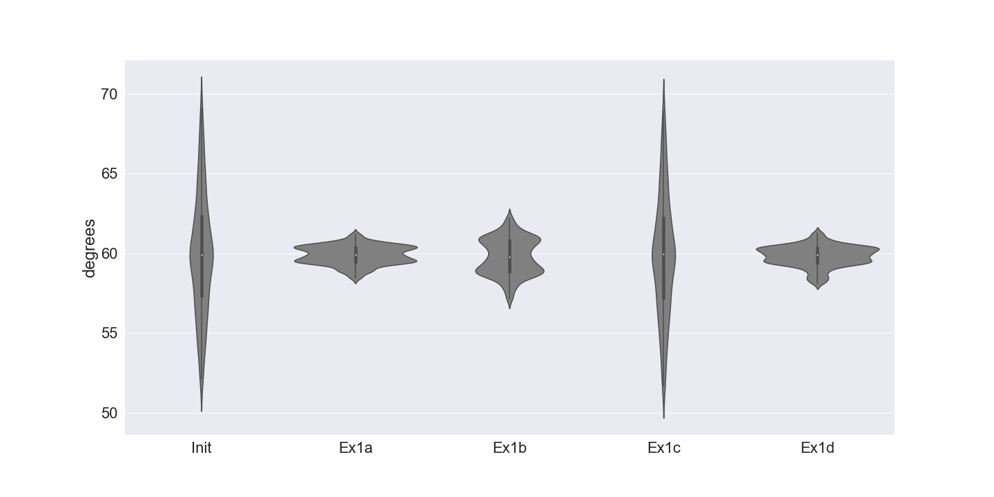
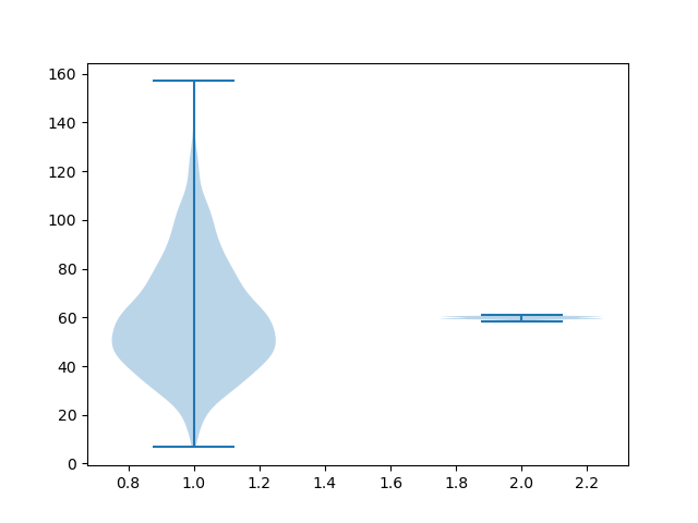
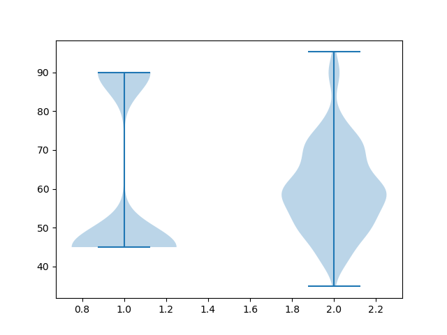
The final geometries are shown in Fig. 5. The distributions of the Gaussian curvatures and the corner angles at interior vertices for the initial and final meshes are shown in the violin plots [15] in Fig. 6.
In Ex1a, Ex1b, and Ex1c, the distributions of the Gaussian curvatures concentrate around the target values. In Ex1d, the stringent constraint increased the precision of the boundary location but this is achieved at a large cost of the precision of the Gaussian curvatures. This suggests that methods which only allow the user to specify the exact boundary locations will fail. Our method offers control over the trade-off through the choice a hyper-parameter.
In the initial geometry, the corner angles of the panels range from 50 to 70 degrees, while in Ex1a, Ex1b, and Ex1d, they are corrected to 60 degrees within 3 degrees of margins, resulting in a near regular tessellation in the final geometry. On the other hand, in Ex1c, the distribution of the corner angles is close to that of the initial geometry as desired.
 |
 |
 |
 |
| Ex1a | Ex1b | Ex1c | Ex1d |
Example 2: surface with irregular mesh
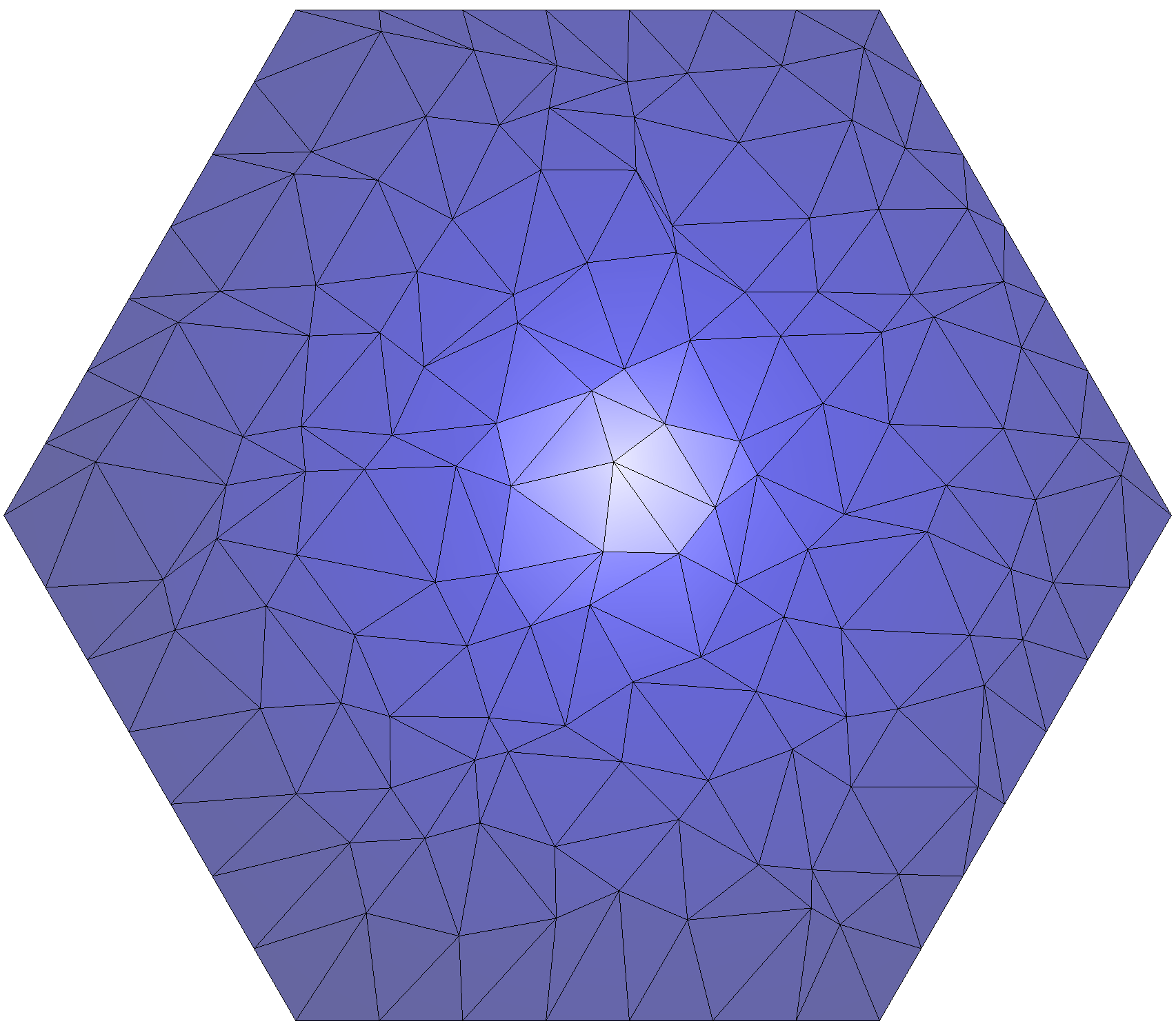
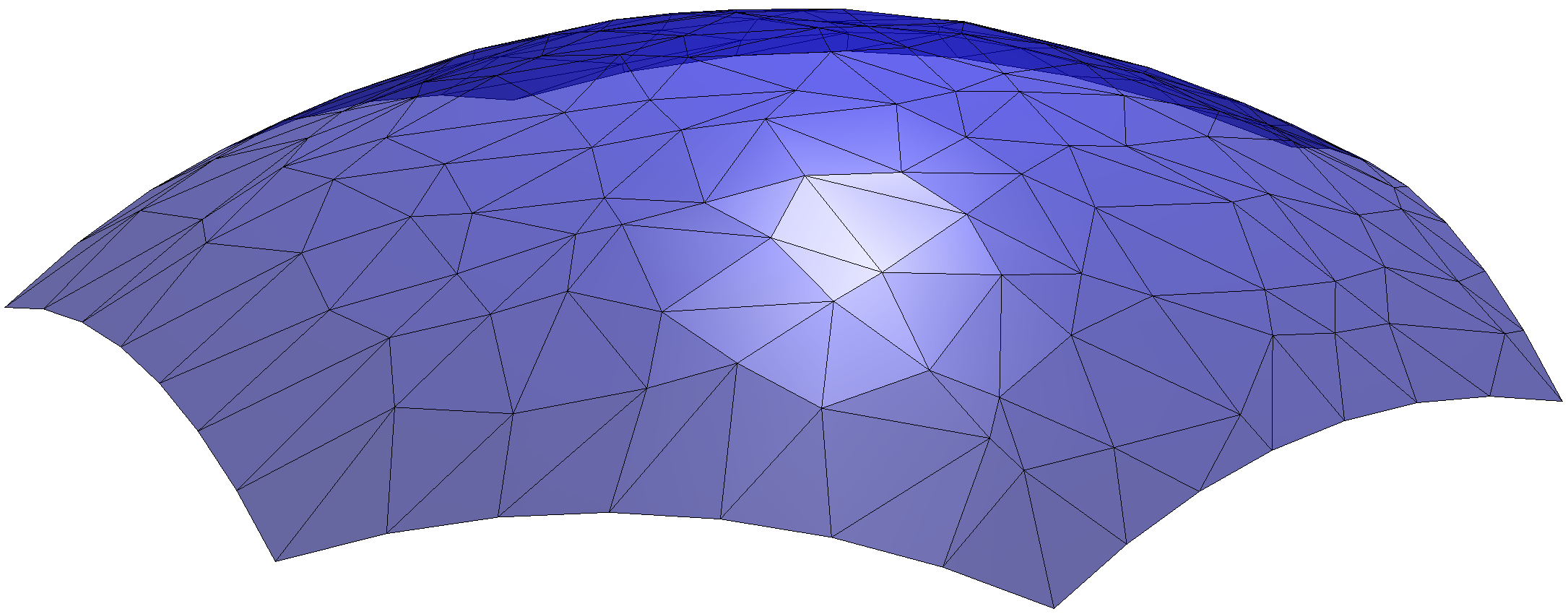
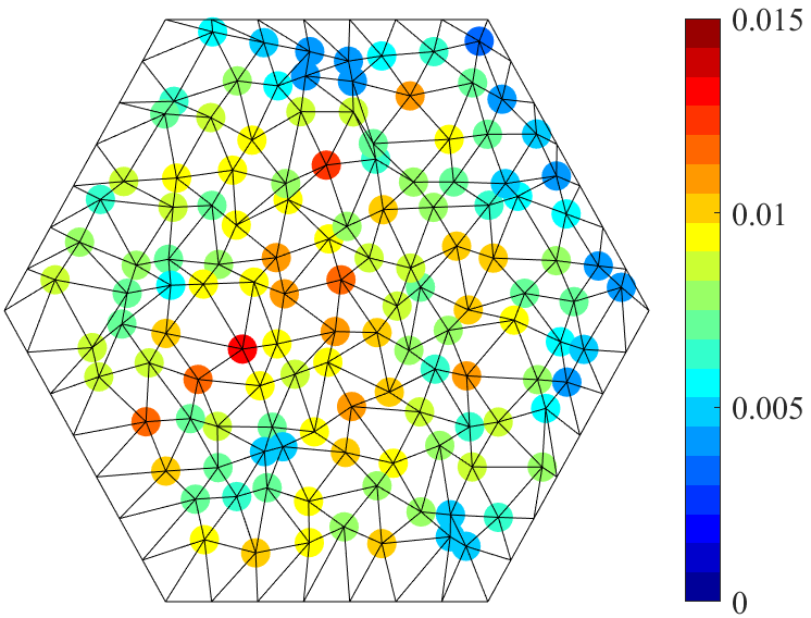
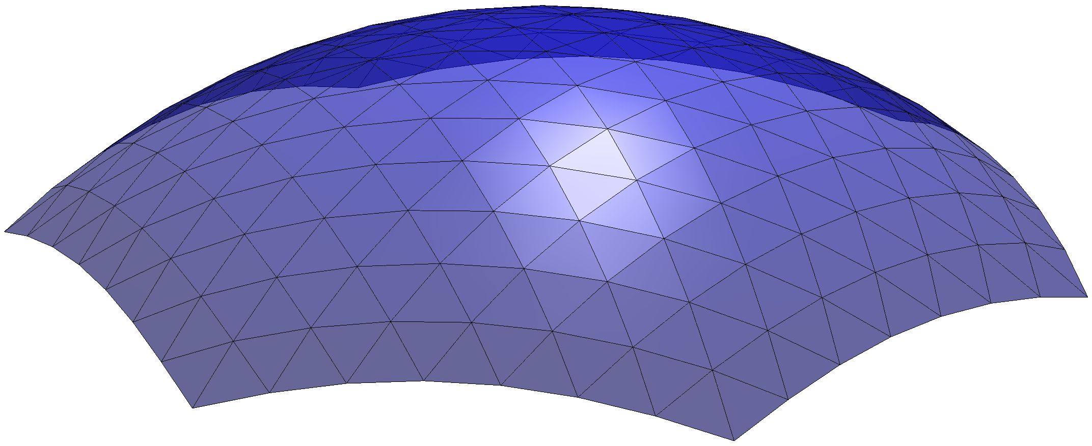
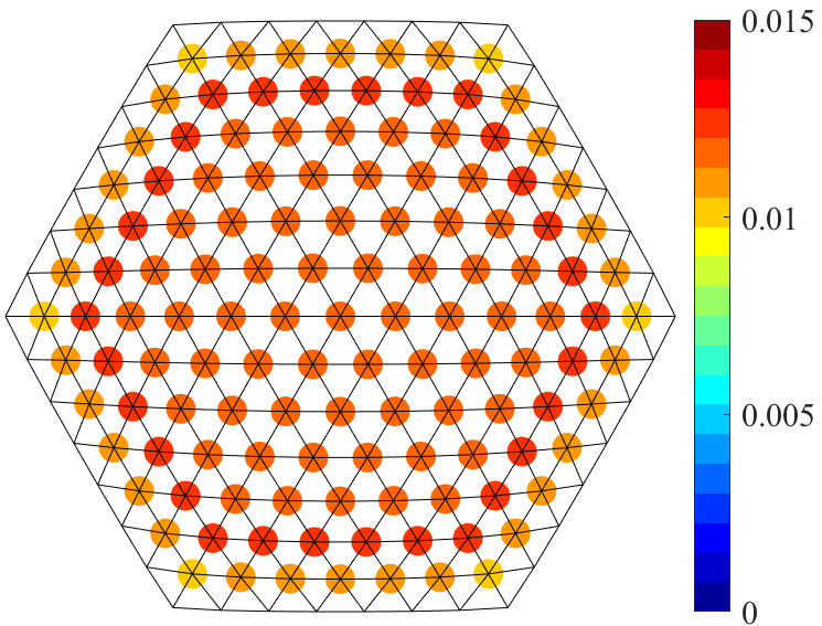
To further illustrate the capacity of the proposed method in transforming an irregular initial mesh into a regular one, we consider the initial geometry as shown in Fig. 8, where the -coordinates of the interior vertices are randomly perturbed from those specified in Example 1. The minimum and maximum Gaussian curvatures at the interior vertices of the initial geometry are respectively 0.0035 and 0.0129. Moreover, the distribution of angles is illustrated in Fig. 9, ranging from about to about .
The parameters of the algorithms are set to the same as Ex1a, except that the coefficient for convexity is set to 0.1. In particular, the target Gaussian curvature of each interior vertex is 0.011811. The final geometry is shown in Fig. 8. The minimum and maximum Gaussian curvatures at the interior vertices of the initial geometry are respectively 0.0101 and 0.0123, which are close to their target values. Moreover, as can also be observed from the angle distribution of the final geometry as in Fig. 9, the mesh becomes nearly regular with almost isosceles triangles.
 |
 |
 |
 |
 |
 |
 |
Example 3: surface with non-uniform Gaussian curvature
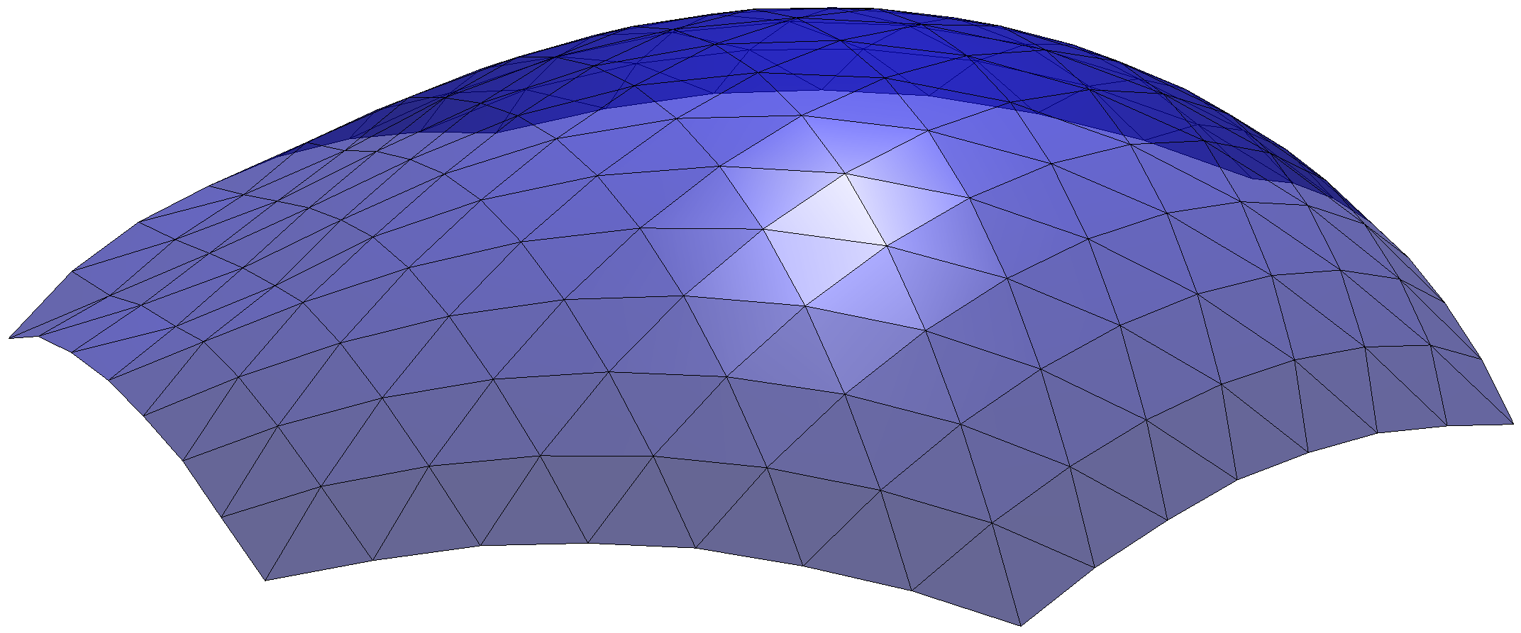
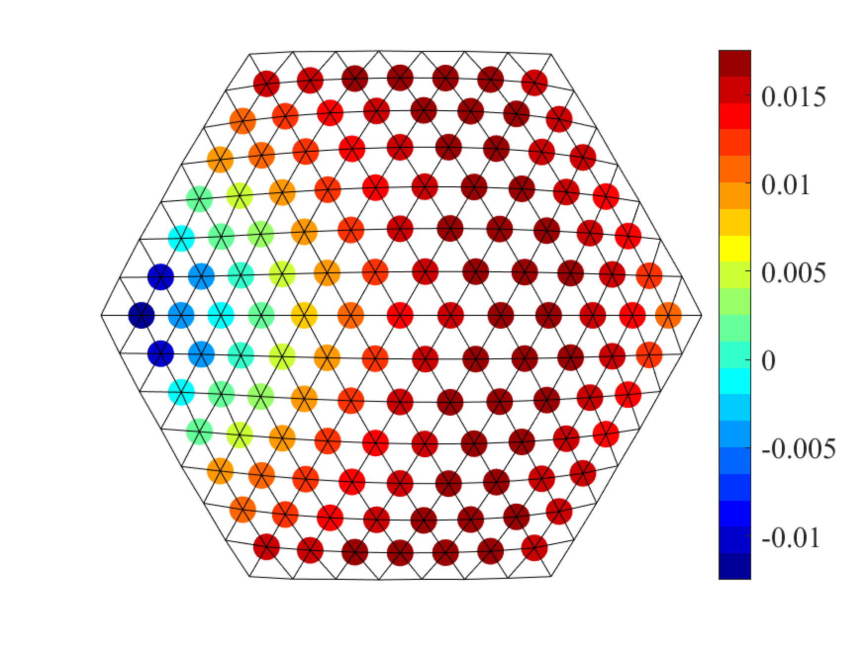
In Example 3, we are to design a surface with varied target Gaussian curvatures taking positive values at some vertices and negative values at the others. The initial geometry of Example 1 is used in this example. We set aiming at equilateral panels (that is, ). The target Gaussian curvatures are assigned by a quadratic curve defined as follows:
| (16) |
where are the -coordinates of the initial embedding, and , , and . The target Gaussian curvature attains the maximum value at , and the minimum value at . The total target Gaussian curvature of the interior vertices is 1.5. The target positions of the boundary vertices are set to the same as in the initial geometry with . Fig. 10 shows the final geometry of the surface.
Example 4: surface with openings
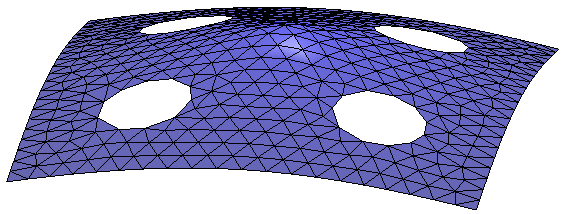
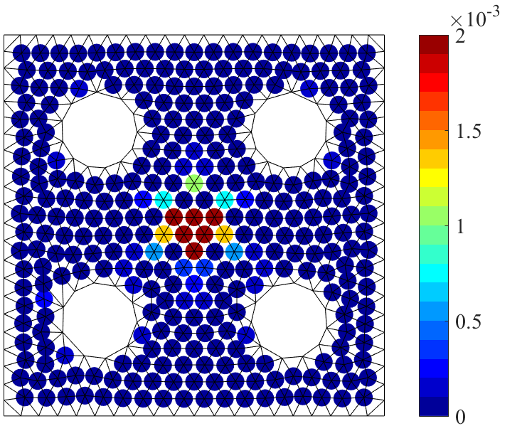
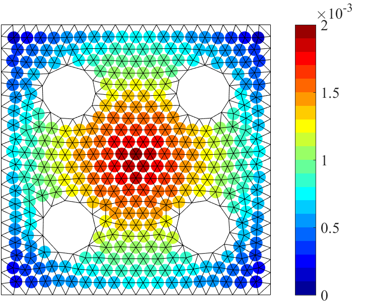
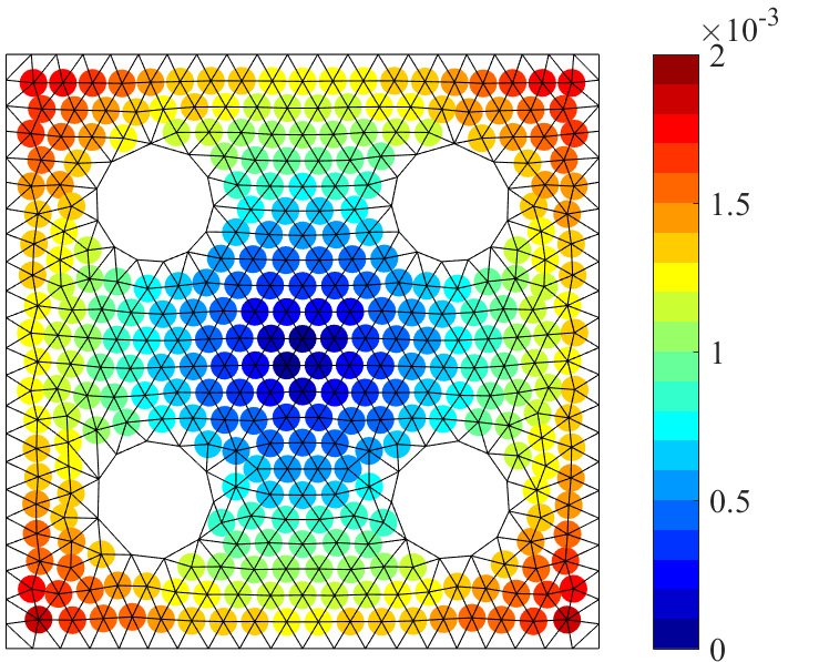
In this example, we consider a surface with a non-trivial topology having four circular openings. The initial geometry, as shown in Fig. 11, is generated by linearly interpolating the centre vertex and the opening. It has almost zero Gaussian curvatures at all vertices except for the centre corn vertex, where the Gaussian curvature concentrates. Its span is 40.0m and its height is 8.0m. This surface is composed of 438 vertices (of which 85 are boundary vertices), 1193 edges, and 752 faces. We set to be all boundary edges including those of four openings, while to be outer boundary vertices excluding those of four openings. This means that the lengths of edges bounding the four openings are preserved but not their positions. We set and . The conformal structure is calculated from the initial geometry by (5) and (4). We have two variations of Example 4. For Example 4a, the target Gaussian curvature is set to 0.002 at the center and zero around the four corners, and linearly interpolated at other internal vertices. On the other hand, for Example 4b, the target Gaussian curvature is set to zero at the center and 0.002 around the four corners, and linearly interpolated at other internal vertices.
The final geometries and the distributions of Gaussian curvatures for these two examples are shown in Fig. 12. We observe that the final geometries are close to their initial geometry while they have the user-defined Gaussian curvatures. The two geometries look quite similar, however, they have different structural properties. The pin-jointed analysis models of the structures with the fixed boundaries show that the structural stiffness, evaluated by external works, of Example 4a is about 1.7 times higher than that of Example 4b. This is mainly due to the lower stiffness (or larger displacements) in the middle part of Example 4b, where the vertices have negative Gaussian curvatures.

Example 5: pointed dome with a side of various constant curvatures
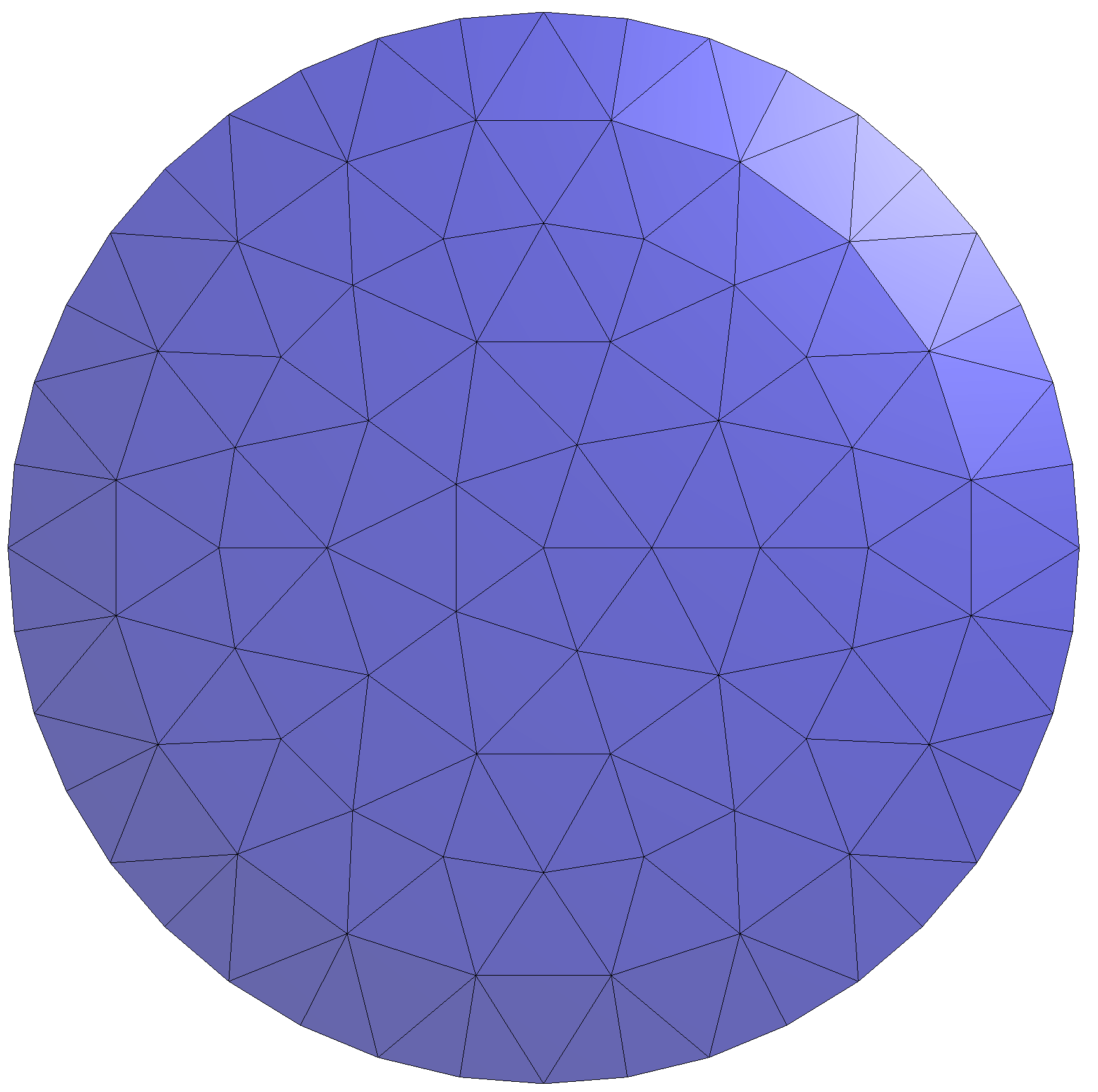
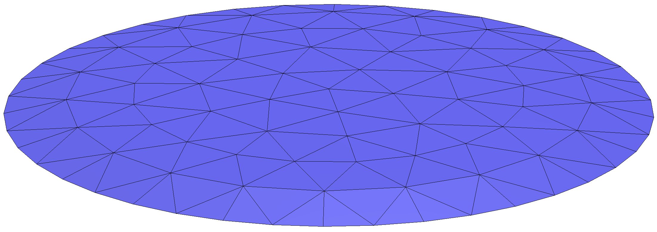
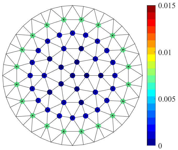
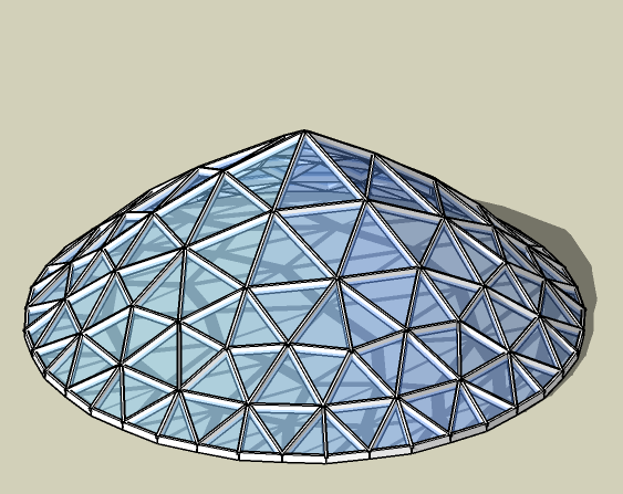
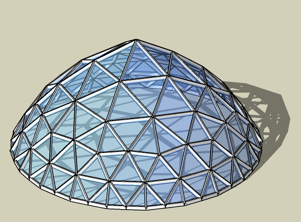
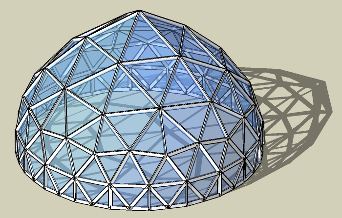
In this example, our algorithm is used to find the design of domes, where the apex has a fixed curvature of and the side has the constant target curvature . The initial design is given Figure 13, which is almost flat with 96 vertices and 150 faces. We set , , and . Fig. 14 shows the final design with three different target curvatures , which give quite different silhouette and impression. The target curvature can be chosen interactively, providing an easy design tool. Note that if we do not add the convexity constraint and set , the resulting final design is concave, demonstrating the effectiveness of the convexity term (3.2).
Example 6: interactive surface design
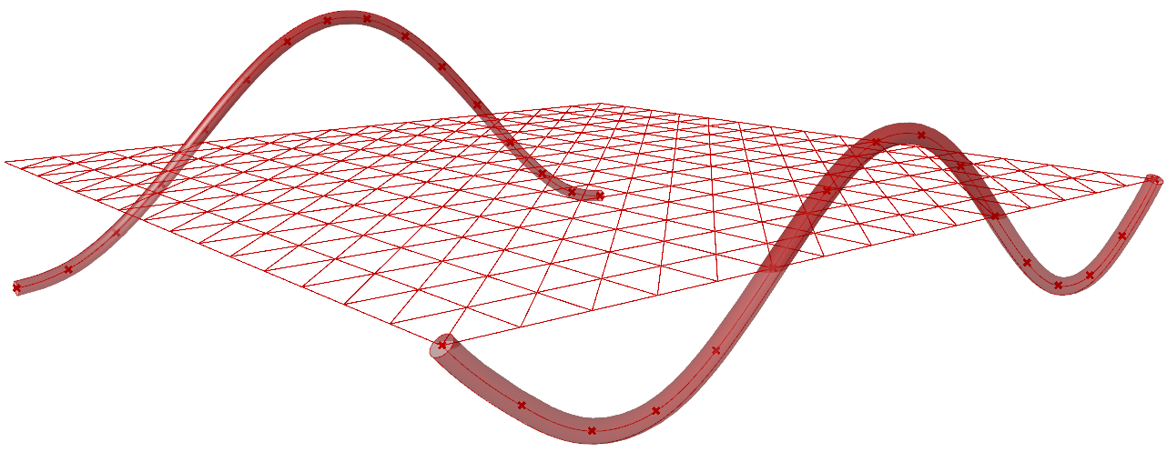
This subsection demonstrates the interactive tool integrated to the widely-used CAD software, Rhinoceros 3D, via its visual programming language Grasshopper. Rhinoceros 3D and Grasshopper are particularly suitable for parametric design of architecture and fabrication [30]. Our design tool comprises the following four parts as shown in Fig. 15:
-
•
Part 1: Initial Mesh Generation
The initial geometry lying on the -plane is generated according to the user specified spans in - and -directions for a square plan, and the divisions in each direction. -
•
Part 2: Boundary Curve Setting
Boundary curves are defined. -
•
Part 3: Metric & Embedding Optimisation
The metric optimization is performed with specified parameters. Two common conformal structure presets are defined; “Inversive” to obtain panel shapes close to the initial one or “Combinatorial” to obtain panel shapes close to equilateral triangles. The embedding optimisation is subsequently performed with the assigned weights. -
•
Part 4: Final Geometry Display
The final geometry is displayed with simple rendering in the Rhinoceros 3D.
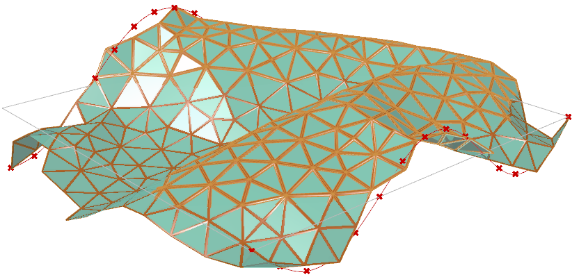
As an illustrative example, we create a CGC surface with a square plan with the spans in both directions set to 30.0m (see the supplementary video). The design region is uniformly divided into 15 sections in - and -directions. There are in total 256 vertices, including 196 inner vertices and 60 boundary vertices, 1410 edges, and 450 triangle panels. One of the boundary curve has the shape of two half cosine waves with the height is 5.0m, and the other has the shape of three half sine waves with the height of 3.0m, as indicated by the thicker curves in Fig. 16 (left figure). The coordinates of the 32 boundary vertices lying on the sine and cosine curves are assigned in Part 2 of the design tool, and the coordinates of the other 24 boundary vertices are automatically determined by the tool. The total target Gaussian curvature for interior vertices is set to (“Interior curvature”), and hence, the target Gaussian curvature of each interior vertex is 2.551. For the conformal structure, we set the constant value by choosing “Combinatorial” in Part 3, aiming at equilateral panels. The final geometry shown in Fig. 16 is obtained by the embedding optimisation with the parameters (“Boundary Weight”), (“Convexity Weight”), (“Regularization Weight”). The distributions of the Gaussian curvatures and the corner angles at the interior vertices for the initial and final meshes are also shown in Fig. 16. It is notable that the specified Gaussian curvatures, the boundary, and the corner angles cannot be achieved at the same time, and trade-off among these factors has be to made and the user can set the priority through the choice of hyper-parameters.

5 Conclusions
In this study, we presented an efficient tool for the design of discrete architectural surfaces having the user-specified Gaussian curvatures and boundary locations while providing control over the shape of the panels through the choice of the conformal class. The proposed method is composed of two successive optimisation procedures: the metric optimisation using a modified Ricci energy and the embedding optimisation to realise the obtained metric. Both are formulated as least-squares problems, and any standard solvers can be used thanks to the closed-form expression of the modified Ricci energy. This formulation and the “change of the variables” in the optimisation problems are the key ideas of the proposed method. Instead of taking vertex coordinates directly as variables, the circle packing radii are chosen first as variables to find a metric. Then, vertex coordinates are used as variables to achieve the obtained metric. These ideas have led to our fast and robust algorithm. In addition, our method offers flexibility in incorporating various design constraints as penalty terms in the least-squares problem. Our implementation is publicly available as open-source and can be easily extended with additional penalty terms and different solvers.
One limitation of the proposed method is that only triangulated mesh can be handled due to the lack of the theory of conformal geometry for general polyhedral meshes or parametric surfaces such as NURBS surfaces. Another limitation is the second step of our optimisation, which is sensitive to the initial geometry. Iterating the first and second steps alternatingly may be required to achieve a plausible balance between the two optimisation steps. Preferably, a more sophisticated method to incorporate the second step into the first one should be developed in the future.
Acknowledgement: This work was supported by JST CREST Grant Number JPMJCR1911. The authors are grateful to Prof. Makoto Ohsaki at Kyoto University for his helpful comments.
References
- [1] Alexander I. Bobenko, Stefan Sechelmann, and Boris Springborn. Discrete Conformal Maps: Boundary Value Problems, Circle Domains, Fuchsian and Schottky Uniformization, pages 1–56. Springer Berlin Heidelberg, Berlin, Heidelberg, 2016.
- [2] Philip L. Bowers and Kenneth Stephenson. Uniformizing dessins and Belyĭ maps via circle packing. Mem. Amer. Math. Soc., 170(805):xii+97, 2004.
- [3] Hongyun Cai, Vincent W Zheng, and Kevin Chang. A comprehensive survey of graph embedding: problems, techniques and applications. IEEE Transactions on Knowledge and Data Engineering, 2018.
- [4] E. Catmull and J. Clark. Recursively generated b-spline surfaces on arbitrary topological meshes. Computer-Aided Design, 10(6):350–355, 1978.
- [5] Albert Chern, Felix Knöppel, Ulrich Pinkall, and Peter Schröder. Shape from metric. ACM Trans. Graph., 37(4):63:1–63:17, August 2018.
- [6] Bennett Chow and Feng Luo. Combinatorial Ricci flows on surfaces. Journal of Differential Geometry, 63(1):97–129, 2003.
- [7] Keenan Crane. Conformal geometry of simplicial surfaces. In Keenan Crane, editor, An Excursion Through Discrete Differential Geometry, Proceedings of Symposia in Applied Mathematics, pages 59–102. American Mathematical Society, 2020.
- [8] Keenan Michael Crane. Conformal Geometry Processing. PhD thesis, California Institute of Technology, 2013. An optional note.
- [9] Stefan Elfwing, Eiji Uchibe, and Kenji Doya. Sigmoid-weighted linear units for neural network function approximation in reinforcement learning. Neural Networks, 107:3–11, 2018. Special issue on deep reinforcement learning.
- [10] P Erdös and M Simonovits. On the chromatic number of geometric graphs. Ars Combin, 9:229–246, 1980.
- [11] Gerardo Gómez-Puerto, Enric Munar, and Marcos Nadal. Preference for curvature: a historical and conceptual framework. Frontiers in Human Neuroscience, 9(JAN2016):1–8, jan 2016.
- [12] Xianfeng Gu, Feng Luo, Jian Sun, and Tianqi Wu. A discrete uniformization theorem for polyhedral surfaces I. Journal of Differential Geometry (JDG), 109(2):223–256, 2018.
- [13] Xianfeng Gu and Shing-Tung Yau. Computational Conformal Geometry, volume 3 of Advanced Lectures in Mathematics. International Press and Higher Education Press, 2007.
- [14] Richards Hamilton. The Ricci flow on surfaces. Contemporary Mathematics, 71:237–262, 1988.
- [15] Jerry L. Hintze and Ray D. Nelson. Violin Plots: A Box Plot-Density Trace Synergism. Statistical computing and graphics, 52(2):181–184, 1998.
- [16] Zils J. Iyengar H, Novak L, Sinn R. Steel framing provided both the strength and lightness needed for the Guggenheim Museum’s complex geometry. Modern Steel Construction, 1998.
- [17] Miao Jin, Xianfeng Gu, Ying He, and Yalin Wang. Conformal Geometry: Computational Algorithms and Engineering Applications. Springer International Publishing, Cham, 2018.
- [18] Miao Jin, Junho Kim, Feng Luo, and Xianfeng Gu. Discrete surface Ricci flow. IEEE Transactions on Visualization and Computer Graphics, 14(5):1030–1043, 2008.
- [19] Quang-Phap Luong and Jong-Ho Nam. Surface modification by superimposing piecewise shape function satisfying hull variation given by arbitrary characteristic curve on surface. Journal of Computational Design and Engineering, 8(4):1125–1140, 07 2021.
- [20] A. Mead. Review of the Development of Multidimensional Scaling Methods. The Statistician, 41(1):27, feb 1992.
- [21] Edwin Gonzalez Meza. The triangle grid, the evolution of layered shells since the beginning of the 19th century. Curved and Layered Structures, 8(1):337–353, jan 2021.
- [22] Andrew Nealen, Takeo Igarashi, Olga Sorkine, and Marc Alexa. Laplacian mesh optimization. In Proceedings of the 4th International Conference on Computer Graphics and Interactive Techniques in Australasia and Southeast Asia, GRAPHITE ’06, page 381–389, New York, NY, USA, 2006. Association for Computing Machinery.
- [23] Helmut Pottmann. Architectural geometry as design knowledge. Architectural Design, 80(4):72–77, 2010.
- [24] Burt Rodin and Dennis Sullivan. The convergence of circle packings to the Riemann mapping. Journal of Differential Geometry, 26(2):349–360, 1987.
- [25] Nicole Ruta, Stefano Mastandrea, Olivier Penacchio, Stefania Lamaddalena, and Giuseppe Bove. A comparison between preference judgments of curvature and sharpness in architectural façades. Architectural Science Review, 62(2):171–181, mar 2019.
- [26] Alexander Schiftner, Mathias Höbinger, Johannes Wallner, and Helmut Pottmann. Packing circles and spheres on surfaces. ACM Transactions on Graphics, 28(5):1–8, 2009.
- [27] Stefan Sechelmann, Thilo Rörig, and Alexander I. Bobenko. Quasiisothermic mesh layout. In Lars Hesselgren, Shrikant Sharma, Johannes Wallner, Niccolo Baldassini, Philippe Bompas, and Jacques Raynaud, editors, Advances in Architectural Geometry 2012, pages 243–258, Vienna, 2013. Springer Vienna.
- [28] Boris Springborn, Peter Schröder, and Ulrich Pinkall. Conformal equivalence of triangle meshes. ACM Trans. Graph., 27(3):1–11, August 2008.
- [29] Jian Sun, Tianqi Wu, Xianfeng Gu, and Feng Luo. Discrete conformal deformation: Algorithm and experiments. SIAM Journal on Imaging Sciences, 8(3):1421–1456, 2015.
- [30] Arturo Tedeschi. Parametric architecture with Grasshopper®: primer. Le Penseur, 2011.
- [31] Xavier Tellier, Cyril Douthe, Laurent Hauswirth, and Olivier Baverel. Linear Weingarten surfaces for conceptual design. Proceedings of the International Symposium on Conceptual Design of Structures, pages 225–232, 2019.
- [32] William P Thurston. Geometry and topology of 3-manifolds. Prinston University, 1980.
- [33] Amir Vaxman, Christian Müller, and Ofir Weber. Conformal mesh deformations with möbius transformations. ACM Trans. Graph., 34(4), July 2015.
- [34] Pauli Virtanen, Ralf Gommers, Travis E. Oliphant, et al. SciPy 1.0: fundamental algorithms for scientific computing in Python. Nature Methods, 17(3):261–272, 2020.
- [35] Yong Liang Yang, Ren Guo, Feng Luo, Shi Min Hu, and Xianfeng Gu. Generalized discrete Ricci flow. Computer Graphics Forum, 28(7):2005–2014, 2009.
- [36] Wei Zeng and Xianfeng David Gu. Ricci Flow for Shape Analysis and Surface Registration. Theories, Algorithms and Applications. Springer, 2013.
- [37] Min Zhang, Ren Guo, Wei Zeng, Feng Luo, Shing Tung Yau, and Xianfeng Gu. The unified discrete surface Ricci flow. Graphical Models, 76(5):321–339, 2014.
- [38] Huanxi Zhao and Guoliang Xu. Triangular surface mesh fairing via Gaussian curvature flow. Journal of Computational and Applied Mathematics, 195(1-2):300–311, 2006.
- [39] Man Zhou, Zhuang Haiyan, and Fang Shujun. Innovations at Beijing Daxing International : the world ’ s biggest airport terminal Daxing has five airside concourses at 60 ° to each. Proceedings of the Institution of Civil Engineers-Civil 522 Engineering. Thomas Telford Ltd, 173(September 2019):113–118, 2020.