Topological magnons for thermal Hall transport in frustrated magnets with bond-dependent interactions
Abstract
Thermal transport in topologically-ordered phases of matter provides valuable insights as it can detect the charge-neutral quasiparticles that would not directly couple to electromagnetic probes. An important example is the edge heat transport of the Majorana fermions in a chiral spin liquid, which leads to a half-quantized thermal Hall conductivity. This signature is precisely what has recently been measured in -RuCl3 under external magnetic fields. The plateau-like behaviour of the half-quantized thermal Hall conductivity as a function of external magnetic field, and the peculiar sign change depending on the magnetic field orientations, have been proposed to be strong evidence for the non-Abelian Kitaev spin liquid. On the other hand, for in-plane magnetic fields, it has been theoretically shown that such a sign structure can also arise from topological magnons in the field-polarized state. In this work, we investigate the full implications of topological magnons as heat carriers on thermal transport measurements. We first prove analytically that for any commensurate order with a finite magnetic unit cell, reversing the field direction leads to a sign change in the magnon thermal Hall conductivity in two-dimensional systems. We corroborate this proof numerically with nontrivial magnetic orders as well as the field-polarized state in Kitaev magnets subjected to an in-plane field. In the case of the tilted magnetic field, in which there exists both finite in-plane and out-of-plane field components, we find that the plateau-like behaviour of the thermal Hall conductivity and the sign change upon the reversal of the in-plane component of the magnetic field arises in the partially-polarized state, as long as the in-plane field contribution to the Zeeman energy is significant. While these results are consistent with the experimental observations, we comment on other aspects that require further investigation in future studies.
pacs:
I Introduction
The search for quantum spin liquid (QSL) statesWitczak-Krempa et al. (2014); Savary and Balents (2016); Zhou et al. (2017); Broholm et al. (2020) with long range entanglement and emergent quasiparticle excitations is of both practical and fundamental interests. One avenue to achieve a QSL state is via magnetic frustrations from bond-dependent interactions, which has motivated the study of materials with strong spin-orbit couplingJackeli and Khaliullin (2009); Chaloupka et al. (2010); Katukuri et al. (2014); Rau et al. (2014); Plumb et al. (2014); Chun et al. (2015); Sears et al. (2020); Rau et al. (2016); Schaffer et al. (2016); Winter et al. (2017); Takagi et al. (2019); Janssen and Vojta (2019). These materials naturally possess bond-dependent interactions and have the potential to realize the Kitaev model on a honeycomb latticeKitaev (2006), and has garnered much intrigue due to it being exactly solvable and having a spin liquid ground stateSandilands et al. (2015); Banerjee et al. (2016, 2017); Baek et al. (2017); Do et al. (2017); Wang et al. (2017); Banerjee et al. (2018). A great leap forward was achieved in the search for the Kitaev spin liquid (KSL) when a half-quantized thermal Hall conductivity was measured in the material -RuCl3 under external magnetic fieldsKasahara et al. (2018a). The half-quantization is a signature of Majorana fermions – the fractionalized excitations of the KSLKitaev (2006); Nasu et al. (2017); Vinkler-Aviv and Rosch (2018); Ye et al. (2018); Balz et al. (2019). Their presence in a real material, once confirmed, would be a major breakthrough in spin liquid physicsJiang et al. ; Hickey and Trebst (2019); Wang et al. (2019); Gordon et al. (2019); Kaib et al. (2019); Chern et al. (2020); Lee et al. (2020); Sørensen et al. ; Chern et al. (a).
The half-quantized thermal Hall conductivity is observed in -RuCl3 not only under tilted fields, but also under completely in-plane fieldsYokoi et al. (2020); Czajka et al. . This is unlike in ordinary metals, in which the electronic Hall effect only occurs when the field has a finite out-of-plane component. Such an anomalous Hall effect in -RuCl3 is postulated to originate from Majorana fermions in the non-Abelian Kitaev spin liquid. For in-plane fields, a sign change in the thermal Hall conductivity was measured when the field was flipped from the to direction, while no appreciable signals were measured when the field was applied along the direction (see Fig. 1). Although this peculiar sign structure of the thermal Hall conductivityUtermohlen and Trivedi is consistent with the non-Abelian KSL scenarioGordon et al. (2019); Gordon and Kee , a recent theoretical studyChern et al. (b) demonstrated that it can also arise from topological magnonsOwerre (2016a, b, 2017); McClarty et al. (2018); Joshi (2018) in the polarized state in Kitaev magnets. In the case of tilted fields in the plane, experiments have measured a similar sign change in the thermal Hall conductivity when the tilting angle from the -axis was switched from degrees to degrees in the suspected spin liquid regimeYokoi et al. (2020). Determining whether these signals are uniquely caused by the non-Abelian QSL state is crucial, thus there is a pressing need to critically examine other possible mechanisms.

In this work, we investigate the possibility of magnons as the heat carriers responsible for the thermal transport observed in experiments. First, we theoretically demonstrate that a sign change in the magnon thermal Hall conductivity follows from reversing the field direction. This generic property holds for any magnetic order with a finite unit cell, and for any field direction, in a bilinear spin model. A concise proof is presented in the main text. In a previous work, the magnon thermal Hall effect in the polarized state was explored for fields parallel to the and directions Chern et al. (b). As an extension to this study, we consider the model and determine the classical phase diagram in the presence of all possible in-plane magnetic field directions. We then show that the general sign change property indeed holds for various magnetic orders and polarized phases appearing in the phase diagram.
Furthermore, we explicitly compute the thermal Hall conductivities for the model under tilted fields. As the field increases, the system does not immediately polarize, but enters a ferromagnetic phase with a dominant in-plane magnetizationJanssen et al. (2017). Therefore, right above the ferromagnetic phase transition, a sign change in the thermal Hall conductivity under the reversal of the in-plane field component can still be observed, as in the case of completely in-plane fields. For the two-dimensional zig-zag ordered stateSears et al. (2015); Johnson et al. (2015) below the critical field, the sign change behaviour can also be observed. We show that certain aspects of magnon heat transport in the model are consistent with experimental results, and highlight others that require further investigations.
The rest of the paper is organized as follows. In Section II, we provide a proof for the sign structure of the magnon thermal Hall conductivity on a bilinear spin Hamiltonian. Section III presents a classical phase diagram with magnetic fields in the plane as well as numerical results of the thermal Hall conductivities. Section IV explores the thermal Hall effect under tilted magnetic fields. We discuss the dependence of the overall sign of the thermal Hall conductivity on the model parameters in Section V. Lastly, Section VI discusses the key findings of this work and provides a future outlook.
II Thermal Hall sign structure
Consider a general bilinear spin Hamiltonian with a Zeeman field,
| (1) |
where is a real symmetric matrix that encodes the interaction between the spins at sites and . Suppose that we have obtained the ground state spin configuration of the classical model in (1). To construct the linear spin wave Hamiltonian Holstein and Primakoff (1940); Jones et al. (1987) for this ground state, the spins are first passively rotated on each site of the lattice such that the -direction of the local coordinate system is parallel to the spin orientation. We define the following rotation matrix
| (2) |
where and are polar angles in the original cubic coordinates, and such that
| (3) |
where, classically, is the spin at measured in the local coordinate system.
The rotated, site-dependent Hamiltonian is then given by
| (4) |
where and . Note that all the elements of are real.
In the rotated basis, we perform a Holstein-Primakoff expansion Holstein and Primakoff (1940),
Keeping only terms that contribute up to quadratic order in the Hamiltonian, we get
Expanding out the first term, we obtain
| (5) |
We assume that the ground state spin configuration is a magnetic order with a finite unit cell of sublattices, so that it has a real space periodicity that allows us to perform the Fourier transform, which yields
| (6) |
where and label the sublattices of an interacting pair of spins, which belong to the magnetic unit cells and respectively. Factors of 1/2 are inserted to avoid double counting. Then, we can write the spin wave Hamiltonian in the form of
| (7) |
where the spinor , and is a matrix of the form
| (8) |
with and being dimensional matrices. Using this linear spin wave formalism, we present the following theorem:
Theorem 1.
When the direction of the external magnetic field in (1) is reversed, there is a sign change in the magnon thermal Hall conductivity for any magnetic order with a finite unit cell.
Proof.
For the Hamiltonian (1), when the Zeeman field transforms as , the spins in the ground state undergo a transformation of
or equivalently , such that the ground state energy remains unchanged. In other words, if is the ground state spin configuration under the field , then is the ground state spin configuration under the field .
The rotated spin Hamiltonians under the fields and are given by
Therefore, when the field direction is reversed, the only components of the rotated Hamiltonian relevant to linear spin wave theory that pick up a sign change are and . For the rotated field, the Zeeman term contribution to the linear spin wave theory remains unchanged. From equations (6) and (8), we find that . If the system is two-dimensional, we can show that changes sign, and the details of the proof can be found in a previous workChern et al. (b). ∎
Theorem 1 holds for any magnetic order with a finite unit cell on the underlying Bravais lattice, and for any field direction. It is independent of the details of the spin interactions as long as it is bilinear. In particular, the theorem holds for any order of nearest neighbour interaction, including the first- and third-nearest neighbour Heisenberg interactions, and ; we only require the ground state to exhibit a translational symmetry (defined by the magnetic unit cell), such that we are able to define the linear spin wave Hamiltonian in the momentum space (6). A situation in which this theorem breaks down is a magnetic order that is incommensurate with the lattice and thus devoid of translational symmetry. In the following sections, we will be exploring this general sign change property in the model.
III Classical phase diagram with the magnetic field in the -plane and thermal Hall conductivity
We consider the model under a magnetic field as a model for -RuCl3, which is given by where
| (11) |
First, we chose a model with , , and , and we numerically explored the classical ground states using simulated annealingJanssen et al. (2016); Chern et al. (2020) with in-plane magnetic fields , with and . These computations resulted in a rich phase diagram shown in Fig. 2a, which notably includes non-trivial intermediate phases between zig-zag orders and the polarized state – the largest of which contains 10 sites per magnetic unit cell. Neutron scattering experiments have been performed to obtain the phase diagram for a field applied parallel to the axis, but not the axisBalz et al. . Thus, a potential application of this in-plane phase diagram is to serve as an initial predictor for future experiments.

There are three distinct configurations for each of the ZZ, 6-siteLampen-Kelley et al. , and 10-site orders, examples of which are shown in the Supplemental MaterialsSM . Note that when the field is along the -directionChern et al. (2020), the three configurations of each order are degenerate and related by the symmetry of the system. For in-plane fields, the symmetry is broken, such that the three configurations of each order in general differ in energy. However, when the in-plane field is applied along high-symmetry directions that are equivalent to the or direction, two configurations of the same order may be degenerate. For example, 6a and 6b are degenerate under magnetic fields along the and directions, see Fig. 2b.
To calculate due to magnons, we first obtained the linear spin wave dispersion by diagonalizing (8) using a Bogoliubov transformationBogoljubov (1947). We then computed the Berry curvature using the Bogoliubov transformation matrices . is given byMatsumoto and Murakami (2011); Matsumoto et al. (2014); Murakami and Okamoto (2017)
| (12) |
where FBZ is the crystal first Brillouin zone, , and is the Bose-Einstein distribution. To ensure the convergence of at system size , we also checked that the Chern number
| (13) |
where is the total area of the system, converged to an integer for each magnon band. Topological magnons are indicated by finite Chern numbers. For example, when the field was applied along the direction, we found that the two magnon bands of the polarized state carried the Chern numbers , while the six magnon bands of the 6-site order carried the Chern numbers .
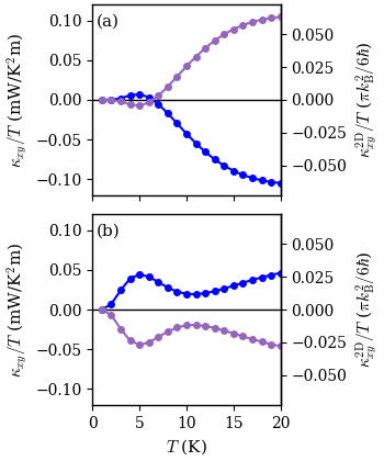
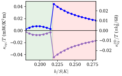
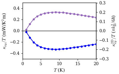
We set the spin magnitude to be in the linear spin wave theory and calculated the magnon thermal Hall conductivity. We assumed the strength of the Kitaev interaction to be Kim and Kee (2016); Kasahara et al. (2018b), and set the interlayer distance to be for -RuCl3Johnson et al. (2015); Kasahara et al. (2018b, a); Yokoi et al. (2020). We present the thermal Hall conductivities for the 6-site order and the polarized state as a function of temperature in Figs. 3(a)-(b), and as a function of field strength across the phase boundary in Fig. 4, when the field was applied along the direction. The field strengths in each plot were chosen to be close to the critical field separating the two magnetic orders. We make some observations from these results. First, large unit cell orders like the 6-site order can give rise to a finite thermal Hall effect. Additionally, the thermal Hall conductivity of the polarized state is much larger than that of the 6-site order for the parameterization we chose; a similar pattern can be seen in the experimental results. Furthermore, the thermal Hall conductivities of both orders under magnetic fields along the and direction are equal in magnitude and opposite in sign, as predicted by Theorem 1.
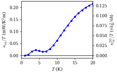
We remark that the thermal Hall conductivity is not always zero when the external field is applied along the direction, as is for the polarized state. The lack of a signal for the polarized state is a special case that arises from a rotational symmetry about the axis in both the Hamiltonian and the ground state spin configuration. Such a symmetry can be broken by other magnetic orders, for example the 6-site order, which shows a finite thermal Hall conductivity when the field is applied along the direction (see Fig. 5).
IV Thermal Hall conductivity in the presence of tilted fields
As explored in Sec. II, there is a well-established relation between the reversal of the field direction and the sign change of the magnon . However, for a tilted field, the effect of reversing only the in-plane component , while fixing the out-of-plane component , on the magnon is unclear. This is because the ground state spin configurations of and have no direct relation in general, unlike those of and which are related by flipping of the spins.
In the experimentYokoi et al. (2020), the tilted field was applied in the -plane. The tilting angle is defined to be the angle between the field and the -axis. A sign change in was experimentally observed in the proposed spin liquid regime when was changed from and . In this section, we propose a scenario where such a sign change can happen in the magnon . The underlying magnetically ordered ground state is the partially-polarized ferromagnet (PPF), which will be described below.
For a tilted field, assuming classical spins, the system enters the ferromagnetic state at sufficiently high fields, but is never completely polarized at finite fields. This effect originates from the competition between the interaction and the external fieldJanssen et al. (2017). We refer to such a ferromagnetic state as the PPF. As in the experiment, we applied fields in the -plane with tilting angles and measured from the -axis. Using the parametrization , we find that right after the system enters the PPF, the magnetization is largely in-plane, as shown in Tables 1 and 2. As the field strength increases, the in-plane (out-of-plane) component of the magnetization gradually decreases (increases).
| 0.10 | 0.996103 | 0 | 0.088193 |
| 0.12 | 0.994717 | 0 | 0.102656 |
| 0.14 | 0.993218 | 0 | 0.116265 |
| 0.16 | 0.991633 | 0 | 0.129088 |
| 0.18 | 0.989983 | 0 | 0.141185 |
| 0.05 | 0.998427 | 0 | 0.056059 |
| 0.07 | 0.997302 | 0 | 0.073410 |
| 0.09 | 0.996064 | 0 | 0.088640 |
| 0.11 | 0.994774 | 0 | 0.102106 |
| 0.13 | 0.993470 | 0 | 0.114090 |
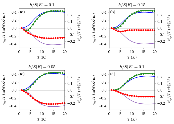
We plot the thermal Hall conductivities as a function of temperature for isotropic (Figs. 6a and 6b) and anisotropic (Figs. 6c and 6d) -tensors. The -tensor effectively modifies the field as , where we chose and for the isotropic and anisotropic cases respectivelyYadav et al. (2016); Winter et al. (2018); Chaloupka and Khaliullin (2016). The fields in 6a and 6c were chosen to be near the respective critical fields, such that the magnetizations of the PPFs were almost in-plane, i.e. . We then expect the thermal Hall signals of these PPFs (e.g. curves with dots in Fig. 6c) to be similar to those of the ferromagnetic states with completely in-plane magnetizations, i.e. (e.g. curves without dots in Fig. 6c). As we increase the field, the out-of-plane magnetization of the PPF becomes more significant, resulting in a larger deviation in from the case of a completely in-plane magnetization. Such a deviation is more prevalent in the case of isotropic -tensor. This result is expected, since a heavier weight is placed on the in-plane component of the field in the anisotropic case, which would result in a slower polarization as seen in Table 2. Therefore, it is not guaranteed that the magnon thermal Hall conductivity will have exactly the same magnitude and opposite sign by changing from to . However, Fig. 6c shows a regime in which we can obtain an approximate version of this behaviour.
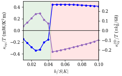
In Fig. 7, we plot the thermal Hall conductivities for a zig-zag ordered state and a PPF state near the critical field. Some of these results are consistent with the thermal Hall signals that have been experimentally measuredYokoi et al. (2020). We observe that the maximum PPF signal is larger than that of the zig-zag. It can be shown that this behaviour can be further optimized by tuning the system parameters such that the zig-zag signal is oppressed, while the PPF signal is preserved. Additionally, the PPF signal decays more rapidly as the field strength increases for the field than the field, which is also observed. Notably, the signal as well as the field also exhibits a plateau-like behaviour in the PPF region (the proposed spin liquid region in Ref. Yokoi et al., 2020). However, there are also a few aspects of our result that still require further investigation. In particular, we observe a sign change in the zig-zag region near the critical field, which is expected due to the same argument applied for the PPF state, whereas no sign change was observed in the experiment. A possible explanation for this discrepancy is that we did not consider any 3-dimensional inter-layer ordering in our model. A recent neutron scattering experimentBalz et al. revealed that there is a stacking of the layers in the zig-zag order, therefore if magnons are the predominant heat carrier, then the lack of a sign change most likely arises from this 3D order, which remains to be explored in a future work.
V Overall sign of
We have proven in Sec. II that the sign change of upon reversing the field direction is universal (Theorem 1). However, the overall sign of for a given field direction depends on the choice of model parameters. For example, if we choose – a different yet realistic parameterization of -RuCl3 – the overall sign of in the polarized state is opposite to those obtained from our earlier calculations. As shown in Fig. 8, is negative (positive) when the field is applied along the () direction, which is consistent with the overall sign observed in Ref. Yokoi et al., 2020. This is unlike the sign of due to Majorana fermions in the non-Abelian Kitaev spin liquid, which is solely determined by the field directionKitaev (2006). As we tune the interaction parameters, apart from a possible change of the overall sign of , all other phenomenology remains the same. We have demonstrated that while the relative sign of is universal, its overall sign is parameter-dependent, and our analyses thus far are applicable to the experiments.
VI Discussion
In the present work, we investigated the influence of topological magnons on thermal Hall transport in quantum magnets. We first presented an analytical proof showing that for an arbitrary 2D commensurate magnetic order as well as the field-polarized state, due to magnons changes sign whenever the magnetic field is reversed, irrespective of the initial orientation of the field. Partly motivated by a recent experiment on -RuCl3Yokoi et al. (2020), we investigated this effect numerically in a microscopic model for Kitaev magnets. For example, we demonstrated that the magnon of the 6-site magnetic order and field-polarized state changes the sign when the field orientation is changed from to directions. We emphasize that even though this theorem guarantees the sign change, it does not necessarily lead to a finite magnitude. In the microscopic model for Kitaev magnets, we showed that the finite magnitude of arises due to the topological nature of the magnons, or the Berry curvature of the magnon bands. When the field is applied along -direction, is generally non-zero for commensurate ordered states, in contrast to the vanishing in the case of the field-polarized state reported earlierChern et al. (b) (as also observed in the experimentYokoi et al. (2020)).
In the experiment on -RuCl3, was also measured under tilted magnetic fields and it was found that the sign change of occurs upon reversing only the in-plane field component, while preserving the out-of-plane field component Yokoi et al. (2020). In this case, our theorem in Section II does not directly apply. On the other hand, we demonstrated that, as long as the in-plane field contribution to the Zeeman energy dominates, the sign change of still occurs. In addition, the plateau-like behaviour (or very slow change) of in the partially-polarized state as a function of magnetic field strength also arises in this situation. We note, however, that the value of is not quantized, and it varies as a function of temperature.
One notable difference between our results and the published data on -RuCl3 lies in the ZZ ordered region of the tilted magnetic field experiments. The sign reversal of upon flipping of the magnetic field (our theorem in Section II) applies for any commensurate order. Then, for a 2D ZZ order, there must also be a sign change in , assuming that the in-plane contribution to the Zeeman energy dominates. In the experimental data, however, this sign change was absent in the ZZ region. A possible explanation of this difference lies in the 3D nature of the ZZ order. A neutron scattering (NS) experimentBalz et al. confirmed that below the critical field, the ZZ ordering was 3D, while the polarized regime was 2D with a small interlayer correlation length. These NS measurements imply that our results are applicable for the polarized region, whereas our calculations for in the 2D ZZ ordered state may not directly apply. In order to resolve this issue, one may have to take into account possibly complex interlayer couplings to model the 3D ZZ order. The importance of the 3D nature of the ZZ order thus remains to be investigated in future studies.
While there is always a relative sign between the magnon thermal Hall conductivities under opposite field directions according to Theorem 1, the overall sign of in each of these field directions really depends on the choice of model parameters. We have shown in Sec. V an example parameter set that yields overall signs of consistent with those observed in Yokoi et alYokoi et al. (2020); sig . Moreover, under in-plane fields along the directions, our calculated due to magnons in the polarized state shows a monotonic increase in magnitude as a function of temperature in the low temperature regime, and vanishes in the zero temperature limit. These features agree with the recent experimental data in Ref. Czajka et al., . Thus, the presence of a half-quantized thermal Hall conductivity at very low temperatures remains as the ultimate test for the non-Abelian Kitaev spin liquid.
Acknowledgements.
We thank Takasada Shibauchi for helpful discussions. We acknowledge support from the Natural Sciences and Engineering Research Council of Canada (NSERC). E.Z.Z. was further supported by the NSERC Canada Graduate Scholarships - Doctoral (CGS-D), and L.E.C by the Ontario Graduate Scholarship. Y.B.K. was further supported by the Killam Research Fellowship from the Canada Council for the Arts and the Center for Quantum Materials at the University of Toronto. Most of the computations were performed on the Cedar and Niagara clusters, which are hosted by WestGrid and SciNet in partnership with Compute Canada.References
- Witczak-Krempa et al. (2014) W. Witczak-Krempa, G. Chen, Y. B. Kim, and L. Balents, Annual Review of Condensed Matter Physics 5, 57 (2014).
- Savary and Balents (2016) L. Savary and L. Balents, Reports on Progress in Physics 80, 016502 (2016).
- Zhou et al. (2017) Y. Zhou, K. Kanoda, and T.-K. Ng, Rev. Mod. Phys. 89, 025003 (2017).
- Broholm et al. (2020) C. Broholm, R. J. Cava, S. A. Kivelson, D. G. Nocera, M. R. Norman, and T. Senthil, Science 367 (2020), 10.1126/science.aay0668.
- Jackeli and Khaliullin (2009) G. Jackeli and G. Khaliullin, Phys. Rev. Lett. 102, 017205 (2009).
- Chaloupka et al. (2010) J. Chaloupka, G. Jackeli, and G. Khaliullin, Phys. Rev. Lett. 105, 027204 (2010).
- Katukuri et al. (2014) V. M. Katukuri, S. Nishimoto, V. Yushankhai, A. Stoyanova, H. Kandpal, S. Choi, R. Coldea, I. Rousochatzakis, L. Hozoi, and J. van den Brink, New Journal of Physics 16, 013056 (2014).
- Rau et al. (2014) J. G. Rau, E. K.-H. Lee, and H.-Y. Kee, Phys. Rev. Lett. 112, 077204 (2014).
- Plumb et al. (2014) K. W. Plumb, J. P. Clancy, L. J. Sandilands, V. V. Shankar, Y. F. Hu, K. S. Burch, H.-Y. Kee, and Y.-J. Kim, Phys. Rev. B 90, 041112 (2014).
- Chun et al. (2015) S. H. Chun, J.-W. Kim, J. Kim, H. Zheng, C. C. Stoumpos, C. D. Malliakas, J. F. Mitchell, K. Mehlawat, Y. Singh, Y. Choi, T. Gog, A. Al-Zein, M. M. Sala, M. Krisch, J. Chaloupka, G. Jackeli, G. Khaliullin, and B. J. Kim, Nature Physics 11, 462 (2015).
- Sears et al. (2020) J. A. Sears, L. E. Chern, S. Kim, P. J. Bereciartua, S. Francoual, Y. B. Kim, and Y.-J. Kim, Nature Physics 16, 837 (2020).
- Rau et al. (2016) J. G. Rau, E. K.-H. Lee, and H.-Y. Kee, Annual Review of Condensed Matter Physics 7, 195 (2016).
- Schaffer et al. (2016) R. Schaffer, E. K.-H. Lee, B.-J. Yang, and Y. B. Kim, Reports on Progress in Physics 79, 094504 (2016).
- Winter et al. (2017) S. M. Winter, A. A. Tsirlin, M. Daghofer, J. van den Brink, Y. Singh, P. Gegenwart, and R. Valentí, Journal of Physics: Condensed Matter 29, 493002 (2017).
- Takagi et al. (2019) H. Takagi, T. Takayama, G. Jackeli, G. Khaliullin, and S. E. Nagler, Nature Review Physics 1, 264 (2019).
- Janssen and Vojta (2019) L. Janssen and M. Vojta, Journal of Physics: Condensed Matter 31, 423002 (2019).
- Kitaev (2006) A. Kitaev, Annals of Physics 321, 2 (2006).
- Sandilands et al. (2015) L. J. Sandilands, Y. Tian, K. W. Plumb, Y.-J. Kim, and K. S. Burch, Phys. Rev. Lett. 114, 147201 (2015).
- Banerjee et al. (2016) A. Banerjee, C. A. Bridges, J.-Q. Yan, A. A. Aczel, L. Li, M. B. Stone, G. E. Granroth, M. D. Lumsden, Y. Yiu, J. Knolle, S. Bhattacharjee, D. L. Kovrizhin, R. Moessner, D. A. Tennant, D. G. Mandrus, and S. E. Nagler, Nature Materials 15, 133 (2016).
- Banerjee et al. (2017) A. Banerjee, J. Yan, J. Knolle, C. A. Bridges, M. B. Stone, M. D. Lumsden, D. G. Mandrus, D. A. Tennant, R. Moessner, and S. E. Nagler, Science 356, 1055 (2017).
- Baek et al. (2017) S.-H. Baek, S.-H. Do, K.-Y. Choi, Y. S. Kwon, A. U. B. Wolter, S. Nishimoto, J. van den Brink, and B. Büchner, Phys. Rev. Lett. 119, 037201 (2017).
- Do et al. (2017) S.-H. Do, S.-Y. Park, J. Yoshitake, J. Nasu, Y. Motome, Y. Kwon, D. T. Adroja, D. J. Voneshen, K. Kim, T.-H. Jang, J.-H. Park, K.-Y. Choi, and S. Ji, Nature Physics 13, 1079 (2017).
- Wang et al. (2017) Z. Wang, S. Reschke, D. Hüvonen, S.-H. Do, K.-Y. Choi, M. Gensch, U. Nagel, T. Rõõm, and A. Loidl, Phys. Rev. Lett. 119, 227202 (2017).
- Banerjee et al. (2018) A. Banerjee, P. Lampen-Kelley, J. Knolle, C. Balz, A. A. Aczel, B. Winn, Y. Liu, D. Pajerowski, J. Yan, C. A. Bridges, A. T. Savici, B. C. Chakoumakos, M. D. Lumsden, D. A. Tennant, R. Moessner, D. G. Mandrus, and S. E. Nagler, npj Quantum Materials 3, 8 (2018).
- Kasahara et al. (2018a) Y. Kasahara, T. Ohnishi, Y. Mizukami, O. Tanaka, S. Ma, K. Sugii, N. Kurita, H. Tanaka, J. Nasu, Y. Motome, T. Shibauchi, and Y. Matsuda, Nature 559, 227 (2018a).
- Nasu et al. (2017) J. Nasu, J. Yoshitake, and Y. Motome, Phys. Rev. Lett. 119, 127204 (2017).
- Vinkler-Aviv and Rosch (2018) Y. Vinkler-Aviv and A. Rosch, Phys. Rev. X 8, 031032 (2018).
- Ye et al. (2018) M. Ye, G. B. Halász, L. Savary, and L. Balents, Phys. Rev. Lett. 121, 147201 (2018).
- Balz et al. (2019) C. Balz, P. Lampen-Kelley, A. Banerjee, J. Yan, Z. Lu, X. Hu, S. M. Yadav, Y. Takano, Y. Liu, D. A. Tennant, M. D. Lumsden, D. Mandrus, and S. E. Nagler, Phys. Rev. B 100, 060405 (2019).
- (30) H.-C. Jiang, C.-Y. Wang, B. Huang, and Y.-M. Lu, arXiv:1809.08247 .
- Hickey and Trebst (2019) C. Hickey and S. Trebst, Nature Communications 10, 530 (2019).
- Wang et al. (2019) J. Wang, B. Normand, and Z.-X. Liu, Phys. Rev. Lett. 123, 197201 (2019).
- Gordon et al. (2019) J. S. Gordon, A. Catuneanu, E. S. Sørensen, and H.-Y. Kee, Nature Communications 10, 2470 (2019).
- Kaib et al. (2019) D. A. S. Kaib, S. M. Winter, and R. Valentí, Phys. Rev. B 100, 144445 (2019).
- Chern et al. (2020) L. E. Chern, R. Kaneko, H.-Y. Lee, and Y. B. Kim, Phys. Rev. Research 2, 013014 (2020).
- Lee et al. (2020) H.-Y. Lee, R. Kaneko, L. E. Chern, T. Okubo, Y. Yamaji, N. Kawashima, and Y. B. Kim, Nature Communications 11, 1639 (2020).
- (37) E. S. Sørensen, A. Catuneanu, J. S. Gordon, and H.-Y. Kee, arXiv:2007.07259 .
- Chern et al. (a) L. E. Chern, F. L. Buessen, and Y. B. Kim, (a), arXiv:2009.03332 .
- Yokoi et al. (2020) T. Yokoi, S. Ma, Y. Kasahara, S. Kasahara, T. Shibauchi, N. Kurita, H. Tanaka, J. Nasu, Y. Motome, C. Hickey, S. Trebst, and Y. Matsuda, (2020), arXiv:2001.01899 .
- (40) P. Czajka, T. Gao, M. Hirschberger, P. Lampen-Kelley, A. Banerjee, J. Yan, D. G. Mandrus, S. E. Nagler, and N. P. Ong, arXiv:2102.11410 .
- (41) F. G. Utermohlen and N. Trivedi, arXiv:2012.11604 .
- (42) J. S. Gordon and H.-Y. Kee, arXiv:2004.13723 .
- Chern et al. (b) L. E. Chern, E. Z. Zhang, and Y. B. Kim, (b), arXiv:2008.12788 .
- Owerre (2016a) S. A. Owerre, Journal of Applied Physics 120, 043903 (2016a).
- Owerre (2016b) S. A. Owerre, Phys. Rev. B 94, 094405 (2016b).
- Owerre (2017) S. A. Owerre, Journal of Physics: Condensed Matter 29, 385801 (2017).
- McClarty et al. (2018) P. A. McClarty, X.-Y. Dong, M. Gohlke, J. G. Rau, F. Pollmann, R. Moessner, and K. Penc, Phys. Rev. B 98, 060404 (2018).
- Joshi (2018) D. G. Joshi, Phys. Rev. B 98, 060405 (2018).
- Janssen et al. (2017) L. Janssen, E. C. Andrade, and M. Vojta, Phys. Rev. B 96, 064430 (2017).
- Sears et al. (2015) J. A. Sears, M. Songvilay, K. W. Plumb, J. P. Clancy, Y. Qiu, Y. Zhao, D. Parshall, and Y.-J. Kim, Phys. Rev. B 91, 144420 (2015).
- Johnson et al. (2015) R. D. Johnson, S. C. Williams, A. A. Haghighirad, J. Singleton, V. Zapf, P. Manuel, I. I. Mazin, Y. Li, H. O. Jeschke, R. Valentí, and R. Coldea, Phys. Rev. B 92, 235119 (2015).
- Holstein and Primakoff (1940) T. Holstein and H. Primakoff, Phys. Rev. 58, 1098 (1940).
- Jones et al. (1987) D. H. Jones, Q. A. Pankhurst, and C. E. Johnson, Journal of Physics C: Solid State Physics 20, 5149 (1987).
- Janssen et al. (2016) L. Janssen, E. C. Andrade, and M. Vojta, Phys. Rev. Lett. 117, 277202 (2016).
- (55) C. Balz, L. Janssen, P. Lampen-Kelley, A. Banerjee, Y. Liu, J. Yan, D. Mandrus, M. Vojta, and S. E. Nagler, arXiv:2012.15258 .
- (56) P. Lampen-Kelley, L. Janssen, E. C. Andrade, S. Rachel, J.-Q. Yan, C. Balz, D. G. Mandrus, S. E. Nagler, and M. Vojta, arXiv:1807.06192 .
- (57) See Supplemental Material at [URL will be inserted by publisher] for details of the magnetic orders.
- Bogoljubov (1947) N. N. Bogoljubov, J. Phys. USSR 11, 23 (1947).
- Matsumoto and Murakami (2011) R. Matsumoto and S. Murakami, Phys. Rev. Lett. 106, 197202 (2011).
- Matsumoto et al. (2014) R. Matsumoto, R. Shindou, and S. Murakami, Phys. Rev. B 89, 054420 (2014).
- Murakami and Okamoto (2017) S. Murakami and A. Okamoto, Journal of the Physical Society of Japan 86, 011010 (2017).
- Kim and Kee (2016) H.-S. Kim and H.-Y. Kee, Phys. Rev. B 93, 155143 (2016).
- Kasahara et al. (2018b) Y. Kasahara, K. Sugii, T. Ohnishi, M. Shimozawa, M. Yamashita, N. Kurita, H. Tanaka, J. Nasu, Y. Motome, T. Shibauchi, and Y. Matsuda, Phys. Rev. Lett. 120, 217205 (2018b).
- Yadav et al. (2016) R. Yadav, N. A. Bogdanov, V. M. Katukuri, S. Nishimoto, J. Van Den Brink, and L. Hozoi, Scientific Reports 6, 1 (2016).
- Winter et al. (2018) S. M. Winter, K. Riedl, D. Kaib, R. Coldea, and R. Valentí, Physical Review Letters 120, 77203 (2018).
- Chaloupka and Khaliullin (2016) J. Chaloupka and G. Khaliullin, Phys. Rev. B 94, 064435 (2016).
- (67) In our earlier work, Ref. [43], we used model parameters such that the overall sign of would be consistent with the sign convention used in Ref. [25]. In Sec. V of this work, the overall sign of resulting from the parametrization would be consistent with the updated sign convention in Ref. [39].