Visibility of Black Hole Shadows in Low-luminosity AGN
Abstract
Accreting black holes tend to display a characteristic dark central region called the black-hole shadow, which depends only on spacetime/observer geometry and which conveys information about the black hole’s mass and spin. Conversely, the observed central brightness depression, or image shadow, additionally depends on the morphology of the emission region. In this paper, we investigate the astrophysical requirements for observing a meaningful black-hole shadow in GRMHD-based models of accreting black holes. In particular, we identify two processes by which the image shadow can differ from the black-hole shadow: evacuation of the innermost region of the accretion flow, which can render the image shadow larger than the black-hole shadow, and obscuration of the black-hole shadow by optically thick regions of the accretion flow, which can render the image shadow smaller than the black-hole shadow, or eliminate it altogether. We investigate in which models the image shadows of our models match their corresponding black-hole shadows, and in which models the two deviate from each other. We find that, given a compact and optically thin emission region, our models allow for measurement of the black-hole shadow size to an accuracy of 5%. We show that these conditions are generally met for all MAD simulations we considered, as well as some of the SANE simulations.
keywords:
black-hole physics – radiative transfer – accretion, accretion discs1 Introduction
The Event Horizon Telescope (EHT) is an international network of telescopes that is capable of resolving the accretion flows (jets and discs) around the central supermassive black holes of certain low-luminosity active galactic nuclei (LLAGN) (Event Horizon Telescope Collaboration, 2019a, ). Primary EHT targets are the LLAGN hosted by the galaxies M87 and the Milky Way, named M87* and Sagittarius A* (Sgr A*), respectively. Such sources are thought to contain advection-dominated accretion flows (ADAF’s) that produce astrophysical jets (Yuan et al., 2002; Yuan and Narayan, 2014). M87* has been shown to display a central brightness depression (CBD), which theoretical calculations had predicted to be a key feature of accreting (or back-lit) black holes (see, e.g., Luminet, 1979, Falcke et al., 2000, and Noble et al., 2007). Falcke et al., (2000) showed that, given an optically thin, spherical accretion flow, the observed shape of the CBD - which we shall call the image shadow (IS) - conforms to the projection of the unstable-photon region, which those authors called the black-hole shadow (BHS). The shape of the BHS depends only on the mass and spin of the black hole (Broderick, 2006; Johannsen and Psaltis, 2010; Younsi et al., 2016), and therefore, according to the no-hair theorem, it characterises an electrically neutral black hole completely (Heusler,, 1996). In practice, measuring the BHS to the required precision for determining the black-hole spin is extremely technically challenging, due to the intrinsic spatio-temporal variability of the source (Johannsen and Psaltis, 2010; Broderick et al., 2014). The mass, however, which is directly proportional to the radius of the BHS, is a more robust observable. The mass of an LLAGN such as Sgr A* may also be experimentally determined from the orbital elements of stars in its immediate environment, such as the star S2 (Boehle et al.,, 2016), and from infrared interferometry experiments by the GRAVITY collaboration (Gravity Collaboration,, 2020). In this way, combined measurements enable a strong-field test of whether the observed objects are black holes as described by Einstein’s general theory of relativity (GR) as opposed to other objects described by an alternative theory (see, e.g., Broderick et al., 2014; Psaltis et al., 2015b ; Vincent et al., 2016; Hertog and Hartle, 2017; Mizuno et al., 2018; Olivares et al., 2018; Hertog et al., 2019).
Unlike the BHS, the IS of an accreting black hole is determined both by the strongly curved spacetime in the vicinity of the black hole (parametrized by the black hole’s mass and spin) and by the properties of the radiating plasma, such as the geometrical shape of the accretion disc and the radiating electrons’ energy-distribution function (see, e.g., Broderick and Loeb, 2006; Noble et al., 2007; Mościbrodzka et al., 2009). Although it has been demonstrated that, except in the case of an optically thick accretion disc that obscures the black hole, one expects to observe a significant CBD in GRMHD models of accreting black holes (Mościbrodzka et al., 2014; Chan et al., 2015), it is still true that the IS does not always match the BHS. Gralla et al., (2019) showed that certain analytical models may produce circular IS’s that do not match their associated BHS’s. Such mismatches may also occur in physically motivated models. For example, some GRMHD-based models of accreting black holes show a clear evacuated region that scales with the ISCO (see Appendix B), as matter in this region will rapidly plunge into the black hole (Bardeen et al.,, 1972). Thus, we expect to see little to no radiating matter within this region, which is wider than the horizon itself, potentially causing the IS to be dominated by the size of the evacuated region in the accretion flow. The IS will then appear to be larger than the BHS. Conversely, in the case of an optically thick accretion flow, the BHS may be completely obscured, eliminating the IS entirely. Vincent et al., (2020) develop an analytical model to represent the accretion flow around M87*, and show that the observed image features are, in general, highly dependent on the geometry of the accretion flow. Such considerations reflect the fact that an experiment is only meaningful to the extent that one understands the setup (meaning the astrophysical circumstances) of the experiment. A crucial question is just how sensitive the conclusions of the experiment are to one’s knowledge of the astrophysical circumstances of the accretion flow, such as its optical depth at a given frequency and line of sight. For these reasons, the totality of astrophysical observations of a source must be considered for an astrophysical test of GR.
The question of when the IS and the BHS (mis)match generally is rendered more difficult by the vast diversity of accretion-flow geometries encountered. Narayan et al., (2019) showed that, in the case of an optically thin, spherically symmetric accretion flow, the IS always matches the BHS, independently of the inner boundary of the radiating region. In this work, we look at physically motivated models of LLAGN (which are not spherical), by constructing a library of GRMHD simulations and radiative models. The GRMHD simulations are of both the magnetically arrested disc (MAD) (Bisnovatyi-Kogan and Ruzmaikin, 1974; Narayan et al., 2003; Tchekhovskoy et al., 2011) and the standard and normal evolution (SANE) types (Narayan et al.,, 2012). In the former type of simulation, strong magnetic fields arrest the accretion process close to the black hole. In SANE simulations, on the other hand, no magnetic ‘pile-up’ occurs, causing a radical change in the observed source morphology. Whether an accretion flow is MAD or SANE depends on the initial conditions of the magnetic field and the size of the accretion disc (see, e.g., Ripperda et al., (2020). The radiative models considered in this work consist of a single-electron-temperature, disc-dominated model (Mościbrodzka et al.,, 2009), and a two-electron-temperature, jet-dominated model (Mościbrodzka et al., 2014; Davelaar et al., 2018). We also vary the black-hole spin of our models, to determine whether it has a substantial effect on our considerations; as higher prograde spins imply a smaller event horizon and innermost stable circular orbit (ISCO), the orbital velocity (and thus the effects of relativistic boosting) will be enhanced in those cases. In order to understand the relationship between the BHS and the IS for these models, we plot maps of the specific intensity at 230 GHz of all models, for a range of observer circumstances. This observing frequency is appropriate because we set the black-hole mass, as well as our distance to the source, to be those of Sgr A*, but this is done only to provide a baseline LLAGN model that is optically thin at that frequency; our aim is explicitly not to fit our models to Sgr A* itself. Instead, we wish to explore a physically plausible range of LLAGN models. For these models, we investigate how clear a BHS they show, and measure the source size and position angle. We discuss the findings of Gralla et al., (2019) and Narayan et al., (2019), and explain the ways in which the IS can deviate from the BHS in the case of general (non-spherical) accretion flows.
2 Black-hole shadow vs. image shadow
The BHS (Falcke et al.,, 2000) is an optical effect - a darkening of a certain region on the sky - that occurs for any black hole, but may not always be observable. The BHS’s shape matches that of the projection of the black hole’s unstable-photon region on the sky, and its shape is generally (except for cases where the observer’s line of sight is nearly aligned with the black-hole spin axis) informative about the black hole’s properties, specifically its mass and spin (Younsi et al.,, 2016). Since the BHS depends only on the shape of null geodesics, which are independent of radiation frequency, the BHS is achromatic, as long as the radiation wavelength is much smaller than the Schwarzschild radius, and the regime of geometrical optics applies - an assumption that is made throughout this paper.
When observing an accreting black hole, whether simulated or physical, the actually observed IS may or may not align closely with the BHS, because the IS is affected not only by the spacetime/observer geometry, but also by the observing frequency (the IS is therefore not achromatic, unlike the BHS) and by properties of the accretion flow (Mościbrodzka et al.,, 2014). The size of the IS is a key observable of the EHT, and it has been investigated, for various accretion scenarios, using a combination of numerical simulations of the black-hole accretion flow and general-relativistic ray tracing (GRRT) algorithms (see, e.g., Luminet, 1979; Falcke et al., 2000; Noble et al., 2007; Dexter and Agol, 2009, Chan et al., 2013; Moscibrodzka and Gammie, 2017; Bronzwaer et al., 2018). This is necessary because the shape and size of both the BHS and the IS are a function of many variables, including the black-hole spin and the observer inclination. Expressing all lengths in terms of the black hole’s gravitational radius, , we note that the physical radius of the unstable-photon orbit region in the equatorial plane shrinks from to as the black-hole spin goes from 0 to 1 (Bardeen et al.,, 1972). Similarly, the ISCO of a black hole shrinks from 6 in the Schwarzschild case to 1 for an extreme-Kerr black hole (Bardeen et al.,, 1972). A consequence of these effects is that the inner region of the accretion disc will have a much higher orbital velocity compared to the low-spin case. Relativistic boosting, which causes the side of the accretion flow that approaches the observer to appear significantly brighter than the side that recedes from the observer, is strongly enhanced by this effect. Relativistic boosting is also a strong function of the observer inclination, as it becomes negligible for low inclination angles, where the observer’s line-of-sight is nearly perpendicular to the flow velocity. Thus, while the apparent size of the BHS barely changes with respect to the spin and observer inclination, the same may not be true for the observed geometry of an accretion flow.
Given the uncertainties just mentioned, we investigate the relation between the BHS and the IS for the case of non-spherical accretion models of LLAGN. We identify two key processes that may cause the two to diverge:
-
•
Timelike orbits within the black hole’s ISCO are unstable, causing matter in this region to quickly plunge into the black hole. This produces an evacuated region of reduced density in our SANE GRMHD models (see Appendix B), which appears dark compared to the high-density regions, and can cause the IS to be larger than the BHS. The extent of the evacuated region, and thus the properties of the IS, depend strongly on the black-hole spin; at high spins, the evacuated region shrinks down to nearly the size of the photon ring (Bardeen et al.,, 1972), so that the two will visually align (see Section 4), while at minimal (retrograde) spins, the discrepancy reaches its maximum.
-
•
Besides the optical appearance of the evacuated region, GRRT calculations have shown that the shape of the IS can also be affected through obscuration by the accretion disc and/or jet (Noble et al.,, 2007; Mościbrodzka et al.,, 2009; Dexter et al.,, 2010). The extent of the obscuration may range from minor to total, if the accretion disc is optically thick, and in such cases, the IS offers no clear way to determine the mass and spin of the black hole.
In case of severe or total obscuration of the BHS by the plasma, no shadow is visible at all. However, in that case, no ring-like structure is observed, either, and thus the question of whether the observation of a ring-like feature entails the observation of a BHS (Gralla et al.,, 2019) does not arise in such cases. The most interesting cases to our investigation are therefore those of partial or moderate obscuration of the BHS by the plasma.
In order to compare the BHS and IS of our LLAGN models, we employ an analytical method of describing the BHS (Younsi et al.,, 2016), which is used to create the dashed lines indicating the BHS in the GRMHD-based images of AGN shown in this paper (see Section 4.1). The relationship between BHS and IS is examined in more detail, and compared to the EHT’s error bars for measuring the BHS in its 2017 campaign, in Section 4.2 (see Event Horizon Telescope Collaboration, 2019c for a more in-depth discussion of the EHT’s treatment of the BHS).
3 Simulation Setup
Simulated black-hole observations are produced in two steps: in the first step, a GRMHD simulation is employed to construct a numerical facsimile of the accreting plasma. In the second step, radiative-transfer calculations are performed to determine the appearance of the radiating plasma to a distant observer. In this section, we we discuss the specifics of our GRMHD simulations and radiative models.
3.1 GRMHD simulations
We use the 3D-GRMHD simulations made for the EHT (Event Horizon Telescope Collaboration, 2019b, ) using the GRMHD code BHAC (Porth et al., 2017; Olivares et al., 2019). These simulations were performed for five values for the black-hole spin: . The initial conditions are those of a Fishbone-Moncrief torus (Fishbone and Moncrief,, 1976), which is a torus in hydrodynamic equilibrium. Both SANE and MAD versions were made of these simulations. For a 3D-GRMHD simulation, one must specify a numerical grid of three spatial dimensions (, , and , respectively) in BHAC; these runs were performed in spherical modified-Kerr-Schild (MKS) coordinates (Gammie et al.,, 2003). The spatial extent of the GRMHD simulations ranges from the horizon (whose location is different for each black-hole spin) to an outer radius of for the SANE runs and for the MAD runs. The spatial resolution was set to , , for the SANE models, and , , for the MAD models. A lower resolution in the direction was chosen for the MAD simulations for reasons of computational efficiency; due to the smaller outer radius of the MAD simulations, the spatial resolution is similar in both cases. Geometrized units are used in BHAC, so that , so that , and . Time is measured in units of , which is equivalent to ; snapshots of the instantaneous state of the plasma were created with temporal intervals of . In each case, 200 GRMHD snapshots were selected from a range of the simulation in which the accretion rate is relatively stable (preceded by an unstable phase in which accretion starts and grows), which occurs around for the SANE models and for the MAD models. Thus, the range of simulation time in which we perform our GRRT calculations is . For Sgr A*, this corresponds to approximately 11 hours, which is of the same order as an EHT observing run. Note that, in all models, the black-hole spin axis is aligned with the rotation axis of the accretion flow; for a study of the effects of misalignment of the two, see Chatterjee et al., (2020) and White et al., (2020). For more details regarding the construction of the 3D-GRMHD simulations, please refer to Porth et al., 2017, Olivares et al., 2019, Porth et al., 2019, and Event Horizon Telescope Collaboration, 2019b .
3.2 Radiative models
We use the radiative-transfer code RAPTOR (Bronzwaer et al.,, 2018), which sets up a grid of virtual light rays (one ray per pixel in the observer’s screen, thus forming a virtual camera), and then solves the equation of motion for the field of rays, whilst simultaneously solving the radiative-transfer equation along the resulting ray paths.
The dominant emission mechanism of our model is thermal synchrotron emission and self-absorption (see Leung et al., (2011) for the associated emission and absorption coefficients). These quantities are computed based on the local state of the plasma. Our set of models will be based on Sgr A*; we use the black-hole mass estimate and the distance estimate from Boehle et al., (2016). We reiterate that it is not our intent to find a model that fits Sgr A*’s observational data, but rather to explore a physically plausible range of LLAGN models, in order to examine under which circumstances the IS matches the BHS. For this reason, we explore the effects on the LLAGN’s appearance of applying different flux scalings for some models. Most of the resulting images are incompatible with observations of Sgr A*. Our findings pertain to any LLAGN with an ADAF, as long as it is observed at the right frequency. For an overview of the emission models on which ours are based, see, e.g., Mościbrodzka et al., 2009, Mościbrodzka and Falcke, 2013, Mościbrodzka et al., 2014, Mościbrodzka et al., 2016, Davelaar et al., 2018, and Davelaar et al., 2019.
| N1 | N2 | N3 | |||
|---|---|---|---|---|---|
| SANE jet | |||||
| SANE disc | |||||
| MAD jet | |||||
| MAD disc | |||||
It is not yet known whether Sgr A* exhibits a clearly visible jet (see, e.g., Falcke et al., 1993; Falcke and Markoff, 2013; Issaoun et al., 2019). The most influental emission model for our work is Mościbrodzka et al., (2016), which introduced both jet-dominated and disc-dominated scenarios for accreting black holes. The two classes of models emerge by coupling the temperature ratio of the protons and the electrons to the plasma-beta parameter, , which is the ratio of gas pressure to magnetic field pressure. The coupling is done as follows:
| (1) |
where is the proton temperature, the electron temperature, while is a free parameter. When the temperature ratio is set to unity, while for the temperature ratio is set by . In the case of the disc-dominated radiative model, ; in the case of the jet-dominated model, (reproducing the model shown in Davelaar et al., 2018), which causes the electron temperature (and thus the emitted radiation) to be suppressed in the disc regions, emphasising the jet region more.
An important assumption made in our model is that we include only thermal electron populations. For sources such as Sgr A*, emission from electrons with a non-thermal energy-distribution function is thought to be important to explain the observed time variability and the high frequency emission (Ball et al.,, 2016; Mao et al.,, 2017; Gravity Collaboration et al.,, 2018; Davelaar et al.,, 2018; Ripperda et al.,, 2020; Dexter et al.,, 2020; Porth et al.,, 2020; Petersen and Gammie,, 2020). However, at 230 GHz, time-averaged images of this model will look similar to the thermal case when adding non-thermal electrons (Davelaar et al.,, 2018), although it is shown in that work that high-spin models of M87 do become more optically thin because of this addition. Thus we focus on this frequency only, and explore a wide range of spins and models.
3.3 Time-averaging and flux calibration
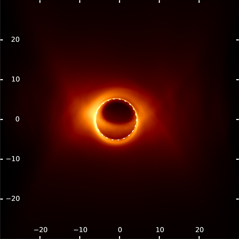
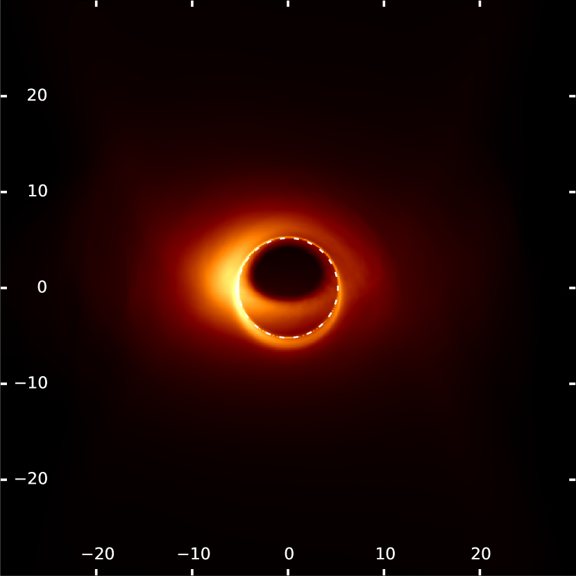
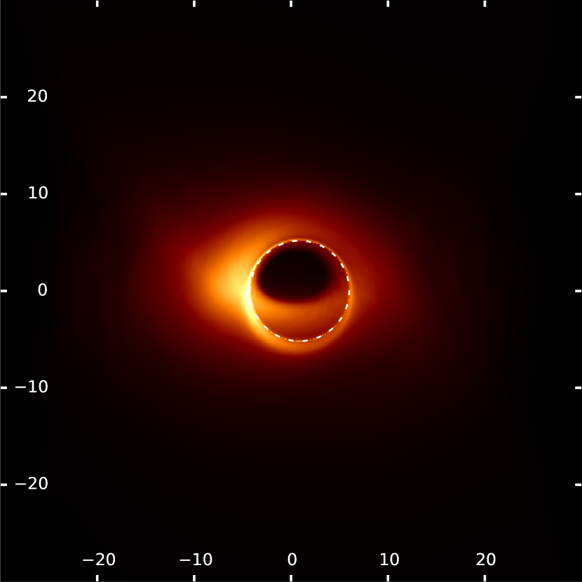
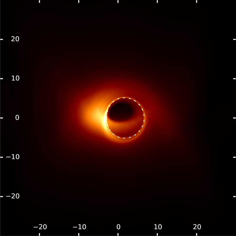
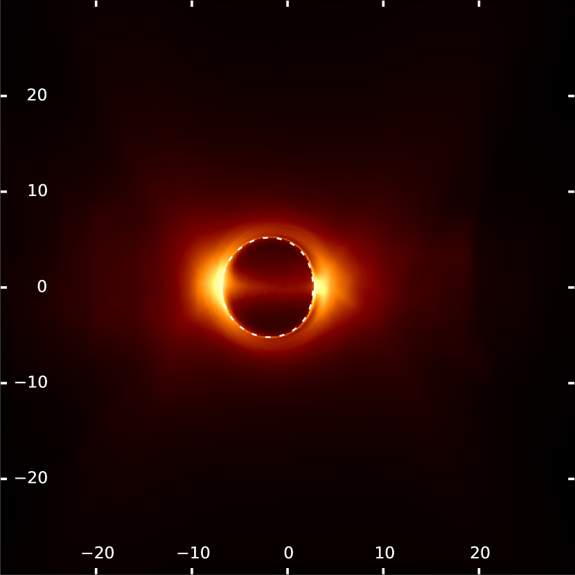
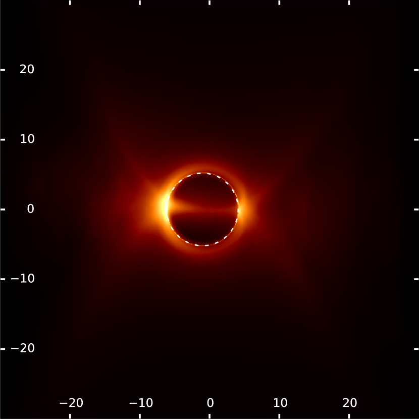
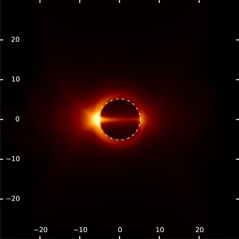
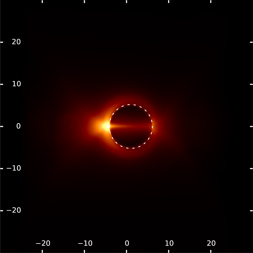
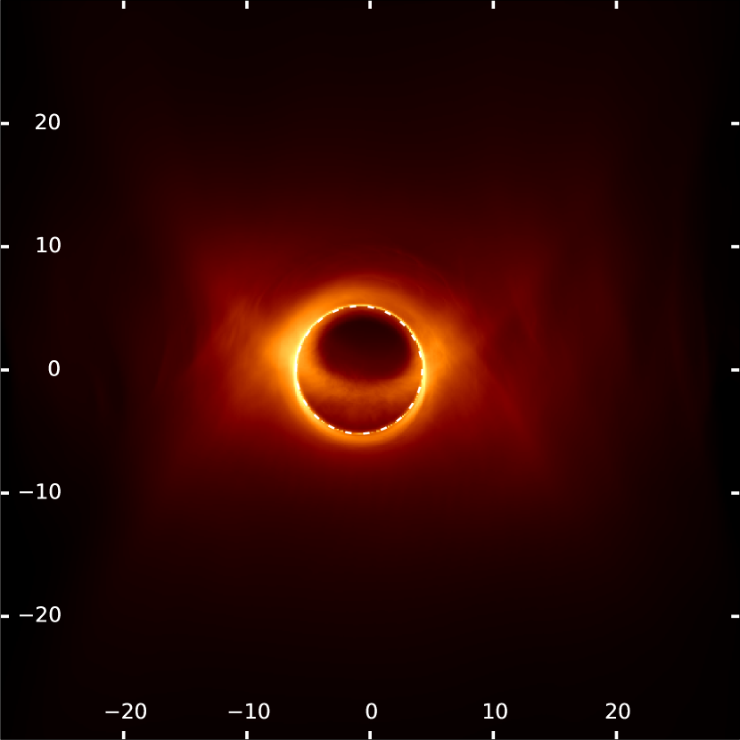
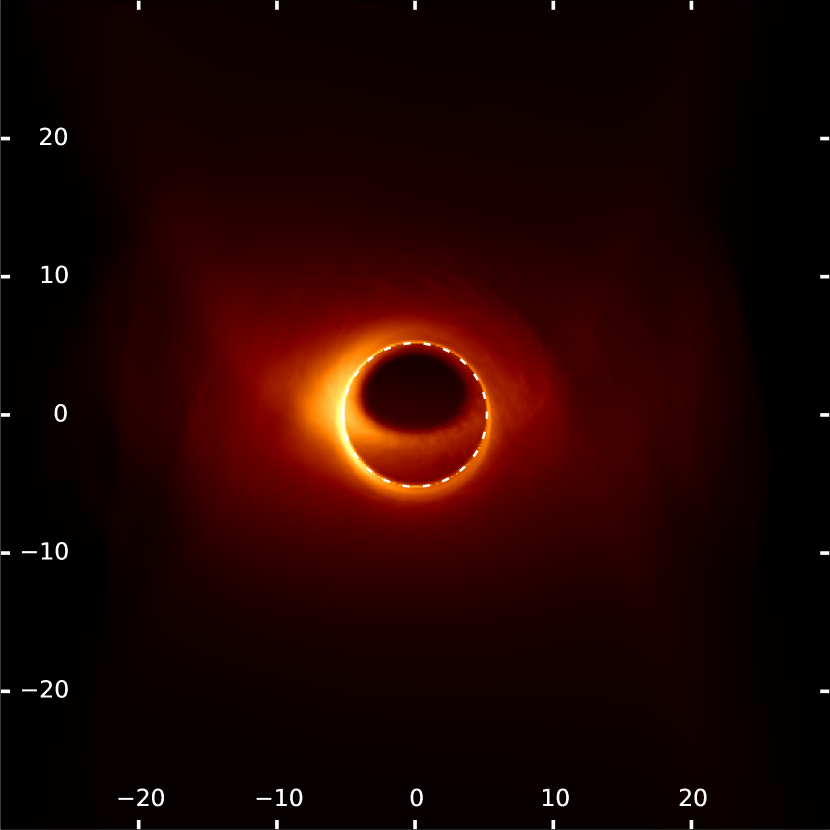
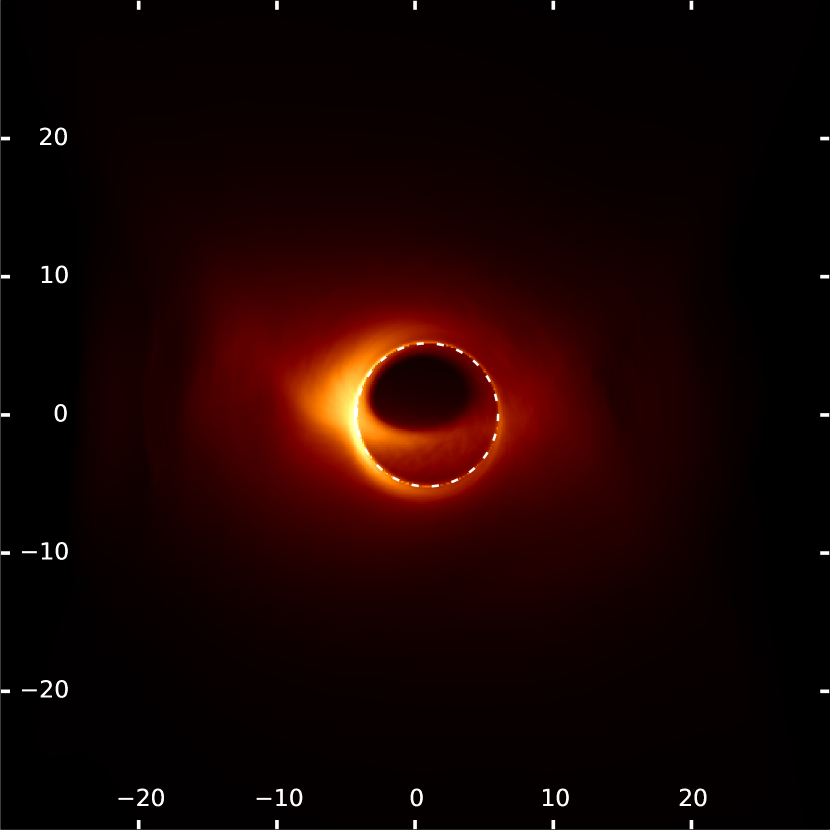
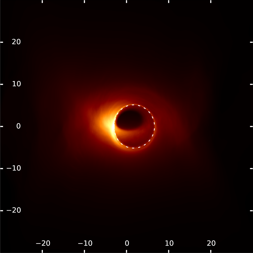
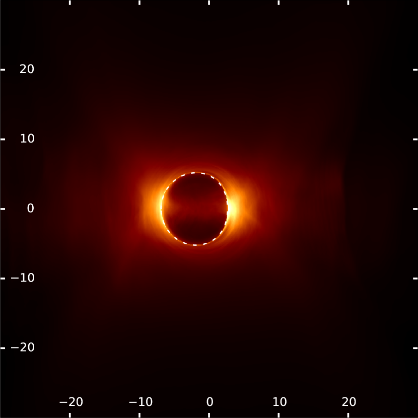
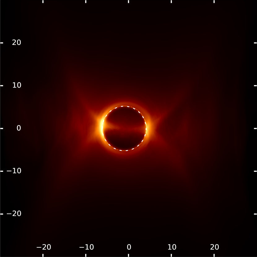
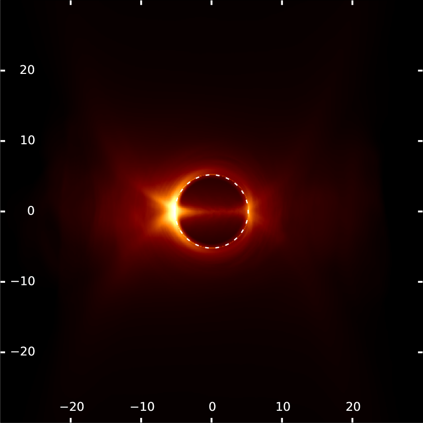
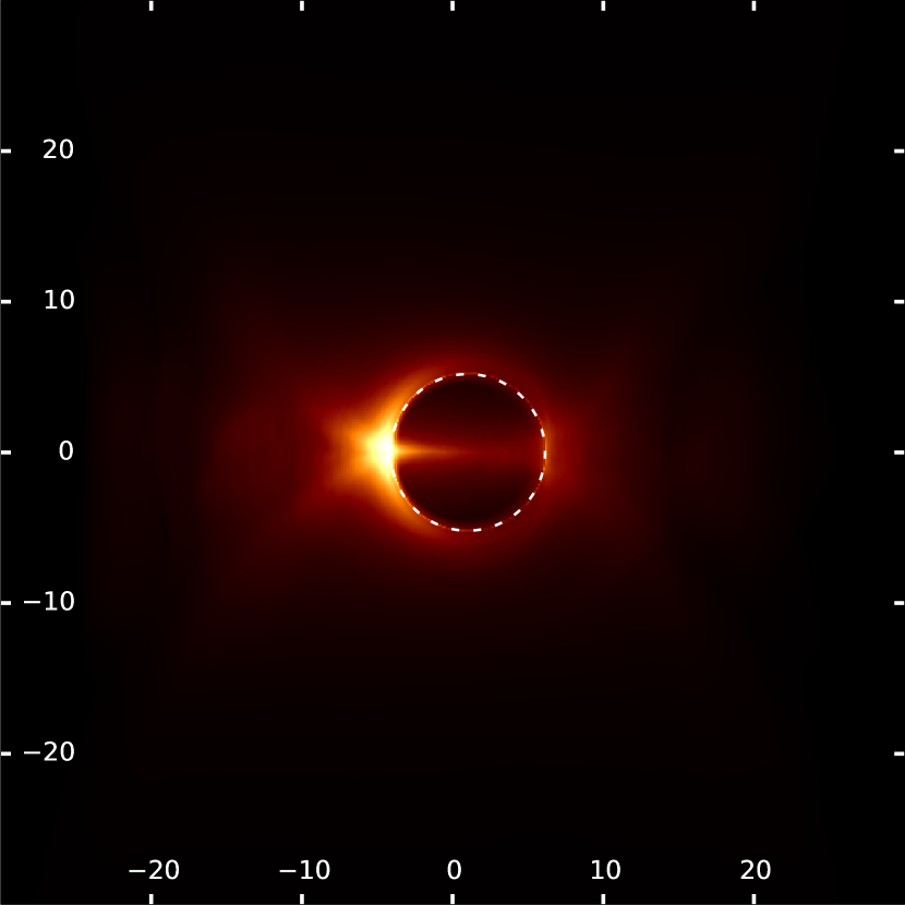
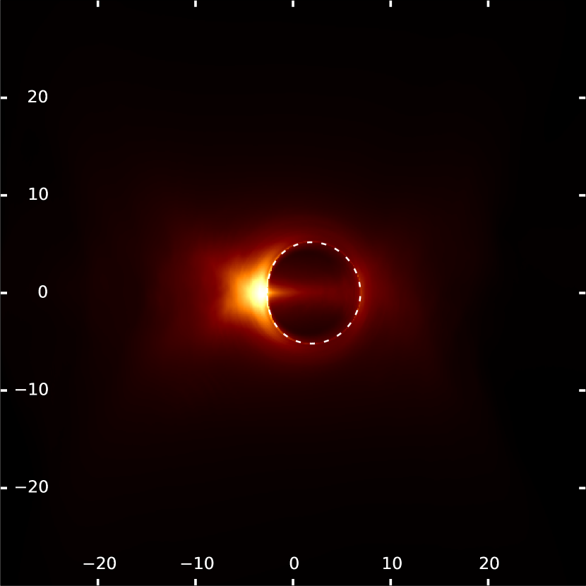
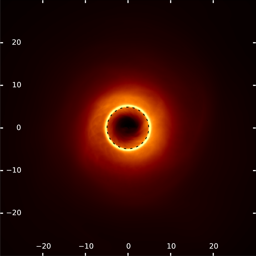
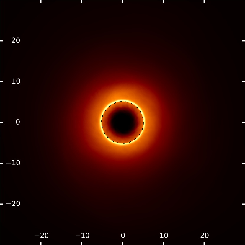
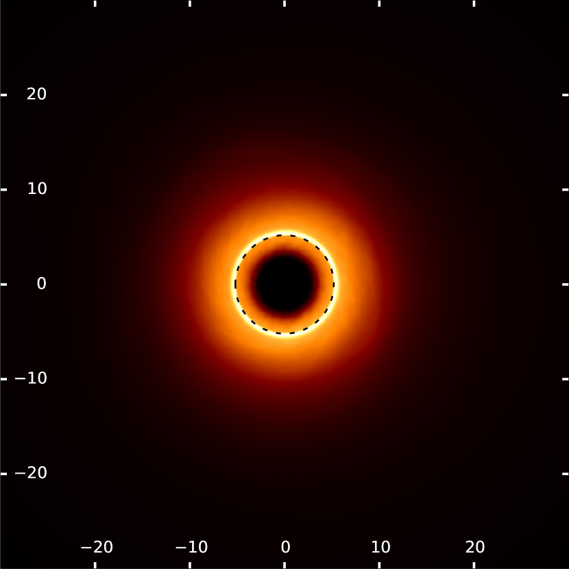
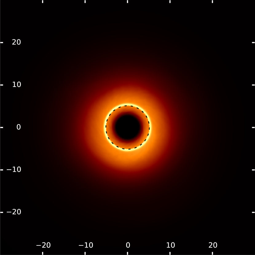
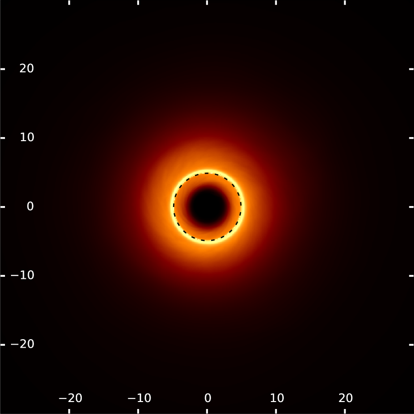
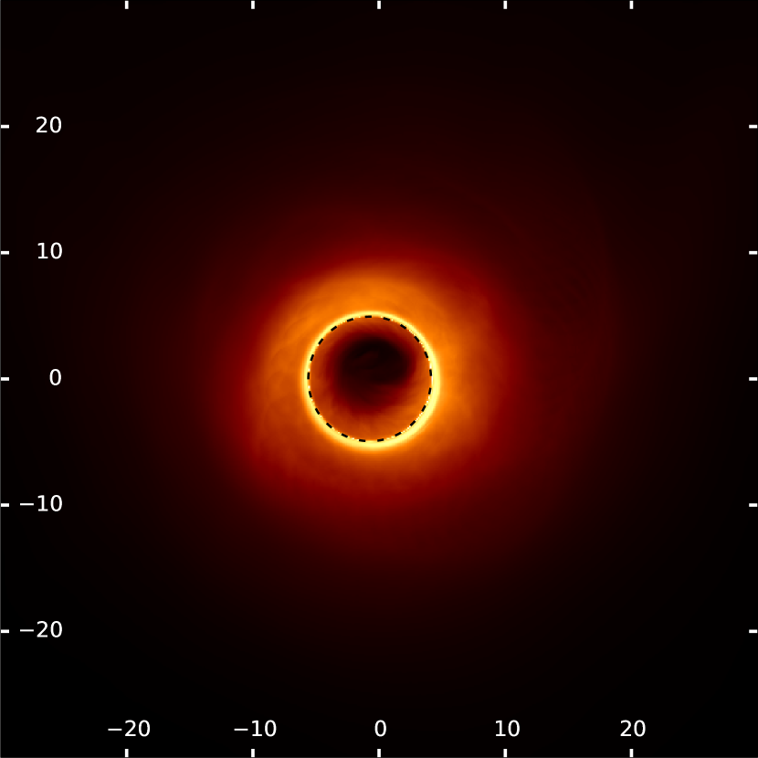
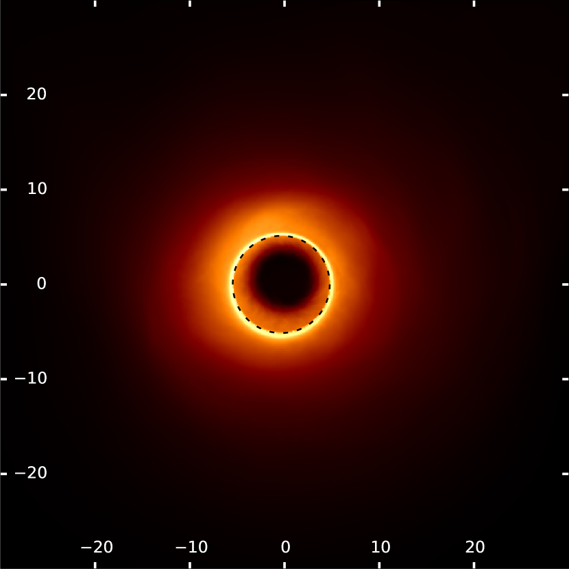
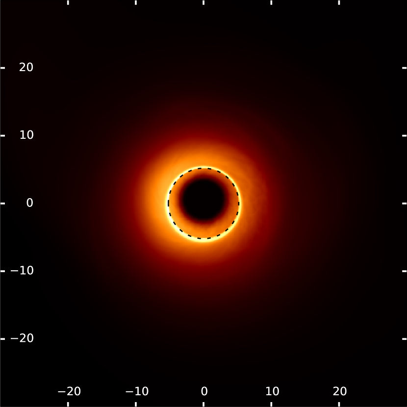
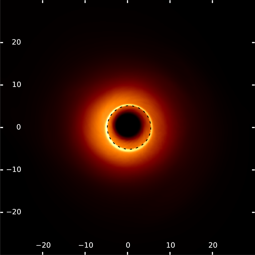
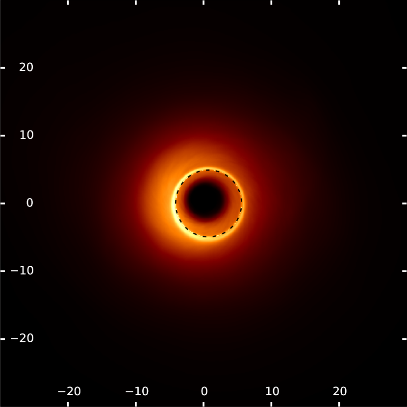
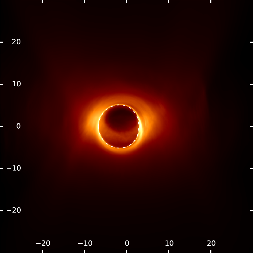
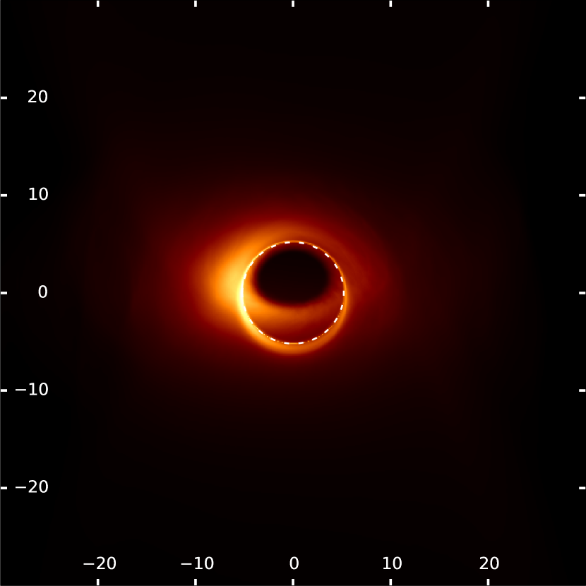
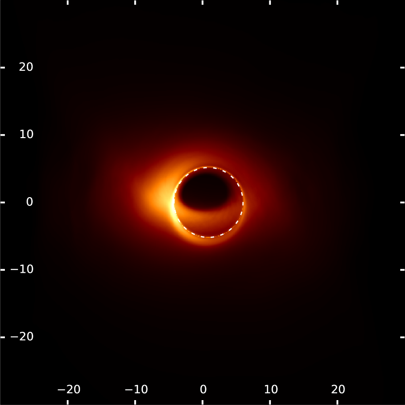
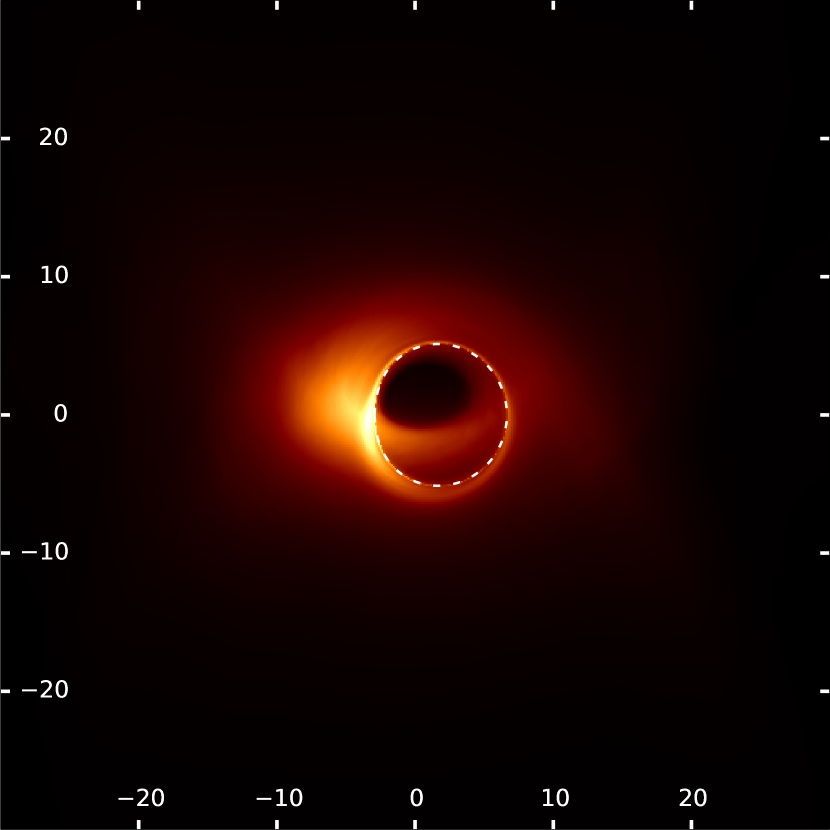
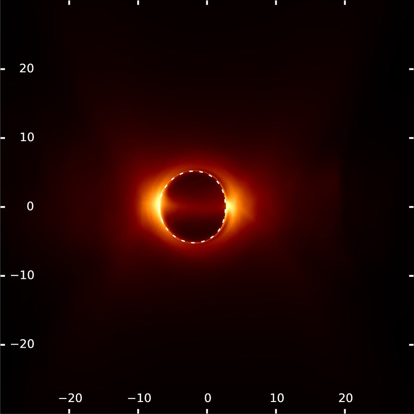
RAPTOR is used to produce images of GRMHD snapshots. One snapshot is used for each image, which is equivalent to using the fast-light approximation, in which the speed of light is effectively treated as being infinite, and the plasma does not evolve while the light propagates through it. For a demonstration that this approximation is appropriate in the present case, see Bronzwaer et al., (2018). In order to simulate the effects of prolonged observations (which typically last hours in the case of EHT), 200 subsequent images are added together, meaning that we average over a temporal range of 2000 (see Section 3.1), or about 12 hours (comparable with one day of EHT observations). Figure 1 shows the effects of time-averaging on intensity maps of our SANE disc model with and . For a more in-depth look at the effects of time-averaging on the observed source size and morphology, see Appendix C.
One of RAPTOR’s key variables is the mass scaling factor, , which determines the overall accretion rate in the simulation (which would otherwise be scale-free, as GRMHD simulations are; see, e.g., Porth et al., (2017)). Generally, lower values of entail a more compact and optically thin source size. RAPTOR also allows calibration of to achieve a desired integrated flux density. The flux densities that were used for calibration in this work take Sgr A* as an archetypical example of a LLAGN; its flux density at GHz is approximately Jy (Doeleman et al.,, 2008). Since we aim to explore a range of possible LLAGN sources, we additionally explore lower fluxes of 1.25 Jy and (in the case of the SANE jet model, which is particularly variable with respect to flux scaling) 0.625 Jy. We shall see that in some models, the appearance of the IS changes drastically based on the flux scaling, while in other models, it is nearly constant. Another reason for exploring lower fluxes is that, for the M87 results, the inner few accounted for roughly half of the flux observed for the unresolved core region (Event Horizon Telescope Collaboration, 2019b, ).
In order to calibrate the time-averaged image to the correct integrated flux density, a binary-search algorithm was used that works in the following way:
-
•
Set and (these are estimates that are set using trial and error).
-
•
Launch 20 RAPTOR runs, evenly distributed over the time range, using .
-
•
Compare the average flux of the 20 runs with the target flux. If lower than target flux, ; if higher than target flux, . If within range of target flux (we chose the range to be ), stop algorithm and return .


Although it has been shown that the time averaging of GRMHD images creates artefacts in the context of a synthetic-data pipeline (Medeiros et al.,, 2018), the time-averaged models offer a clearer, more simplified view of the emitting geometry (by averaging out local, random fluctiations), and illustrate a number of optical effects that are significant to this work.
3.4 Image processing
A recipe is needed to quantify key aspects of a given image, such as the source size. We define an image’s impact parameters, and , to mean the coordinate offset of a particular ray with respect to the vertical and horizontal symmetry axes of the image, respectively. The impact parameters are expressed in terms of the gravitational radius, . All images in this work consist of a grid of 512 by 512 pixels. When constructing estimators for the source size, it is convenient to employ the so-called image moments; the image moment is given by
| (2) |
where and are the pixel indices, and are the image moment’s order in the horizontal and vertical direction, and is the flux density at frequency of pixel . Note that are nonnegative integers.
Using the image moments, various quantities can be constructed that quantify certain aspects of the image, such as an estimate of the size of the emission region. The standard deviation, which is an indicator of the source size, is given by:
| (3) |
The value of depends (except for sources with circular symmetry) on the position angle of the source. Using the image moments, rotation-invariant measures of the source size - namely, the major axis, , and the minor axis, - can be constructed as well. For a more complete discussion of their derivation, please refer to Appendix A.
4 Results
In this section, we present all images and plots produced from our library of GRMHD simulations and corresponding RAPTOR images. In Subsection 4.1, we plot maps of the specific intensity of the source at a frequency of 230 GHz, with the analytical prediction of the shape of the BHS overplotted in each case. Subsection 4.2 contains normalised cross-cut profiles of the intensity maps, in order to get a clearer picture of the (mis)match between BHS and IS. Maps of , the optical depth at our observing frequency of 230 GHz, are presented in Subsection 4.3. Intensity maps of two of our SANE disc models, but at a higher observing frequency of 6 THz (which lies in the infrared range of the electromagnetic spectrum, a different observational window that corresponds to a different appearance of the accretion flow), are shown in Subsection 4.4. Note that tables of and , the major and minor axes of the source, are presented in Appendix E, while tables of , the calibration factor used for RAPTOR, are listed in Appendix F.
4.1 Intensity maps for all models
This subsection contains intensity maps of all GRMHD models, plotted using the square-root scale for additional clarity. The images are categorised in the next four subsections by their quasi-steady-state of the disc (MAD or SANE) and radiative model (disc or jet).
4.1.1 SANE jet models


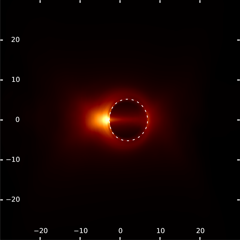
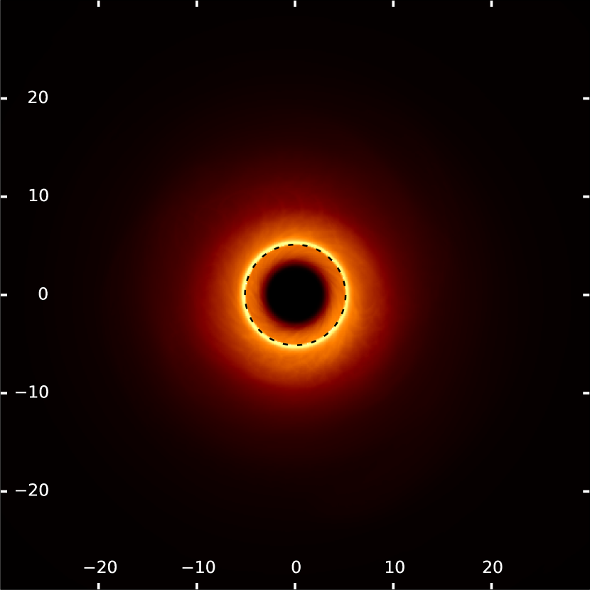
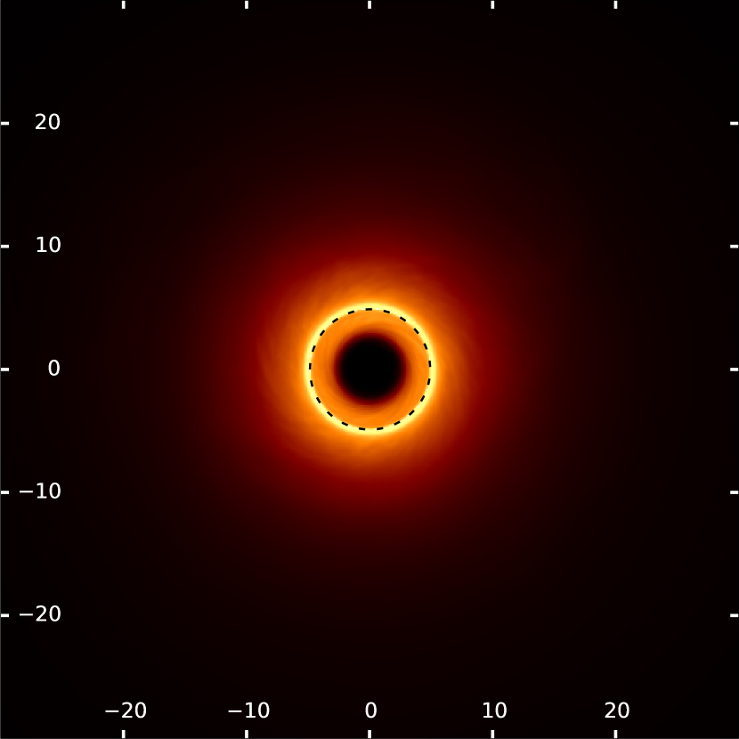
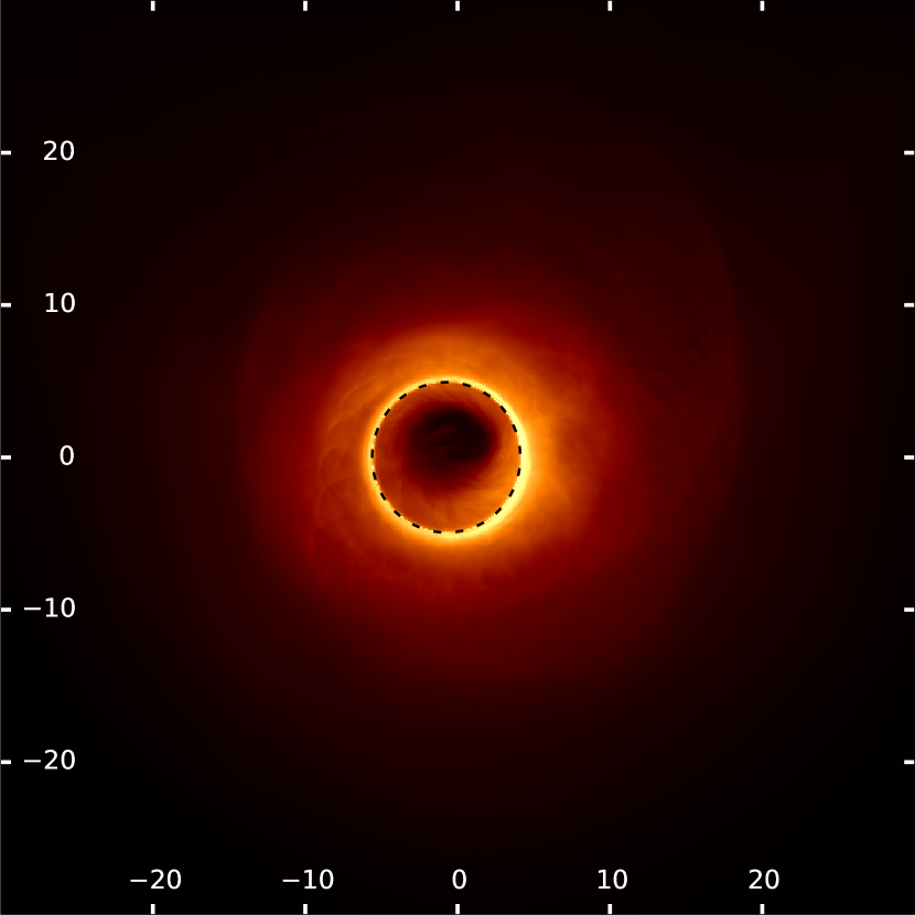
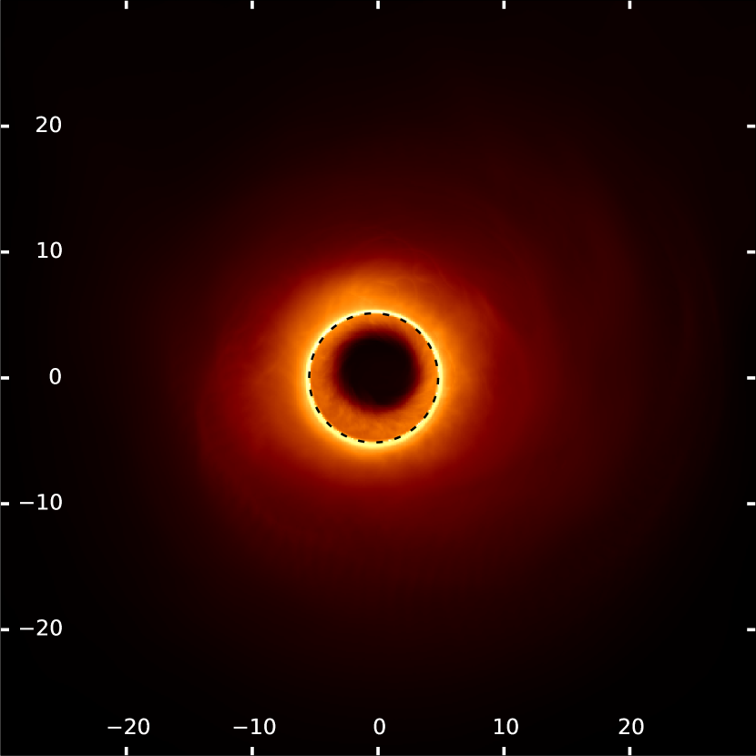
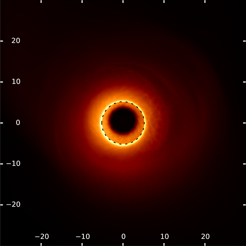
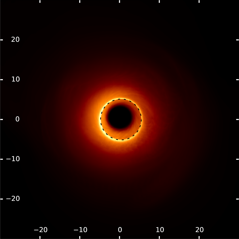
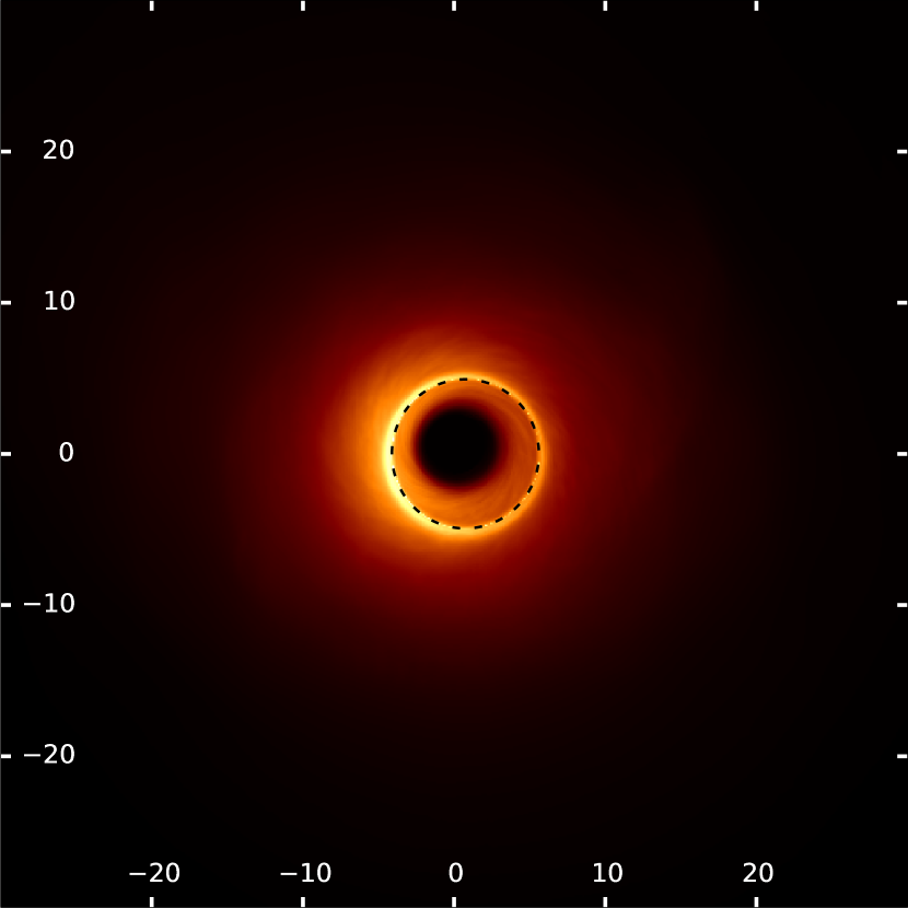
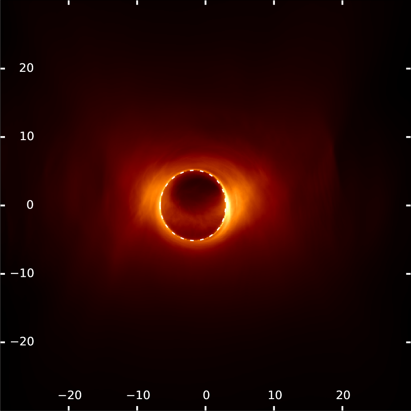
Figures 21, 22, and 23 show the SANE jet model calibrated to 2.5 Jy, 1.25 Jy, and 0.625 Jy, respectively. These two-temperature SANE models are the most diverse in terms of source morphology; many, but not all, show a pronounced jet at 230 GHz. As was shown in Mościbrodzka et al., (2016), for SANE jet models of M87, the counter-jet (which faces away from the observer) can be magnified by the action of the gravitational lens, and thus appear to be larger than the observer-facing jet (Event Horizon Telescope Collaboration, 2019b, ). Note that the optical depth of these models varies significantly between the different fluxes (see Subsection 4.3). In particular, Fig. 2 shows that the SANE jet models viewed with range from completely optically thick at 2.5 Jy (no IS is visible at all in this case) to optically thin at 0.625 Jy, in which case the IS aligns more closely with the BHS. When viewed at low inclination angles, the jet models strongly obscure the BHS at higher fluxes; Fig. 4 shows an IS that is circular and centred on the black hole, but significantly smaller than the BHS. On the other hand, in some optically thick cases, such as the model with and at 2.5 Jy (Fig. 3, the outline of the BHS is clearly visible, despite the presence of an obscuring, optically thick disc.
An interesting effect can be observed in the case for the 1.25 Jy model: this particular model is nearly isotropic in its emission. This can be seen in Table 6: the factor is constant with respect to observer inclination, with an error of a few percent. As Fig. 22 shows, this model has the appearance of an optically thick, homogenous torus. Evidently, the effects of relativistic boosting on one side of the black-hole spin axis and de-boosting on the other side - which are significant at higher inclination angles - cancel out in this case, maintaining a more or less constant flux with respect to the inclination angle, even though the source transitions from being symmetric to asymmetric with respect to the black-hole spin axis.
4.1.2 SANE disc models


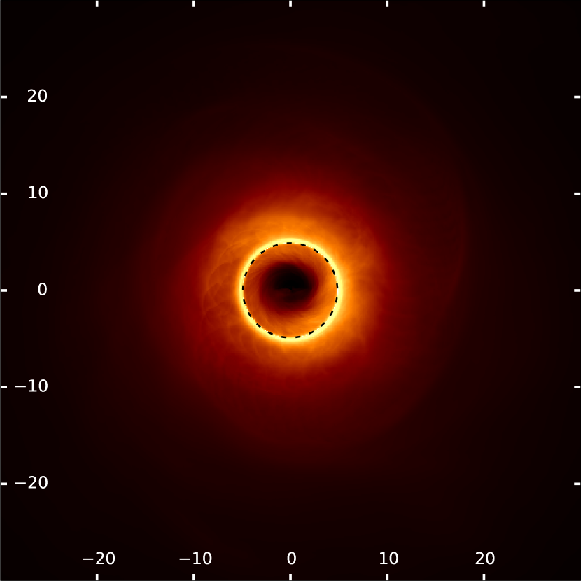
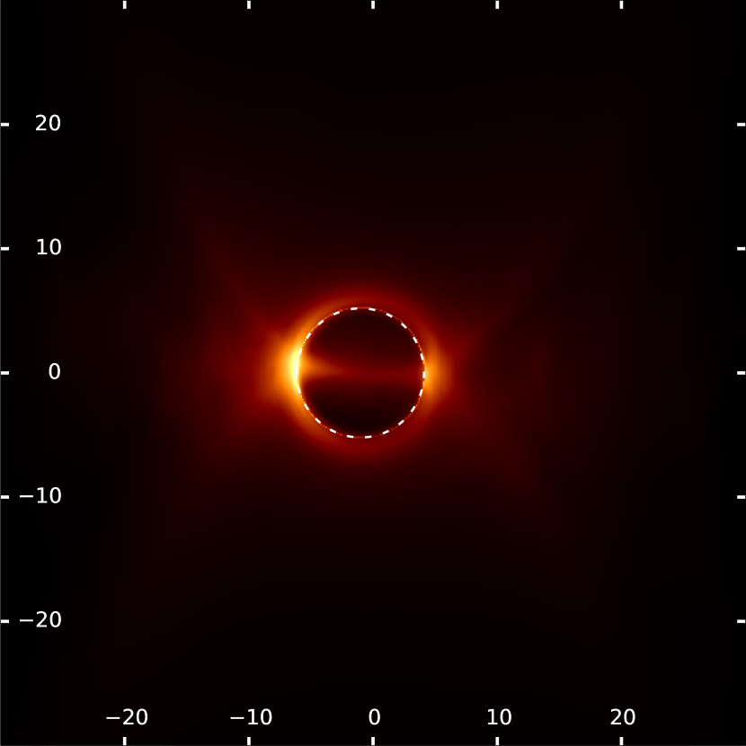
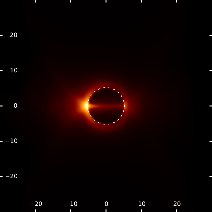
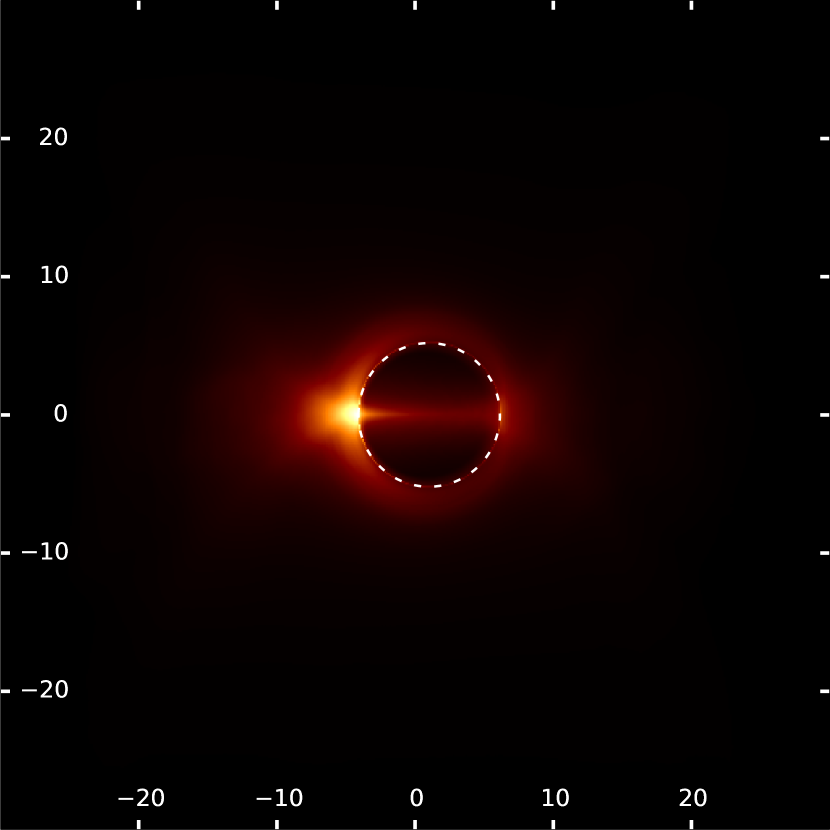
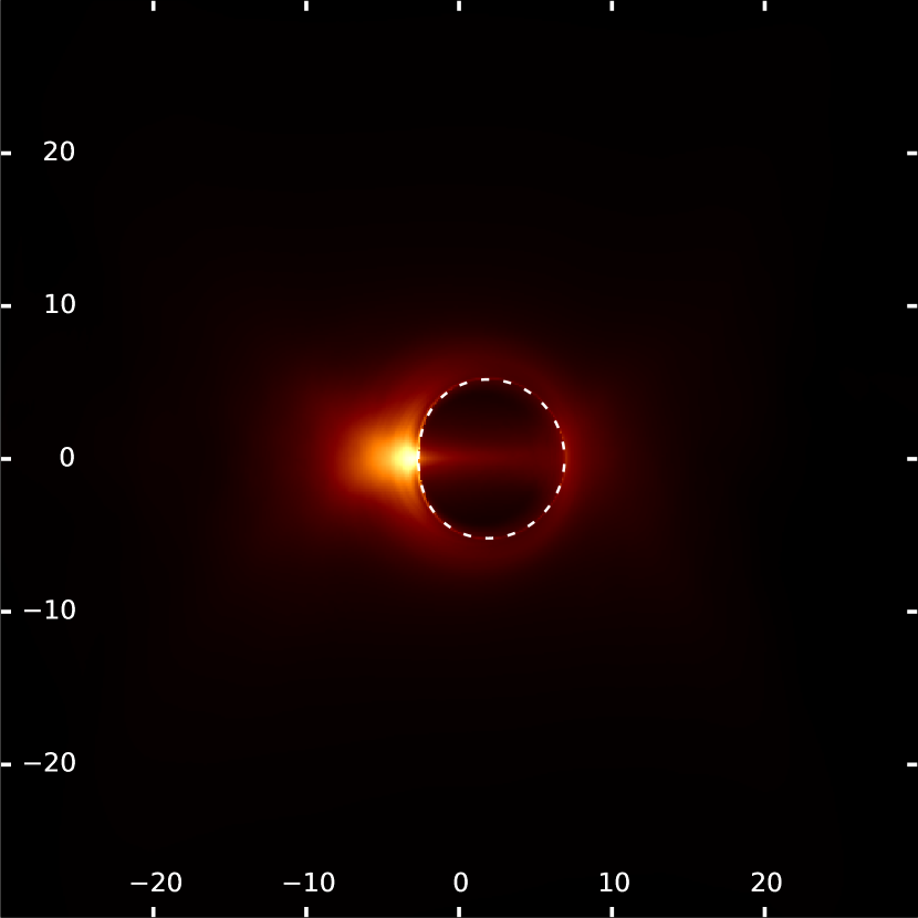
Figures 24 and 25 show the SANE disc models calibrated to 2.5 Jy and 1.25 Jy, respectively. Of all models, the disc models show the greatest variation with respect to spin, when it comes to source size (see Appendix E). Otherwise, their appearance is much more constant than was the case for the SANE jet models. As the SANE disc models have a lower overall accretion rate, they are less optically thick, and show less obscuration effects, than the SANE jet models. For retrograde spins, the SANE disc models, form a large torus, which (due to being geometrically extended) produces a pronounced first-order image just around the photon ring. Thus, the IS aligns with the BHS, although a secondary dark ring may be observed around it (see Subsection 4.2).
Figure 5 shows that the high-spin SANE disc models, viewed at , display a much smaller source size than the jet models. This occurs due to two factors;
-
1.
At high inclinations, the effects of relativistic boosting are more pronounced, exaggerating the importance of one side of the accretion flow while diminishing the other, thus decreasing the source size overall, as discussed by Psaltis et al., 2015a .
-
2.
At high spins, the ISCO shrinks to about the size of the photon sphere, meaning that the orbits are much closer to the black hole, with correspondingly higher velocities. This greatly enhances the effects of relativistic boosting, and consequentially, the de-boosted side of the accretion flow becomes negligible; we only see the boosted region of the accretion flow.
Doeleman et al., (2008) detected horizon-scale structure in Sgr A*, deriving a smaller size than the BHS by assuming a circular gaussian, but also found their data to be consistent with a larger BHS model. Such small source sizes are compatible with a high-spin source that shows strong boosting effects. Later work (Lu et al.,, 2018) refined these models, also showing evidence for emission on scales from a few Rsch to that of the BHS.
The effect of evacuation, discussed in Section 2, is pronounced in the SANE disc models with retrograde spin (Fig. 6). These retrograde models have the largest ISCO, and thus the largest evacuated region within the accretion flow. In such cases, the IS becomes larger than the BHS (Subsection 4.2). This effect is barely visible for the SANE jet models, presumably due to the presence of a bright jet base combined with a colder disc, which acts as a weak emitter near the ISCO.
4.1.3 MAD jet models

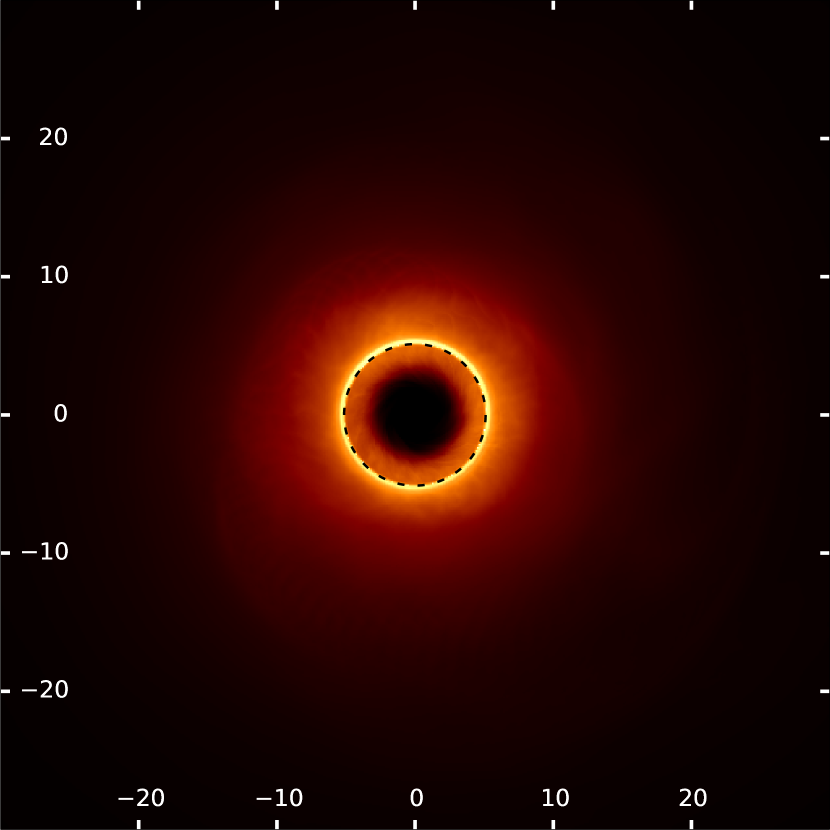
Figures 26 and 28 show the MAD jet model calibrated to 2.5 Jy and 1.25 Jy. One can see at a glance that the source morphologies of these models depends more weakly on the black-hole spin than the source morphologies of the SANE models do (Appendix E). As Table 8 shows, the same is true for , meaning that, much like the morphology, the luminosity of these models is a weaker function of the black-hole spin than for SANE models. A striking feature of these models is the parabolic jet base, which again appears more or less constaint for all spins. In the models, however, this structure appears to be slightly misaligned with respect to the black-hole spin axis, as can be seen in Fig. 7. A future work might explore whether such misalignments occur regularly, and at what time-scales, etc.
Note that none of the MAD models show a clear evacuated region, even at highly retrograde spins, when the ISCO is maximally extended. This is due to the fundamentally different nature of MAD models with respect to SANE models; in MAD models, a ‘pile-up’ of material occurs around a disruption radius, as magnetic fields disrupt the symmetrical accretion flow, causing discrete ‘blobs’ of material to penetrate the disrupted region and accrete on to the black hole with velocities much lower than free fall (Bisnovatyi-Kogan and Ruzmaikin,, 1974). Since the images in this section are time-averaged, the discrete nature of these packets of accreting material is ‘averaged out’, showing a much-simplified geometry in which no clear evacuated region occurs.
4.1.4 MAD disc models

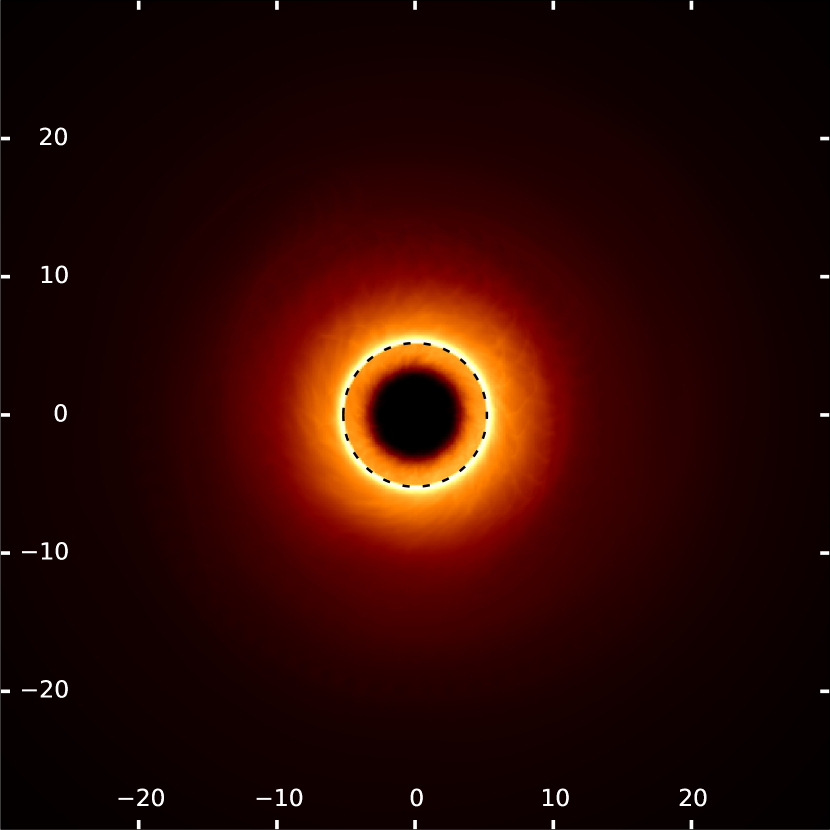
Figures 27 and 29 show the MAD disc model calibrated to 2.5 Jy and 1.25 Jy. As in the case of the MAD jet models, the images are optically thin, and the source sizes and flux-calibration factors are nearly identical (Appendices E and F, see also Fig. 8). Again, all IS’s match the BHS, and there is no clear evacuated region within the ISCO (Subsection 4.2). In other words, the single-temperature MAD disc model is visually very similar to the two-temperature MAD jet model, unlike the case of SANE, where the appearance of the two models differed drastically. This is due to the fact that for most of the material in the MAD disc, , which makes the temperature ratio of the electrons and the ions insensitive to the -parametrization (Event Horizon Telescope Collaboration, 2019b, ).
4.2 Intensity profiles
In this section we examine the relationship between the BHS and the IS more closely, by plotting certain normalised cross-cut profiles of the intensity maps presented in Section 4.1. The cuts are made in the directions parallel to, and perpendicular to, the black-hole spin axis, at the locations where the BHS is maximally extended in those directions. We thus obtain the largest possible cross-section of the BHS. In each case, we indicate the theoretically predicted location of the BHS with red, vertical lines.
4.2.1 Intensity profiles of SANE models
Figure 9 shows the high-spin SANE models at low inclination, which is one of the most challenging models in terms of visualising the BHS, especially the jet model, for which the peak intensity does not occur within the EHT’s error bars for the shadow measurement (indicated with the shaded blue regions). The disc models, on the other hand, do peak near the BHS, although they show a mildly obscured IS.
Figure 10 shows the highly retrograde-spin models. In this case, the flow is overall more optically thin (see Section 4.3), and the BHS can be more clearly seen. However, the effect of evacuation - i.e., the lack of radiating matter within the ISCO - can enlarge the perceived IS (see, for example, the disc models in the lower panels of those figures).


4.2.2 Intensity profiles of MAD models
The MAD models are, overall, much less optically thick than the SANE models under the circumstances considered here (see Section 4.3). Consequently, the IS matches the BHS much better, and in most cases, the intensity profile peaks near the photon ring (i.e., within the EHT’s error bars). It is also interesting to note that the lensing ring introduced by Gralla et al., (2019) appears quite distinctly for these models, due to the fact that the flow is optically thin and torus-shaped.
Figure 11 shows the high-spin MAD models with . For these models, obscuration occurs, when the accretion flow passes in front of the BHS. Figure 12 shows the highly retrograde-spin MAD models. For these models, the intensity profile peaks near the photon ring in each case. Intriguingly, the rightmost peaks of the intensity profiles are higher than the peaks left of the BHS, even though the overall sense of rotation of the accretion flow suggests that the leftmost peaks are highly boosted (as occurs in the prograde-spin models). This suggests that the flow’s rotation slows down near the horizon, possibly even reversing. This phenomenon is discussed in (Event Horizon Telescope Collaboration, 2019b, ).


4.3 Optical-depth maps
In this section we present maps of , the optical depth along null geodesics, for some of our models, in order to examine the optical behavior of the accretion flow more closely. Note that the maps in this section are plotted in linear scale. Figures 13 and 14 show optical depth maps, for various spins and inclinations, of our SANE jet models at integrated flux densities of 2.5 Jy and 0.625 Jy, respectively. The maps plot up to a maximum of 3, at which optical depth less than 5% of background radiation is transmitted, and we consider the BHS to be obscured. Note the optical depth of the high-prograde-spin SANE jet models at higher fluxes in particular, which almost completely disappears at the lower flux. Figure 15 shows maps of for our MAD jet model at 1.25 Jy. Note that this model is almost completely optically thin, never reaching the maximum optical depth of 3.


4.4 High-frequency intensity maps
Although the BHS is achromatic, the same is not true for the IS (Section 2). Depending on the black hole’s mass and accretion rate, the frequency at which the source becomes optically thin (and thus displays a clear BHS) may be different (Falcke et al.,, 2000). However, crucially, since most AGN show a power-law regime in their spectrum, it is always possible to pick frequency in the power-law regime where the source is optically thin (see, e.g., Falcke et al., (2004)). For the model considered in this paper, the observing frequency we have used so far (230 GHz) lies below the SED’s peak, and below its power-law region (Mościbrodzka et al.,, 2009). Thus, we may expect the source to become more optically thin at higher frequencies, potentially obtaining a better match between the BHS and the IS in that regime.
To demonstrate the achromaticity of the BHS, as well as the decreasing optical depth at higher frequencies, we plot intensity maps of two SANE disc models at 2.5 Jy - specifically, the and (panels l and j in Fig. 24, respectively) - at an observing frequency of 6 THz in Fig. 16; this frequency was chosen in order to examine the appearance of the IS in a different observational window (infrared). Intensity profiles for these models, at both 230 GHz and 6 THz, are shown in Fig. 17.
Note that, at this higher (mid-IR) frequency, the overall source size is reduced, and a more pronounced lensing ring is shown. Figure 17 shows that, at 6 THz, the peaks of the intensity profiles lie within the EHT’s error bars, although some obstruction remains in the high-prograde-spin case.


5 Discussion
In the context of accreting LLAGN, we have discussed the differences between the BHS, which depends only on the geometry of spacetime and the location of the observer, and the observable IS, which depends also on plasma conditions. We argue that, if the emission region is compact and optically thin, the IS matches the BHS to within the precision of measurements by the EHT. It was argued by Gralla et al., (2019) that circumstances can none the less occur in which the IS differs significantly from the BHS, even if the IS is circular, or the source is ring-like. Their conclusions are based on analytical, spherically symmetric, optically thin accretion models that do not take the full plasma dynamics and radiation effects into account, and, in our opinion, they cannot be applied to realistic astrophysical scenarios without further refinement. In that context, we identify two specific effects that can cause the IS to deviate from the BHS in the physically motivated case presently considered (of a geometrically thick, radiatively inefficient accretion flow): obscuration of the BHS by a part of the accretion flow that passes in front of it, and enlargement of the IS due to the lack of emission coming from the evacuated innermost region of the accretion flow, which scales with the ISCO in the case of SANE models (see Appendix B).
Narayan et al., (2019) showed that these effects do not arise in the case of spherical accretion flows; in this work, we extend that analysis to the case of non-spherical, GRMHD-based models of the accretion flow. To this end, we have constructed a library of RAPTOR images of a set of GRMHD simulations produced using the GRMHD code BHAC for the 2017 EHT campaign. GRMHD simulations of both the MAD and SANE types were used; different spins (from retrograde to prograde) and inclination angles were considered; two radiative models (disc- and jet-based) were considered, and finally, the analysis was repeated at two different flux calibrations, to investigate a wider regime of LLAGN models.
It was found that virtually all MAD models show clear IS’s that match the BHS well. At the fluxes considered in this paper, the MAD models were highly optically thin. The emission region was compact in each case; no evacuation effect is seen, although obscuration of the BHS does occur at inclination angles near 90 degrees. The morphology of the single-temperature disc model is quite similar to that of the two-temperature jet model. Note that we have considered time-averaged images of the accretion flow in this work; instantaneous snapshots of the GRMHD data show a more complex morphology, in which the discrete packets of accreting material aren’t ‘smeared out’ in the azimuthal direction (a quantitative look at the effects of the time-averaging procedure on the appearance of the source is presented in Appendix C). The effect of relativistic boosting are less apparent than in the SANE case. In the case of a retrograde accretion flow, the effects of relativistic boosting can be reversed; the highest intensity in those cases occurs on the side of the image where the large-scale accretion flow is receding from the observer.
For our SANE models, the relationship between the BHS and the IS is more complicated. The morphology of the two-temperature jet model, in particular, is extremely sensitive to both the black-hole spin and the integrated flux density; it can range from optically thick to optically thin. In the optically thick case, the IS can be highly distorted. In the case of high prograde spin viewed at inclination angles near 90 degrees, the shadow may disappear entirely. At lower inclination angles, the BHS tends to be partially obscured by optically thick material, rendering the IS smaller than the BHS. The SANE disc models, lacking both a bright jet base and an obscuring, colder disc, tend to show more clear shadows than the SANE jet models. However, both obscuration and evacuation (particularly for retrograde spins) can significantly affect the appearance of the IS. In all cases, the effects of evacuation disappear at high prograde spin.
We conclude that, for GRMHD-based models of LLAGN that are optically thin and compact (so that the effects of obscuration and evacuation are limited), the IS matches the BHS to within an accuracy of 5%. Observations of LLAGN that resemble SANE models, particularly two-temperature jet models, will be challenging on account of the much more varied appearances such models can take, including forms that show no IS at all. Our examination of high-frequency (6 THz) intensity maps of the SANE disc model illustrate that the frequency at which the inner region of our models becomes optically thin is strongly model-dependent, and scales with the accretion rate and mass of the black hole (Falcke et al.,, 2004). The appropriate observing frequency for observing a clear BHS must therefore be carefully chosen.
Acknowledgements
This work is supported by the ERC Synergy Grant "BlackHoleCam: Imaging the Event Horizon of Black Holes" (Grant 610058). ZY is supported by a Leverhulme Trust Early Career Fellowship. TB thanks C. Brinkerink, S. Issaoun, L. Medeiros, F. Özel, and D. Psaltis for insightful comments regarding the manuscript. The authors thank Bart Ripperda and the anonymous referee for helpful feedback. This work has made use of NASA’s Astrophysics Data System (ADS).
Data Availability
The data underlying this article (both the raw RAPTOR output as well as the processed plots) will be shared on reasonable request to the corresponding author (t.bronzwaer@astro.ru.nl).
References
- Ball et al., (2016) Ball, D., Özel, F., Psaltis, D., and Chan, C.-k. (2016). Particle Acceleration and the Origin of X-Ray Flares in GRMHD Simulations of SGR A. ApJ, 826:77.
- Bardeen et al., (1972) Bardeen, J. M., Press, W. H., and Teukolsky, S. A. (1972). Rotating Black Holes: Locally Nonrotating Frames, Energy Extraction, and Scalar Synchrotron Radiation. ApJ, 178:347–370.
- Bisnovatyi-Kogan and Ruzmaikin, (1974) Bisnovatyi-Kogan, G. S. and Ruzmaikin, A. A. (1974). The Accretion of Matter by a Collapsing Star in the Presence of a Magnetic Field. Ap&SS, 28(1):45–59.
- Boehle et al., (2016) Boehle, A., Ghez, A. M., Schödel, R., Meyer, L., Yelda, S., Albers, S., Martinez, G. D., Becklin, E. E., Do, T., Lu, J. R., Matthews, K., Morris, M. R., Sitarski, B., and Witzel, G. (2016). An Improved Distance and Mass Estimate for Sgr A* from a Multistar Orbit Analysis. ApJ, 830:17.
- Broderick, (2006) Broderick, A. E. (2006). Radiative transfer along rays in curved space-times. MNRAS, 366:L10–L12.
- Broderick et al., (2014) Broderick, A. E., Johannsen, T., Loeb, A., and Psaltis, D. (2014). Testing the No-hair Theorem with Event Horizon Telescope Observations of Sagittarius A*. ApJ, 784:7.
- Broderick and Loeb, (2006) Broderick, A. E. and Loeb, A. (2006). Testing General Relativity with High-Resolution Imaging of Sgr A*. In Schödel, R., Bower, G. C., Muno, M. P., Nayakshin, S., and Ott, T., editors, Journal of Physics Conference Series, volume 54 of Journal of Physics Conference Series, pages 448–455.
- Bronzwaer et al., (2018) Bronzwaer, T., Davelaar, J., Younsi, Z., Mościbrodzka, M., Falcke, H., Kramer, M., and Rezzolla, L. (2018). RAPTOR I: Time-dependent radiative transfer in arbitrary spacetimes. ArXiv e-prints.
- Chan et al., (2013) Chan, C.-k., Psaltis, D., and Özel, F. (2013). GRay: A Massively Parallel GPU-based Code for Ray Tracing in Relativistic Spacetimes. ApJ, 777:13.
- Chan et al., (2015) Chan, C.-K., Psaltis, D., Özel, F., Narayan, R., and Sadowski, A. (2015). The Power of Imaging: Constraining the Plasma Properties of GRMHD Simulations using EHT Observations of Sgr A*. ApJ, 799(1):1.
- Chatterjee et al., (2020) Chatterjee, K., Younsi, Z., Liska, M., Tchekhovskoy, A., Markoff, S., Yoon, D., van Eijnatten, D., Hesp, C., Ingram, A., and van der Klis, M. (2020). Observational signatures of disk and jet misalignment in images of accreting black holes. arXiv e-prints, page arXiv:2002.08386.
- Davelaar et al., (2018) Davelaar, J., Mościbrodzka, M., Bronzwaer, T., and Falcke, H. (2018). General relativistic magnetohydrodynamical -jet models for Sagittarius A*. A&A, 612:A34.
- Davelaar et al., (2019) Davelaar, J., Olivares, H., Porth, O., Bronzwaer, T., Janssen, M., Roelofs, F., Mizuno, Y., Fromm, C. M., Falcke, H., and Rezzolla, L. (2019). Modeling non-thermal emission from the jet-launching region of M 87 with adaptive mesh refinement. A&A, 632:A2.
- Dexter and Agol, (2009) Dexter, J. and Agol, E. (2009). A Fast New Public Code for Computing Photon Orbits in a Kerr Spacetime. ApJ, 696:1616–1629.
- Dexter et al., (2010) Dexter, J., Agol, E., Fragile, P. C., and McKinney, J. C. (2010). The Submillimeter Bump in Sgr A* from Relativistic MHD Simulations. ApJ, 717:1092–1104.
- Dexter et al., (2020) Dexter, J., Tchekhovskoy, A., Jiménez-Rosales, A., Ressler, S. M., Bauböck, M., Dallilar, Y., de Zeeuw, P. T., Eisenhauer, F., von Fellenberg, S., Gao, F., Genzel, R., Gillessen, S., Habibi, M., Ott, T., Stadler, J., Straub, O., and Widmann, F. (2020). Sgr A* near-infrared flares from reconnection events in a magnetically arrested disc. arXiv e-prints, page arXiv:2006.03657.
- Doeleman et al., (2008) Doeleman, S. S., Weintroub, J., Rogers, A. E. E., Plambeck, R., Freund, R., Tilanus, R. P. J., Friberg, P., Ziurys, L. M., Moran, J. M., Corey, B., Young, K. H., Smythe, D. L., Titus, M., Marrone, D. P., Cappallo, R. J., Bock, D. C.-J., Bower, G. C., Chamberlin, R., Davis, G. R., Krichbaum, T. P., Lamb, J., Maness, H., Niell, A. E., Roy, A., Strittmatter, P., Werthimer, D., Whitney, A. R., and Woody, D. (2008). Event-horizon-scale structure in the supermassive black hole candidate at the Galactic Centre. Nature, 455:78–80.
- (18) Event Horizon Telescope Collaboration (2019a). First M87 Event Horizon Telescope Results. I. The Shadow of the Supermassive Black Hole. ApJ, 875(1):L1.
- (19) Event Horizon Telescope Collaboration (2019b). First M87 Event Horizon Telescope Results. V. Physical Origin of the Asymmetric Ring. ApJ, 875(1):L5.
- (20) Event Horizon Telescope Collaboration (2019c). First M87 Event Horizon Telescope Results. VI. The Shadow and Mass of the Central Black Hole. ApJ, 875(1):L6.
- Falcke et al., (2004) Falcke, H., Körding, E., and Markoff, S. (2004). A scheme to unify low-power accreting black holes. Jet-dominated accretion flows and the radio/X-ray correlation. A&A, 414:895–903.
- Falcke et al., (1993) Falcke, H., Mannheim, K., and Biermann, P. L. (1993). The Galactic Center radio jet. A&A, 278:L1–L4.
- Falcke and Markoff, (2013) Falcke, H. and Markoff, S. B. (2013). Toward the event horizon the supermassive black hole in the Galactic Center. Classical and Quantum Gravity, 30(24):244003.
- Falcke et al., (2000) Falcke, H., Melia, F., and Agol, E. (2000). Viewing the Shadow of the Black Hole at the Galactic Center. ApJ, 528:L13–L16.
- Fishbone and Moncrief, (1976) Fishbone, L. G. and Moncrief, V. (1976). Relativistic fluid disks in orbit around Kerr black holes. ApJ, 207:962–976.
- Gammie et al., (2003) Gammie, C. F., McKinney, J. C., and Tóth, G. (2003). HARM: A Numerical Scheme for General Relativistic Magnetohydrodynamics. ApJ, 589:444–457.
- Gralla et al., (2019) Gralla, S. E., Holz, D. E., and Wald, R. M. (2019). Black hole shadows, photon rings, and lensing rings. Phys. Rev. D, 100(2):024018.
- Gravity Collaboration, (2020) Gravity Collaboration (2020). Detection of the Schwarzschild precession in the orbit of the star S2 near the Galactic centre massive black hole. A&A, 636:L5.
- Gravity Collaboration et al., (2018) Gravity Collaboration, Abuter, R., Amorim, A., Bauböck, M., Berger, J. P., Bonnet, H., Brand ner, W., Clénet, Y., Coudé Du Foresto, V., de Zeeuw, P. T., Deen, C., Dexter, J., Duvert, G., Eckart, A., Eisenhauer, F., Förster Schreiber, N. M., Garcia, P., Gao, F., Gendron, E., Genzel, R., Gillessen, S., Guajardo, P., Habibi, M., Haubois, X., Henning, T., Hippler, S., Horrobin, M., Huber, A., Jiménez-Rosales, A., Jocou, L., Kervella, P., Lacour, S., Lapeyrère, V., Lazareff, B., Le Bouquin, J. B., Léna, P., Lippa, M., Ott, T., Panduro, J., Paumard, T., Perraut, K., Perrin, G., Pfuhl, O., Plewa, P. M., Rabien, S., Rodríguez-Coira, G., Rousset, G., Sternberg, A., Straub, O., Straubmeier, C., Sturm, E., Tacconi, L. J., Vincent, F., von Fellenberg, S., Waisberg, I., Widmann, F., Wieprecht, E., Wiezorrek, E., Woillez, J., and Yazici, S. (2018). Detection of orbital motions near the last stable circular orbit of the massive black hole SgrA*. A&A, 618:L10.
- Hertog and Hartle, (2017) Hertog, T. and Hartle, J. (2017). Observational Implications of Fuzzball Formation. arXiv e-prints, page arXiv:1704.02123.
- Hertog et al., (2019) Hertog, T., Lemmens, T., and Vercnocke, B. (2019). Imaging higher-dimensional black objects. Phys. Rev. D, 100(4):046011.
- Heusler, (1996) Heusler, M., editor (1996). Black hole uniqueness theorems., volume 6 of Cambridge Lecture Notes in Physics.
- Issaoun et al., (2019) Issaoun, S., Johnson, M. D., Blackburn, L., Brinkerink, C. D., Mościbrodzka, M., Chael, A., Goddi, C., Martí-Vidal, I., Wagner, J., Doeleman, S. S., Falcke, H., Krichbaum, T. P., Akiyama, K., Bach, U., Bouman, K. L., Bower, G. C., Broderick, A., Cho, I., Crew, G., Dexter, J., Fish, V., Gold, R., Gómez, J. L., Hada, K., Hernández-Gómez, A., Janßen, M., Kino, M., Kramer, M., Loinard, L., Lu, R. S., Markoff, S., Marrone, D. P., Matthews, L. D., Moran, J. M., Müller, C., Roelofs, F., Ros, E., Rottmann, H., Sanchez, S., Tilanus, R. P. J., de Vicente, P., Wielgus, M., Zensus, J. A., and Zhao, G. Y. (2019). The Size, Shape, and Scattering of Sagittarius A* at 86 GHz: First VLBI with ALMA. ApJ, 871(1):30.
- Johannsen and Psaltis, (2010) Johannsen, T. and Psaltis, D. (2010). Testing the No-hair Theorem with Observations in the Electromagnetic Spectrum. II. Black Hole Images. ApJ, 718(1):446–454.
- Leung et al., (2011) Leung, P. K., Gammie, C. F., and Noble, S. C. (2011). Numerical Calculation of Magnetobremsstrahlung Emission and Absorption Coefficients. ApJ, 737:21.
- Lu et al., (2018) Lu, R.-S., Krichbaum, T. P., and Roy, A. L. e. a. (2018). Detection of Intrinsic Source Structure at 3 Schwarzschild Radii with Millimeter-VLBI Observations of SAGITTARIUS A*. ApJ, 859(1):60.
- Luminet, (1979) Luminet, J.-P. (1979). Image of a spherical black hole with thin accretion disk. A&A, 75:228–235.
- Mao et al., (2017) Mao, S. A., Dexter, J., and Quataert, E. (2017). The impact of non-thermal electrons on event horizon scale images and spectra of Sgr A*. MNRAS, 466(4):4307–4319.
- Medeiros et al., (2018) Medeiros, L., Chan, C.-k., Özel, F., Psaltis, D., Kim, J., Marrone, D. P., and Sadowski, A. (2018). GRMHD Simulations of Visibility Amplitude Variability for Event Horizon Telescope Images of Sgr A*. ApJ, 856(2):163.
- Mizuno et al., (2018) Mizuno, Y., Younsi, Z., Fromm, C. M., Porth, O., De Laurentis, M., Olivares, H., Falcke, H., Kramer, M., and Rezzolla, L. (2018). The current ability to test theories of gravity with black hole shadows. Nature Astronomy.
- Mościbrodzka and Falcke, (2013) Mościbrodzka, M. and Falcke, H. (2013). Coupled jet-disk model for Sagittarius A*: explaining the flat-spectrum radio core with GRMHD simulations of jets. A&A, 559:L3.
- Mościbrodzka et al., (2016) Mościbrodzka, M., Falcke, H., and Shiokawa, H. (2016). General relativistic magnetohydrodynamical simulations of the jet in M 87. A&A, 586:A38.
- Mościbrodzka et al., (2014) Mościbrodzka, M., Falcke, H., Shiokawa, H., and Gammie, C. F. (2014). Observational appearance of inefficient accretion flows and jets in 3D GRMHD simulations: Application to Sagittarius A*. A&A, 570:A7.
- Moscibrodzka and Gammie, (2017) Moscibrodzka, M. and Gammie, C. F. (2017). ipole - semianalytic scheme for relativistic polarized radiative transport. ArXiv e-prints.
- Mościbrodzka et al., (2009) Mościbrodzka, M., Gammie, C. F., Dolence, J. C., Shiokawa, H., and Leung, P. K. (2009). Radiative Models of SGR A* from GRMHD Simulations. ApJ, 706:497–507.
- Narayan et al., (2003) Narayan, R., Igumenshchev, I. V., and Abramowicz, M. A. (2003). Magnetically Arrested Disk: an Energetically Efficient Accretion Flow. PASJ, 55:L69–L72.
- Narayan et al., (2019) Narayan, R., Johnson, M. D., and Gammie, C. F. (2019). The Shadow of a Spherically Accreting Black Hole. ApJ, 885(2):L33.
- Narayan et al., (2012) Narayan, R., SÄ dowski, A., Penna, R. F., and Kulkarni, A. K. (2012). GRMHD simulations of magnetized advection-dominated accretion on a non-spinning black hole: role of outflows. MNRAS, 426(4):3241–3259.
- Noble et al., (2007) Noble, S. C., Leung, P. K., Gammie, C. F., and Book, L. G. (2007). Simulating the emission and outflows from accretion discs. Classical and Quantum Gravity, 24:S259–S274.
- Olivares et al., (2019) Olivares, H., Porth, O., Davelaar, J., Most, E. R., Fromm, C. M., Mizuno, Y., Younsi, Z., and Rezzolla, L. (2019). Constrained transport and adaptive mesh refinement in the Black Hole Accretion Code. A&A, 629:A61.
- Olivares et al., (2018) Olivares, H., Younsi, Z., Fromm, C. M., De Laurentis, M., Porth, O., Mizuno, Y., Falcke, H., Kramer, M., and Rezzolla, L. (2018). How to tell an accreting boson star from a black hole. arXiv e-prints, page arXiv:1809.08682.
- Petersen and Gammie, (2020) Petersen, E. and Gammie, C. (2020). Non-thermal models for infrared flares from Sgr A*. MNRAS, 494(4):5923–5935.
- Porth et al., (2019) Porth, O., Chatterjee, K., Narayan, R., Gammie, C. F., and Event Horizon Telescope Collaboration (2019). The Event Horizon General Relativistic Magnetohydrodynamic Code Comparison Project. ApJS, 243(2):26.
- Porth et al., (2020) Porth, O., Mizuno, Y., Younsi, Z., and Fromm, C. M. (2020). Flares in the Galactic center I: orbiting flux tubes in Magnetically Arrested Black Hole Accretion Disks. arXiv e-prints, page arXiv:2006.03658.
- Porth et al., (2017) Porth, O., Olivares, H., Mizuno, Y., Younsi, Z., Rezzolla, L., Moscibrodzka, M., Falcke, H., and Kramer, M. (2017). The black hole accretion code. Computational Astrophysics and Cosmology, 4(1):1.
- (56) Psaltis, D., Narayan, R., Fish, V. L., Broderick, A. E., Loeb, A., and Doeleman, S. S. (2015a). Event Horizon Telescope Evidence for Alignment of the Black Hole in the Center of the Milky Way with the Inner Stellar Disk. ApJ, 798(1):15.
- (57) Psaltis, D., Özel, F., Chan, C.-K., and Marrone, D. P. (2015b). A General Relativistic Null Hypothesis Test with Event Horizon Telescope Observations of the Black Hole Shadow in Sgr A*. ApJ, 814(2):115.
- Ripperda et al., (2020) Ripperda, B., Bacchini, F., and Philippov, A. (2020). Magnetic reconnection and hot-spot formation in black-hole accretion disks. arXiv e-prints, page arXiv:2003.04330.
- Tchekhovskoy et al., (2011) Tchekhovskoy, A., Narayan, R., and McKinney, J. C. (2011). Efficient generation of jets from magnetically arrested accretion on a rapidly spinning black hole. MNRAS, 418(1):L79–L83.
- Vincent et al., (2016) Vincent, F. H., Meliani, Z., Grandclément, P., Gourgoulhon, E., and Straub, O. (2016). Imaging a boson star at the Galactic center. Classical and Quantum Gravity, 33(10):105015.
- Vincent et al., (2020) Vincent, F. H., Wielgus, M., Abramowicz, M. A., Gourgoulhon, E., Lasota, J. P., Paumard, T., and Perrin, G. (2020). Geometric modeling of M87* as a Kerr black hole or a non-Kerr compact object. arXiv e-prints, page arXiv:2002.09226.
- White et al., (2020) White, C. J., Dexter, J., Blaes, O., and Quataert, E. (2020). The Effects of Tilt on the Images of Black Hole Accretion Flows. ApJ, 894(1):14.
- Younsi et al., (2016) Younsi, Z., Zhidenko, A., Rezzolla, L., Konoplya, R., and Mizuno, Y. (2016). New method for shadow calculations: Application to parametrized axisymmetric black holes. Phys. Rev. D, 94(8):084025.
- Yuan et al., (2002) Yuan, F., Markoff, S., and Falcke, H. (2002). A Jet-ADAF model for Sgr A∗. A&A, 383:854–863.
- Yuan and Narayan, (2014) Yuan, F. and Narayan, R. (2014). Hot Accretion Flows Around Black Holes. ARA&A, 52:529–588.
Appendix A Derivation of estimators for the source size
There are many ways to perform statistical analyses on a set of pixel intensities and locations. It is crucial to distinguish between the statistics on the set of pixel intensities, without taking into account the pixel indices (e.g., the total flux density or the average brightness of a pixel), and the statistics of features in the image plane itself (e.g., the source width). We are interested in quantitatively describing image features, which may be interpreted as lengths or distances in the image plane, weighted by the pixel intensities (i.e., a brighter pixel contributes more).
We then define a measurement to be the distance, along the -direction, in the image plane of the -th pixel to the origin of our coordinate system (which may be chosen freely without affecting the results), weighted by the intensity of the -th pixel, . The expectation value of is then given by
| (4) |
and similarly for . In the case , Eq. 4 is the sample mean, . The point is called the image centroid.
A measure of the spread/variance is given by the uncorrected sample standard deviation (which omits the so-called Bessel correction, as is appropriate in the case of many pixels). The standard deviation of our weighted set of measurements is then given by
| (5) |
By expanding the bracketed terms and substituting the definition of the expectation value (Eq. 4), we can express the spread as follows:
| (6) |
The definition of the image moments (Eq. 2) follows naturally from our interpretation of , and we may write:
| (7) |
which we may rewrite, using Eq. 2, to obtain
| (8) |
(and similarly for ). Substituting these quantities into Eq. 6 then yields equation 3. Additionally, one can define the covariance matrix, , a 2-by-2 matrix, as follows:
| (9a) | ||||
| (9b) | ||||
| (9c) | ||||
The largest eigenvector and eigenvalue of represent the direction and magnitude of the largest spread in the data. We call ’s largest eigenvalue the major axis, , and its smallest eigenvalue the minor axis, . These quantities indicate the maximum extent of the source, independently of the source’s rotation.
Appendix B Evacuated region in SANE GRMHD models
Figure 18 shows disc-averaged and time-averaged radial density plots for all of our SANE GRMHD simulations. The disc-averaging is done according to the following formula (Porth et al.,, 2017):
| (10) |
where is the metric determinant and the limits of integration for are chosen to exclude material that pertains to the atmosphere rather than the disc (Porth et al.,, 2017). Note that the evacuated region grows as the spin is reduced, so that the effect of evacuation on the IS is most apparent for the highly retrograde-spin models.

Appendix C Effects of time-averaging on source size and morphology
As the analyses in this paper are based on time-averaged images, we here investigate how the major and minor axes and of single-snapshot images compare to those of the time-averaged image. Figure 19 shows this comparison for our SANE disc model and calibrated to 2.5 Jy, while Fig. 20 shows the same for the MAD disc model with and calibrated to 2.5 Jy. In the case of the SANE disc model, the source size varies by roughly 10%, while for the SANE disc case, it is closer to 30%. Note that in both cases, however, the bright peaks on either side of the horizon are robust features.


Appendix D Time-averaged intensity maps for all models
Figures 21, 22, and 23 show the SANE jet model calibrated to 2.5 Jy, 1.25 Jy, and 0.625 Jy, respectively. Figures 24 and 25 show the SANE disc models calibrated to 2.5 Jy and 1.25 Jy, respectively. Figures 26 and 28 show the MAD jet model calibrated to 2.5 Jy and 1.25 Jy. Figures 27 and 29 show the MAD disc model calibrated to 2.5 Jy and 1.25 Jy.


Appendix E Source sizes for all models
We compute the major and minor axes, and , for the time-averaged images of all models. All major axes for the SANE models are recapitulated in Table 2, while those of the MAD models are listed in Table 3. Similarly, the minor axes for all SANE (MAD) models are listed in Table 4 (5).
SANE jet, 2.5 Jy
BH spin
SANE jet, 1.25 Jy
BH spin
SANE jet, 0.625 Jy
BH spin
SANE disc, 2.5 Jy
BH spin
SANE disc, 1.25 Jy
BH spin
MAD jet, 2.5 Jy
BH spin
MAD jet, 1.25 Jy
BH spin
MAD disc, 2.5 Jy
BH spin
MAD disc, 1.25 Jy
BH spin
SANE jet, 2.5 Jy
BH spin
SANE jet, 1.25 Jy
BH spin
SANE jet, 0.625 Jy
BH spin
SANE disc, 2.5 Jy
BH spin
SANE disc, 1.25 Jy
BH spin
MAD jet, 2.5 Jy
BH spin
MAD jet, 1.25 Jy
BH spin
MAD disc, 2.5 Jy
BH spin
MAD disc, 1.25 Jy
BH spin
Appendix F Flux calibration for all models
This appendix lists the values for , the mass-unit calibration factor used in RAPTOR, which determines the overall accretion rate of the LLAGN. The unit of measurement is the gram. The values used in this paper are recapitulated in Tables 6 through 9.
SANE jet, 2.5 Jy
BH spin
SANE jet, 1.25 Jy
BH spin
SANE jet, 0.625 Jy
BH spin
SANE disc, 2.5 Jy
BH spin
SANE disc, 1.25 Jy
BH spin
MAD jet, 2.5 Jy
BH spin
MAD jet, 1.25 Jy
BH spin
MAD disc, 2.5 Jy
BH spin
MAD disc, 1.25 Jy
BH spin