Three-field mixed finite element methods for nonlinear elasticity
Abstract
In this paper, we extend the tangential-displacement normal-normal-stress
continuous (TDNNS) method from [26] to nonlinear elasticity. By means of the Hu–Washizu
principle, the distibutional derivatives of the displacement vector
are lifted to a regular strain tensor. We introduce three different
methods, where either the deformation gradient, the Cauchy–Green
strain tensor, or both of them are used as independent variables.
Within the linear sub-problems, all stress and strain variables can be
locally eliminated leading to an equation system in displacement
variables, only.
The good performance and accuracy of the presented methods are
demonstrated by means of several numerical examples (available via www.gitlab.com/mneunteufel/nonlinear_elasticity).
Keywords: mixed finite element method, nonlinear elasticity, large deformation
Introduction
The construction of discretization methods in elasticity is an active field of research. Mixed finite element methods entail a large variety of beneficial attributes compared to standard finite elements, which suffer from volume locking in the nearly incompressible regime and shear locking for flat elements. As an example of a mixed method, the Hellinger–Reissner formulation introduces the stress as a second, independent variable. For linear problems, there is a well established mathematical framework for analyzing stability and robustness properties, see the monograph by Boffi, Brezzi and Fortin [10]. The application of Hellinger–Reissner mixed methods to nonlinear problems is limited. Another classical mixed approach, the so-called Hu–Washizu or three-field approach, dates back to [49]. Here, the strain is used as a third field, which allows to treat a large class of nonlinear problems.
A basic principle of mixed formulations is integration by parts, which moves derivatives from the displacement to the stress field. Thus, higher continuity of the approximation space for the stress is required. The construction of symmetric matrix-valued finite elements with continuous normal components is non-trivial. Simplicial elements for the mixed Hellinger–Reissner formulation in two and three space dimensions have been constructed by Arnold and Winther [6] or Arnold, Awanou and Winther [3], respectively. As, especially in three dimensions, these elements are rather costly, different efficient variants have been introduced as elements with weak symmetry (e.g. [5, 48, 4]). In [26, 27, 28], the authors introduced and analyzed a Hellinger–Reissner formulation employing normal-normal continuous stress elements. This tangential-displacement normal-normal-stress (TDNNS) method for linear elasticity has been shown to be free from shear locking when discretizing thin structures by flat elements, and also robust when approaching the incompressible limit.
In Hu–Washizu formulations, three independent fields are introduced – in the linear case, these three fields are comprised of displacement, strain, and stress, see also [13]. Different three-field formulations using an additional enhanced strain have been proposed in the literature: we cite the works by Simo and Rifai [45] and Kasper and Taylor [19]. Therein, the strain is assumed to decompose additively into a compatible part, associated with the displacement field, and an enhanced part. These methods were proven to be stable and efficient by various patch tests and benchmark problems. Reddy and Simo [32] also provided rigorous stability and convergence proofs for their elements.
The enhanced strain method from [45] has been extended to nonlinear elasticity by Simo, Armero and Taylor [43, 44]. Earlier, a mixed formulation based on the Hu–Washizu principle including finite-deformation elasto-plasticity was proposed by Simo, Taylor and Pister [46]. Kasper and Taylor [20] proposed a non-linear mixed-enhanced method with independent deformation gradient and first Piola–Kirchhoff stress. More recently, different groups introduced methods based on polyconvex strain energy-functions, where the deformation gradient, cofactor matrix and determinant are treated separately: we cite Pfefferkorn and Betsch [30], Schröder, Wriggers and Balzani [40], and Bonet, Gil and Ortigosa [11, 12].
Reese, Wriggers and Reddy [36] introduced a reduced-integration stabilized brick element for finite elasticity, where the stabilization is based on the enhanced strain method. Later, Reese [34] proposed a brick solid-shell element based on reduced integration and hourglass stabilizations. More recently, a group around Reese proposed lowest-order locking-free hybrid discontinuous Galerkin elements for large deformations [51, 8]. The equivalence of this approach to hourglass stabilization and reduced integration was discussed in [35].
Angoshtari, Shojaei and Yavari [1] introduced the compatible-strain mixed finite element method (CSMFEMs) for two-dimensional compressible large deformation problems, which also belongs to the class of three-field formulations. Shojaei and Yavari later generalized this method to three dimensions and incompressible elasticity in [41, 42]. These elements are based on a Hilbert complex of nonlinear elasticity [2]: the displacement is chosen to be discretized with (conforming) nodal elements, its gradient by Nédélec and the first Piola–Kirchhoff stress tensor by Raviart–Thomas elements.
Recently, virtual element methods (VEM) for nonlinear (in-)elastic problems in the compressible and incompressible regime have been proposed [9, 7, 16, 50].
The linear TDNNS method introduced and analysed in [26, 28] does not suffer from shear locking or large aspect ratios [27]. Furthermore, volume locking in the nearly incompressible case can be avoided by adding a consistent stabilization term [47]. Therein, the displacement field is discretized by Nédélec elements resulting in less regularity requirements as for nodal elements. This, however, prevents the use of nonlinear material laws. Recently an Updated Lagrangian (UL) mixed scheme has been proposed for non-linear elasticity [29]. This mixed method is a two-field approach, where at convergence the independent fields are displacement and Cauchy stress.
In this work, we choose a different approach: we use the Hu–Washizu three-field principle. In the following, two different variants of three-field methods are deployed extending the (linear) TDNNS method. In the first variant, deformation gradient and first Piola-Kirchhoff stress are introduced as independent quantities. The independent deformation gradient may be interpreted as a lifting of the distributional gradient of the (discontinuous) displacement field. This method proved very robust in our numerical examples. In the second variant, Cauchy–Green strain and second Piola–Kirchhoff stress comprise the additional independent variables. In computations, rapid convergence of nonlinear iterations was observed. In a third approach, five independent fields are used: displacement, deformation gradient, Cauchy–Green strain, and first and second Piola–Kirchhoff stress. Mathematically, this five-field formulation corresponds to a lifting followed by a projection, trying to combine the advantages of the two three-field methods. The additional fields are discretized by a discontinuous version of so-called Regge elements; originally derived as geometric discretization of the Einstein field equation by Regge [37], further developed in [15], and given a finite element context through Christiansen [17]; enabling static condensation techniques. Therefore the final system involves only displacement and stress degrees of freedom making the methods computationally efficient.
This paper is organized as follows: in Section 1 notation of elasticity is introduced and Section 2 is devoted to summarize the linear TDNNS method. In Section 3 the three extensions of the TDNNS method to the large deformation regime are presented and an Updated Lagrangian scheme for these approaches is derived in Section 4. Finally, Section 5 describes the used finite element spaces in more detail and several numerical examples are presented, showing the excellent performance of the methods.
1 Large deformation elasticity
Let with denote the body of interest in (stress-free) reference configuration. We use reference coordinates to describe the position of a material point. Under deformation, material points are mapped to spatial positions . The associated deformation field shall be denoted by and is defined as
| (1.1) |
In this work, all spatial derivatives are assumed to be with respect to if not indicated otherwise. We use , and defined in the standard ways. When applied to a second order tensor, the divergence operator is to be understood row-wise.
The deformation gradient is defined as
| (1.2) |
We use for the Jacobi determinant. Further, we introduce the (right) Cauchy–Green strain tensor and the Green strain tensor by
| (1.3) |
Throughout this work, we assume to be in a static regime without inertial forces. On a non-vanishing part of the boundary, the displacement shall be prescribed such that on . On the remaining part , surface tractions are given. Moreover, the body of interest shall be subjected to an external body force . In an energy-based formulation, we need the work of external forces, which sums up to
| (1.4) |
Let be a hyperelastic potential, where we use the same symbol independently of which deformation measure , , or is used.
The (non-symmetric) first Piola–Kirchhoff stress is defined as the derivative
| (1.5) |
The symmetric second Piola–Kirchhoff stress tensor is related to and via
| and | (1.6) |
For the sake of completeness, we introduce the (symmetric) Cauchy stress tensor , which is obtained transforming the first Piola–Kirchhoff stress to spatial configuration by the Piola transform,
| (1.7) |
The displacement field satisfies the minimization problem
| (1.8) |
where denotes the set of all admissible displacement fields. We do not give a precise mathematical definition of the set here, but only note that the condition “ on ” is essential. Conditions on continuity and/or (weak) differentiability of are detailed for the different finite element methods in Section 2 and Section 3.
Computing the first variation of (1.8) in direction yields the following variational equation, well known as principle of virtual works: Find such that
| (1.9) |
where lives in the set of admissible virtual displacements with on . Integration by parts leads to the balance equation, which reads in strong form
| (1.10) |
Above, denotes the outer normal vector to in reference configuration.
A linear small-deformation model
As it will be needed for theoretical considerations in the sequel, we shortly present the according linearized elasticity problem. Under the assumption of small deformations, material points and spatial points can be identified, leading to the linearized strain tensor
| (1.11) |
as a measure of the deformation. As the different stress tensors coincide in this case, we use for the stress in linearized elasticity. Assuming the potential to be quadratic in , the stress-strain relation is linear , represented by the fourth order stiffness tensor . The principle of virtual works transforms from (1.9) to
| (1.12) |
Basic finite element ingredients
To introduce any finite element method, let be a regular finite element mesh of . In the past, TDNNS elements for triangles, quadrilaterals, as well as tetrahedra, hexahedra and prismatic elements have been developed. The mesh may be a hybrid one, containing several of the aforementioned element types. For each element we define its boundary and the corresponding outer normal vector .
We introduce the following conventions for denoting normal and tangential components of vector and tensor fields: the normal component of a vector field is denoted by , while the tangential component is given by . For a tensor field , we introduce its normal vector . This normal vector can again be split into a normal and tangential component, reading and , respectively.
2 The linear TDNNS method
The tangential-displacement and normal-normal-stress (TDNNS) method introduced for linear elasticity in [26, 27, 28] uses mixed finite elements with tangential continuous displacement fields and normal-normal continuous stresses. These are also chosen as degrees of freedom (dofs).
We introduce the linear TDNNS method shortly; for details on the finite element spaces we refer to Section 5.
Assume to be an admissible displacement finite element function, where by admissible we mean: is piecewise smooth on , its tangential component is continuous across element interfaces, and the tangential component satisfies the essential boundary condition on , .
As the normal components are not necessarily continuous, gaps in normal direction may open up at element interfaces,
and need to be treated accordingly. As the stress is treated as an independent variable, admissible stress fields
are introduced, where admissible means: is piecewise smooth symmetric on , its normal-normal component is continuous across element interfaces, and it satisfies the boundary condition on : . The continuous normal component of the stress vector will control the displacement gaps.
Instead of the minimization problem (1.8), a saddle point problem for the Lagrangian is posed: find admissible displacement and stress fields minimizing respectively maximizing the Lagrangian
| (2.1) |
Note that the Lagrangian corresponds to the mechanical enthalpy of the system. The duality pairing is defined in the sense of distributions as neither the divergence of the stress nor the gradient of the displacement field is a globally regular function [26]
| (2.2) |
The work of external forces is adapted to read
| (2.3) |
After discretization, the above saddle point problem leads to a linear system of equations with an indefinite system matrix. However, a positive definite system matrix can be obtained using a hybridization technique. Therefore, the normal-normal continuity of the stresses is broken, such that may be discontinuous across interfaces, and does not necessarily satisfy the stress boundary condition on . A Lagrange multiplier is introduced, which enforces the lost continuity and boundary conditions. As, in the finite element scheme, both and are of the same polynomial order, the hybridized system is equivalent to the original one.
To be precise, let be a vector-valued function defined on the skeleton , whose direction is normal to the interfaces. To be admissible, shall moreover satisfy that on the displacement boundary . The hybridized TDNNS problem then reads
| (2.4) |
with the work of external forces
| (2.5) |
The additive term containing indeed enforces normal-normal continuity of , as can be seen by the following consideration: if the surface integrals are re-ordered facet by facet, there are two contributions to each internal facet with normal vectors of opposite direction. Thus, changes its sign, while keeps its sign due to the quadratic occurrence of . Considering boundary facets correctly, using as a unique facet normal, and denoting the jump of the normal stress by , one observes
| (2.6) |
where denotes the set of all interfaces, i.e., edges in two dimensions and faces in 3D.
It shows that the Lagrange multiplier has the physical meaning of the normal component of the displacement [26]. As the discontinuous stress in (2.4) does not have any coupling dofs, one can use static condensation to eliminate it at element level, reducing the number of total dofs drastically for the final system, and making it therefore symmetric and positive definite (spd) again.
3 Nonlinear TDNNS
For nonlinear and thus, in general not explicitly invertible material laws the TDNNS methods (2.1) and (2.4) can not be applied. The main difficulty is that the gradient of the displacement field is a distribution rather than a function. Therefore, multiplication might not be well defined, which is, however, crucial for handling nonlinear materials. In [29] recently an Updated Lagrangian scheme has been discussed to enable these sort of materials.
In this work, however, we will use the Hu–Washizu principle [49] introducing a new independent field. We will discuss three different approaches. In the first one we will lift to the deformation gradient as a new unknown, which will be a regular function again. The second ansatz uses that for objective materials the energy potential depends on the Cauchy–Green strain tensor - or equivalently on the Green strain tensor - taking it as an additional field. The third approach combines the first two by first introducing a lifting to followed by a projection to , i.e., two additional fields are used.
In what follows, we will use the notation , and to indicate the dependence on the displacement, whereas , , and denote independent fields. Further, without restriction of generality but to simplify the problem at hand, we will use homogeneous traction forces on and homogeneous Dirichlet data on .
3.1 Lifting to
Instead of solving (1.8) one may define the following constrained minimization problem for piecewise smooth on , where is continuous and satisfies the displacement boundary condition on ,
| (3.1) |
The corresponding Lagrange functional reads
| (3.2) |
with the first Piola–Kirchhoff stress tensor as Lagrange multiplier. For tangential-continuous displacement functions, however, the last integral in (3.2) is not well-defined, as does not exist in the sense of a square-integrable function. For normal-normal continuous (but non-symmetric) , the integral can be re-interpreted as a distribution. For piecewise smooth tangential-continuous, piecewise smooth non-symmetric with continuous, and piecewise smooth discontinuous we obtain the saddle point problem
| (3.3) | ||||
| (3.4) | ||||
| (3.5) |
Above, and have to satisfy the corresponding boundary conditions on and , respectively. The work of external forces is adapted according to (2.3).
The three-field formulation (3.3) allows all kind of nonlinear material laws. As we use discontinuous elements for the additional deformation gradient field , it can be eliminated on element level, which makes the method competitive. Additionally, can be eliminated by hybridization. Therefore, as in the linear case, a vector field in normal direction is added on all element interfaces. The first Piola–Kirchhoff stress is then assumed piecewise smooth but discontinuous, and the hybridized optimization problem reads for all and with and on :
| (3.6) | ||||
| (3.7) |
where in the definition of the work of external forces is implicitly replaced by given in (2.5).
After static condensation of and , a minimization problem in tangential-continuous and normal-continuous remains, see [25] for more details.
We note that the identity matrix can exactly be represented by the discontinuous elements used for . Thus, it is equivalent to use as independent field instead of .
Gradient splitting
However, we can further simplify (3.6)–(3.7) by using the additive splitting of the deformation gradient into a symmetric and a skew-symmetric part, . We note that the symmetric part is related to the linearized strain tensor , while the skew-symmetric part is equivalent to .
| (3.8) |
with the -operator defined as
| (3.9) |
From theory for Maxwell’s equations (see e.g. the monograph by Monk [23]), it is well-known that for a piecewise smooth and tangentially continuous vector field, the -operator is well-defined in the sense of a square-integrable function. Thus, there is no need to “lift” the skew-symmetric part to an independent , as is already in . The (hybridized) Lagrangian from (3.7) can be adapted accordingly, now using only the symmetric part of the first Piola–Kirchhoff stress as a multiplier for the constraint :
| (3.10) | ||||
| (3.11) | ||||
Note that the normal-normal continuity condition for the first Piola–Kirchhoff stress is equivalent to the continuity of the normal-normal component of its symmetric part, as
| and | (3.12) |
In the definition of the Lagrangian (3.11), we re-use the distributional definition of the duality pairing from the linear TDNNS method in (2.2). Stress elements for the linear case can be used for the discretization of . Further details on the choices of finite elements, also for the symmetric deformation gradient , are provided in Section 5. This simplification leads to fewer local degrees of freedom than the original hybridized equation (3.6)–(3.7). One may recover in a post-processing step by the equation .
3.2 Lifting to
Due to objectivity of materials the energy potential depends on the Cauchy–Green strain tensor . Thus, instead of solving the constrained minimization problem (3.1) we can postulate for a piecewise smooth and globally continuous , satisfying on , the problem
| (3.13) |
with the corresponding Lagrangian
| (3.14) |
Here, the Lagrange multiplier is given by the second Piola–Kirchhoff stress tensor, which can be readily seen by taking the first variation of (3.14) in direction together with (1.6)
| (3.15) |
As discussed in Subsection 3.1 the integral in (3.14) is not well defined for tangential-continuous displacement fields. Further, the balance equation (1.10) implies that the first Piola–Kirchhoff tensor has to be normal-continuous rather than . Motivated by this, the second Piola–Kirchhoff stress tensor and the Cauchy–Green strain tensor are assumed to be piecewise smooth discontinuous and the hybridization variable is used to enforce the normal-normal continuity of yielding the following saddle point problem
| (3.16) | ||||
| (3.17) | ||||
| (3.18) |
The proof that this method is consistent, i.e., the smooth exact solution of (1.10) together with , , and solves (3.16) can be found in Appendix A.
Again, due to the discontinuity of and , they can be eliminated at element level and the resulting system involving and is positive. Therefore, the same amount of coupling dofs are needed as for the lifting of in the previous subsection.
Linearizing (3.17), see Appendix B, yields that in the small deformation regime (3.6) and (3.17) coincide. Further, assuming a quadratic potential the hybridized TDNNS method (2.4) can be recovered.
We note that due to the affine relation and
| (3.19) |
the problem
| (3.20) |
is equivalent to (3.13) and thus, one could use instead of as additional field.
Stabilization techniques
To improve robustness of this method in the large deformation regime, one may add the following well known stabilization term
| (3.21) |
from Hybrid Discontinuous Galerkin (HDG) techniques [10, 18] to (3.17). Here, denotes the ratio of the element volume and the boundary area, ( and are the volume and area measures of the mapping from the reference to the physical element) used especially for anisotropic elements and is a positive constant. As there holds for the true solution , (3.21) is consistent.
A second stabilization technique consists of adding the consistent term
| (3.22) |
enforcing the element-wise equality of the lifting with . Note, that these terms increase the stability but lead to less accurate solutions if the stability parameters and are chosen too large.
3.3 Lifting to and projection to
In numerical experiments we observed that the method presented in Subsection 3.1, where a lifting of is considered, is more robust compared to the approach in the previous subsection, which may lead to more accurate solutions. The number of Newton iterations needed for one load step to converge, however, is significantly higher than for the second method. This motivates to combine both, leading to a lifting of , like in the first method. Then, the corresponding Cauchy–Green strain tensor is going to be interpolated to an independent new field . This can be interpreted as a projection of to and thus, differs compared to the second approach, where is a lifting rather than a projection.
Again, we start with a constraint minimization problem for a piecewise smooth, globally continuous and admissible
| (3.23) |
together with the Lagrangian
| (3.24) |
Computing the variation in direction yields like in the previous subsection that the Lagrange multiplier is the second Piola–Kirchhoff stress tensor. With the variation in direction we obtain that corresponds to the first Piola–Kirchhoff stress tensor
| (3.25) |
The integral involving the gradient of in (3.24) is interpreted as a distribution as in Subsection 3.1 for piecewise smooth and tangential-continuous displacement fields. Together with piecewise smooth, non-symmetric and continuous, and , and piecewise smooth discontinuous we postulate the following saddle point problem
| (3.26) | ||||
| (3.27) |
where is defined as in (3.5).
One may pose the hybridized Lagrangian according to (3.6)–(3.7). Further, in analogy to Subsection 3.1 the gradient splitting can be used to eliminate the skew-symmetric part of and yielding the Lagrangian .
The additional term
| (3.28) |
is well defined for piecewise smooth, discontinuous and thus, square-integrable functions. As a result is the (local) -projection of onto the space of polynomial order used for , see Section 5,
| (3.29) |
We note that this method is equivalent to the first approach if the polynomial order for and are chosen large enough, namely twice as the degree used for . Further, in the small strain regime reduces also to the hybridized linear TDNNS method (2.4), as (3.28) becomes
| (3.30) |
4 Updated Lagrangian
In problems with large rotations, normal and tangential directions vary strongly when going from reference to actual configuration. This may lead to problems – for the methods with lifting to or , we observed less than optimal behavior for thin structured elements, while for the method with lifting to even breakdown was observed as the rotations approached . To alleviate these problems, we propose to use an Updated Lagrangian scheme, where in each load step the configuration obtained in the last load step is used as intermediate configuration. As one may assume rotations within a single load step to be less than , better behavior of the method is expected.
To describe the Updated Lagrangian based method, we follow [29] and introduce the notion of an intermediate configuration. Starting from reference configuration , the deformation associated to the displacement field maps to the spatial configuration . In the following we introduce a multiplicative splitting of the deformation, introducing some “intermediate” displacement and a “displacement update” ,
| with | (4.1) |
While the intermediate displacement is known and fixed in each load step, the displacement update is the unknown quantity to be computed.


The corresponding configuration shall be referred to as intermediate configuration. Boundary parts and are transformed to and , respectively. For a graphical visualization of the different configurations see Figure 4.1. One easily verifies the multiplicative splitting of the deformation gradient ,
| (4.2) |
with
| (4.3) |
Above and in the following we will omit writing the explicit dependence of on , as will not be used as an independent unknown. For the update gradient we explicitely state the dependence in all occurrances, to distinguish the gradient from the independent introduced in the lifting procedure later.
The triangulation of is mapped to a – possibly curved – triangulation of . The unit outward normal vector in reference configuration is transformed to with respect to the intermediate configuration following
| with | (4.4) |
Note that in the definition above, denotes the transformation of the area element with normal , while is the transformation of the volume element. Normal and tangential components of vector or tensor fields are then defined using the transformed normal and denoted by subscripts and , respectively.
Using the correct transformation rules, the deformation measures and can be decomposed. To this end, let be the Cauchy-Green tensor associated to acting on . By we mean the according Jacobi determinant. They are connected to their absolute counterparts and via
| (4.5) |
As mentioned before, the intermediate configuration and the corresponding displacement part is assumed known and constant in each load step. The displacement update on the other hand is a-priori unknown and a finite element solution shall be found. In this setting, the additional kinematic unknowns to be introduced will be independent and rather than or .
The internal energy, which appears in all formulations, can then be re-written after a transformation of the volume integral using the independent or
| (4.6) | ||||
| (4.7) |
4.1 Lifting to
For a moment, assume the displacement function weakly differentiable, . The correct Lagrange functional corresponding to (3.2) using the intermediate configuration and multiplicative decomposition of displacements reads
| (4.8) |
with the work of external forces
| (4.9) |
One easily verifies that the Lagrangian multiplier is connected to the Piola-Kirchhoff stress via
| (4.10) |
As in Subsection 3.1, we can now derive a (hybridized) TDNNS method in intermediate configuration. For piecewise smooth and tangential-continuous on the triangulation of , piecewise smooth non-symmetric with continuous, and piecewise discontinuous we obtain a saddle point problem similar to (3.3)–(3.5),
| (4.11) | ||||
| (4.12) | ||||
| (4.13) | ||||
| (4.14) | ||||
Additionally, in (4.11)–(4.14) the following boundary conditions have to be satisfied for and to be admissible,
| and | (4.15) |
As in (3.6)–(3.7) hybridization is again possible in order to regain a symmetric positive system. The hybridized problem reads for all and as above, piecewise smooth discontinuous not necessarily satisfying the boundary condition from (4.15), and -continuous Lagrangian multipliers on element interfaces with on :
| (4.16) | ||||
| (4.17) | ||||
| (4.18) |
4.2 Lifting to or lifting to with projection to
5 Numerics
5.1 Finite element spaces
For the sake of simplicity of presentation, we assume to be a simplicial triangulation. Note, however, that hybrid meshes can directly be treated using different elements in the same mesh. On the triangulation we define the set of all piecewise polynomials up to order by and the polynomials living only on the skeleton are denoted by .
We define the following finite element spaces of order
| (5.1a) | |||
| (5.1b) | |||
| (5.1c) | |||
| (5.1d) | |||
| (5.1e) | |||
 |
 |
 |
 |
The set of all piecewise polynomials which are globally continuous is denoted by and corresponds to the well known Lagrangian nodal finite elements [53]. The space is given by the Nédélec elements, where the vector valued polynomials are tangential continuous over elements [24]. The hybridization space can be implemented by using a facet space equipped with the normal vector [10]. As it follows the same transformation rules as H(div)-conforming Raviart–Thomas (RT) [31] or Brezzi–Douglas–Marini (BDM) [14] elements, they can also be used (neglecting their inner dofs). The stress space consists of the normal-normal continuous elements introduced in [26]. For two-dimensional domains, triangular and quadrilateral elements have been introduced, while for three-dimensional meshes tetrahedra, hexahedra and prismatric elements have been developed so far, see [26, 27, 22]. The so-called Regge finite element space is constructed such that the tangential-tangential part , one component in 2D and four in 3D, is continuous. Here denotes the dyadic product of two vectors. For a construction of Regge elements for triangles and tetrahedral we refer to [21]. The construction of arbitrary order quadrilateral, prismatic, and hexahedra Regge elements is topic of an upcoming paper, see also [25]. Constructions based on hierarchical elements for the spaces (5.1a)–(5.1c) are given e.g. in [52]. In Figure 5.1 triangular finite elements of (5.1b)–(5.1e) of polynomial order are depicted.
One may break the continuity of the spaces and for the presented methods, which will be denoted by and , respectively. Therefore, the same basis as for the continuous spaces are used, but no continuity over interfaces is required, i.e., the corresponding functions are discontinuous.
For the lifting of method in Subsection 3.1 the tangential-continuous displacement field will be discretized with Nédélec elements , whereas for the normal-continuous hybridization variable the space is used. For the Lagrangian given in (3.11) the (symmetric part of the) first Piola–Kirchhoff stress tensor is discretized by the stress space such that the duality product is well defined [26]. Let us shortly motivate the choice of Regge-elements for the lifted deformation gradient : for the deformation gradient of a piecewise smooth and globally continuous displacement field we observe that its gradient is tangential continuous, i.e., is continuous. Taking the symmetric part of gives a tangential-tangential continuous field , motivating to use the discontinuous Regge finite elements, . Further, the Nédélec elements transform covariantly. More precisely, for the reference element assume an affine transformation to a physical element, , and define the corresponding gradient . Let be a Nédélec element on the reference element . Then, with the definition , is a Nédélec element on the physical element , cf. [23]. The gradient of this tangential-continuous displacement field transforms with , i.e., doubled covariantly. The tangential-tangential continuous Regge elements are constructed such that the mapping is also a double covariant transformation, . Therefore, in both, and , are transformed in the same manner from reference to affine-linear element. For non-affine transformations there holds (gradient of has to be interpreted in the correct way) and thus transforms also doubled covariantly. Summing up, for the first method (3.11) we seek for in .
The second approach uses the same spaces as the first one, we seek for in . Again, for a continuous it follows that is tangential-continuous and thus, is tangential-tangential continuous.
For the third method the solution lives in . The choices for follow the same ideas as before. Motivated by the -interpolation term (3.28) the same space for is used as for .
5.2 Examples
All methods are implemented in the open source finite element library Netgen/NGSolve111www.ngsolve.org [38, 39]. In what follows we will denote the first, second, and third method as -, -, and -based method, respectively. We observed that the -based method is more robust compared to the -based method giving slightly better results, however more Newton iteration steps are needed for every load step. The -based method combines both advantages, the accuracy of - and the faster Newton convergence of -based method at the expense of being locally more expensive, due to the higher amount of local dofs.
For all benchmarks, if nothing stated otherwise, second order methods, are used. We stress that also polynomial degree can be used as well as higher polynomial orders. The methods are also compared with standard Lagrangian elements of polynomial order for the displacement denoted by method “std”. We note that for the same grids the coupling dofs of our methods are nearly doubled compare to the standard Lagrangian method in two dimensions as there are asymptotically more edges than vertices, namely , where the dofs are placed (see Figure 5.1). In the three dimensional case the coupling type dofs are approximately four times due to the fact that .
To solve the arising nonlinear problems a (damped) Newton method is used together with load steps to increase the right-hand side. As we started with (constraint) minimization problems the stiffness matrices appearing in the Newton iterations are symmetric. Further, due to the static condensation, the resulting (smaller) system is also a minimization problem, enabling the use of the built in sparsecholesky solver. Full code examples are available222www.gitlab.com/mneunteufel/nonlinear_elasticity.
We will consider two different material laws of neo-Hooke as hyperelastic potentials, namely
| (5.2a) | |||
| (5.2b) | |||
where and are the Lamé parameters and the spatial dimension.
5.2.1 Shearing Plate
A clamped square plate with length is subjected to shear loads, see Figure 5.2. This benchmark has been considered in [1, 33]. We assume the displacement field
and the neo-Hookean material law (5.2a) with parameters is used. With at hand the corresponding right hand sides and can be readily computed. Unstructured triangular meshes are used and in Figure 5.3 the final deformation is depicted. The results for all methods can be found in Table 5.1, and Figure 5.4 shows the error of the displacement and deformation gradient . Note that for the -based method is computed instead, as the approach does not use the deformation gradient . Thus, the corresponding error curve is shifted above compared to the others. We observe the expected optimal rates for all methods, cubic for the displacement and quadratic for and , respectively. For the -based method, however, we needed stabilization (3.21) with to guarantee convergence for finer grids.

| ne | dof | coupl. dof | |||
|---|---|---|---|---|---|
| 14 | 852 | 138 | 4.11e-04 | 7.01e-03 | |
| 56 | 3390 | 534 | 5.86e-05 | 1.99e-03 | |
| 230 | 13860 | 2130 | 6.24e-06 | 4.53e-04 | |
| 938 | 56400 | 8562 | 6.64e-07 | 1.03e-04 | |
| 3724 | 223680 | 33756 | 8.22e-08 | 2.57e-05 | |
| 14 | 852 | 138 | 5.12e-04 | 1.64e-02⋆ | |
| 56 | 3390 | 534 | 6.15e-05 | 4.63e-03⋆ | |
| 230 | 13860 | 2130 | 6.62e-06 | 1.08e-03⋆ | |
| 938 | 56400 | 8562 | 7.04e-07 | 2.50e-04⋆ | |
| 3724 | 223680 | 33756 | 8.70e-08 | 6.17e-05⋆ | |
| 14 | 1692 | 138 | 4.11e-04 | 7.01e-03 | |
| 56 | 6750 | 534 | 5.86e-05 | 1.99e-03 | |
| 230 | 27660 | 2130 | 6.24e-06 | 4.53e-04 | |
| 938 | 112680 | 8562 | 6.64e-07 | 1.03e-04 | |
| 3724 | 447120 | 33756 | 8.22e-08 | 2.57e-05 |
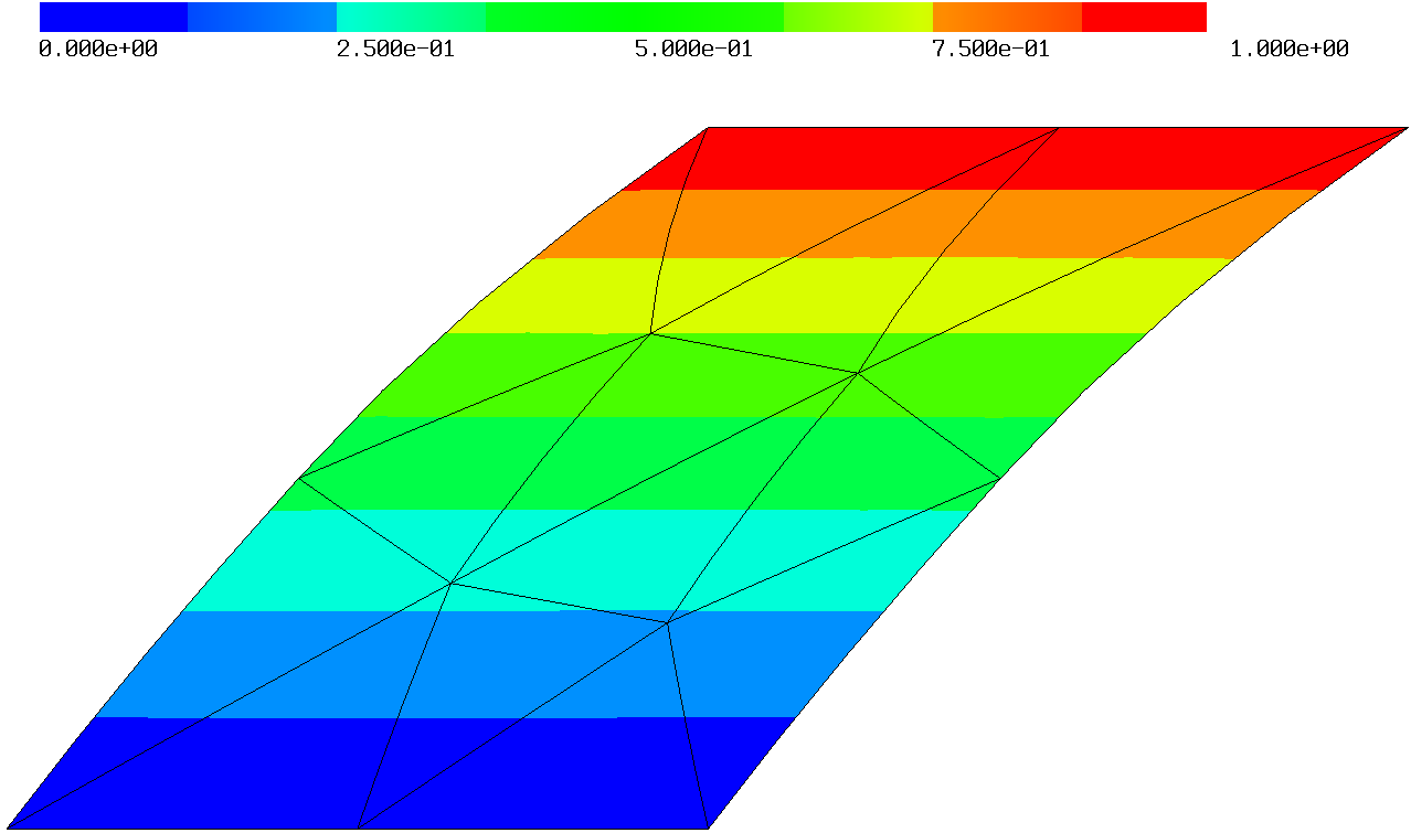
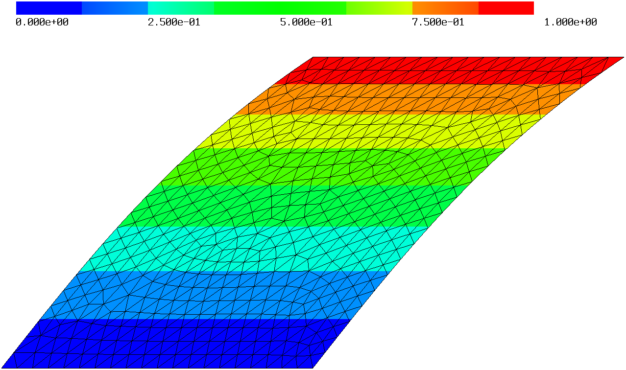


5.2.2 Cook’s Membrane
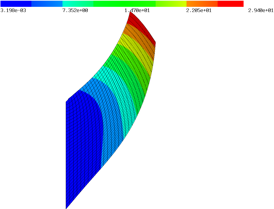
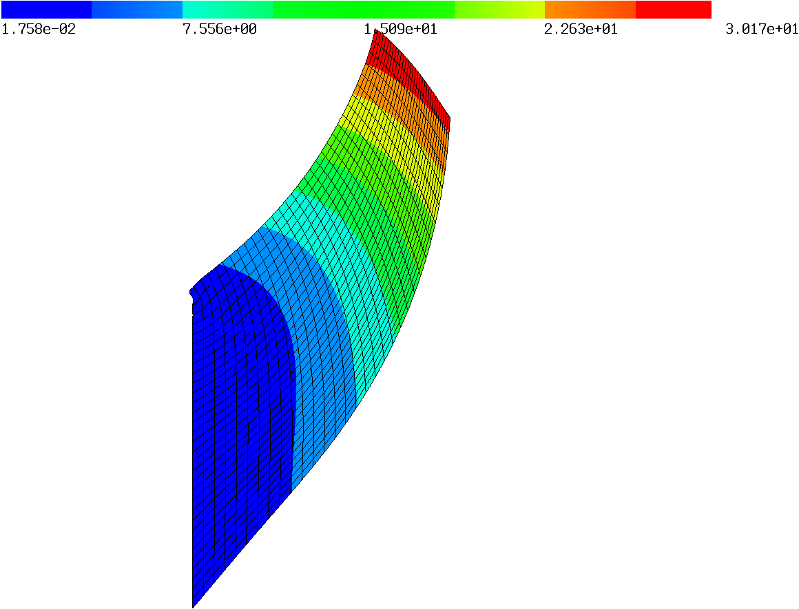
We consider the Cook’s membrane problem, see Figure 5.5, which has been used as a benchmark problem by [1, 33]. Material parameters for the hyperelastic potential (5.2b) are and , which results in nearly incompressible behavior. The quantity of interest is given by the vertical deflection at point , cf. Figure 5.5. Different shear forces are considered and structured quadrilateral meshes with , , , , and grids are used. It is well known that on the top left corner a singularity leads to reduced convergence rates. For this reason mostly adaptive (triangular) meshes are used to resolve the singularity. For the proposed methods, however, already a coarse quadrilateral grid produces surprisingly accurate results being already in the correct magnitude, see Figure 5.6. In Figure 5.7 a comparison between the standard and -based method for is shown, where a clear difference in the vertical deflection can be seen. We observed that the quadrilateral on the top left deforms also on the clamped boundary, as the components are not prescribed point-wise giving the proposed methods more flexibility.


For the -based method stabilization techniques (3.21) and (3.22) are used with parameters . With them, only on the finest grid for the large forces Newton’s method did not converge. The results for all forces can be found in Tables 5.2 – 5.3. All results agree with those in [1, 33].
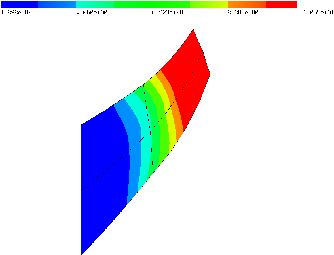
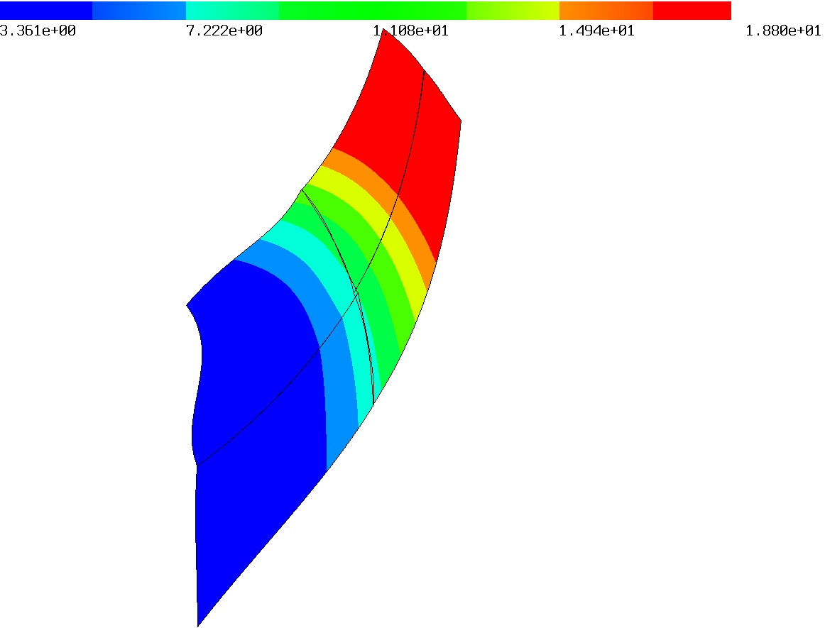
| coupl. dof | w | w | |||
|---|---|---|---|---|---|
| std | 32 | 5.767 | 86.168 | 9.902 | 153.983 |
| 112 | 7.236 | 113.156 | 12.012 | 199.393 | |
| 416 | 7.992 | 128.938 | 13.281 | 232.024 | |
| 1600 | 8.290 | 135.377 | 13.794 | 246.522 | |
| 6272 | 8.403 | 137.821 | 13.977 | 252.014 | |
| 60 | 8.554 | 141.578 | 14.299 | 261.363 | |
| 216 | 8.527 | 140.770 | 14.218 | 259.260 | |
| 816 | 8.514 | 140.441 | 14.188 | 258.691 | |
| 3168 | 8.509 | 140.312 | 14.195 | 259.070 | |
| 12480 | 8.507 | 140.282 | 14.201 | 259.345 | |
| 60 | 8.219 | 134.345 | 13.854 | 248.796 | |
| 216 | 8.377 | 137.746 | 14.026 | 253.700 | |
| 816 | 8.442 | 139.008 | 14.092 | 255.674 | |
| 3168 | 8.474 | 139.567 | 14.122 | 256.684 | |
| 12480 | 8.489 | 139.849 | 14.142 | 257.377 | |
| 60 | 8.553 | 141.513 | 14.295 | 261.013 | |
| 216 | 8.522 | 140.635 | 14.205 | 258.870 | |
| 816 | 8.510 | 140.349 | 14.179 | 258.389 | |
| 3168 | 8.507 | 140.257 | 14.300 | 262.429 | |
| 12480 | 8.506 | 140.244 | 14.204 | 259.429 |
| coupl. dof | w | w | |||
|---|---|---|---|---|---|
| std | 32 | 13.305 | 212.422 | 16.348 | 265.766 |
| 112 | 15.579 | 269.195 | 18.574 | 329.713 | |
| 416 | 17.052 | 315.428 | 20.053 | 385.690 | |
| 1600 | 17.700 | 337.958 | 20.778 | 415.150 | |
| 6272 | 17.948 | 346.933 | 21.093 | 427.745 | |
| 60 | 18.439 | 363.620 | 21.769 | 453.584 | |
| 216 | 18.317 | 359.827 | 21.639 | 448.622 | |
| 816 | 18.317 | 360.305 | 21.747 | 453.602 | |
| 3168 | 18.346 | 361.587 | 21.612 | 448.416 | |
| 12480 | 18.281 | 359.313 | 21.530 | 445.142 | |
| 60 | 17.961 | 345.705 | 21.217 | 429.143 | |
| 216 | 18.103 | 351.545 | 21.348 | 435.983 | |
| 816 | 18.157 | 354.038 | 21.402 | 439.090 | |
| 3168 | 18.188 | 355.592 | 21.453 | 441.644 | |
| 12480 | - | - | - | - | |
| 60 | 18.424 | 362.626 | 21.734 | 451.528 | |
| 216 | 18.292 | 358.944 | 21.596 | 446.903 | |
| 816 | 18.584 | 370.337 | 21.769 | 455.071 | |
| 3168 | 18.345 | 361.562 | 21.573 | 446.896 | |
| 12480 | 18.265 | 358.718 | 21.531 | 445.182 |
5.2.3 Thin Beam
For the thin beam example we follow [33, 51], where the beam is clamped at the left side and a point load at is applied. But instead of a point load we choose a shear force on the right boundary such that the displacement is in the same magnitude, see Figure 5.8. This modification is needed as point-evaluation is not well defined in context of Sobolev spaces and traces, and cannot be set directly in terms of the TDNNS method. There, only the tangential trace is well defined for the displacement and the normal trace for the hybridization variable . The quantity of interest is again the vertical deflection at point . Structured quadrilateral meshes with , , , and grids are used. The material parameters are and and the hyperelastic potential (5.2b) is considered.

We observe that all three methods perform well, even for the coarsest grid. As discussed and shown in [27] the linear TDNNS method is extremely robust for anisotropic elements. The standard Lagrangian method converges also, however, it needs a finer grid to produce accurate solutions, see Table 5.4 and Figure 5.9 for the results.
| coupl. dof | w | coupl. dof | w | |||
|---|---|---|---|---|---|---|
| ne=10 | ne=40 | |||||
| std | 100 | 7.036 | 3.992 | 320 | 7.346 | 4.273 |
| 180 | 7.390 | 4.314 | 600 | 7.399 | 4.321 | |
| 180 | 7.391 | 4.314 | 600 | 7.399 | 4.321 | |
| 180 | 7.390 | 4.314 | 600 | 7.399 | 4.321 | |
| ne=160 | ne=640 | |||||
| std | 1120 | 7.391 | 4.314 | 4160 | 7.402 | 4.324 |
| 2160 | 7.405 | 4.326 | 8160 | 7.407 | 4.329 | |
| 2160 | 7.405 | 4.326 | 8160 | 7.407 | 4.329 | |
| 2160 | 7.405 | 4.326 | 8160 | 7.407 | 4.329 |

5.2.4 Inflation of a Hollow Spherical Ball
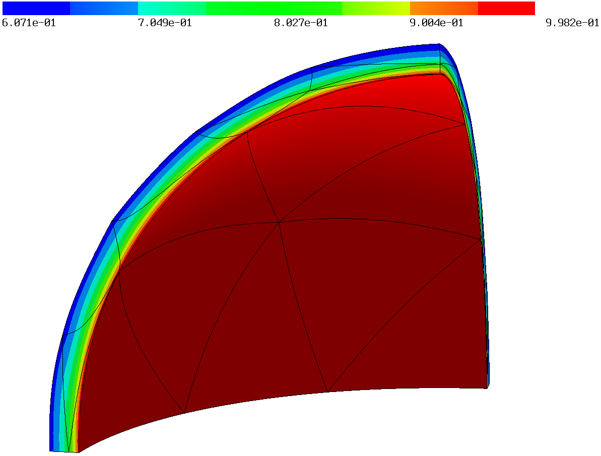
A hollow spherical ball is subjected to the boundary condition on the inner boundary, whereas the outer boundary is left free. The inner and outer radius are given by and , respectively. We adapted the benchmark in [42] by setting the material parameters and together with the hyperelastic potential (5.2b) instead of using a complete incompressible material. This choice of , however, leads to a Poisson ratio and thus, the example is already close to the nearly incompressible regime. The final configuration is reached for , starting from , the initial configuration. Due to symmetry, only one eight of the ball is considered, see Figure 5.10. Unstructured curved tetrahedral meshes are used as shown in Figure 5.11.
We note that the standard method does not converge for polynomial order , whereas the - and -based method do. Thus, only for the Lagrangian elements order is considered. The -based method, however, does not converge - even with the stabilization terms (3.21) and (3.22). Although a higher polynomial order is used, the standard method does not perform as good as the - and -based method for the coarse grid, cf. Figure 5.12. The results are listed in Table 5.5.



| ne | dof | coupl. dof | w | ||
|---|---|---|---|---|---|
| std | 85 | 1578 | 1578 | -0.630 | 0.517 |
| 244 | 4287 | 4287 | -0.620 | 0.517 | |
| 494 | 8322 | 8322 | -0.620 | 0.518 | |
| 2405 | 36528 | 36528 | -0.620 | 0.518 | |
| 85 | 17496 | 2196 | -0.619 | 0.517 | |
| 244 | 50019 | 6099 | -0.620 | 0.517 | |
| 494 | 100983 | 12063 | -0.620 | 0.518 | |
| 2405 | 488073 | 55173 | -0.620 | 0.518 | |
| 85 | 37896 | 2196 | -0.619 | 0.517 | |
| 244 | 108579 | 6099 | -0.620 | 0.517 | |
| 494 | 219543 | 12063 | -0.620 | 0.518 | |
| 2405 | 1065273 | 55173 | -0.620 | 0.518 |
5.2.5 Cylindrical Shell
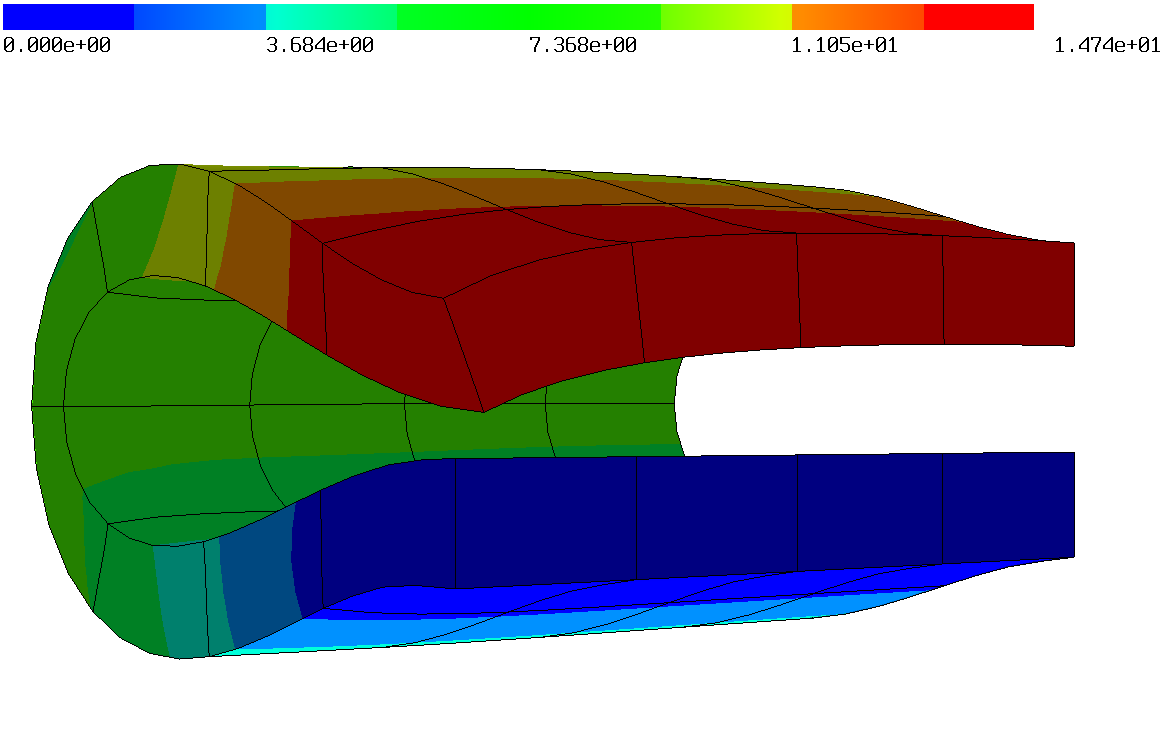
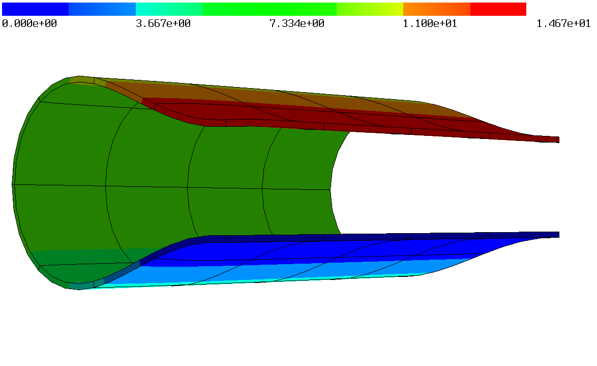
The benchmark presented in [36, 33] is adapted in terms of the force and boundary condition as line forces and traces are not well defined in terms of Sobolev spaces in three spatial dimensions. The same geometry and material parameters are considered. Namely, a quarter of a cylindrical structure with , , and thickness or , see Figure 5.13, and and together with the hyperelastic potential (5.2b). The structure is clamped at the bottom area and an area shear force ( for ) is applied on the top. Structured hexahedra meshes with , , and grids are used, see Figure 5.14. For the standard method also a grid is used. The vertical deflection at point is depicted in Figure 5.16, the final deformations are shown in Figure 5.15, and the results can be found in Table 5.6. We observed a locking behaviour for the standard method, which becomes significant for the small thickness. All of the three presented methods give satisfying results already for the coarsest discretization. The reference values were computed with the standard method and degree on the finest grid, where locking is avoided due to the high polynomial degree. As only one layer in the thin direction is used the methods do not converge towards to reference solution for . For the thin structure, , the values match. As already mentioned the -based method may suffer from a larger number of Newton iterations to reach convergence, whereas the - and -based method have a better convergence behavior. In Table 5.7 the numbers of Newton iterations can be found, where twelve load steps were considered. Also the standard method needs more iterations than the - and -based variant.




| coupl. dof | w | w | |||
|---|---|---|---|---|---|
| std | 1125 | -13.676 | 211.958 | -2.613 | 14.350 |
| 4365 | -14.835 | 231.071 | -10.927 | 58.065 | |
| 17181 | -15.030 | 234.734 | -14.287 | 76.437 | |
| 68157 | -15.067 | 235.513 | -14.806 | 79.387 | |
| 3300 | -15.598 | 244.530 | -14.749 | 78.920 | |
| 12936 | -15.658 | 245.756 | -14.844 | 79.571 | |
| 51216 | -15.678 | 246.149 | -14.876 | 79.825 | |
| 300 | -15.648 | 245.779 | -14.304 | 76.878 | |
| 12936 | -15.721 | 246.883 | -14.830 | 79.521 | |
| 51216 | -15.784 | 247.951 | -14.876 | 79.825 | |
| 3300 | -15.600 | 244.586 | -14.753 | 78.946 | |
| 12936 | -15.658 | 245.757 | -14.844 | 79.576 | |
| 51216 | -15.678 | 246.143 | -14.876 | 79.825 |
| std | ||||
|---|---|---|---|---|
| 6 | 5 | 5 | 5 | |
| 7 | 7-8 | 4-5 | 4-5 |
5.2.6 Thin Beam subjected to end moment
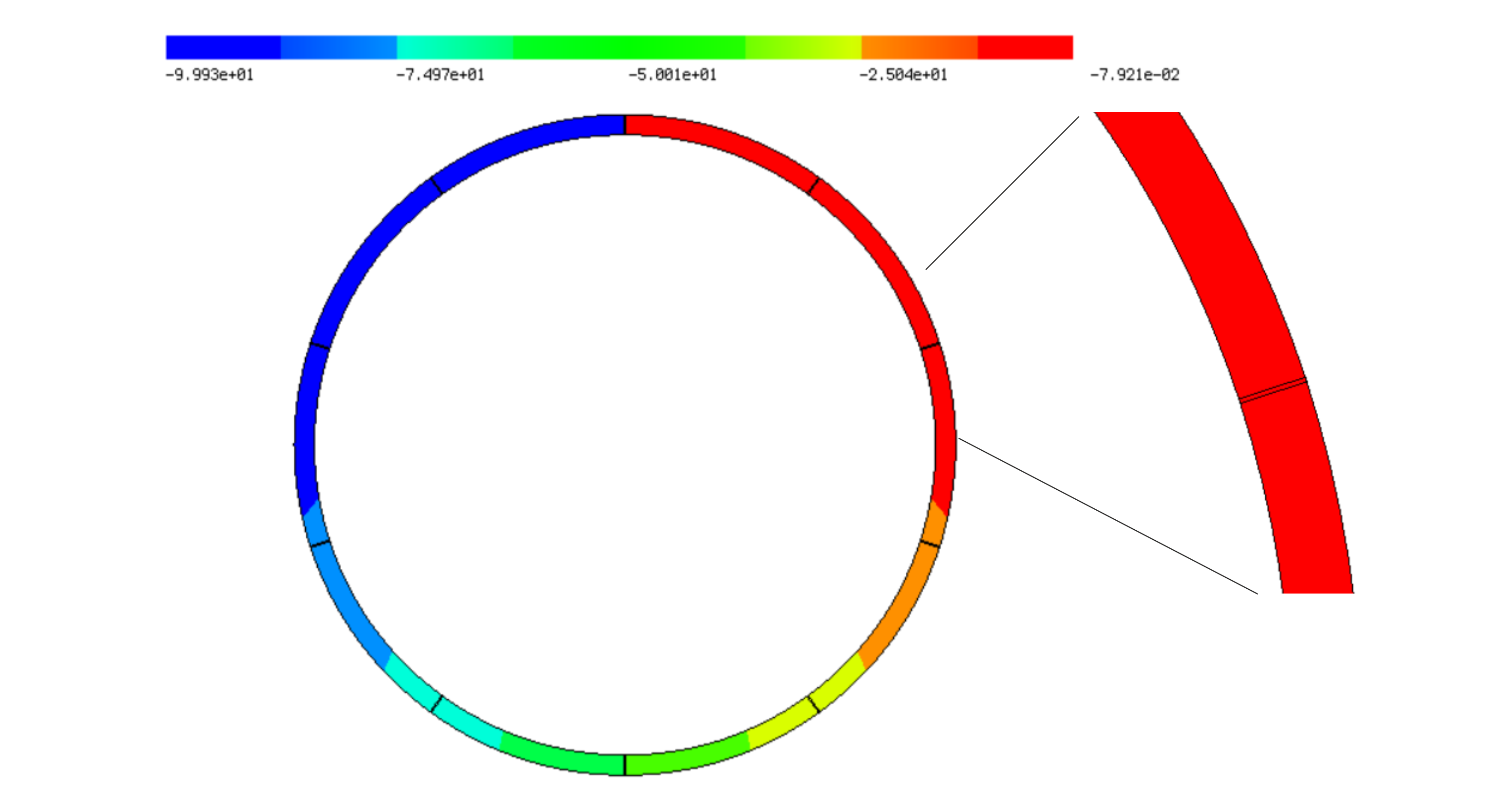
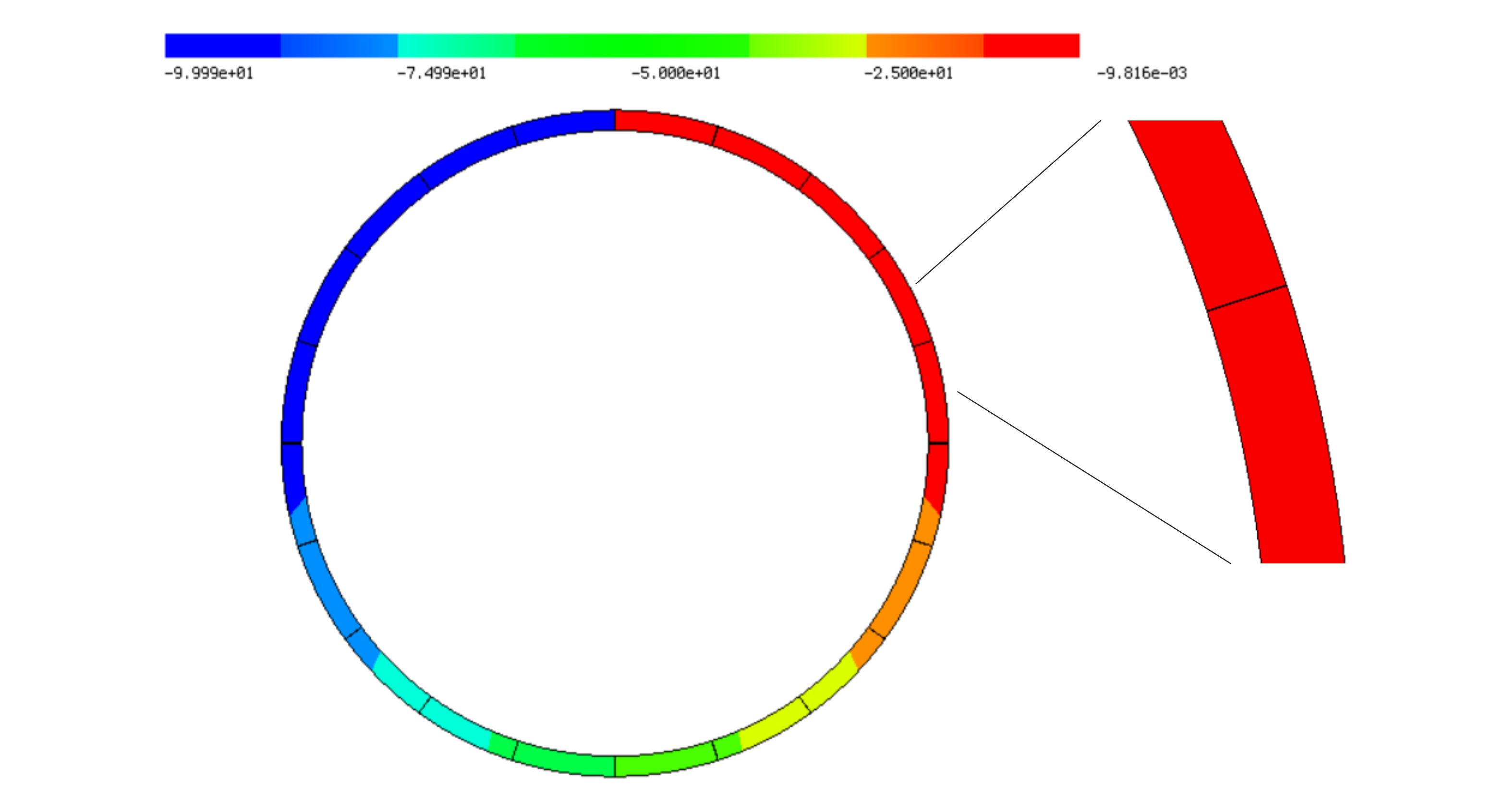
For this example we use a cantilever beam, clamped at the left-hand side, of length and thickness . To allow for an anayltical solution, we choose material parameters and . An end moment is applied such that the beam cross-section rotates by , thereby forming a perfect circle in the theory of thin shells. Due to the enormous deformation the Updated Lagrangian scheme discussed in Section 4 is used for all presented methods. Two different grids are used, where one element is used in thickness direction, and or elements in axial direction. The quantity of interest is given by the applied moment necessary to rotate the cross-section at the tip by . In Figure 5.17 the final deformation is depicted and the results, as well as the absolute and relative error in the necessary moment as compared to the analytical value of are given in Table 5.8. The -based method did not converge for the coarsest grid and elements of order one, whereas the other two methods always converged. The overall accuracy of the methods is comparable. Concerning iteration counts, the - and -based methods converged very fast, needing 3-7 iterations in each of the 12 load steps. In comparison, for the standard nodal FEM and the -based methods, more than 20 iterations were necessary in some of the load steps.
| coupl. dof | moment | rel. error | coupl. dof | moment | rel. error | |
|---|---|---|---|---|---|---|
| ne = 10 | order 1 | order 2 | ||||
| std. method | 40 | 5538.381 | 51.888 | 100 | 231.149 | 1.207314 |
| 120 | 103.172 | -0.014781 | 180 | 104.685 | -0.000330 | |
| 120 | – | – | 180 | 104.744 | 0.000229 | |
| 120 | 101.399 | -0.031715 | 180 | 104.679 | -0.000385 | |
| ne = 20 | order 1 | order 2 | ||||
| std | 80 | 1425.993 | 12.617 | 200 | 113.175 | 0.080743 |
| 240 | 103.908 | -0.007750 | 360 | 104.734 | 0.000138 | |
| 240 | 104.668 | -0.000498 | 360 | 104.738 | 0.000177 | |
| 240 | 103.878 | -0.008038 | 360 | 104.734 | 0.000138 |
Acknowledgements
The support by the Austrian Science Fund (FWF) projects W 1245 and F 65 is gratefully acknowledged.
Appendix A Proof of consistency
We prove consistency of problem (3.16). If we take the variation of (3.17) in direction and look at the left-hand side
we want to recover the strong form if we insert the true, smooth solution . First, the hybridization variable is the normal trace of and thus, on . Integration by parts and reordering yields
| (A.1) |
The first term states the element wise balance equation and the second the continuity of the normal-tangential components of the first Piola–Kirchhoff stress tensor. Reordering hybridization terms in (3.17) yields
| (A.2) |
forcing the normal-normal continuity and thus, the continuity of the normal component of the first Piola–Kirchhoff stress tensor. Hence, also the interface condition is fulfilled and the problem is consistent.
Appendix B Linearization
Computing the first variations and under the assumption of small deformations, i.e., , , , , and , the variations of (3.17) become
| (B.1a) | ||||||
| (B.1b) | ||||||
| (B.1c) | ||||||
| (B.1d) | ||||||
where we implicitly defined and . Assuming a quadratic potential, i.e., , and eliminating by with (B.1a) recovers the hybridized TDNNS method (2.4). Thus, the linearized versions of (3.17) and (3.6) coincide.
References
- [1] Angoshtari, A., Shojaei, M. F., and Yavari, A. Compatible-strain mixed finite element methods for 2D compressible nonlinear elasticity. Computer Methods in Applied Mechanics and Engineering 313 (2017), 596–631.
- [2] Angoshtari, A., and Yavari, A. Hilbert complexes of nonlinear elasticity. Zeitschrift für angewandte Mathematik und Physik 67, 6 (2016), 143.
- [3] Arnold, D., Awanou, G., and Winther, R. Finite elements for symmetric tensors in three dimensions. Mathematics of Computation 77, 263 (2008), 1229–1251.
- [4] Arnold, D., Falk, R., and Winther, R. Mixed finite element methods for linear elasticity with weakly imposed symmetry. Mathematics of Computation 76, 260 (2007), 1699–1723.
- [5] Arnold, D. N., Brezzi, F., and Douglas, J. PEERS: a new mixed finite element for plane elasticity. Japan Journal of Applied Mathematics 1, 2 (1984), 347.
- [6] Arnold, D. N., and Winther, R. Mixed finite elements for elasticity. Numerische Mathematik 92, 3 (2002), 401–419.
- [7] Artioli, E., Da Veiga, L. B., Lovadina, C., and Sacco, E. Arbitrary order 2D virtual elements for polygonal meshes: part II, inelastic problem. Computational Mechanics 60, 4 (2017), 643–657.
- [8] Bayat, H. R., Krämer, J., Wunderlich, L., Wulfinghoff, S., Reese, S., Wohlmuth, B., and Wieners, C. Numerical evaluation of discontinuous and nonconforming finite element methods in nonlinear solid mechanics. Computational Mechanics 62, 6 (2018), 1413–1427.
- [9] Beirão da Veiga, L., Lovadina, C., and Mora, D. A virtual element method for elastic and inelastic problems on polytope meshes. Computer Methods in Applied Mechanics and Engineering 295 (2015), 327–346.
- [10] Boffi, D., Brezzi, F., and Fortin, M. Mixed finite element methods and applications, vol. 44. Springer, Berlin, Heidelberg, 2013.
- [11] Bonet, J., Gil, A. J., and Ortigosa, R. A computational framework for polyconvex large strain elasticity. Computer Methods in Applied Mechanics and Engineering 283 (2015), 1061–1094.
- [12] Bonet, J., Gil, A. J., and Ortigosa, R. On a tensor cross product based formulation of large strain solid mechanics. International Journal of Solids and Structures 84 (2016), 49–63.
- [13] Braess, D. Finite elements: Theory, fast solvers, and applications in elasticity theory, 3 ed. Cambridge University Press, 2007.
- [14] Brezzi, F., Douglas, J., and Marini, L. D. Two families of mixed finite elements for second order elliptic problems. Numerische Mathematik 47, 2 (1985), 217–235.
- [15] Cheeger, J., Müller, W., and Schrader, R. Kinematic and tube formulas for piecewise linear spaces. Indiana University Mathematics Journal 35, 4 (1986), 737–754.
- [16] Chi, H., da Veiga, L. B., and Paulino, G. Some basic formulations of the virtual element method (VEM) for finite deformations. Computer Methods in Applied Mechanics and Engineering 318 (2017), 148–192.
- [17] Christiansen, S. H. On the linearization of Regge calculus. Numerische Mathematik 119, 4 (2011), 613–640.
- [18] Cockburn, B., Gopalakrishnan, J., and Lazarov, R. Unified hybridization of discontinuous Galerkin, mixed, and continuous Galerkin methods for second order elliptic problems. SIAM Journal on Numerical Analysis 47, 2 (2009), 1319–1365.
- [19] Kasper, E. P., and Taylor, R. L. A mixed-enhanced strain method: Part I: Geometrically linear problems. Computers & Structures 75, 3 (2000), 237–250.
- [20] Kasper, E. P., and Taylor, R. L. A mixed-enhanced strain method: Part II: Geometrically nonlinear problems. Computers & Structures 75, 3 (2000), 251–260.
- [21] Li, L. Regge Finite Elements with Applications in Solid Mechanics and Relativity. PhD thesis, University of Minnesota, 2018.
- [22] Meindlhumer, M., and Pechstein, A. 3D mixed finite elements for curved, flat piezoelectric structures. International Journal of Smart and Nano Materials 10, 4 (2019), 249–267.
- [23] Monk, P. Finite element methods for Maxwell’s equations. Numerical Mathematics and Scientific Computation. Oxford University Press, New York, 2003.
- [24] Nédélec, J. C. A new family of mixed finite elements in R3. Numerische Mathematik 50, 1 (1986), 57–81.
- [25] Neunteufel, M. Mixed Finite Element Methods for Nonlinear Continuum Mechanics and Shells. PhD thesis, TU Wien, 2021.
- [26] Pechstein, A., and Schöberl, J. Tangential-displacement and normal-normal-stress continuous mixed finite elements for elasticity. Mathematical Models and Methods in Applied Sciences 21, 8 (2011), 1761–1782.
- [27] Pechstein, A., and Schöberl, J. Anisotropic mixed finite elements for elasticity. International Journal for Numerical Methods in Engineering 90, 2 (2012), 196–217.
- [28] Pechstein, A., and Schöberl, J. An analysis of the TDNNS method using natural norms. Numerische Mathematik 139, 1 (2018), 93–120.
- [29] Pechstein, A. S. Large deformation mixed finite elements for smart structures. Mechanics of Advanced Materials and Structures 0, 0 (2019), 1–11.
- [30] Pfefferkorn, R., and Betsch, P. Extension of the enhanced assumed strain method based on the structure of polyconvex strain-energy functions. International Journal for Numerical Methods in Engineering 121, 8 (2020), 1695–1737.
- [31] Raviart, P.-A., and Thomas, J.-M. A mixed finite element method for 2-nd order elliptic problems. In Mathematical Aspects of Finite Element Methods, vol. 66. Springer, 1977, pp. 292–315.
- [32] Reddy, B. D., and Simo, J. C. Stability and convergence of a class of enhanced strain methods. SIAM Journal on Numerical Analysis 32, 6 (1995), 1705–1728.
- [33] Reese, S. On the equivalent of mixed element formulations and the concept of reduced integration in large deformation problems. International Journal of Nonlinear Sciences and Numerical Simulation 3, 1 (2002), 1–34.
- [34] Reese, S. A large deformation solid-shell concept based on reduced integration with hourglass stabilization. International Journal for Numerical Methods in Engineering 69, 8 (2007), 1671–1716.
- [35] Reese, S., Bayat, H. R., and Wulfinghoff, S. On an equivalence between a discontinuous Galerkin method and reduced integration with hourglass stabilization for finite elasticity. Computer Methods in Applied Mechanics and Engineering 325 (2017), 175–197.
- [36] Reese, S., Wriggers, P., and Reddy, B. D. A new locking-free brick element technique for large deformation problems in elasticity. Computers & Structures 75, 3 (2000), 291–304.
- [37] Regge, T. General relativity without coordinates. Il Nuovo Cimento (1955-1965) 19, 3 (1961), 558–571.
- [38] Schöberl, J. NETGEN an advancing front 2D/3D-mesh generator based on abstract rules. Computing and Visualization in Science 1, 1 (1997), 41–52.
- [39] Schöberl, J. C++ 11 implementation of finite elements in NGSolve. Institute for Analysis and Scientific Computing, Vienna University of Technology (2014).
- [40] Schröder, J., Wriggers, P., and Balzani, D. A new mixed finite element based on different approximations of the minors of deformation tensors. Computer Methods in Applied Mechanics and Engineering 200, 49 (2011), 3583–3600.
- [41] Shojaei, M. F., and Yavari, A. Compatible-strain mixed finite element methods for incompressible nonlinear elasticity. Journal of Computational Physics 361 (2018), 247–279.
- [42] Shojaei, M. F., and Yavari, A. Compatible-strain mixed finite element methods for 3D compressible and incompressible nonlinear elasticity. Computer Methods in Applied Mechanics and Engineering 357 (2019), 112610.
- [43] Simo, J. C., and Armero, F. Geometrically non-linear enhanced strain mixed methods and the method of incompatible modes. International Journal for Numerical Methods in Engineering 33, 7 (1992), 1413–1449.
- [44] Simo, J. C., Armero, F., and Taylor, R. L. Improved versions of assumed enhanced strain tri-linear elements for 3D finite deformation problems. Computer Methods in Applied Mechanics and Engineering 110, 3 (1993), 359–386.
- [45] Simo, J. C., and Rifai, M. S. A class of mixed assumed strain methods and the method of incompatible modes. International Journal for Numerical Methods in Engineering 29, 8 (1990), 1595–1638.
- [46] Simo, J. C., Taylor, R. L., and Pister, K. S. Variational and projection methods for the volume constraint in finite deformation elasto-plasticity. Computer Methods in Applied Mechanics and Engineering 51, 1 (1985), 177–208.
- [47] Sinwel, A. A New Family of Mixed Finite Elements for Elasticity. PhD thesis, Johannes Kepler University Linz, 2009.
- [48] Stenberg, R. A family of mixed finite elements for the elasticity problem. Numerische Mathematik 53, 5 (1988), 513–538.
- [49] Washizu, K. Variational methods in elasticity and plasticity, vol. 3. Pergamon press Oxford, 1975.
- [50] Wriggers, P., Reddy, B. D., Rust, W., and Hudobivnik, B. Efficient virtual element formulations for compressible and incompressible finite deformations. Computational Mechanics 60, 2 (2017), 253–268.
- [51] Wulfinghoff, S., Bayat, H. R., Alipour, A., and Reese, S. A low-order locking-free hybrid discontinuous Galerkin element formulation for large deformations. Computer Methods in Applied Mechanics and Engineering 323 (2017), 353–372.
- [52] Zaglmayr, S. High Order Finite Element Methods for Electromagnetic Field Computation. PhD thesis, Johannes Kepler Universität Linz, 2006.
- [53] Zienkiewicz, O., and Taylor, R. The Finite Element Method. Vol. 1: The Basis, 5 ed. Butterworth-Heinemann, 2000.