Domain Decomposition Parabolic Monge-Ampère Approach for Fast Generation of Adaptive Moving Meshes
Abstract
A fast method is presented for adaptive moving mesh generation in multi-dimensions using a domain decomposition parabolic Monge-Ampère approach. The domain decomposition procedure employed here is non-iterative and involves splitting the computational domain into overlapping subdomains. An adaptive mesh on each subdomain is then computed as the image of the solution of the optimal mass transfer problem using a parabolic Monge-Ampère method. The domain decomposition approach allows straightforward implementation for the parallel computation of adaptive meshes which helps to reduce computational time significantly. Results are presented to show the numerical convergence of the domain decomposition solution to the single domain solution. Several numerical experiments are given to demonstrate the performance and efficiency of the proposed method. The numerical results indicate that the domain decomposition parabolic Monge-Ampère method is more efficient than the standard implementation of the parabolic Monge-Ampère method on the whole domain, in particular when computing adaptive meshes in three spatial dimensions.
keywords:
Adaptive mesh , parabolic Monge-Ampère equation , domain decomposition , overlapping domain , parallel computing.MSC:
[2020] 65M50 , 65M061 Introduction
Adaptive mesh methods have become increasingly popular over the last three decades. The use of a uniform grid for solving partial differential equations (PDEs) can be prohibitively expensive, especially for problems in multi-dimensions where their solutions develop sharp structures in some small regions of the physical domain. The large errors in the approximation of the physical solution are expected to occur in those regions. Therefore, mesh adaptation is needed to improve the accuracy of the numerical solution while reducing the computational cost; e.g. see [1, 2, 3, 4]. Numerous adaptive mesh techniques have been developed over the last three decades (see, for example, [5, 6, 7, 8, 9, 10, 11, 12, 13, 14, 15, 16]). Here, we consider a class of adaptive mesh methods called the -refinement or moving mesh method. In this approach the mesh points are continuously redistributed so that they are concentrated in the regions of large solution variations or gradients. In one spatial dimension, the adaptive mesh can be computed based on the equidistribution principle [17, 18]; an estimate of the numerical approximation error is evenly distributed among mesh elements. The equidistribution condition alone is insufficient to uniquely determine an adaptive mesh in multi-dimensions. A number of adaptive moving mesh methods have been developed so far; for example, see [4, 19, 20] and references therein. In this work we are interested in methods based on solving the optimal mass transfer problem [21, 22, 23]. The optimal mass transfer problem, also known as the Monge-Kantorovich problem (MKP), appears in numerous applications in science and engineering [24, 25, 26]. Sulman et al. [22, 27] describe finding the optimal solution of the MKP as the steady state solution of a parabolic Monge-Ampère equation (PMA).
In this paper, we present a domain decomposition parabolic Monge-Ampère (DDPMA) moving mesh method for the generation of adaptive meshes in multi-dimensions. There are two main advantages of domain decomposition approaches for solving PDEs. First, DD is a natural approach for computing the numerical solutions of both steady-state and time-dependent PDEs in parallel. Second, DD allows the use of different time steps on different subdomains in the time dependent context. These ideas can significantly reduce the computational time for adaptive mesh generation. In one dimension DD has been studied theoretically for mesh generation based on the equidistribution principle at the continuous level in [28] and at the discrete level in [29]. Numerical DD methods for PDE based mesh generation in multi-dimensions can also be found in [30, 31]. A recent summary is available in [32]. Our approach here is based on solving the time dependent PMA equation. There are three common approaches used to apply domain decomposition to parabolic problems. The first approach is to apply the traditional iterative Schwarz algorithms first developed for elliptic problems [33, 34, 35, 36, 37, 38] to the elliptic equations which arise upon semi-discretizing the time-dependent PDE in time (see [39, 40, 41, 42, 43, 44, 45]). The second approach is to split the whole space-time domain into overlapping or non-overlapping space-time subdomains in a Schwarz waveform relaxation framework [34, 46, 47, 48]. The third approach is non-iterative domain decomposition which is used to further reduce the computational cost [49, 50, 51, 52, 53, 54]. Motivated by this literature, the DDPMA method proceeds by splitting the computational domain block-wise or slab-wise into overlapping subdomains and computes an approximation to the solution of the MA equation using a non-iterative DD approach at each time level of the pseudo time integration of the nonlinear parabolic Monge-Ampère equation. We will study if this can be done without sacrificing mesh quality.
The paper is organized as follows. In Section 2, we give a brief description of the parabolic Monge-Ampère method for generating adaptive meshes in multi-dimensions based on solving the optimal mass transfer problem. In Section 3, we describe the domain decomposition parabolic Monge-Ampère moving mesh method. In Section 4, several numerical experiments are presented to demonstrate the performance and efficiency of the proposed DDPMA method including results on the numerical convergence of the method. Lastly, a discussion of the results and some concluding remarks are given in Section 5.
2 The parabolic Monge-Ampère adaptive mesh method
The parabolic Monge-Ampère (PMA) method computes an adaptive mesh at any time as the image of a coordinate transformation defined from the logical or computational domain () to the physical domain . The transformation is determined by equidistributing a measure of the solution error or variation over mesh elements in the physical domain [2, 4, 17, 22]. The equidistribution of can be expressed [12, 17] by the constraint
| (1) |
where J is the Jacobian of the transformation. In two spatial dimensions, we have , , and .
Notice that here, we require that the mesh density function to be normalized, i.e. and in this case the right hand side of (1) will be modified to Thus, the constraint (1) takes the form
| (2) |
The equidistribution constraint (2) alone is insufficient to uniquely determine the coordinate transformation, in multi-dimensions. If the solution of the physical model does not involve large variations in the physical domain, then the spatial derivatives of physical solutions can be accurately approximated using standard finite difference schemes on a uniform grid. In this case the coordinate transformation corresponds to the identity map, and the constraint (2) gives . This suggests that we should seek for a coordinate transformation for adaptive mesh generation that is as close to the identity map as possible. Here, we determine the coordinate transformation as the minimizer of the cost functional [26]
| (3) |
subject to the constraint (2). From [26], we find that the minimizer of the cost in (3) is the optimal solution of the optimal mass transfer problem or Monge-Kantorovich problem (MKP).
In [55, 56], it is shown that for bounded positive density function and convex domains and , the solution of the MKP is unique and can be expressed as the gradient of some convex potential ,
| (4) |
where is the gradient operator with respect to the computational variable . Substituting (4) into (2) we obtain the Monge-Ampère equation (MAE)
| (5) |
where is the determinant of the Hessian of .
As in [22, 27], we compute the solution of (5) as the steady-state solution of the parabolic Monge-Ampère equation (PMA)
| (6) |
with the initial and boundary conditions defined as
| (7) |
and
| (8) |
where is the boundary of and is the outward unit normal to . The boundary condition (8) forces mesh points to stay on the boundary of the domain; they can only move along the boundary.
We would like to point out that if the solution of the physical model is time dependent, the initial condition (7) is employed only for computing the initial adaptive mesh. At the subsequent physical time levels, the pseudo time integration of (6) starts at with the initial solution taken as the steady-state solution obtained from the previous physical time level.
The convergence of the solution of (6)–(8) to the steady-state solution and the uniqueness of the latter are shown in [27].
Let be the steady-state solution of (6), (7), and (8), then the adaptive mesh is determined by taking the gradient of , i.e.
| (9) |
To identify the steady-state solution of (6), we use the following stopping criterion:
| (10) |
where TOL is the user specified tolerance.
We remark that the above procedure can be used to generate an adaptive mesh for given analytical functions and steady-state and time-dependent problems. To generate an adaptive mesh for a given function, starting from an initial mesh, the monitor function is computed using the function value at the current mesh and then the new mesh is generated by solving (6) and (8), starting from the current mesh, until the steady state is reached. To generate an adaptive mesh for a steady-state problem, the procedure is similar except that in the current situation, the monitor function is calculated using the computed solution on the current mesh and the physical model needs to be re-solved on the new mesh for the new computed solution. For a time-dependent problem, the monitor function is calculated based on the computed solution and the mesh at the current time step and, after the new mesh is obtained, the physical model is integrated over one time step using the old and new meshes (see, for example, [4]).
3 The domain decomposition moving mesh method
In this section, we describe a DD moving mesh method. Motivated by the Schwarz methods, we describe an overlapping domain decomposition technique for two dimensional domains. The technique can be employed for domains in three spatial dimensions in an analogous way. For simplicity, we consider the computational domain , and spilt into subdomains in one direction (i.e., either in or direction) or in two dimensions (i.e., in both and directions). The subdomains are obtained by the slab or block decompositions, respectively.
A slab decomposition in the direction (the other slab or block decompositions are obtained in a similar manner) is obtained by decomposing the -interval into subintervals in the direction, for , where and . The subdomains are required to overlap in the following manner:
We then have subdomains for in .
For illustration purposes, we consider the case , and divide into two subdomains and , as in Figure 1. Let and be the solution of the Monge-Ampère equation (5) and the corresponding coordinate transformation on the subdomain for In this case, the DDPMA method computes and by solving the two coupled initial value problems (IVPs):
| (11a) | |||
| (11b) | |||
| (11c) | |||
| (11d) | |||
and
| (12a) | |||
| (12b) | |||
| (12c) | |||
| (12d) | |||

We use standard centered finite differences for the spatial discretization of the parabolic Monge-Ampère equations (11a) and (12a) to obtain the IVPs
| (13a) | |||
| (13b) | |||
| (13c) | |||
| (13d) | |||
and
| (14a) | |||
| (14b) | |||
| (14c) | |||
| (14d) | |||
where and are the corresponding finite difference operators for the gradient and Hessian respectively.
Notice that IVPs (13) and (14) are coupled through (13c) and (14c). They can be solved alternately or in parallel for the steady state solutions to obtain and , respectively. The coordinate transformations (and thus adaptive meshes) in and are then determined by setting and , respectively.
For the computation of the steady state solutions, we use an explicit variable time stepping time integrator for the IVPs (13) and (14) over small intervals of time . In our computation we use Matlab function, ode113, a variable-step, variable-order Adams-Bashforth-Moulton PECE solver of orders 1 to 13 for this purpose. Let and be the solutions at time . Let and be the corresponding adaptive meshes at time . We summarize the steps for computing and together with the adaptive meshes and alternately in and in Algorithm 1.
- 1.
-
2.
Compute the adaptive mesh by setting .
-
3.
Compute on and integrate (14) for one time step using the transmission condition
(16) to obtain on .
-
4.
Compute the adaptive mesh by setting .
-
5.
Compute and .
-
6.
Stop if ; Otherwise, set and go to 1.
Notice that here we assume that is small enough so that the same mesh density function can be used for the time integration over the interval .
In the special case of and using slab decompositions, the boundary conditions (11b) and (12b) can be expressed as
| (17) |
and
| (18) |
In this case, the transmission conditions (15) and (16) (defined on the internal boundaries) take the form
| (19) |
and
| (20) |
A parallel DDPMA method is obtained by replacing (20) by
| (21) |
Notice that this is a non-iterative domain decomposition algorithm - there is only one transfer of a subdomain solution information to its neighbouring subdomains per pseudo time step.
4 Numerical experiments
In this section, we present several numerical experiments to demonstrate the performance of the DDPMA method described in Section 3. We have used the DDPMA method with the alternating form of the transmission conditions (19) and (20) for serial computation and with the non-alternating form (21) for parallel computation. We also give some numerical results on the convergence for the method.
For the purpose of conducting these numerical experiments, we choose the mesh density function as the popular arc-length function
| (22) |
where the solution of the physical model and is the gradient operator with respect to .
All the computations in Subsections 4.1 and 4.2 have been done in double precision Matlab on a mac computer with 2.3 GHz Intel Core i7 processor and 16 GB memory.
4.1 A two-dimensional four subdomain decomposition
In this subsection, we present the results of the DDPMA method for computing adaptive meshes in two spatial dimensions. The adaptive mesh is computed with a 4-slab decomposition and block decomposition, i.e. 4 subdomains in both cases. The subdomains are overlapping with an overlap of three grid points in both the slab and block decomposition cases. Notice that for the block decomposition, the overlap occurs in both the -direction and -direction. The alternating DDPMA method described by Algorithem 1 is used for this example.
We consider two different examples of the physical model. For these two examples, we assume the physical and computational domains are and use a grid of size in the whole domain to generate adaptive meshes in the physical domain . The Matlab ODE solver, ode113, is used to integrate the ODE systems (13) and (14) over each time interval for . We have conducted a preliminary comparison with other ODE solvers and time steps and found that this choice of the ODE solver and time step gives better efficiency.
In the first example, we employ the DDPMA method to compute the adaptive mesh for the given function
| (23) |
which is an exact solution for the 2D Burgers’ equation. We take .
In the second example, we consider computing the adaptive mesh for the function
| (24) |
where
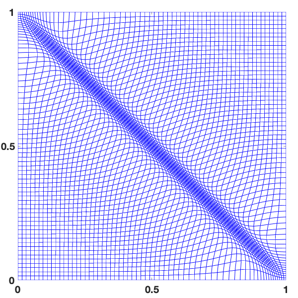
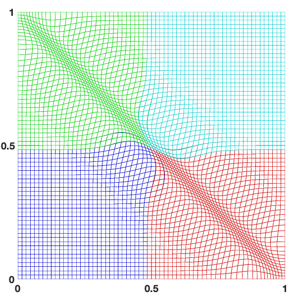
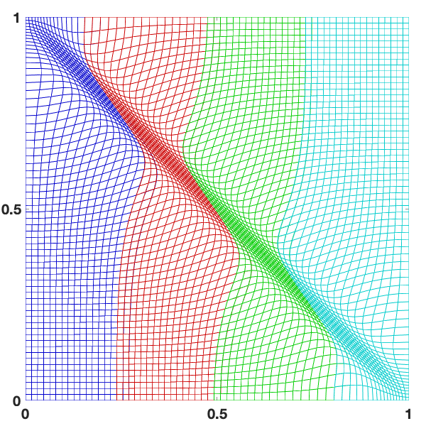
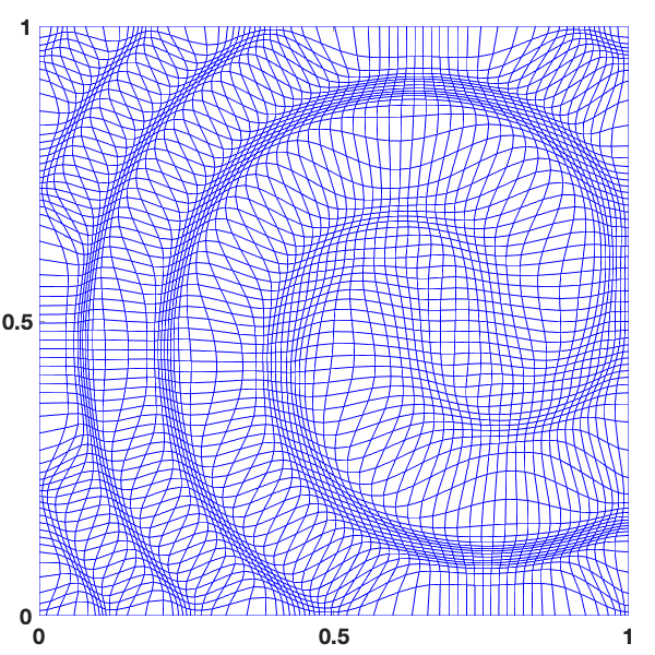
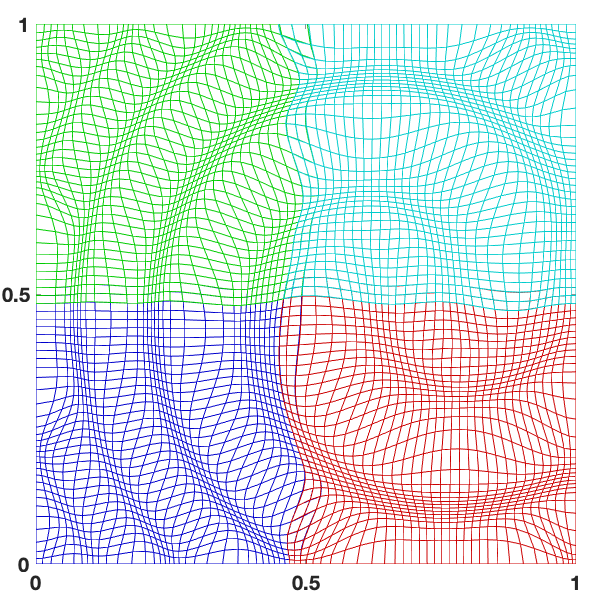
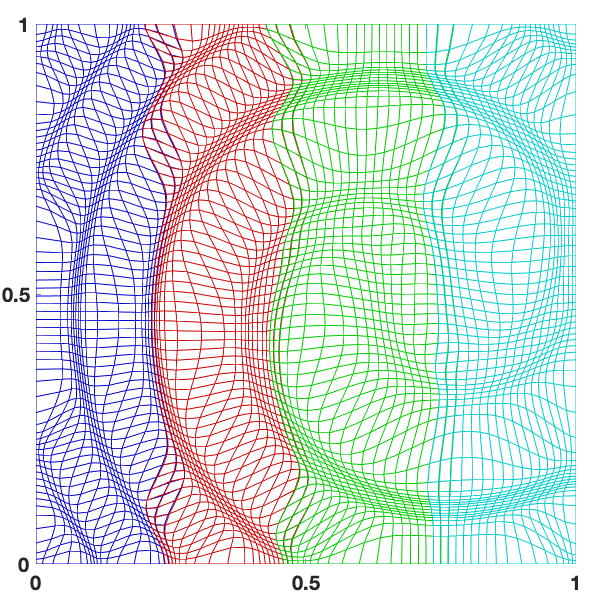
Notice that the Burgers’ solution (23) attains its maximum gradient along the line , i.e. on the diagonal of the physical domain. Test function (24) has its maximum gradient along spiral shape that fills the whole physical domain. As a result, the computed adaptive meshes are expected to concentrate along the line and the spiral shape, respectively.
In Figure 2 (for function (23)) and Figure 3 (for function (24)) we present the adaptive meshes computed on a single domain and using a 4-block and 4-slab decomposition. The figures show that there are no visible differences among the adaptive meshes computed by the PMA method employed on the whole domain and the DDPMA method using 4-slab and 4-block decompositions.
4.2 A three-dimensional eight subdomain decomposition
In this subsection, we illustrate the performance of the DDPMA method for computing adaptive meshes in three spatial dimensions. We consider two different physical model solutions, and employ the DDPMA method to compute the adaptive mesh in the physical domain. Similar to the 2D case, here the alternating DDPMA method with the transmission conditions (15) and (16) is implemented. We use a 8-block decomposition of the computational domain for both examples.
In the first example we assume that the physical solution is given as
| (25) |
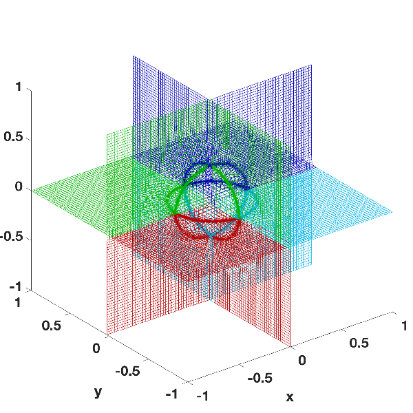
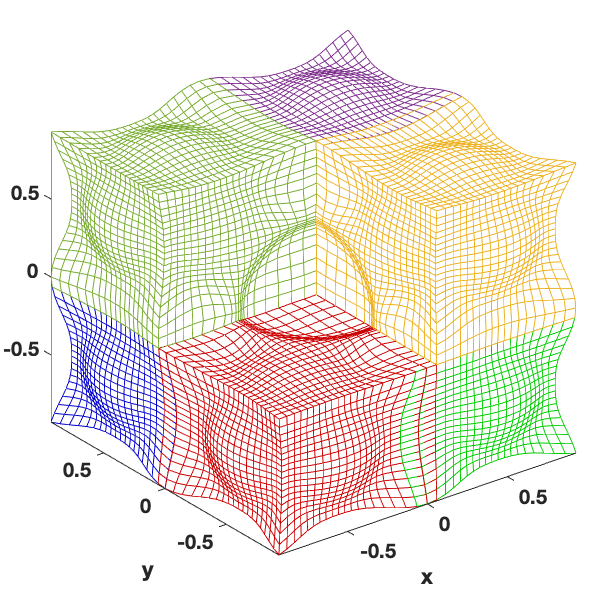
The solution achieves its maximum gradient on the surface of a sphere centered at the origin with radius Thus, the adaptive mesh is expected to be concentrated around the surface of the sphere.
In Figure 4 we show the adaptive meshes computed using the DDPMA method on three planes. The computed mesh appears to concentrate around a circle on each of the planes. This illustrates that the computed mesh is concentrated around the surface of the sphere as expected. We compare the adaptive mesh computed in each block with the mesh computed by applying the PMA method on the whole domain, and we find excellent visual agreement between the two meshes which suggests convergence of the adaptive mesh obtained by the DDPMA method with four subdomains to the adaptive mesh obtained by the PMA method employed on a single domain. The CPU time for the alternating DDPMA method using 8 block is 274 seconds whereas it is 322 seconds for the PMA applied on the whole domain with a grid of size
For the second example, we employ the DDPMA method to compute the adaptive mesh for a test function that exhibits sharp structures that fill the whole physical domain. To this end, let and assume that the solution of the physical model is given as
| (26) |
where
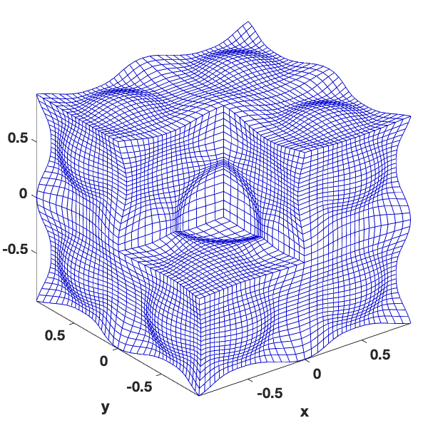
The test function (26) has its maximum gradients on the surfaces of nine spheres that are of radius and centered at , in the physical domain. The adaptive mesh is expected to be clustered around the surfaces of the nine spheres. Figure 5 presents adaptive meshes computed on a single domain and using an 8-block decomposition. The concentration of the adaptive mesh can be seen along the surfaces of the nine spheres. The figure also shows a very good agreement of the adaptive mesh obtained by DDPMA method using 8-block decomposition and the adaptive mesh obtained by the PMA method employed on the whole domain.
4.3 Efficiency of the DDPMA method
We demonstrate the efficiency of the DDPMA method by examining the CPU time for the DDPMA method using four subdomains in 2D and eight subdomains in 3D. We compare the results of the DDPMA method with the PMA method employed on the entire domain. To this end, we compute the adaptive meshes for different grid resolutions in both two and three spatial dimensions. The DDPMA method is employed for both serial and parallel computations. For the parallel algorithm, the time integration of the ODE systems (13) and (14) from time level to on the subdomains is carried out in parallel using four processors for the case of 4 subdomains and 8 processors for the case of 8 subdomains.
The computations in this subsection are conducted using double precision Matlab on a mac computer with 3.3 GHz 12-core Intel Xeon W processor and 32 GB memory.
In Table 1 we present the CPU time required to compute the 2D adaptive meshes for the test function (24) using the grid resolutions , , , and . We can see that for two dimensional problems, the DDPMA method becomes more efficient (in terms of the CPU time relative to the time required for the single domain solution) as the number of the grid points increase.
Table 2 shows the CPU time to compute 3D adaptive meshes for the test function (25) using the grid resolutions , , and From these results it becomes clear that the DDPMA method is more efficient than the PMA method employed on the entire domain. The results presented here indicate that employing the DDPMA method in parallel improves the computational time significantly. We would like to point out that one can employ the DDPMA method in parallel with more subdomains and processors as needed to further speed up the computations.
| grid size | CPU time in seconds | ||
|---|---|---|---|
| single domain | 4-block subdomains | ||
| serial | parallel (4-core) | ||
| 0.2 | 0.31 | 0.53 | |
| 0.38 | 0.51 | 0.66 | |
| 0.8 | 1 | .76 | |
| 3.53 | 2.7 | 1.6 | |
| 13.51 | 10.94 | 7.09 | |
| grid size | CPU time in seconds | ||
|---|---|---|---|
| single domain | 8-block subdomains | ||
| serial | parallel (8-core) | ||
| 20 | 18 | 4 | |
| 30 | 29 | 8 | |
| 62 | 58 | 16 | |
| 104 | 94 | 37 | |
4.4 Convergence of the DDPMA method
In this subsection, we study the numerical convergence of the DDPMA method in two spatial dimensions. We study the convergence of the solution obtained by the DDPMA method using the four-subdomain decomposition to the solution obtained by the PMA method on a single domain.
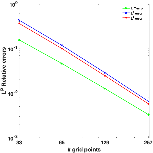
The analytical solution of the parabolic Monge-Ampère equation (6) is not available, therefore we use a solution computed by the PMA method on the single domain with a very fine grid resolution and for a very large number of pseudo time steps as a surrogate for the exact solution. Specifically, we consider the test function (24) and employ the PMA method to compute the solution of the parabolic Monge-Ampère equation (6) with a grid of size and 10000 pseudo time steps. This gives a solution that we assume is close enough to the exact solution. Then, we employ the DDPMA method with 4 subdomains to solve (6) using the grid resolutions , , and and 1000 pseudo time steps to obtain a combined solution, , on the union of the four subdomains. The relative error is computed as
| (27) |
for . The relative error is obtained as
| (28) |
Figure 6 presents the plots of the relative errors for , 2, and in the logarithmic scale. The slopes of the , , and errors are 1.85, 2.01 and 1.99, respectively, which suggests that the convergence of the DDPMA method is second order in space.
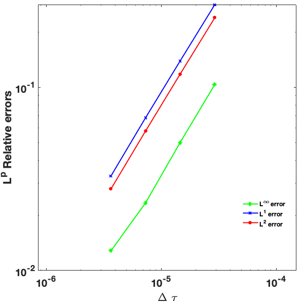
To examine the convergence rate in the pseudo time variable. For the purpose of this test, we use the forward Euler method for the time integration of the ODE systems (13) and (14). To this end, we fix the grid size to for whole domain and solve the parabolic Monge-Ampère equation (6) using small pseudo time step and 5000 pseudo time steps to obtain the solution . Then, we employ the DDPMA method with four subdomains using same grid resolution but different pseudo time steps , , , and to obtain for each pseudo time step size . We can then use the formulas (27) and (28) to compute the relative errors for , 2, and . In Figure 7, we show the relative errors in the logarithmic scale. For this test only, we use a forward Euler integrator in time, instead of the variable time stepping, variable order, ode113. We find that the slopes of these relative errors are 1.01, 1.04 and 1.03, respectively. This illustrates that the convergence of the DDPMA method is first order in time.
We now study the convergence history of the domain decomposition solution as the number of time steps increases for a fixed mesh resolution and a fixed . We take the steady-state single-domain solution of the same spatial resolution as the reference solution. Figure 8 shows the convergence history of the solution of the domain decomposition method to the single domain solution. It shows that the former converges to the latter as the number of pseudo time steps increases.
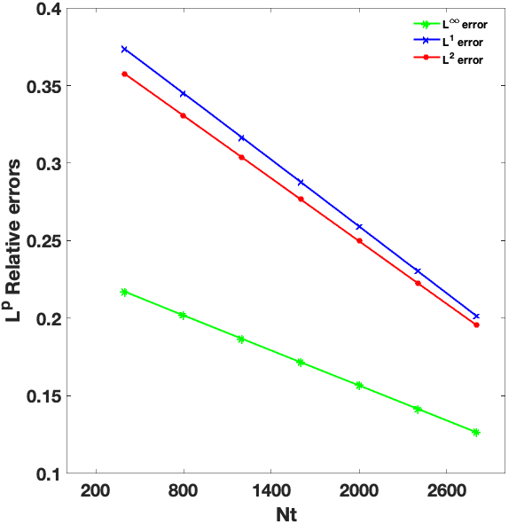
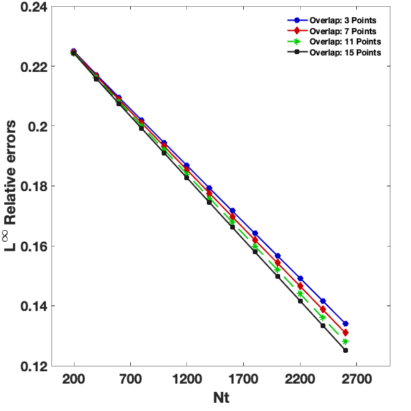
To study the effect of the overlap of the subdomains on the convergence, in Figure 9 we plot the relative error (28) versus the number of pseudo time steps for 5, 9, 11, and 15 overlap points. We notice that the error decreases as the number of the overlap points increases.
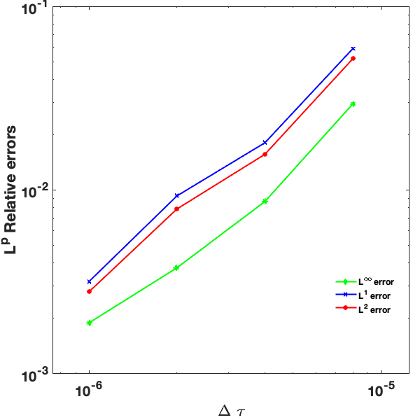
In what follows we study the convergence of the steady state solution obtained by the DDPMA algorithm to the steady state single domain solution of the parabolic Monge-Ampère equation (6). We compute the DDPMA steady state solution using four subdomains for and . A tolerance is used to detect the steady state solution; the time stepping is stopped when two successive solutions agree within the tolerance. Figure 10 presents the plots of the relative errors versus . We notice here that as gets smaller the relative errors decrease which illustrates the convergence of the DDPMA steady state solution to the steady state solution obtained on a single domain.
4.5 Quality measures of the DDPMA adaptive meshes
In this subsection, we compute the quality measure of the adaptive meshes computed using the DDPMA method. In , the adaptive mesh on the physical domain is formed by combining the adaptive meshes computed on each of the four subdomains On each subdomain , the adaptive mesh is obtained as an image of a coordinate transformation computed using the PMA method. We use a mesh quality measure as described in [22, 57] which is given by
| (29) |
where is the DD solution obtained by combining the steady state solutions of the parabolic Monge-Ampère equation on the subdomains , is the area (in 2D) or volume (in 3D) of the computational domain, and J is the determinant of the Jacobian matrix of the coordinate transformation. Note that is defined pointwise for each grid node in the domain . We compute the maximum and norms of the mesh quality measure, and , respectively.
The mesh quality measure (29) is computed for the adaptive mesh obtained by the DDPMA method using 4 slabs and a block decomposition. Here, the mesh quality measure is computed for two different grid resolutions, namely using and mesh points.
The results from Table 3 show that the adaptive meshes computed using the DDPMA method and PMA method on a single domain have very similar mesh quality measures. This indicates excellent agreement between the adaptive mesh obtained using the DDPMA and the adaptive mesh obtained using the PMA method employed on the entire domain. Moreover, the fact that the values in the table are close to one indicates that the meshes satisfy the equidistribution principle (2) closely.
| 4 Slabs DD | ||||
|---|---|---|---|---|
| Block DD | ||||
| Whole Domain | ||||
5 Conclusions
We have developed a non-iterative overlapping domain decomposition approach for fast and efficient computation of adaptive moving meshes in multi-dimensions. The computational domain is split into subdomains and the parabolic Monge-Ampère method is employed to compute the adaptive mesh on each subdomain. The numerical experiments show that the DDPMA method is more efficient than the PMA method applied on the whole domain. This result is significant especially when solving physical problems on large 2D domains and/or in three spatial dimensions. The computations involved here are performed on both a single processor (for the serial computations) and 4-processors (for the parallel computations). The number of the processors utilized can be increased by increasing the number of subdomains. The results indicate that the parallel computations can be implemented efficiently with the DDPMA method. We have also studied the convergence of the adaptive mesh computed using the DDPMA method to the adaptive mesh computed by the PMA method applied to the whole domain.
References
References
- [1] E. Dorfi, L. Drury, Simple adaptive grids for 1-D initial value problems, J. Comput. Phys. 69 (1) (1987) 175–195.
- [2] J. F. Thompson, Z. U. A. Warsi, C. W. Mastin, Numerical Grid Generation: Foundations and Applications, North-Holland Publishing Co., New York, 1985.
- [3] D. A. Anderson, Equidistribution schemes, Poisson generators, and adaptive grids, Appl. Math. Comp. 24 (3) (1987) 211–227.
- [4] W. Huang, R. D. Russell, Adaptive Moving Mesh Methods, Springer, New York, USA, 2011.
- [5] K. Miller, Moving finite elements II, SIAM J. Numer. Anal. 18 (6) (1981) 1033–1057.
- [6] K. Miller, R. N. Miller, Moving finite elements I, SIAM J. Numer. Anal. 18 (6) (1981) 1019–1032.
- [7] R. Gelinas, S. Doss, K. Miller, The moving finite element method: Applications to general partial differential equations with multiple large gradients, J. Comput. Phys. 40 (1) (1981) 202–249.
- [8] S. Adjerid, J. E. Flaherty, A moving finite element method with error estimation and refinement for one-dimensional time dependent partial differential equations, SIAM J. Numer. Anal. 23 (4) (1986) 778–796.
- [9] R. Furzeland, J. Verwer, P. Zegeling, A numerical study of three moving-grid methods for one-dimensional partial differential equations which are based on the method of lines, J. Comput. Phys. 89 (2) (1990) 349–388.
- [10] D. Hawken, J. Gottlieb, J. Hansen, Review of some adaptive node-movement techniques in finite-element and finite-difference solutions of partial differential equations, J. Comput. Phys. 95 (2) (1991) 254–302.
- [11] S. Adjerid, J. E. Flaherty, P. K. Moore, Y. J. Wang, High-order adaptive methods for parabolic systems, Phys. D 60 (1-4) (1992) 94–111.
- [12] W. Huang, Y. Ren, R. D. Russell, Moving mesh partial differential equations (MMPDES) based on the equidistribution principle, SIAM J. Numer. Anal. 31 (3) (1994) 709–730.
- [13] W. Huang, R. D. Russell, Moving mesh strategy based on a gradient flow equation for two-dimensional problems, SIAM J. Sci. Comput. 20 (3) (1999) 998–1015.
- [14] W. Huang, W. Sun, Variational mesh adaptation II: error estimates and monitor functions, J. Comput. Phys. 184 (2) (2003) 619–648.
- [15] W. Cao, W. Huang, R. D. Russell, A moving mesh method based on the geometric conservation law, SIAM J. Sci. Comput. 24 (1) (2002) 118–142.
- [16] G. Beckett, J. A. Mackenzie, A. Ramage, D. M. Sloan, Computational solution of two-dimensional unsteady PDEs using moving mesh methods, J. Comput. Phys. 182 (2) (2002) 478–495.
- [17] C. de Boor, Good approximation by splines with variable knots. II, in: Conference on the Numerical Solution of Differential Equations (Univ. Dundee, Dundee, 1973), Springer, Berlin, 1974, pp. 12–20. Lecture Notes in Math., Vol. 363.
- [18] W. Huang, Y. Ren, R. D. Russell, Moving mesh methods based on moving mesh partial differential equations, J. Comput. Phys. 113 (2) (1994) 279–290.
- [19] T. Tang, Moving mesh methods for computational fluid dynamics flow and transport, in: Recent Advances in Adaptive Computation (Hangzhou, 2004), Vol. 383 of AMS Contemporary Mathematics, Amer. Math. Soc., Providence, RI, 2005, pp. 141–173.
- [20] C. J. Budd, W. Huang, R. D. Russell, Adaptivity with moving grids, Acta Numerica 18 (2009) 111–241.
- [21] C. J. Budd, J. F. Williams, Moving mesh generation using the parabolic Monge-Ampère equation., SIAM J. Sci. Comput. 31 (5) (2009) 3438–3465.
- [22] M. Sulman, J. F. Williams, R. D. Russell, Optimal mass transport for higher dimensional adaptive grid generation, J. Comput. Phys. 230 (9) (2011) 3302–3330.
- [23] L. Chacón, G. Delzanno, J. Finn, Robust, multidimensional mesh-motion based on Monge-Kantorovich equidistribution, J. Comput. Phys. 230 (1) (2011) 87–103.
- [24] G. Monge, Mémoire sur la théorie des déblais at des remblais, in: Histoire de l’Académie Royale des Sciences de Paris, 1781, pp. 666–704.
- [25] L. V. Kantorovich, On a problem of Monge, Uspehki Mat. Nauk 3 (1948) 225–226.
- [26] J.-D. Benamou, Y. Brenier, A computational fluid mechanics solution to the Monge-Kantorovich mass transfer problem, Numer. Math. 84 (3) (2000) 375–393.
- [27] M. Sulman, J. Williams, R. D. Russell, An efficient approach for the numerical solution of the Monge-Ampère equation, Appl. Numer. Math. 61 (3) (2011) 298–307.
- [28] M. Gander, R. Haynes, Domain decomposition approaches for mesh generation via the equidistribution principle, SIAM J. Numer. Anal. 50 (2012) 2111–2135.
- [29] R. D. Haynes, F. Kwok, Discrete analysis of domain decomposition approaches for mesh generation via the equidistribution principle, Math. Comp. 86 (303) (2017) 233–273.
- [30] R. Haynes, A. Howse, Generating equidistributed meshes in 2D via domain decomposition, in: Domain Decomposition Methods in Science and Engineering XXI, Vol. 98 of Lecture Notes in Computational Science and Engineering, Springer, 2014, pp. 167–178.
- [31] A. Bihlo, R. D. Haynes, Parallel stochastic methods for PDE based grid generation, Comput. Math. Appl. 68 (8) (2014) 804–820.
- [32] R. D. Haynes, Domain decomposition approaches for PDE based mesh generation, in: Domain decomposition methods in science and engineering XXIV, Vol. 125 of Lect. Notes Comput. Sci. Eng., Springer, Cham, 2018, pp. 73–86.
- [33] H. A. Schwarz, Uber einige abbildungsaufgaben, Ges. Math. Abh. 11 (1869) 65–83.
- [34] P. Lions, On the Schwarz alternating method I, in: T. F. Chan, et al. (Eds.), Domain Decomposition Methods, SIAM, Philadelphia, 1989, Ch. 10.
- [35] I. Babuska, On the Schwarz algorithm in the theory of differential equations of mathematical physics, Tchecosl. Math J. 8 (1958) 328–342.
- [36] S. G. Michlin, On the Schwarz algorithm, Dokl. Acad. N. USSR. 77 (1951) 569–571.
- [37] J. K. White, A. Sangiovanni-Vincentelli, Waveform relaxation, in: Relaxation Techniques for the Simulation of VLSI Circuits, Springer, Boston, MA, 1987, pp. 79–100.
- [38] R. Jeltsch, B. Pohl, Waveform relaxation with overlapping splittings, SIAM J. Sci. Comput., 16 (1) (1995) 40–49.
- [39] M. J. Gander, Overlapping Schwarz waveform relaxation for parabolic problems, in: In Proceedings of Algoritmy’97, 1997, pp. 425–431.
- [40] M. J. Gander, H. Zhao, Overlapping Schwarz waveform relaxation for the heat equation in n dimensions, BIT Numer. Math. 42 (4) (2002) 779–795.
- [41] S. Vandewalle, M. J. Gander, Optimized overlapping Schwarz methods for parabolic PDEs with time-delay, in: T. J. Barth, M. Griebel, D. E. Keyes, R. M. Nieminen, D. Roose, T. Schlick, R. Kornhuber, R. Hoppe, J. Périaux, O. Pironneau, O. Widlund, J. Xu (Eds.), Domain Decomposition Methods in Science and Engineering, Springer Berlin Heidelberg, Berlin, Heidelberg, 2005, pp. 291–298.
- [42] P. Vabishchevich, Domain decomposition methods with overlapping subdomains for the time-dependent problems of mathematical physics, Comput. Methods Appl. Math. 8 (4) (2008) 393–405.
- [43] X.-C. Cai, Multiplicative Schwarz methods for parabolic problems, SIAM J.Sci. Comput. 15 (3) (1994) 587–603.
- [44] Z. Zheng, B. Simeon, L. Petzold, A stabilized explicit Lagrange multiplier based domain decomposition method for parabolic problems, J. Comput. Phys. 227 (10) (2008) 5272–5285.
- [45] L. Qin, X. Xu, Optimized Schwarz methods with Robin transmission conditions for parabolic problems, SIAM J. Sci. Comput. 31 (1) (2008) 608–623.
- [46] A. Mota, I. Tezaur, C. Alleman, The Schwarz alternating method in solid mechanics, Comput. Meth. Appl. Mech. Eng. 319 (1) (2017) 19–51.
- [47] M. A. Gnatyuk, V. M. Morozov, On the Schwarz alternating method for solving electromagnetic problems, in: 2015 XXth IEEE International Seminar/Workshop on Direct and Inverse Problems of Electromagnetic and Acoustic Wave Theory (DIPED), Lviv, Ukraine, 2015, pp. 132–135.
- [48] Z. Dai, Q. Du, B. Liu, Schwarz alternating methods for anisotropic problems with prolate spheroid boundaries, SpringerPlus 5 (1423) (2016) 1.
- [49] C. N. Dawson, Q. Du, T. F. Dupont, A finite difference domain decomposition algorithm for numerical solution of the heat equation, Math. Comput. 57 (195) (1991) 63–71.
- [50] C. Dawson, T. Dupont, Explicit/implicit, conservative domain decomposition procedures for parabolic problems based on block-centered finite differences, SIAM J. Numer. Anal. 31 (4) (1994) 1045–1061.
- [51] Y. Zhang, Stable, globally non-iterative, non-overlapping domain decomposition methods for the efficient solution of parabolic evolutionary systems, Ph.D. thesis, Louisiana State University (2000).
- [52] G. Yuan, Z. Sheng, X. Hang, The unconditional stability of parallel difference schemes with second order convergence for nonlinear parabolic system, J. Partial Diff. Eq. 20 (2007) 45–64.
- [53] D. Yang, Non-iterative parallel Schwarz algorithms based on overlapping domain decomposition for parabolic partial differential equations, Math. Comput. 86 (308) (2017) 2687–2718.
- [54] G. Xue, H. Feng, A new parallel algorithm for solving parabolic equations, Adv. Diff. Eq. 2018 (174) (2018) 1–16.
- [55] M. Knott, C. S. Smith, On the optimal mapping of distributions, J. Optim. Theory Appl. 43 (1) (1984) 39–49.
- [56] Y. Brenier, Polar factorization and monotone rearrangement of vector-valued functions, Comm. Pure Appl. Math. 44 (4) (1991) 375–417.
- [57] W. Huang, Measuring mesh qualities and application to variational mesh adaptation, SIAM J. Sci. Comput. 26 (2005) 1643–1666.