Comparing Strategies for Local FWI: FD Injection and Immersive Boundary Conditions
Fernanda Farias and Reynam Pestana
Abstract
Conventional Full Waveform Inversion requires calculating the objective function to be minimized and construction a gradient using the whole property model, when is often the case where geoscientist are only interested in a local region. In this study, we use two strategies to perform local FWI in time domain. One that disregards the interaction of the locally altered model with the exterior (FD injection) and the second that can take these iterations into account (Immersive Boundary Conditions). Numerical tests show the influence of whether or not to set aside these interactions for different accuracy of the exterior model.
1 Introduction
The full waveform inversion (FWI) technique is often used to provide high resolution propriety model of the subsurface. For this purpose it is necessary to compute both the forward and the adjoint source extrapolation of the entire model, even when the geoscientist is usually interested in a small portion of the model. This can sound as a waste of calculation and, to save time and speed up calculations, attempts have been made to reproduce the wavefield inside a local domain as if it had been generated using the entire model. In this work, we compare the results of two different approaches to perform a localized FWI.
The first strategy uses the finite difference injection method proposed by Robertsson and Chapman, (2000), which basically stores the wavefields on the boundary of the local domain to inject then after alterations have occurred, whereas the surrounding model is kept unaltered. However, this method is unable to recover the high-order long-range interaction between the local and the surrounding model. Due to its lower cost and straightforward implementation, it has already been used for FWI applications in 3D and with the elastic wave equation (Borisov et al.,, 2015).
The second and more computationally expensive approach, which we adopt here, makes use of the technique introduced by van Manen et al., (2007) and extended by Vasmel et al., (2013) for two and three dimensions, the so-called immersive boundary condition (IBC), which is capable of mimic, under numerical precision, the wavefield in a domain which is immersed in a larger one. It requires a large number of Green’s functions computations in the full domain to calculate the exact boundary conditions at every time step, and by doing so, this methodology can account for every interaction that the local domain may have with the exterior domain. Lately, IBC has been used in the frequency domain for salt boundary problems by Willemsen et al., (2016), and it was also tested using a randomized singular value decomposition to compute the low-rank approximation of the Green’s function in two and three dimension (Kumar et al.,, 2019) .
To observe the effect of high-order long-range interaction for localized FWI applications, we compare the velocity model inverted using the two localized techniques mentioned above with the conventional inversion in the time domain using the vector acoustic equations.
2 Method and Theory
FD Injection
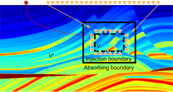
The finite-difference injection method used to model seismic data after local model alterations connects the solution of different regions by repositioning source and receiver wavefields on the surface of the local regions. This is done after one simulation using the whole model, in which both the pressure and the particle velocity wavefields are stored at the injection surface. After alterations in the local model, these wavefields will act as a new source distribution for the local simulations. To avoid undesired events, a larger surface should involve the injection surface as depicted in on the right side of Figure 1(a), in a way that the localized simulations are carried out only inside the continuous line in Figure 1(a). Both forward calculation and gradient constructions are carried out exclusively inside this local domain. The computation of the gradient requires redatuming, i.e., to replace receivers from the physical to the virtual position. This step is carried out for all four sides of the local domain. This can be done by extrapolating the observed wavefield from its recorded positions to the virtual receivers, assuming that the background velocity model used for calculating the Green function is sufficiently accurate. An alternative for redatuming for localised FWI is to use the method proposed by Kohnke and Sava, (2019), who introduced an iterative least-squares problem linking the wavefield on the local domain surface to the observation data.
Immersive Boundary Conditions
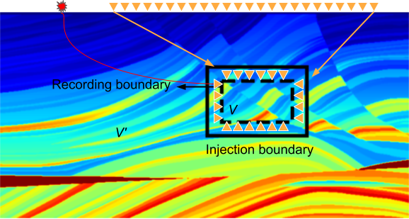
To overcome the inability of the FD injection method to account for the high-order interactions between the scattered wavefield and the unaltered exterior domain, the so-called immersive boundary condition calculates the boundary conditions at the limit of the local model "on-the-fly" so that nothing is neglected. To do that, an auxiliary transparent surface within the local model is defined (see Figure 1(b)), after that the wavefield that is recorded in that auxiliary surface is propagated to the injection surface using a time-recursive discrete version of the Kirchoff-Helmholtz integral:
| (1) |
The wavefield reconstructed at the surface is updated and injected at every time step and it carries every interaction with the extended model through the Green’s functions presented in Equation 1. The Green’s functions are calculated at every point on the record surface and stored at the injection surface, although Broggini et al., (2018) made a sensitivity study concerning the spatial subsampling on the recording surface. In either way, the convolutions present in Equation 1 can be quite time consuming depending on the model parameters. For a detailed description of the implementation and theory of the IBC methodology we refer to Broggini et al., (2017).
Full Waveform Inversion using Vector Acoustic Equations
Although FWI using vector acoustic equations are still less usual than the conventional second order acoustic wave equation, a few studies show the applications of this technique to synthetic (Akrami et al.,, 2017) and field data (Hwang et al.,, 2019), attempting to explore the benefits of using direction data into the inversion. Here, we use the pressure field to fit the data, using the Equation 2, and the gradient expression (Equation 3) to construct it locally as proposed here.
| (2) |
| (3) |
3 Examples
Horizontal reflector model
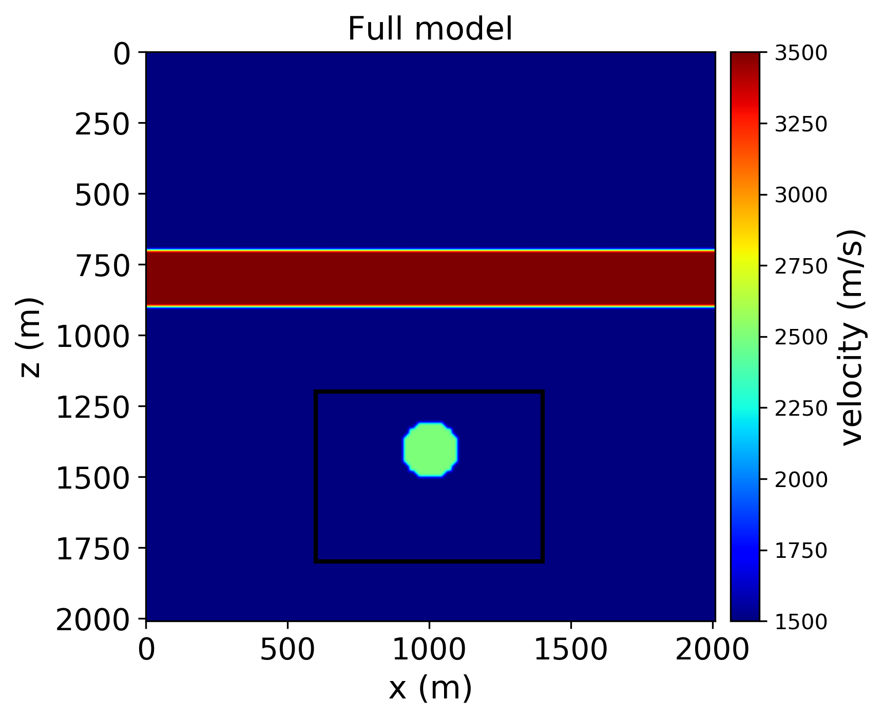
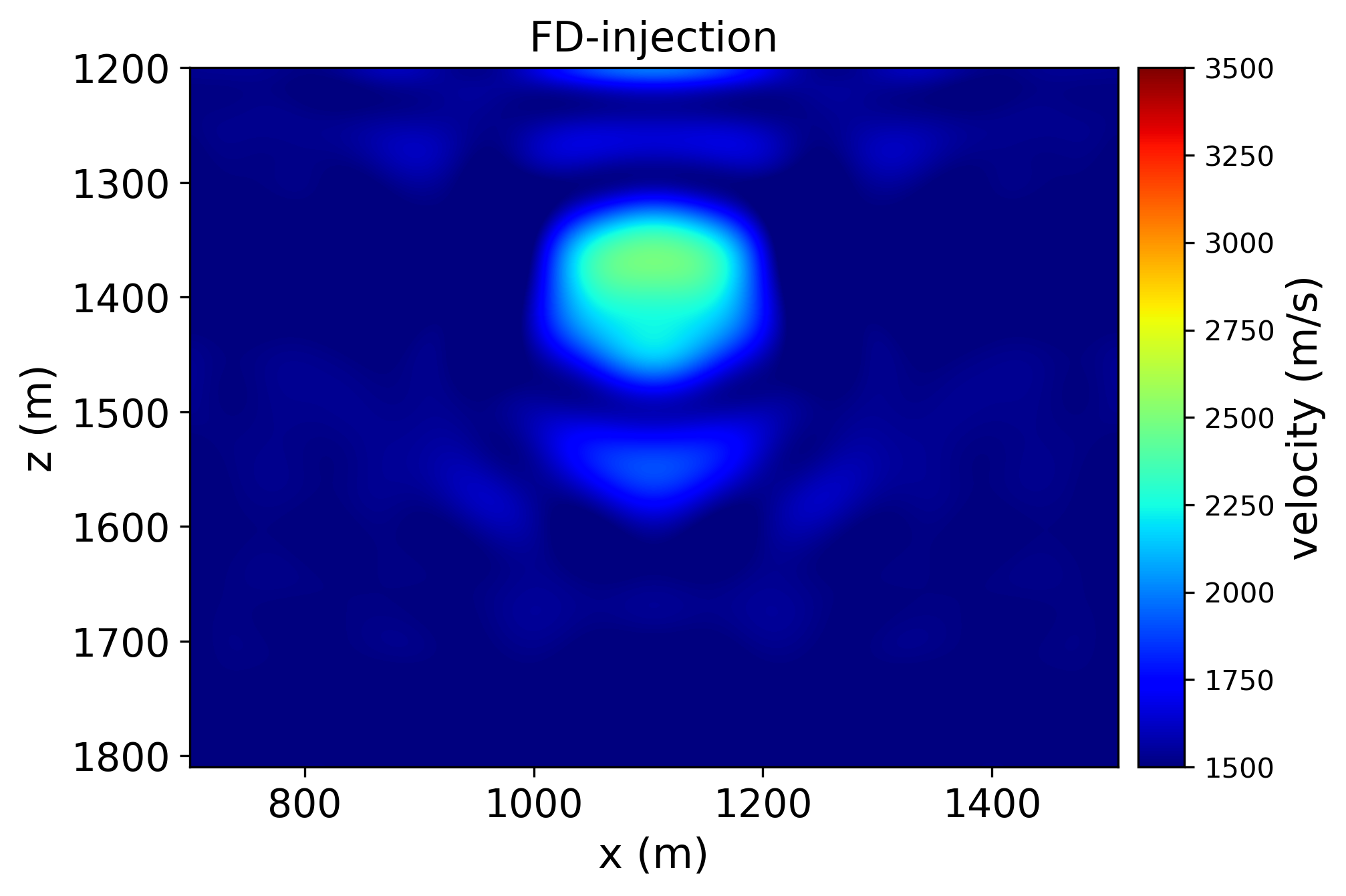
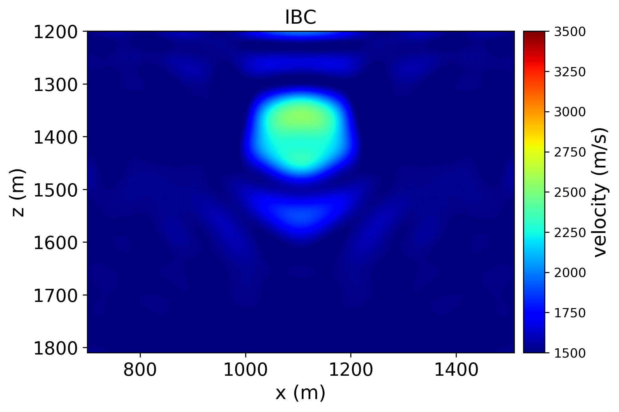
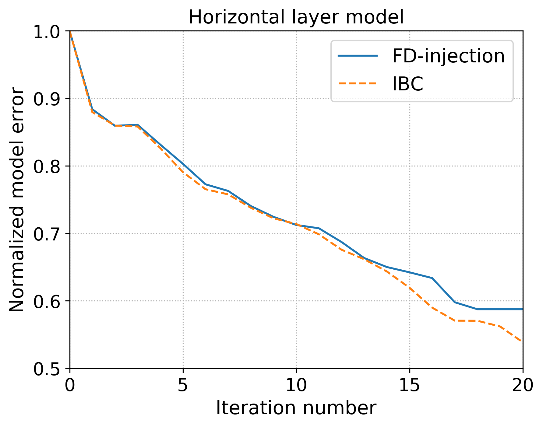
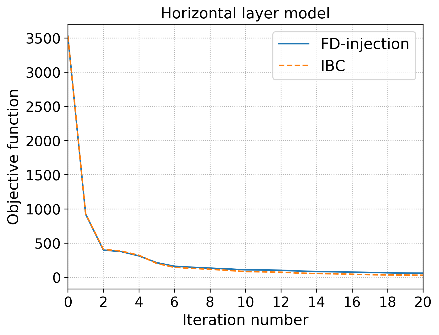
For the simple horizontal reflector model, displayed in Figure 2(a), the background was exact the same as the true model except for the round anomaly below the reflector. This particular case, is a good scenario for IBC methodology. Since the background velocity model is the same as the true model outside the localized inversion, IBC can perfectly predict the interaction between the local model and the outside, which is normally not true. In this example, the density model is considered constant. Each source is placed at a depth of 10 m and regularly spaced at 300 m interval. The peak frequency is set to 5 Hz.
Marmousi model
To investigate how both methods behave in case the model outside the local domain is inaccurate, which is usually true, we perform local FWI for the Marmousi model considering as local domain the region inside the rectangle in Figure 1(b). As for the horizontal layer model, the source is placed at a depth of 10 m and regularly spaced at 300 m interval, with peak frequency of 5 Hz.
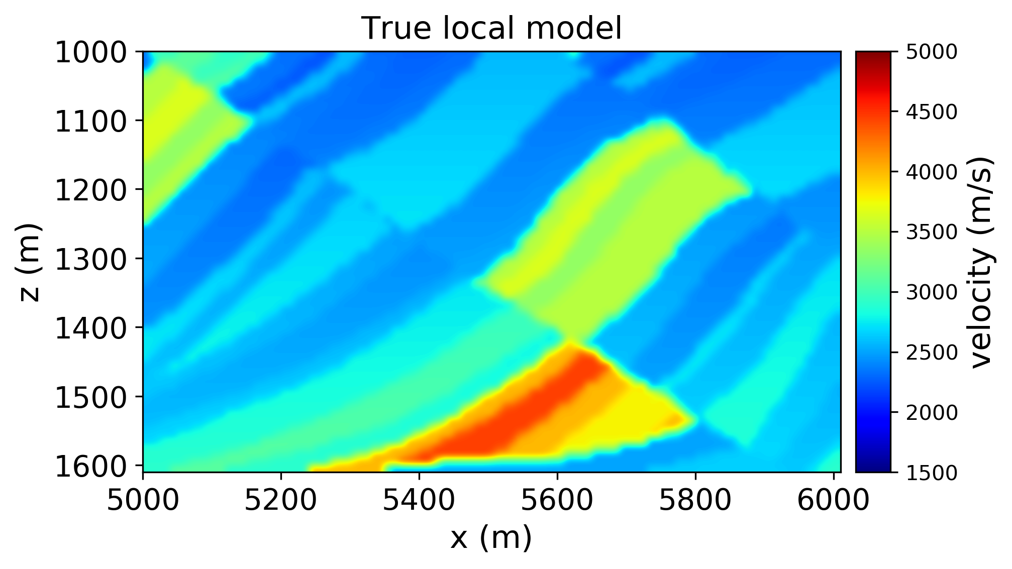
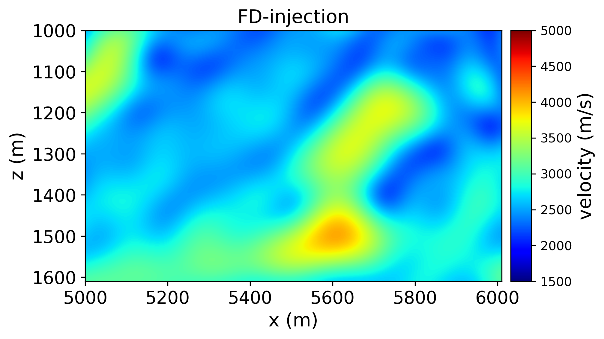
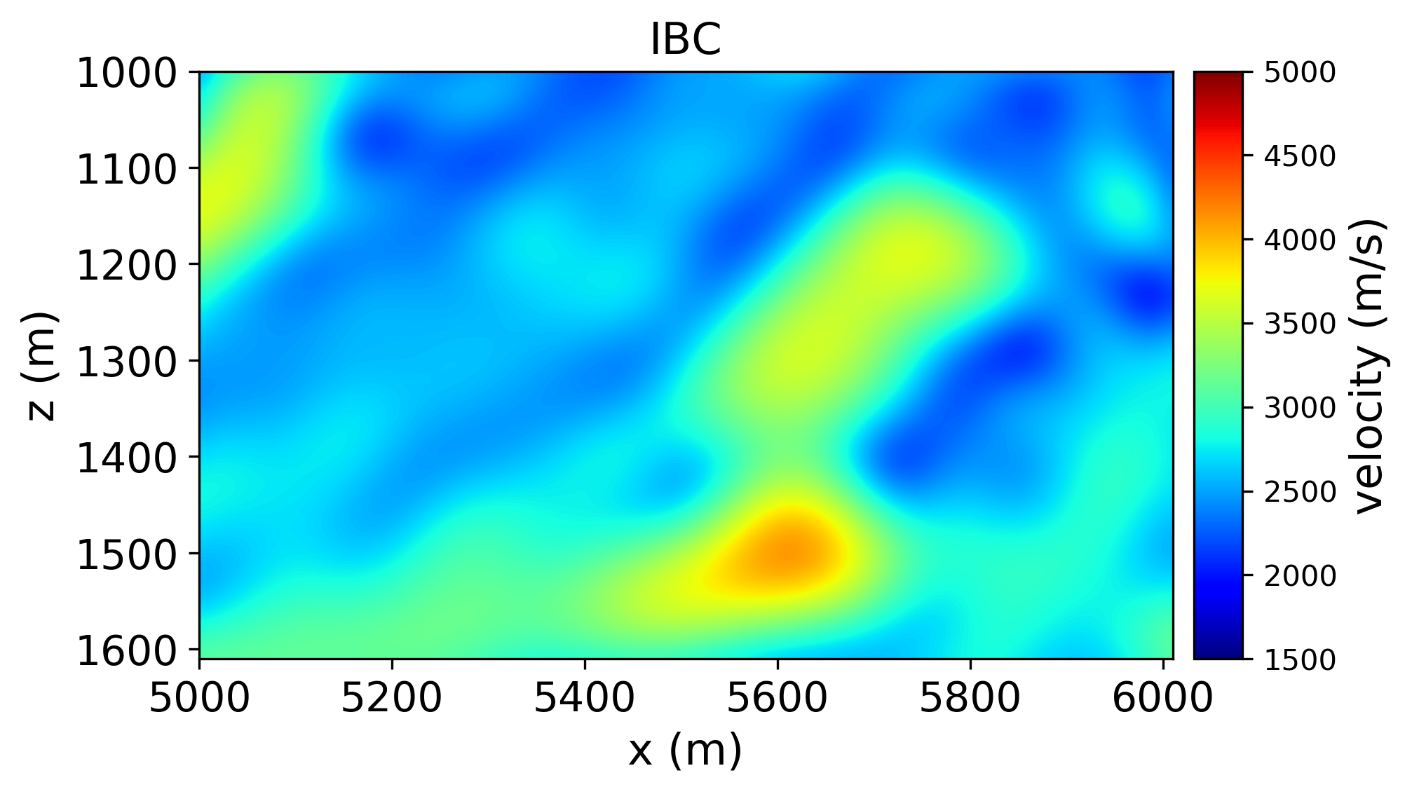
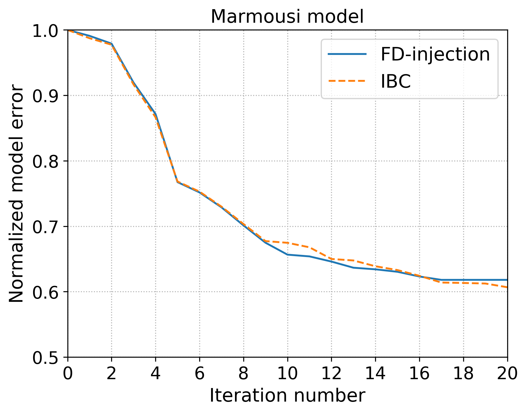
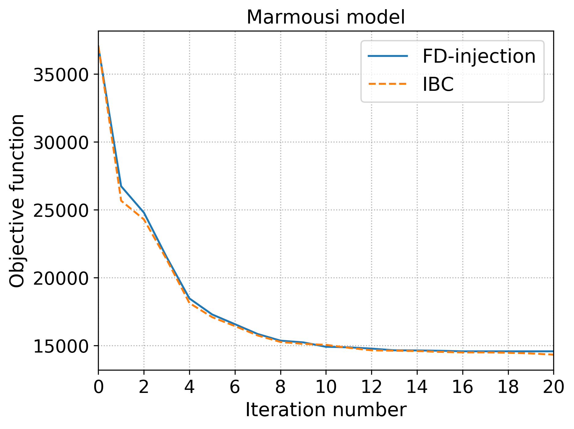
For the two models considered, the local FWI using IBC shows lower values for the normalized error model and objective function value at the end of 20 iterations than the one using the FD injection. Although, for the parameters considered here, inverted velocities are reasonable recovered using both methodologies.
4 Conclusions
Numerical tests indicate that when the overburden is the same as the one where the observed data was acquired, a convenient situation for time-lapse inversion since physical properties are likely to change in the reservoir area, FWI based on FD injection and IBC provide a reasonable inverted velocity model, although IBC shows lower model error and objective function values. In the case where we use as background velocity model a smoothed version of the true model, the IBC still gives better results but not very different from the one using the FD injection methodology.
5 Acknowledgements
We would like to thank Filippo Broggini for very helpful discussions. We acknowledge Alan Souza from PETROBRAS and Oscar Mojica from SENAI CIMATEC for discussions and help with numerical tests.
References
- Akrami et al., (2017) Akrami, S.M., Zheglova, P. and Malcolm, A. [2017] An algorithm for vector data full-waveform inversion. In: SEG Technical Program Expanded Abstracts 2017, Society of Exploration Geophysicists, 1568–1572.
- Borisov et al., (2015) Borisov, D., Singh, S.C. and Fuji, N. [2015] An efficient method of 3-D elastic full waveform inversion using a finite-difference injection method for time-lapse imaging. Geophysical Journal International, 202(3), 1908–1922.
- Broggini et al., (2018) Broggini, F., Athanasopoulos, N., Gray, M. and van Manen, D. [2018] Sensitivity Study of the Immersive Boundary Condition Method. In: 80th EAGE Conference and Exhibition 2018.
- Broggini et al., (2017) Broggini, F., Vasmel, M., Robertsson, J.O. and van Manen, D.J. [2017] Immersive boundary conditions: Theory, implementation, and examples. Geophysics, 82(3), T97–T110.
- Hwang et al., (2019) Hwang, J., Oh, J.W., Min, D.J., Shin, Y. and Lee, J.W. [2019] 2D acoustic FWI using the multicomponent marine data: Application to North Sea OBC data. In: SEG Technical Program Expanded Abstracts 2019, Society of Exploration Geophysicists, 1660–1664.
- Kohnke and Sava, (2019) Kohnke, C. and Sava, P. [2019] Inversion of vector-acoustic data in a local domain. In: SEG Technical Program Expanded Abstracts 2019, Society of Exploration Geophysicists, 1531–1535.
- Kumar et al., (2019) Kumar, R., Willemsen, B., Herrmann, F.J. and Malcolm, A. [2019] Enabling numerically exact local solver for waveform inversion—a low-rank approach. Computational Geosciences, 1–19.
- van Manen et al., (2007) van Manen, D.J., Robertsson, J.O. and Curtis, A. [2007] Exact wave field simulation for finite-volume scattering problems. The Journal of the Acoustical Society of America, 122(4), EL115–EL121.
- Robertsson and Chapman, (2000) Robertsson, J.O. and Chapman, C.H. [2000] An efficient method for calculating finite-difference seismograms after model alterations. Geophysics, 65(3), 907–918.
- Vasmel et al., (2013) Vasmel, M., Robertsson, J.O., van Manen, D.J. and Curtis, A. [2013] Immersive experimentation in a wave propagation laboratory. The Journal of the Acoustical Society of America, 134(6), EL492–EL498.
- Willemsen et al., (2016) Willemsen, B., Malcolm, A. and Lewis, W. [2016] A numerically exact local solver applied to salt boundary inversion in seismic full-waveform inversion. Geophysical Journal International, 204(3), 1703–1720.