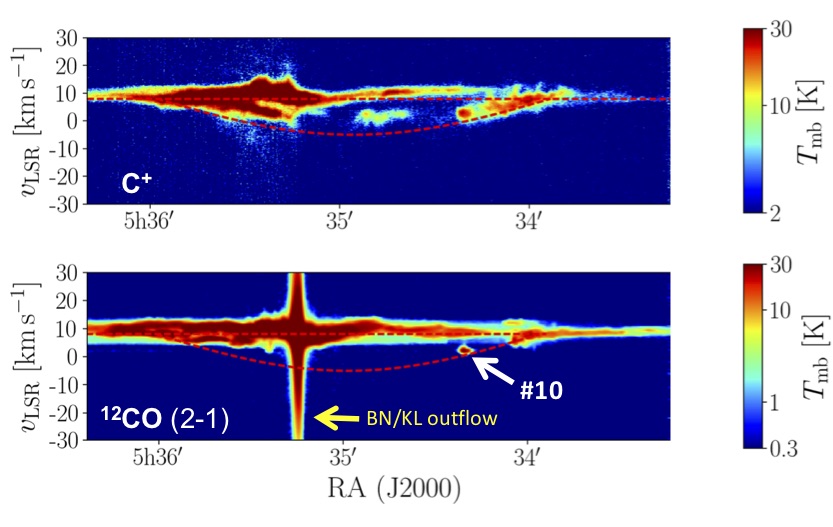
Molecular globules in the Veil bubble of Orion††thanks: Based on IRAM 30m telescope observations. IRAM is supported by INSU/CNRS (France), MPG (Germany), and IGN (Spain).
Strong winds and ultraviolet (UV) radiation from O-type stars disrupt and ionize their molecular core birthplaces, sweeping up material into parsec-size shells. Owing to dissociation by starlight, the thinnest shells are expected to host low molecular abundances and therefore little star formation. Here, we expand previous maps made with observations using the IRAM 30m telescope (at 11′′ 4,500 AU resolution) and present square-degree 12CO and 13CO ( = 2-1) maps of the wind-driven “Veil bubble” that surrounds the Trapezium cluster and its natal Orion molecular core (OMC). Although widespread and extended CO emission is largely absent from the Veil, we show that several CO “globules” exist that are blueshifted in velocity with respect to OMC and are embedded in the [C ii] 158 m-bright shell that confines the bubble. This includes the first detection of quiescent CO at negative local standard of rest (LSR) velocities in Orion. Given the harsh UV irradiation conditions in this translucent material, the detection of CO globules is surprising. These globules are small ( 7,100 AU), not massive ( 0.3 ), and are moderately dense: 4104 cm-3 (median values). They are confined by the external pressure of the shell, 107 cm-3 K, and are likely magnetically supported. They are either transient objects formed by instabilities or have detached from pre-existing molecular structures, sculpted by the passing shock associated with the expanding shell and by UV radiation from the Trapezium. Some represent the first stages in the formation of small pillars, others of isolated small globules. Although their masses ( ) do not suggest they will form stars, one globule matches the position of a known young stellar object. The lack of extended CO in the “Veil shell” demonstrates that feedback from massive stars expels, agitates, and reprocesses most of the disrupted molecular cloud gas, thereby limiting the star-formation rate in the region. The presence of molecular globules is a result of this feedback.
Key Words.:
galaxies: ISM – H II regions – ISM: bubbles – ISM: clouds — ISM: individual (Orion)1 Introduction
Massive stars dominate the injection of UV radiation into the interstellar medium (ISM) and of mechanical energy through stellar winds and supernova explosions. The energy and momentum injected by photoionization, radiation pressure, and stellar winds from young O-type stars ionize and disrupt their natal molecular cloud cores, creating H ii regions and blowing parsec-size bubbles enclosed by shells of denser swept-up material (e.g., Weaver et al., 1977; Churchwell et al., 2006; Deharveng et al., 2010). These feedback processes may locally regulate the formation of new stars, and globally drive the evolution of the ISM in galaxies as a whole (e.g., Krumholz et al., 2014; Rahner et al., 2017; Haid et al., 2018).
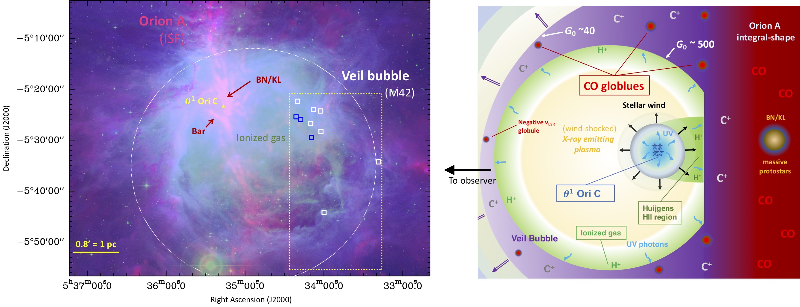
The iconic Extended Orion Nebula (M42) is photoionized by UV photons emitted mainly from the most massive star in the Trapezium cluster, Ori C (type O7V and 61048 photons s-1; e.g., O’Dell, 2001; Simón-Díaz et al., 2006; Gravity Collaboration et al., 2018). In addition, the characteristic bubble-shape (4 pc in diameter) and overall dynamics of M42 seem ultimately driven by the strong wind emanating from Ori C (Güdel et al., 2008; Pabst et al., 2019). The foreground material that surrounds the Trapezium and its natal molecular core-1 (OMC-1, located behind the cluster, e.g., Genzel & Stutzki, 1989; Bally, 2008) are generically known as the “Veil” (O’Dell, 2001; van der Werf et al., 2013; Troland et al., 2016; Abel et al., 2019). The “Veil bubble” is filled with an X-ray-emitting (wind-shocked) million-degree plasma (Güdel et al., 2008). As delineated by the H emission, the inside of this bubble is also an H ii region photo-ionized by UV radiation from Ori C. In the far side, the bubble is confined by dense molecular gas at the surface of the OMC (Rodríguez-Franco et al., 1998; Goicoechea et al., 2019) and, in the near side, by an expanding half-shell of warm gas (100 K) and dust (see sketch in Fig. 1). The swept-up material in the shell is very bright in the - fine-structure emission of C+ (the well-known [C ii] 158 m line). In Pabst et al. (2019) we obtained square-degree velocity-resolved images of the [C ii] 158 m emission with SOFIA, and showed that the mechanical energy from the stellar wind from Ori C (terminal velocity of 2,500 km s-1; Stahl et al., 1996) is effectively converted into kinetic energy of the shell. This stellar wind causes more disruption of OMC-1 (well before any supernova explosion) than photo-ionization or photo-evaporation (Pabst et al., 2019).
Although not the most numerous or massive star cluster in the Milky Way, the proximity of the Orion nebula, the Trapezium stars, and the molecular core OMC-1 (the closest core that hosts ongoing massive-star formation) enables us to study star formation and stellar feedback in great spatial detail (like in our previous works, here we adopt 414 pc; e.g., Menten et al., 2007).
As in other thin shells around high-mass stars, the intense UV radiation in M42 suggests very low molecular abundances in the “Veil shell”. Indeed, previous observations of the line of sight toward the Trapezium stars imply small columns of material in the Veil (O’Dell, 2001), 1-2 mag of visual extinction (), and also low molecular gas fractions ((H2)/(H) 10-4; where is the abundance with respect to H nuclei, Abel et al., 2006).
CO, the second most abundant molecule in the ISM, had not been detected toward the Veil before. As the emission from cold H2 is not directly observable either (e.g., Bolatto et al., 2013), the lack of detectable CO emission poses uncertain constraints on the measurable mass of molecular material that escapes detection in wide-field CO radio surveys (Grenier et al., 2005; Planck Collaboration et al., 2011). This extended “CO-dark” molecular gas (when the CO column density, (CO), is too low to be detected) may represent 30% of the molecular gas mass in the Milky Way (Grenier et al., 2005; Wolfire et al., 2010). This fraction can be much higher in the ISM of low-metallicity galaxies (Madden et al., 1997) characterized by a higher penetration of stellar UV radiation. In this context, the Orion’s Veil is an interesting nearby template to study the origin and properties of the vast neutral halos that surround many star-forming regions.
This paper is organized as follows. In Sect. 2 we describe the new CO ( = 2-1) mapping observations. In Sect. 3 we present the main observational result of this work, namely the detection of globules embedded in the shell that confines the Veil bubble. In Sect. 4 we analyze the environment and the properties of these globules, and in Sect. 5 we discuss their origin and evolution.
2 Observations and data reduction
We obtained new 12CO, 13CO, and C18O ( = 2-1) fully sampled maps of Orion A using the IRAM 30m telescope (Pico Veleta, Spain). The bright central region () around OMC-1 was originally mapped in 2008 (Berné et al., 2014) with the multi-beam receiver HERA at 0.4 km s-1 resolution (Schuster et al., 2004). In order to cover the larger area (1.2 square-degree) mapped by us in the [C ii] 158 m line with SOFIA/GREAT at comparable angular resolution (Legacy Program led by A. G. G. M. Tielens) we started to expand the CO maps using EMIR (Carter et al., 2012) and FFTS backends at the 30m telescope. These new observations of fainter regions in Orion A were carried out in October 2018, March 2019, November 2019, and February 2020, so far employing 100 h of telescope time, and are part of the Large Program “Dynamic and Radiative Feedback of Massive Stars” (PI: J. R. Goicoechea).
The 12CO =2-1 (230.5 GHz), 13CO =2-1 (220.4 GHz), and C18O =2-1 (219.5 GHz) lines were simultaneously mapped with EMIR, providing an instantaneous bandwidth of 16 GHz per polarization, in combination with FFTS backends at 200 kHz resolution (0.25 km s-1). The half power beam width (HPBW) at 230.5 GHz is 10.7′′. The observing strategy consisted in mapping boxes of 534′′534′′ size using the on-the-fly (OTF) technique. Each box was mapped through 16 rectangular tiles of 8 OTF scans each, followed by a calibration measurement. In total, we employed about 12 min per tile. The scanning velocity was 9′′ s-1 and the dump time was 0.4 s. This combination provided three dumps per beam along the scanning direction. The separation between two successive raster lines was 4.2′′ (roughly beam/2.5) with the scanning direction reversed after each raster line (i.e., zigzag scanning mode). To avoid edge-effects between consecutive boxes, we overlapped the observation of each box edge by slightly more than one beam. In order to decrease stripping, each box was mapped twice, scanning in two orthogonal directions. We used a common reference position that we call REF, at an offset from the map center. We obtained deep spectra of the REF position using the frequency switching mode. These spectra do not show CO emission at the rms level of the map. The REF position was observed for 10 s after each raster line (taking 60 s) following the pattern REF–OTF–OTF–REF. Pointing was checked every 2 h and focus every 4 h or after sunset. We started every day with a pointed observation of the Orion Bar to cross-check the intensity of the CO lines. We estimate an absolute intensity error of about 15%.
The new data were first calibrated in the scale, and were then corrected for atmospheric absorption and spillover losses using the chopper-wheel method (Penzias & Burrus, 1973). Most of these observations were made under very good winter conditions (less than 2 mm of atmospheric precipitable water vapor). The receiver and system temperatures were typically 100 K and 200-300 K, respectively. For emission sources of brightness temperature (v) at a given velocity channel, the main-beam temperature is the most appropriate intensity scale (i.e., ) when the emission source fills the main beam of the telescope. Assuming a disk-like emission source of uniform and angular size varying from 25′′ to 90 ′′, the ratio / at 230 GHz goes from 1.0 to 1.2 at the IRAM 30m telescope (whereas / goes from 0.4 to 0.5; see Online material in Teyssier et al., 2002). Molecular clouds have complicated emission structures, spatially and in velocity, meaning that the scale is widely used as a good compromise when the emission sources are smaller than the very wide antenna error beams (for the IRAM 30m telescope, see Greve et al., 1998). Here we converted the intensity scale from to () using the main-beam efficiency and forward efficiency appropriate for each frequency ( = 0.59 and = 0.92 at 230 GHz).
Data reduction was carried out with the GILDAS software111http://www.iram.fr/IRAMFR/GILDAS. A polynomic baseline of order 1 or 2 was subtracted avoiding velocities with molecular emission. Finally, the spectra were gridded into a data cube through a convolution with a Gaussian kernel of approximately one-third the telescope HPBW. The typical (1) rms noise level achieved in the map is 0.25 K per 0.25 km s-1 velocity channel. This is typically a factor of more than three deeper than the rms of the large 12CO (1-0) map obtained by merging CARMA interferometric and NRO 45m telescope observations at 10′′8′′ angular resolution (Kong et al., 2018). Although these latter authors detect the stronger positive-velocity globules and other bright structures (their Fig. 8), the sensitivity in our maps allowed us to investigate faint and diffuse CO (2-1) emission structures and compact globules at local standard of rest (LSR) velocities significantly blueshifted from those of the OMC.
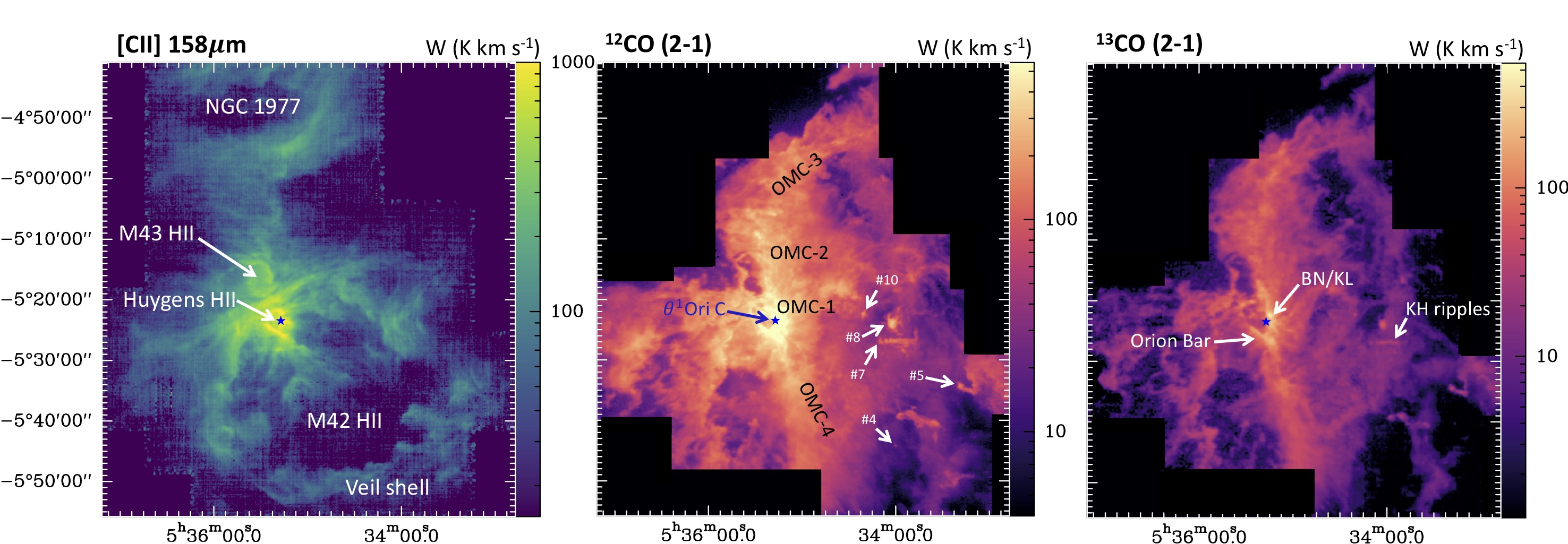
In order to compare with our SOFIA [C ii] 158 m map, we merged the older CO HERA observations with the expanded EMIR maps. Thanks to the improved new software, MRTCAL, at the 30 m telescope with calibration on a finer frequency grid, line calibration has slightly improved since 2017. In addition, telescope efficiencies have slightly changed as well. Hence, we took the new EMIR data as the reference for the CO line intensities. To do that, we re-observed a few common areas and produced scatter plots of the CO line integrated intensities (HERA vs. EMIR maps). The derived linear slopes deviate by , and we used this correction factor to scale up the HERA data. Figure 2 shows the (current) extent of the 12CO and 13CO (2-1) merged maps, whereas Fig. 3 zooms into the area of interest for this work.
In order to properly compare the 12CO (2-1), 13CO (2-1), and [C ii] 158 m line profiles at the same angular and spectral resolutions, we created cubes convolved, with a Gaussian kernel, to uniform resolutions of 16′′ and 0.4 km s-1, respectively. The convolved and smoothed CO maps were used in the line profile analysis (see Sect. 4 and Fig. 5 for the spectra) as well as in the position–velocity diagrams (Fig. 7 and 12 to 19). The typical rms noise in the smoothed 12CO (2-1) map is 0.16 K per 0.4 km s-1 channel. We used Gaussian fits to extract the line profile parameters of the blueshifted CO globules: spectral components peaking at LSR velocities lower than those of OMC (i.e., vLSR(7-10) km s-1; Bally et al., 1987; Berné et al., 2014; Kong et al., 2018). Line fit parameters are tabulated in Tables 4 and 5 of the Appendix. When appropriate, offsets in arcsec are given with respect to star Ori C, at 05h35m16.46s and .
3 Results
Figure 2 shows a square-degree area of the Orion A molecular complex. At visible wavelengths, the region is dominated by M42, the extended Orion nebula, ionized by the strong UV radiation field from Ori C (e.g., O’Dell, 2001). While in this region the [C ii] 158 m emission mostly traces UV-illuminated gas around H ii regions, the majority of the 12CO (2-1) and 13CO (2-1) integrated line emission arises from the molecular cloud behind (see sketch Fig. 1). The properties of the main star-forming cores (OMC-1, OMC-2, OMC-3, and OMC-4) have been extensively discussed in previous CO maps of the region (e.g., Bally et al., 1987; Shimajiri et al., 2011; Buckle et al., 2012; Berné et al., 2014; Kong et al., 2018). Here we focus on a 17.5′ 34.5′ (2 pc 4 pc) region of the bubble (zoomed in Fig. 3) southwest from the Trapezium. The Veil shell is very conspicuous at 70 m (warm grains), in the [C ii] 158 m line (Pabst et al., 2019), and in the extended 8 m emission produced by polycyclic aromatic hydrocarbons (PAHs, Fig. 4 left). However, the 12CO integrated line intensity map shows a rather different morphology, which is dominated by emission structures in the background dense molecular cloud. This region of ongoing star formation, part of Orion’s integral-shape filament, dominates the CO emission and peaks at local standard of rest velocities (vLSR) around (7-10) km s-1 (e.g., Bally et al., 1987; Shimajiri et al., 2011; Buckle et al., 2012; Berné et al., 2014; Kong et al., 2018). At these positive LSR velocities, high-resolution (sub-km s-1) spectra of the [C ii] 158 m line display bright emission from the UV-irradiated surface of the dense molecular cloud (Boreiko & Betz, 1996; Ossenkopf et al., 2013; Goicoechea et al., 2015, 2019; Cuadrado et al., 2019).
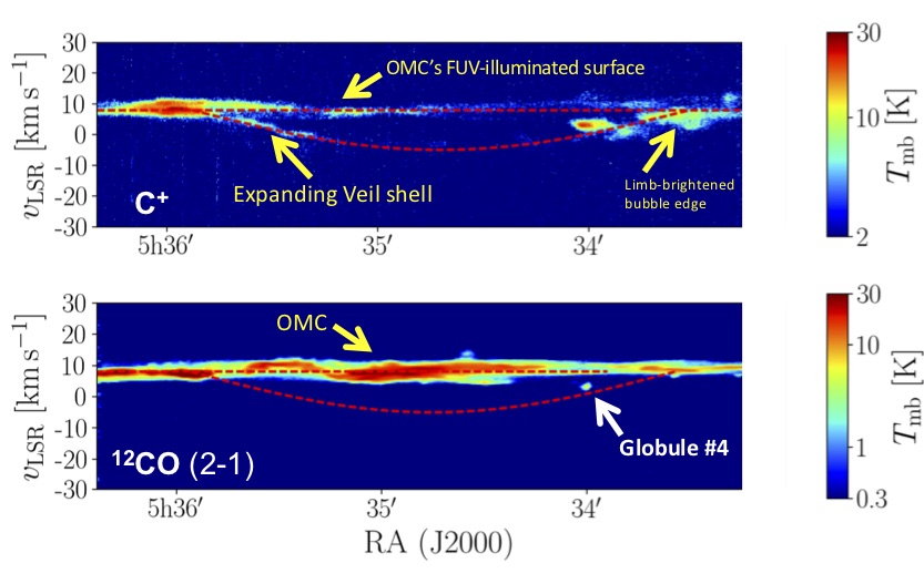
In addition, the [C ii] 158 m spectra reveal fainter components that are blueshifted from OMC-1 velocities and reach negative LSR velocities (see the spectra in Fig. 5). Goicoechea et al. (2015) already found that 15 % of the [C ii] 158 m luminosity toward the central regions of OMC-1 does not arise from its UV-illuminated surface. This C+ emission mainly comes from the foreground half-shell that surrounds OMC-1 and expands (toward us) at 13 km s-1 (Pabst et al., 2019, 2020). The relatively narrow [C ii] 158 m line profiles (v 4 km s-1) in the shell demonstrate that the gas is largely neutral. That is, dominated by H, H2, and C+ (with an ionization potential of 11.3 eV). Indeed, hydrogen recombination lines from fully ionized H ii regions display much broader profiles (v 15 km s-1 for 5,000 K; Churchwell et al., 1978). However, carbon recombination lines from the surface and edges of OMC-1, detected at radio (Natta et al., 1994; Salas et al., 2019) and millimeter wavelengths (Cuadrado et al., 2019), show narrow profiles v = 2.5-5 km s-1. These are typical of the neutral photodissociation region (PDR) that separates the hot H ii gas from the cold molecular gas. The 8 m emission from UV-pumped PAHs also arises from PDR gas (e.g., Hollenbach & Tielens, 1997). Hence, the good correlation between the C+ and PAH emission from the shell (Pabst et al., 2019), together with the narrow [C ii] 158 m line-widths, supports the conclusion that most of the C+ emission in the shell originates from neutral PDR gas rather than in the ionized gas.
3.1 Detection of blue-shifted CO globules in the Veil
The dotted rectangular box in Fig. 1 shows the specific area investigated in this work (expanded in Fig. 3). Despite the 0.75 K km s-1 (3) sensitivity level of our 12CO (2-1) map, equivalent to (12CO) (5-15)1014 cm-2, we do not detect widespread and extended CO emission from the shell (i.e., blueshifted from the OMC). For the typical extinction ( 1-2 mag) and plausible gas densities ( of several 103 cm-3) in this material (O’Dell, 2001; Abel et al., 2016), UV photodissociation must severely restrict the formation of abundant CO (van Dishoeck & Black, 1988). Nevertheless, the lack of detectable extended CO emission does not directly imply that the whole shell is 100% atomic throughout and not molecular.
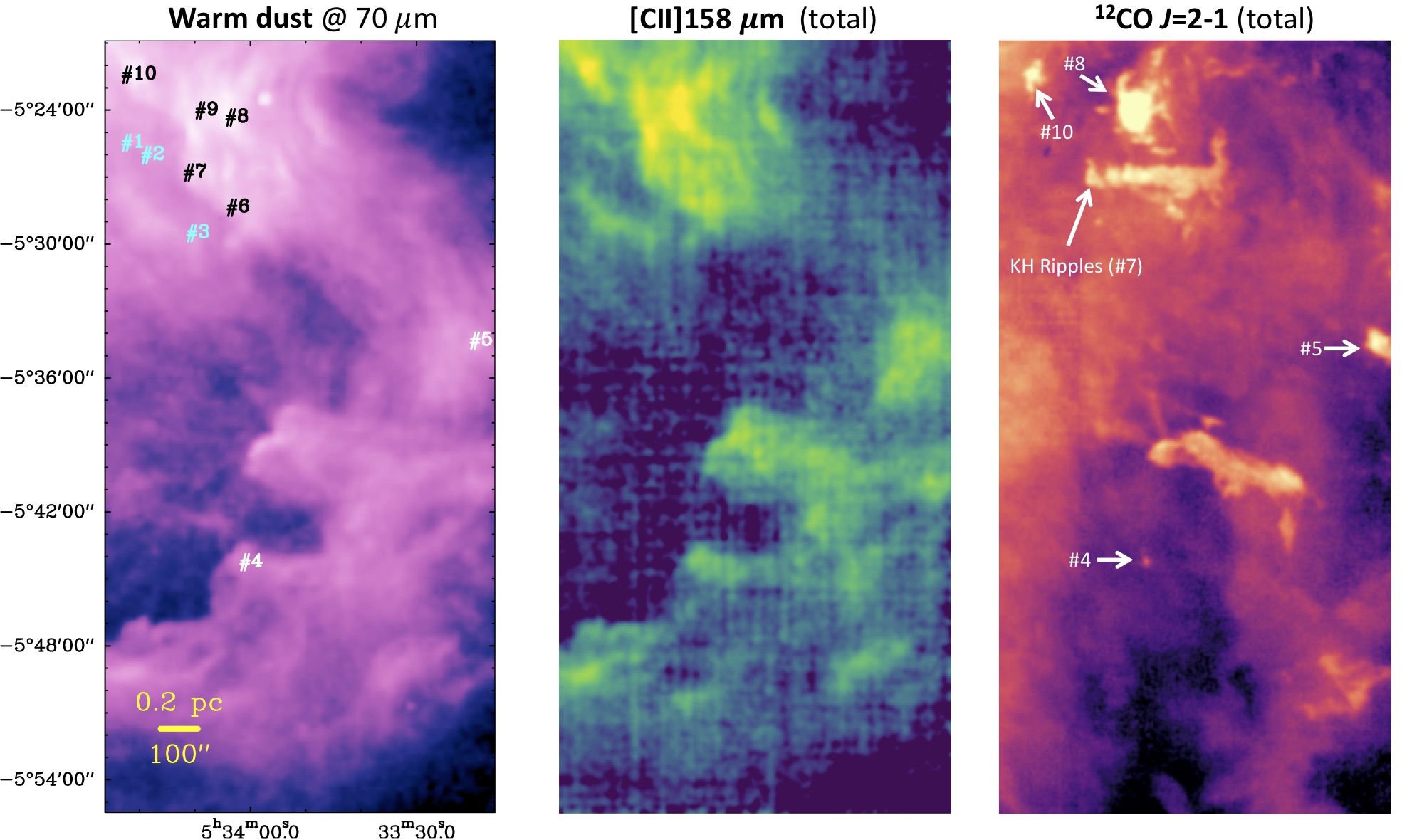
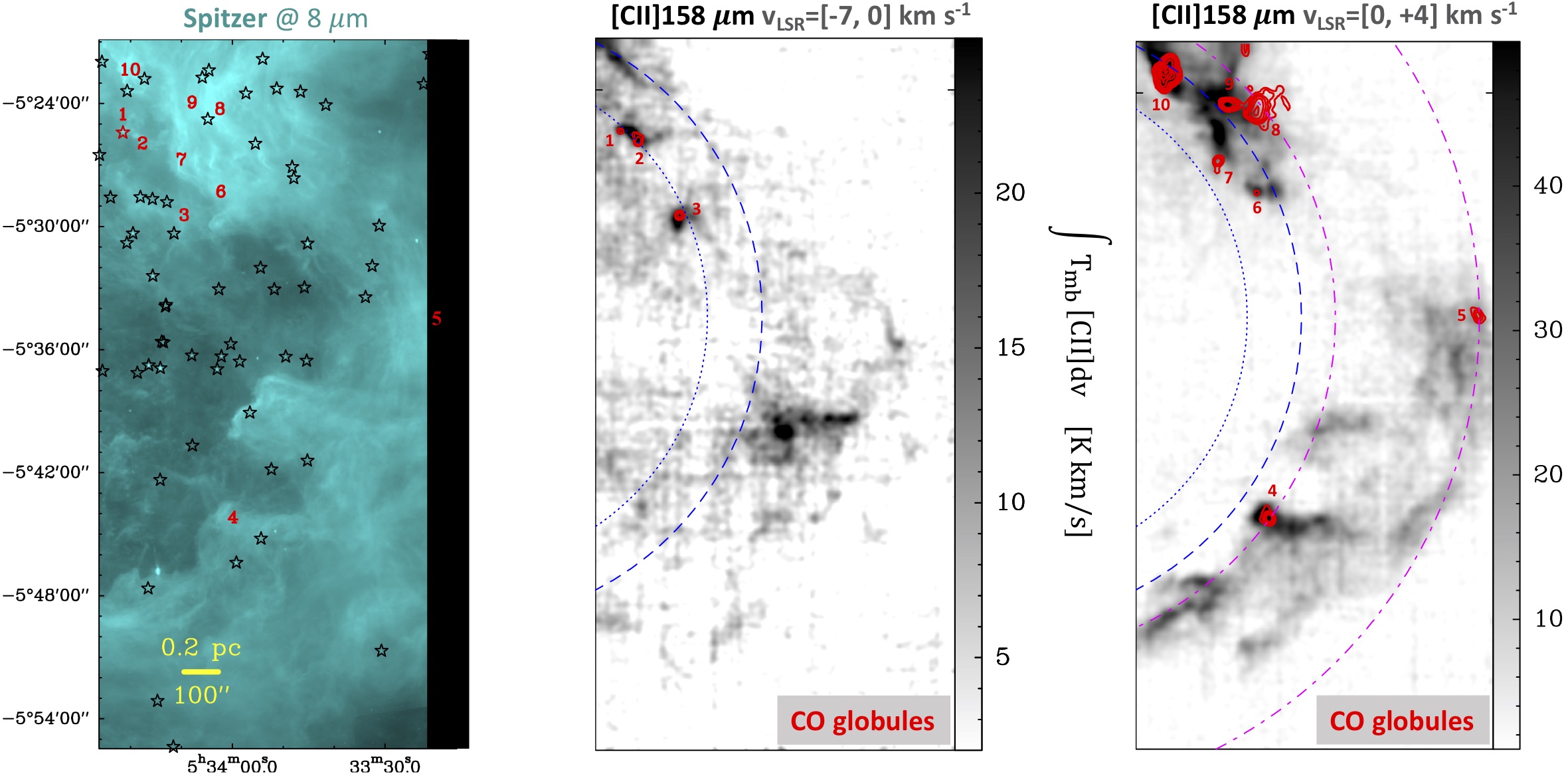
Indeed, Fig. 4 shows the presence of globules and other CO emission structures blueshifted from the OMC. This includes the first detection of quiescent molecular gas at negative vLSR (#1, #2, and #3) and well separated from the main star-forming cores in the integral-shape filament (Johnstone & Bally, 1999; Kirk et al., 2017). We extracted the angular sizes of these globules using the native CO maps at 11′′ resolution. They range from 18′′ (7,500 AU) to 80′′ (0.16 pc), with their fainter emission contour typically above 5.
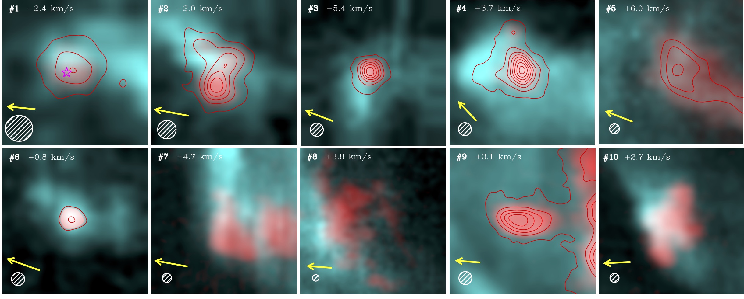
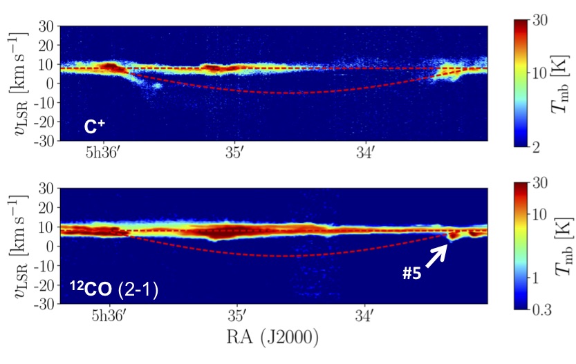
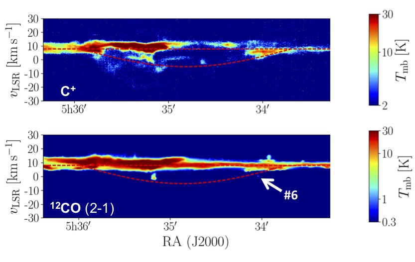
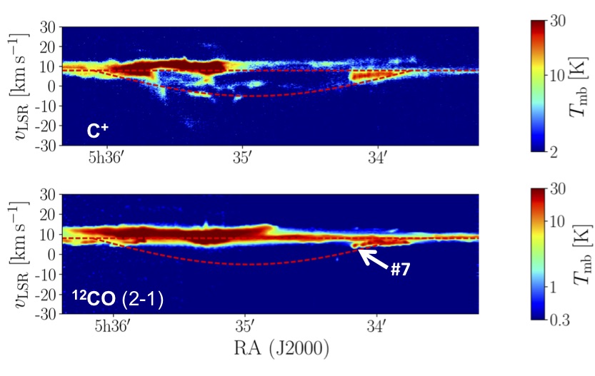
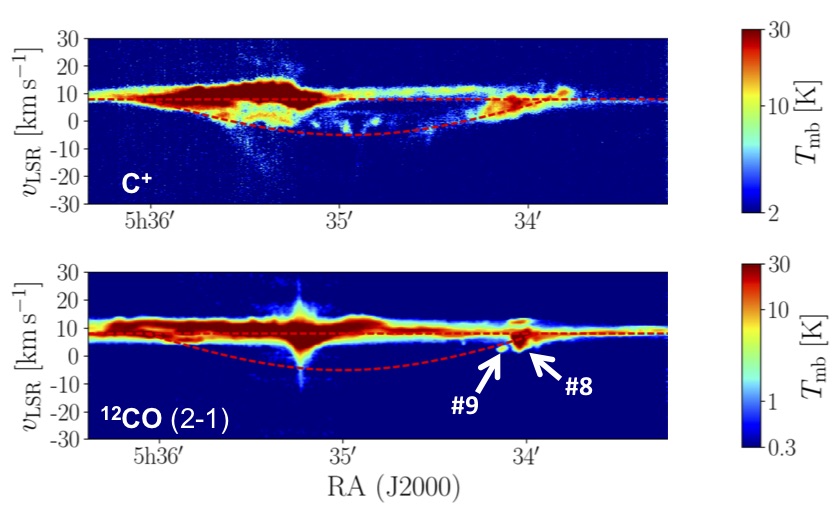
Figure 6 shows a gallery with zooms on the globules and other blueshifted structures in the CO (2-1) (reddish) and 8 m band (bluish) emission. Figure 11 of the Appendix shows the same gallery but displaying the [C ii] 158 m emission (bluish) integrated in exactly the same velocity range as the CO emission from each globule (i.e., C+ that is strictly connected in velocity with CO). The smallest globules (#1, #2, #3, and #6) resemble the kind of tiny clouds originally seen in visible plates against the nebular emission from H ii regions (ionized by radiation from nearby OB stars) and referred to as “globules”222Interestingly, no globule associated with the Orion nebula was found in the original work of Bok & Reilly (1947). (Bok & Reilly, 1947; Minkowski, 1949; Thackeray, 1950), “cometary globules”, or “tear drops” (Herbig, 1974), and more recently “cusps” (De Marco et al., 2006) or “globulettes” when their sizes are smaller than about 10,000 AU (Gahm et al., 2007). Hence, in this work we use the term “globule” in a generic sense to signify small and over-dense molecular gas blobs. Globules #1, #3, and #6 show spherical morphologies but they are surrounded by extended 8 m (and [C ii] 158 m) emitting structures. Globules #2 and #4 are also roundish, but show indications of diffuse tails. These globules have CO velocity centroids that are significantly blueshifted from OMC and are isolated.

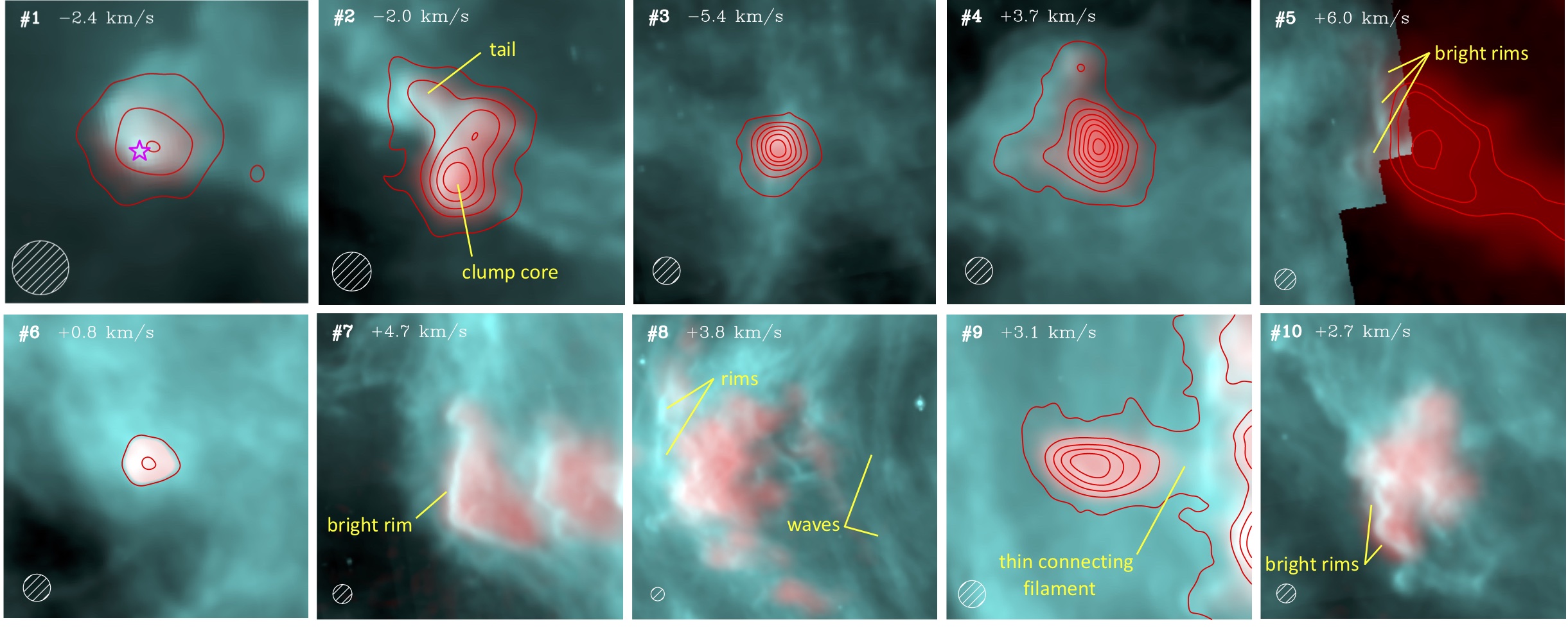
In addition, previous CO maps of OMC reveal more extended and peculiar structures (Shimajiri et al., 2011; Berné et al., 2014; Kong et al., 2018). Some of our blueshifted but positive-vLSR globules belong to these structures. They are located close to the surface of the dense molecular cloud (but are likely of a different nature) or at the limb-brightened edge of the shell. A very remarkable structure of this kind is the Kelvin–Helmholtz (KH) “ripples” or “periodic undulations” studied by Berné et al. (2010) and indicated in our Figs. 2 and 3. Globule #7 is the blueshifted head of the KH ripple, whereas #5 in the westernmost part of the map is the tip of a more prominent and bright-rimmed structure, a pillar or ”elephant trunk” that points toward the Trapezium. The extended structures associated with #5, #8 and #10 also show multiple far-UV (FUV; 13.6 eV) illuminated edges revealed by their bright 8 m rims delineating the CO emission. These globules must be facing strong FUV fluxes. Globule #8 has a different morphology. It is part of a more extended region that is apparently connected to the OMC, and is characterized by wavelike structures and 8 m rims pointing toward the Trapezium. The CO and [C ii] 158 m emission follows an arched morphology also roughly pointing toward the Trapezium. Finally, globule #9 appears to be detached from #8, still showing a thin connecting filament.
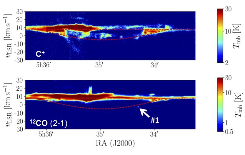
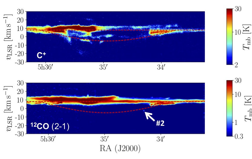
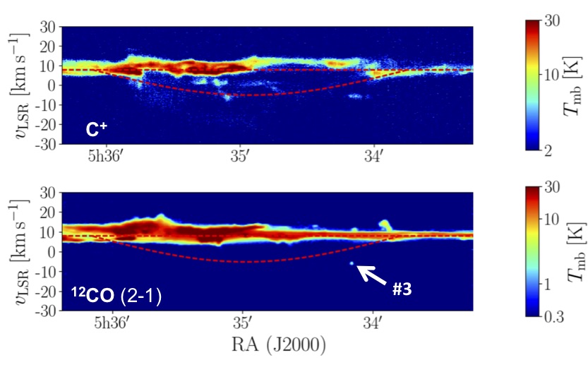
The similar velocity centroid of the CO and [C ii] 158 m lines toward each globule (Table 5), as well as the spatial coincidence with velocity-coherent C+ extended emission structures indicate that several globules are embedded in the shell (see position–velocity diagrams in Fig. 7 and Figs. 12 to 19). Owing to the shell expansion, the negative-vLSR globules should be located in the near side of the shell (closer to us) and not at the surface of the OMC. These globules resemble starless cores embedded in a C+-bright envelope (for globule #4 with the morphology of the [C ii] 158 m emission akin to a cometary globule, Fig. 4). Despite their relatively faint 12CO emission levels, we also detect 13CO toward most of them. However, with the exception of globules #5 and #10, we do not detect blueshifted C18O emission. The lack of C18O (2-1) emission is consistent with low extinction depths in the range of AV 3 mag (Frerking et al., 1982; Cernicharo & Guelin, 1987; Pety et al., 2017).
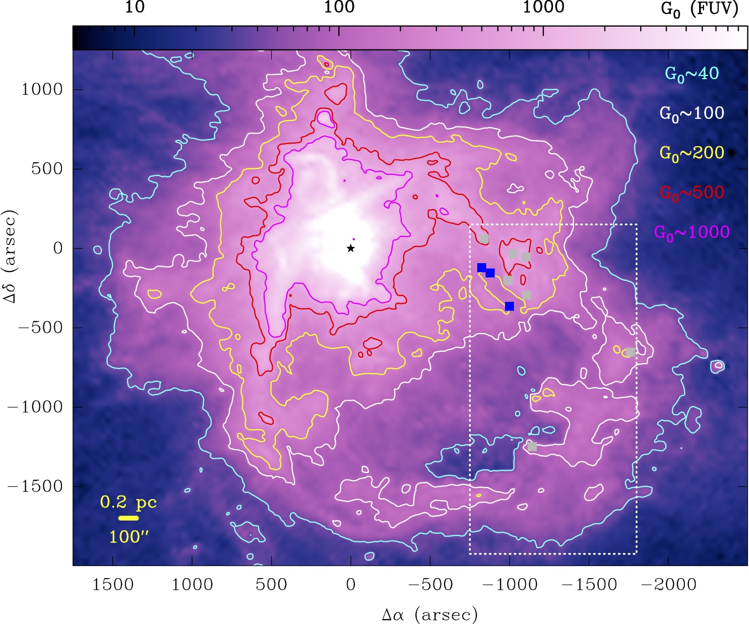
To conclude this general presentation and analysis of the region, in Fig. 8 we show the approximate map of , the stellar FUV flux in the line of sight toward the bubble ( 1.7 is the mean radiation field in the solar neighborhood in Habing units; Habing, 1968). These FUV photons heat grains, ionize C atoms, and dissociate CO molecules. Figure 8 shows that the innermost regions of the shell are directly exposed to FUV radiation from the Trapezium stars at levels of several hundred. The FUV flux reaching the outer portions of the shell is more attenuated, down to 40 (see Sect. 4.3 for details).
3.2 Observed line parameters of the CO globules
The 12CO (2-1) line profiles are relatively narrow, with a median value of v(12CO) = 1.5 km s-1. These profiles are remarkably Gaussian (except for #5 and #8 that display blended components) and do not show the kind of line asymmetries or wings expected in collapsing, or expanding, or outgassing globules. The velocity centroid of both 12CO and 13CO lines coincides for each globule (both species arise from the same gas component). However, the 13CO (2-1) lines are narrower, that is, v(13CO) = 1.2 km s-1 (median), indicating that the 12CO (2-1) lines are opacity-broadened (Phillips et al., 1979). The [C ii] 158 m lines toward the globules are significantly broader, that is, v(C+) = 3.2 km s-1 (median), and show more intricate line profiles. Assuming =100 K for the C+ gas (Pabst et al., 2019), =10 K for 13CO, and separating the thermal broadening ((C+) = 0.26 km s-1 and (13CO) = 0.05 km s-1), the differences in observed line widths imply that the [C ii] 158 m emission arises from a more turbulent gas that surrounds the 13CO cores, with (C+)/(13CO) 1.3/0.5 (vobs = 2.35 and = +). These dispersions imply transonic to supersonic motions (see Table 2 for each globule).
| Coordinates | (CO)a | (CO)b | (CO) | c | d | ||
|---|---|---|---|---|---|---|---|
| globule | (Ra. Dec.) | (AU) | (K) | (cm-2) | (10-5 adopted) | (104 cm-3) | (mag) |
| #1 | 5h34m21.21s - | 3,700 | 7.60.6 | (3.80.5)1016 | 1.50.5 | 4.82.8 | 1.91.1 |
| #2 | 5h34m17.65s - | 7,000 | 10.00.9 | (same as #1) | 1.50.5 | 2.51.5 | 1.91.1 |
| #3 | 5h34m09.55s - | 5,800 | 13.81.4 | (3.80.2)1016 | 1.50.5 | 3.01.6 | 1.81.0 |
| #4 | 5h33m59.86s - | 8,300 | 19.82.2 | (3.80.1)1016 | 1.50.5 | 2.11.1 | 1.80.9 |
| #5 | 5h33m18.44s - | 7,500 | 46.26.0 | (1.80.2)1018 | 15.05.0 | 10.96.1 | 8.54.8 |
| #6 | 5h34m02.27s - | 3,100 | 7.90.6 | (2.80.3)1016 | 1.50.5 | 4.32.5 | 1.40.8 |
| #7 | 5h34m10.00s - | 6,200 | 46.46.1 | (5.80.5)1017 | 15.05.0 | 4.32.4 | 2.81.6 |
| #8 | 5h34m02.46s - | 16,600 | 34.44.4 | (3.00.3)1017 | 15.05.0 | 0.90.5 | 1.50.8 |
| #9 | 5h34m07.99s - | 7,200 | 31.84.0 | (1.40.1)1017 | 15.05.0 | 0.90.5 | 0.70.4 |
| #10 | 5h34m20.14s - | 14,500 | 58.07.9 | (1.50.2)1018 | 15.05.0 | 4.72.7 | 7.64.6 |
| Median | 7,100 | 25.8 | 8.61016 | 8.32.8 | 3.6 | 1.8 |
4 Analysis
Wide-field near-IR and visible images of H ii regions allow the detection of globules of neutral gas and dust in their surroundings (e.g., De Marco et al., 2006; Gahm et al., 2007). Detected in silhouette or as bright cusps, photometric images reveal the morphology and projected position of these compact objects. Velocity-resolved C+ and CO spectroscopic images (at sub-km s-1 resolution) help to find these globules in velocity space, and also provide a means of quantifying their physical conditions, bulk masses, and gas kinematics.
A few studies of this kind have previously focused on small CO globules seen in planetary nebulae around evolved stars such as the Helix Nebula (e.g., Huggins et al., 1992, 2002) and on CO globules seen toward H ii regions in more distant high-mass star-forming regions such as the Rosette Nebula (Schneps et al., 1980; Gonzalez-Alfonso & Cernicharo, 1994; Dent et al., 2009; Gahm et al., 2013) located at a distance of 1.6 kpc. In this section, we analyze the [C ii] 158 m, 12CO, and 13CO emission from the globules detected in Orion at high spatial resolution.
4.1 Single-slab analysis
With the detection of a single rotational line, and given the possible small-scale structure and potential gradients in the physical conditions of these globules, the derivation of their gas density, temperature, and mass is not trivial. In this section, we assume that the CO level populations are characterized by a single excitation temperature (i.e., single-slab analysis). Given the low critical densities for collisional excitation of the observed CO lines ( 104 cm-3), we implicitly assume that the 12CO levels are close to thermalization ( ) and that 13CO is a good tracer of the total molecular column density. This is obviously a first-order approach (e.g., at low densities the higher- lines will be subthermally excited) but it is highly complementary to the mere photometric detection of these globules. In Sect. 4.4 we perform a more detailed depth-dependent modeling.
The observed (12CO)/(13CO) integrated line intensity ratio toward all globules is always lower than 25 (with = in K km s-1; see Fig. 20 in the Appendix). This is lower than the 12C/13C isotopic ratio () in OMC-1 (=673; Langer & Penzias, 1990) and implies that: the 12CO emission is optically thick, the 13CO abundance is enhanced over the expected isotopic ratio, so-called chemical fractionation (Langer et al., 1984), or both. For optically thick lines, the 12CO (2-1) excitation temperature is a good lower limit on , and we can directly extract this from the line peak temperature, , of each globule (see Table 4):
| (1) |
where is the equivalent brightness temperature of a black body at , and is the cosmic background temperature 2.7 K. We note that we spatially resolve these globules, and so no beam-filling factor correction is needed. Taking into account that (13CO 2-1) = (12CO 2-1), where 1, we can determine the opacity of the 13CO (2-1) line, = ln (1, from observations, and also the 13CO column density:
| (2) |
where is the 13CO column density (in cm-2) in the limit (see eq. 3). The factor reflects the possible different excitation temperatures of 12CO (2-1) and 13CO (2-1) lines due to line-trapping effects as the 12CO (2-1) line opacity increases. The parameter tends to 1 in collisionally excited optically thin gas. We carried out nonlocal thermodynamic equilibrium (NLTE) calculations that show that line-trapping reduces for optically thick 12CO emission (roughly above (12CO) of a few 10cm-2) and at low (H2) densities (typically lower than 104 cm-3, the critical density of the =2-1 transition). For the expected gas densities and (CO) in these globules, we find 0.9 and this is the factor we use here. We calculate (13CO) assuming a Boltzmann distribution of the level populations at a uniform . In this case,
| (3) |
where is the 13CO (2-1) line integrated intensity for each globule (values tabulated in Table 5).
We derive the 12CO column density as (12CO)=CO), and the column density of gas across each CO globule core, = (H)+2(H2), defined as = (12CO)/(12CO). Supported by our more detailed photochemical modeling (following section), we estimate the extinction () through each globule and their mass () adopting a plausible range of (uniform) CO abundances. We use (12CO) = (0.5-1.5)10-5 when (12CO) 51016 cm-2 (the most translucent case) and (12CO) = (0.5-1.5)10-4 otherwise.
In order to determine , we use the observed angular sizes of each globule. Table 1 summarizes the radius () of each globule, and the range of gas densities ( / 2) and molecular core depths (defined as = 3.510-22 (12CO)/(12CO), see Sect. 4.4) derived in the single-slab approximation.
In this approach, the most critical error parameter in the calculated values is the adopted range of CO abundances. The adopted (12CO) range (within a factor of three) roughly agrees with specific PDR models adapted to the UV illuminating conditions in the shell (see Sect. 4.4). The resulting range of calculated values in each globule brackets the extinction values we obtain from the more detailed PDR models as well. They are also consistent with the nondetection of C18O emission, which approximately implies 3 mag for all globules (except for the globules #5 and #10).
Taking into account the achieved rms sensitivity of our maps, we also computed the minimum beam-averaged 12CO column density, (12CO), that we could have detected. We adopt with =0.25 K (the rms noise level of our native map), v=0.25 km s-1 (the velocity channel resolution), v=2 km s-1 (the expected line-width). This leads to =0.75 K km s-1. For =5-20 K, our map is sensitive to a beam-averaged (12CO) (5-15)1014 cm-2 (3). Assuming a typical shell thickness of 1.8 mag of visual extinction in the Veil (O’Dell, 2001), this limit is equivalent to detecting (12CO) abundances above (1-3) in the shell. This threshold seems high, but we highlight the strong UV illumination conditions and low extinction depth of this foreground component (i.e., low molecular column densities). On the other hand, the (12CO) column we detect toward the negative-vLSR globules is at least 25 times higher than (12CO). This implies that widespread and abundant CO is largely absent from the shell.
| (C+) | (C+)a | (C+)a | b | b | ()c | ||||
|---|---|---|---|---|---|---|---|---|---|
| globule | (km s-1)a | (106 cm-3 K) | (106 cm-3 K) | (km s-1) | (106 cm-3 K) | (106 cm-3 K) | () | ()c,d | ()e |
| #1 | 2.3(0.3) | 42.224.5 | 4.82.8 | 0.5(0.2) | 3.82.2 | 0.40.2 | 0.080.05 | 0.030.01 | 3.0(2.4) |
| #2 | 2.8(0.2) | 33.019.8 | 2.51.5 | 0.5(0.1) | 1.81.1 | 0.30.2 | 0.30.2 | 0.060.03 | 5.1(3.4) |
| #3 | 1.0(0.1) | 5.32.8 | 3.01.6 | 0.5(0.1) | 1.81.0 | 0.50.3 | 0.20.1 | 0.20.1 | 3.6(0.6) |
| #4 | 1.0(0.1) | 3.51.8 | 2.11.1 | 0.5(0.1) | 1.50.8 | 0.50.3 | 0.40.2 | 0.60.3 | 6.3(1.0) |
| #5 | 2.5(0.1) | 117.465.6 | 10.96.1 | 0.9(0.1) | 22.112.4 | 5.43.5 | 1.50.8 | 0.70.4 | 15.5(1.5) |
| #6 | 1.1(0.1) | 9.45.4 | 4.32.5 | 0.5(0.2) | 3.31.9 | 0.40.3 | 0.050.03 | 0.060.03 | 2.4(1.2) |
| #7 | 1.5(0.1) | 15.68.7 | 4.32.4 | 0.4(0.1) | 2.41.4 | 2.11.4 | 0.30.2 | 1.80.9 | 3.7(2.0) |
| #8 | 1.2(0.2) | 2.21.2 | 0.90.5 | 0.4(0.1) | 0.40.2 | 0.30.2 | 1.20.7 | 2.51.2 | 8.4(5.1) |
| #9 | 1.0(0.1) | 1.60.9 | 0.90.5 | 0.6(0.1) | 0.80.4 | 0.30.2 | 0.110.06 | 2.41.2 | 7.0(1.0) |
| #10 | 2.0(0.1) | 33.419.2 | 4.72.7 | 0.5(0.1) | 3.72.1 | 3.02.0 | 4.72.7 | 2.11.1 | 12.3(1.9) |
| Median | 1.3 | 12.5 | 3.6 | 0.5 | 2.1 | 0.4 | 0.3 | 0.6 | 5.6 |
4.2 Globule velocity dispersions, pressures, and masses
Table 2 summarizes the properties of the interior of each globule (as traced by 13CO) and of their envelope and/or surroundings (as traced by C+). This table displays the nonthermal (turbulent) and thermal gas pressures, the estimated Bonnor-Ebert mass for a pressure-confined isothermal sphere (; Ebert, 1955; Bonnor, 1956), and the Jeans mass (; e.g., Larson, 1978). To derive these masses, we assume =(12CO 2-1) and use:
| (4) |
from Lada et al. (2008), where is the temperature-dependent speed of sound inside the globule. For the Jeans mass we use:
| (5) |
from Kirk et al. (2017), where includes the dominant nonthermal support inside each globule (from 13CO line-widths). The resulting median values of the sample are = 0.3 , = 0.6 , and 5.6 (see Table 2 individually).
4.3 Stellar FUV photon flux () toward the shell
In Goicoechea et al. (2015, 2019) we estimated in OMC-1 from the integrated far-IR (FIR) dust thermal emission observed by Herschel. When dust grains absorb FUV photons, they are heated up, and re-radiate at FIR wavelengths. For a face-on PDR:
| (6) |
from Hollenbach & Tielens (1997), where is the FUV radiation field in Habing units (1.610-3 erg s-1 cm-2; Habing, 1968), and is a characteristic dust temperature in the PDR (Hollenbach et al., 1991). In practice, the longer wavelength submillimeter (submm) dust emission toward the lines-of-sight of large column density may not only be produced by FUV-heated grains but may have a contribution from colder dust in the background molecular cloud. The emission from FUV-irradiated warm dust is more easily detected at shorter FIR wavelengths. Indeed, the shell morphology in the PAH 8 m and PACS 70 m emission is very similar and nicely delineates the expanding shell. However, the bubble morphology is less apparent at longer submm wavelengths. Hence, to create an approximate map of along the line of sight toward the shell, shown in Fig. 8, we used:
| (7) |
where is the 70 m dust surface brightness in MJy sr-1. We obtained this scaling after determining from SED fits toward the irradiated surface of OMC-1 (Goicoechea et al., 2015). Because photometric observations detect the dust continuum emission projected in the plane of the sky, it is not easy to resolve the dust temperature (or ) gradient along each line of sight. Hence, the contours shown in Fig. 8 should be understood as the maximum FUV flux that can impinge a globule located in a given position sightline. The minimum value 40 (or 25 K) is representative of the most distant shell edges far from the Trapezium. This value likely represents the local FUV flux around the negative-vLSR globules.
| Model parameter | Value | Note |
| Local | 40 Habing | Best model |
| Total depth | 1.8 mag | |
| Gas density | 2104 cm-3 | |
| Cosmic Ray | 10-16 H2 s-1 | |
| = / | 5.5 | Orionb |
| / | 2.861021 cm-2 mag-1 | Orionb |
| 100 | Local ISM | |
| Abundance O / H | 3.210-4 | |
| Abundance 12C / H | 1.510-4 | Orionc |
| Abundance N / H | 7.510-5 | |
| Abundance S / H | 1.510-5 | |
| 12C / 13C | 67 | Oriond |
| Species | Predicted (cm-2) | |
| C+ | 3.51017 | Best model |
| 12CO | 5.21015 | Best model |
| 13CO | 1.81014 | Best model |
| Predicted | Observed | |
| Line | (K km s-1) | (K km s-1) |
| [C ii] 158m | 32.3 | 29.3†6.0‡ |
| 12CO (2-1) | 10.8 | 9.5†4.3‡ |
| 13CO (2-1) | 0.4 | 0.7†0.3‡ |

4.4 Depth-dependent globule photochemical models
In this section we go beyond the single-slab analysis and model the possible abundance and temperature gradients across a FUV-irradiated globule. We use the Meudon PDR code (Le Petit et al., 2006) to model the penetration of FUV radiation (Goicoechea & Le Bourlot, 2007), thermal balance (Bron et al., 2014), steady-state gas chemistry, and NLTE [C ii] 158 m, 12CO, and 13CO excitation and radiative transfer (Gonzalez Garcia et al., 2008). We adopted an extinction-to-color-index ratio, , of 5.5 (consistent with the flatter extinction curve observed in the material toward the Trapezium stars in Orion, Lee, 1968; Cardelli et al., 1989), and a / ratio of 3.510-22 mag cm2 appropriate for the material in Orion’s Veil (e.g., Abel et al., 2016, 2019). The adopted model parameters and elemental abundances are tabulated in Table 3.
The chemical network includes specific 13C isotopic fractionation reactions (Langer et al., 1984) meaning that the 13CO predictions are accurate. In FUV-irradiated gas reaction 13C+ + CO C+ + 13CO + (1) (where =35 K is the zero-point energy difference between the species on either side of the reaction, Watson et al., 1976) transfers 13C+ ions and makes 13CO more abundant than the 12CO/ ratio if reaches 50 K and below (e.g., Röllig & Ossenkopf, 2013).
In our models, one side of the globule is illuminated by 40. The other side of the globule is illuminated by = 1.7. Starting around the extinction depths and column densities estimated from the single-slab analysis, we varied the local flux of FUV photons impinging the globule, the gas density (first assumed to be constant), and (the depth into the CO globule in magnitudes of visual extinction), and tried to fit the observed [C ii] 158 m, 12CO (2-1), and 13CO (2-1) line intensities. Best model parameters and line emission predictions for the negative-vLSR globules are shown in Table 3.
The best-fit parameters to the observed line emission from the negative-vLSR globules (#1, #2, and #3) are: 40, 2104 cm-3, and 1.8 mag, giving a spatial size of 2.51017 cm = 8,300 AU 2 . This length scale approximately agrees with the observed radii of these globules. We note that an isobaric model (constant thermal pressure and varying density) with 106 cm-3 K and 50 predicts roughly the same intensities as the above constant density model. This thermal pressure is a good compromise between the values of (C+) and (the internal globule pressure) inferred in the single-slab approximation (Table 2). We note that in these models is the local FUV flux around the globule needed to reproduce the observed line intensities, whereas the map in Fig. 8 shows the integrated FUV flux along the line of sight. The lower local values are consistent with the fact that these globules are embedded in neutral gas and dust that attenuates the FUV photon flux irradiating the shell.
The abundance, gas temperature, column density, and line emissivity profiles predicted by the constant density model are shown in Fig. 9 (left). Figure 21 specifically compares the predicted and observed line intensities for the negative-vLSR globules individually. These, and also the small globule #6 (which is close in LSR velocity and shows similar emission properties), can be fitted within a factor three of the estimated local value (40), and within a factor three of the estimated gas density ( = 2104 cm-3). This density is up to 10-40 times higher than the density in the most common portions of the expanding shell, which do not show CO emission (see Abel et al., 2019, for their component III(B) of the Veil associated with the neutral shell).
As observed, our PDR models of the negative-vLSR globules predict that the C+/CO abundance ratio throughout the globule is above one, with a maximum abundance (CO) of several 10-6. Also, as observed, the model predicts an enhancement of the 13CO column density produced by isotopic fractionation. Indeed, close to the CO abundance peak (at about = 1.5 mag for this combination of and values) the gas temperature drops to 50 K and reaction (1) becomes the dominant formation route for 13CO. This chemical effect favors the overproduction of 13CO and explains the detected 13CO (2-1) emission from the globules but no [13C ii] emission (S. Kabanovic, Priv. Comm.).
A few of the brighter positive-vLSR globules show much brighter 8 m, [C ii] 158 m, and 12CO (2-1) emission levels (Table 5), up to 100 K km s-1 (see globules #5 and #10 and their 8 m and [C ii] 158 m bright rims). These are compatible with PDR models of higher FUV irradiation doses ( 500, i.e., globules that are more exposed to the unattenuated radiation field from the Trapezium), higher gas densities ( 4104 cm-3), and higher extinction depths ( 5 mag). These higher and values are consistent with our detection of C18O (2-1) line emission only toward globules #5 and #10.
Finally, the right panels in Fig. 9 are PDR models for a representative position in the Veil shell where CO is not detected. We chose = 200, = 3103 cm-3 and = 1.8 mag (e.g., Abel et al., 2016, 2019). The predicted C+ column density ((C+) 1018 cm-2) and [C ii] 158 m line intensity (50 K km s-1) are in line with the values typically observed across the shell (Pabst et al., 2019, 2020). However, the predicted CO column density is very low, (CO) 41013 cm-2 (most carbon is in the form of C+), and the expected 12CO (2-1) line intensity (0.08 K km s-1) is too faint to be detected. We conclude that owing to the strong stellar FUV irradiation conditions, most of the translucent gas in the shell will typically have exceedingly low CO column densities.
5 Discussion
5.1 Fraction of the shell mass traced by CO globules
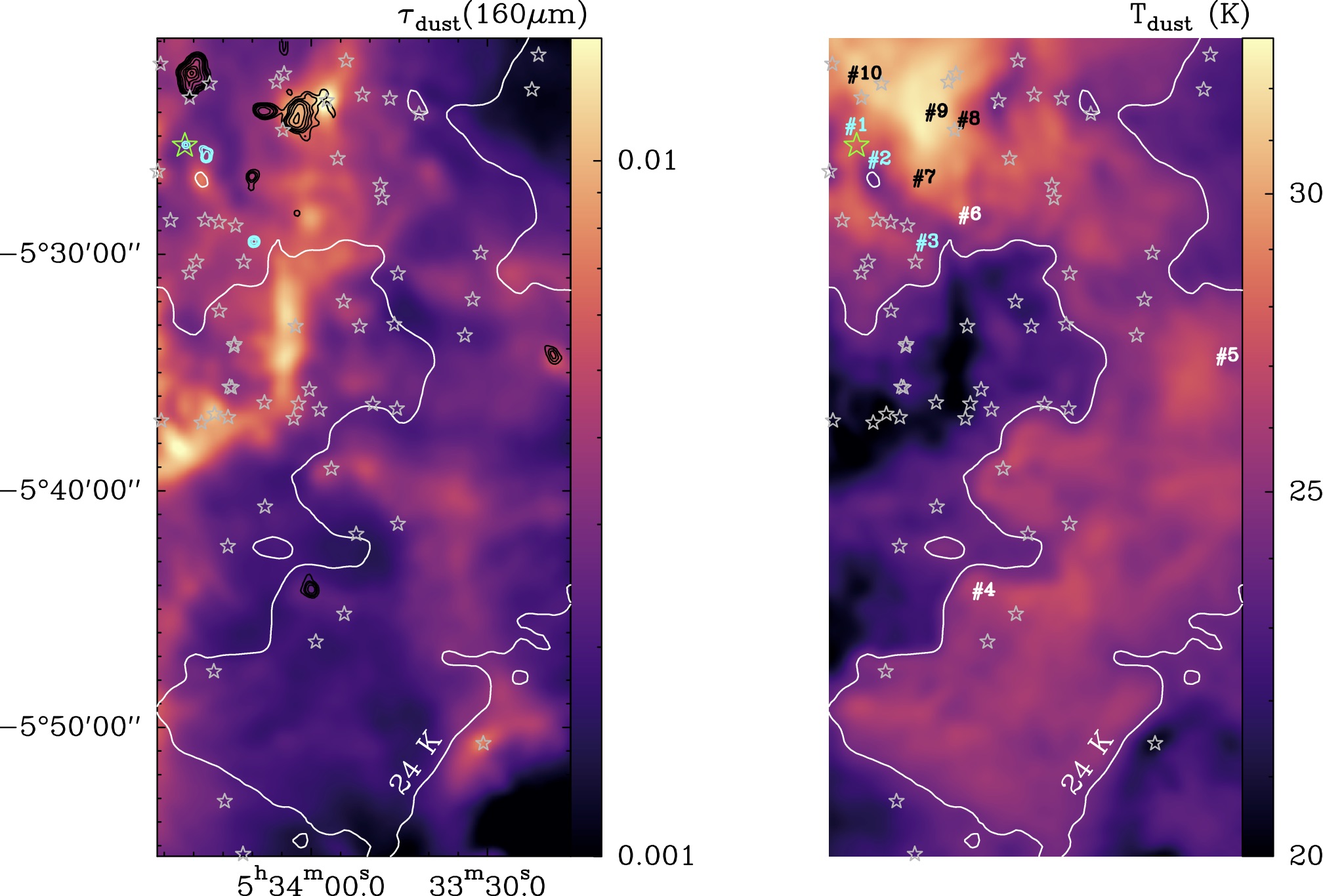
In Pabst et al. (2019, 2020), we estimated the total mass of the expanding half-shell 1,500 - 2,600 (from the FIR dust opacity and from the [C ii] 158 m emission itself). The region studied in the current work is about one-third of the shell and we determine that the shell mass in this area of interest is 400 - 700 . This is the mass enclosed inside the 24 K contour shown in Fig. 10 (right panel). Here, is an effective temperature obtained from a modified black body fit to the 70, 100, 160, 250, 350, and 500 m photometric emission measured by Herschel (André et al., 2010). The morphology of the area with 24 K resembles that revealed by the [C ii] 158 m, PACS 70, and PAH 8 m images that delineates the expanding shell. All CO globules lie inside the 24 K area. We compute the mass of the CO globules by considering their observed sizes (as seen in 12CO) and their column densities determined from the single-slab analysis. We derive a total mass that ranges from 4 to 14 adding their masses. Therefore, they only account for of the shell mass.
5.2 Magnetic support and external pressure confinement
The CO globules have the following median properties: radius 7,100 AU, gas density = 3.6104 cm-3, and mass = 0.3 . The observed 13CO line profiles (Fig. 5 and Table 5) imply supersonic nonthermal motions inside them, with a median turbulent velocity dispersion of (13CO) = 0.5 km s-1. Turbulent pressure dominates thermal pressure in the globules (see Table 2 for each globule individually). The [C ii] 158 m line profiles are systematically broader, indicating more extended gas flows, as well as higher turbulent velocity dispersions in their envelopes and in the interglobule medium, with a median of (C+)=1.3 km s-1. This value implies high turbulent pressures of (C+) = (with = ) around the CO globules. Their external pressure (thermal plus turbulent) is / 107 cm-3 K (median), higher than their internal pressures (/ of a few 106 cm-3 K).
Velocity-resolved HI Zeeman observations toward thin, low-density ( 103 cm-3) portions of the Veil have suggested typical (line-of-sight) magnetic field strengths of = - G, reaching = 100 G or more toward several positions (Troland et al., 2016). This latter value implies magnetic pressures of / = 8106 K cm-3 if = (Crutcher, 1999; Abel et al., 2016). Hence, the Veil seems to be a very magnetized medium, with the energy in being similar to or more than that in gas motions or gravity. In general, increases with density at ionized and molecular gas boundaries (, e.g., Planck Collaboration et al., 2016). Hence, we can expect stronger fields threading the denser CO globules. As an example, the derived intensity of the (plane-of-the-sky) magnetic field in the Orion Bar PDR is 300 G (derived from the polarized FIR dust emission; Chuss et al., 2019). In the swept-up material that confines the bubble, compression associated with the expansion of the shell itself will further increase the magnetic field as, given the high degree of ionization in PDR gas, () (C+), the field lines will be “frozen-in”. Overall, we conclude that plausible magnetic fields ( 100-200 G) would be sufficient to magnetically support the CO globules. We note that simulations do predict that FUV-irradiated cometary globules can be magnetically supported (e.g., Lefloch & Lazareff, 1994; Henney et al., 2009; Mackey & Lim, 2011).
The expanding shell is certainly massive, 1,500-2,600 (Pabst et al., 2020), comparable to the current mass of the molecular core behind (OMC-1; e.g., Genzel & Stutzki, 1989; Bally et al., 1987). The shell material has been swept up by the disruptive effects of Ori C winds and UV radiation. However, in the surveyed area, the mass of CO globules only represents 3% of the total shell mass. Assuming 40, the timescale for photodissociation of CO in the shell is considerably shorter than its expansion timescale ( 200,000 yr; Pabst et al., 2019). This is consistent with the lack of widespread and extended CO emission in the Veil and leaves the origin and fate of the detected molecular globules as an open question. We discuss this issue, at least qualitatively, in the following section.
5.3 Origin and evolution of the CO globules in the Veil
Globules may form in-situ by hydrodynamic instabilities (see e.g., Schneps et al., 1980; Sharp, 1984; Murray et al., 1993; Nakamura et al., 2006) at the interface between the (shell’s) neutral gas that rests on a light and rarefied (about 1 cm-3) hot plasma (Güdel et al., 2008). This interface is Rayleigh-Taylor unstable (Spitzer, 1954) and could form “trunks” or “fingers” of size on timescales of / 105 ( / 0.1 pc) yr (where is the speed of sound in the shell: 1 km s-1 at 100 K). The observed sizes of the CO globules, about 10% of the total shell thickness, indeed imply that they could form during the expansion of the shell into an environment of lower density ( , see e.g., Schneps et al., 1980). Kelvin-Helmholtz instabilities could also develop at the side of the fingers over similar timescales (Sharp, 1984; Murray et al., 1993; Nakamura et al., 2006; Berné & Matsumoto, 2012). Indeed, wave-like emission structures (typical of these instabilities) with spatial wavelengths ranging from 0.1 to 0.01 pc have been observed at several ionized–molecular gas interfaces in OMC-1. In particular, Berné et al. (2010) and Berné & Matsumoto (2012) analyzed the “KH ripples”, with #7 being the head of this structure (see Fig. 6 for a detailed view). Much higher resolution ALMA images of the Orion Bar PDR suggest smaller scale density undulations separated by 0.01 pc at the FUV-irradiated boundary between OMC-1 and the Huygens H ii region (Goicoechea et al., 2016).
Alternatively, the CO globules could have been pre-existing molecular structures (e.g., like in Reipurth, 1983), which are denser than the shell, and are perhaps generated by the turbulent velocity field in the OMC (e.g., Hartmann & Burkert, 2007; Hacar et al., 2017). These globules are compressed and swept along by a passing shock accompanying the expanding shell (e.g., Pikel’Ner & Sorochenko, 1974). If the initial gas density contrast between globules and shell has a value of about 10, the shock wave penetrating the CO globules will be slower by a factor of approximately three. This gives a shock velocity of vshock 4 km s-1, fast enough to traverse the globule in / vshock 10,000 yr and trigger compression. Gas cooling through CO lines will decrease the post-shock gas temperature and further enhance gas compression and density. This could result in free-fall times, , comparable to the shell expansion timescale () if globules are compressed to densities 2104 cm-3 (comparable with our estimated values). However, given the physical conditions in the Veil shell: enhanced turbulence, FUV-heating, and strong magnetic field, it may be unlikely that gravity can beat the pressure support of the globule (see further discussion in the following section).
The detected CO globules are surrounded by larger structures of predominantly neutral gas and dust, emitting thermal continuum at 70 m, PAHs, and [C ii] 158 m (that matches the velocity of the CO emission; see Fig. 11). This material likely shields the globules from extreme UV (EUV; 13.6 eV) ionizing radiation and reduces the flux of dissociating FUV photons reaching their interiors. This scenario is consistent with the observed low CO excitation temperatures (10 K) and moderate local values around the negative-vLSR globules (and #6). It is also consistent with their apparent spherical morphology (globules #1, #4 and #6). This is indicative of little active interaction with ionizing EUV photons that would have carved them into “tear drops” and less spherical shapes (e.g., De Marco et al., 2006). This would also explain why these globules survive (longer) in this harsh environment. Alternatively, some of the more roundish globules might have already lost their lower density molecular tails (e.g., Gahm et al., 2013). We find this scenario less likely for globules currently embedded in the shell, but this may be the case for globule #3 which looks more isolated in its position–velocity diagram (Fig 14) and is perhaps located outside the shell. However, the shell geometry is more complicated than the simple modeled arcs shown in the diagrams, and therefore this argument is not conclusive. In addition, and even if the detected globules in Orion are all mostly illuminated laterally, projection effects may influence their apparent morphologies (that depend on the aspect angle). In extreme cases, an elongated globule with head or tail may look spherical.
Eventually, the ionization front associated with the expanding H ii region inside the expanding bubble will encounter these globules, further sculpting, photoevaporating, and compressing them (see simulations in Henney et al., 2009). This radiative interaction will lead to a significant erosion of the globules (e.g., Bertoldi & McKee, 1990; Lefloch & Lazareff, 1994). The smallest and roundish globules may develop “cometary” or “tear drop” shapes. Still, their morphological evolution depends on the strength and orientation of the magnetic field threading them. For strong fields, simulations predict that photoevaporating globules can acquire flattened shapes (Henney et al., 2009). Only globule #9 is suggestive of this geometry.
On the other hand, the larger and more elongated CO structures at positive-vLSR (globules #5, #8, and #10) represent the first stages in the formation of (Orion-equivalent) miniature “Pillars of Creation” (e.g., Pound, 1998; Tremblin et al., 2012). Globules #5 and #8 are located at the limb-brightened edge of the shell (and their CO emission is connected to that of the background molecular cloud) whereas #10 is not at the limb and it is more isolated in velocity with respect to the OMC. These structures, and also the “KH ripples” (Berné et al., 2010), display bright 8 m and [C ii] 158 m emission rims pointing toward the Trapezium (see Figs. 6 and 11). They are also characterized by higher CO excitation temperatures (40-60 K) and higher local values (up to hundreds). Hence, they are in a more active phase of radiative shaping and new small globules may detach from them.
5.4 Low-mass star-formation in the Veil?
An intriguing question is whether this kind of small globule can form new stars of very low mass. For several of the detected globules in Orion, their external pressure seems sufficient to overcome the stability limit for Bonnor-Ebert spheres (see Table 2) and so they do not seem to be in hydrostatic equilibrium but instead to be dynamically evolving (e.g., Galli et al., 2002). However, the estimated globule masses are smaller than the Jeans mass needed for gravity to dominate and trigger collapse (Sect. 4.2). Indeed, the inferred large globule virial parameters, = / 1, the derived scaling of with their mass, , and the likely fact that all agree with theoretical expectations of pressure-confined, gravitationally unbound globules (e.g., Bertoldi & McKee, 1992; Lada et al., 2008).
Interestingly, while the dense prestellar cores in Orion’s integral-shape filament are confined by pressure due to the weight of the molecular cloud and the filament (Kirk et al., 2017), the CO globules in the Veil are mainly confined by the turbulent pressure of the wind-driven shell. This points to transient molecular globules that would ultimately be photoevaporated (e.g., Oort & Spitzer, 1955; Gorti & Hollenbach, 2002) or expand and disperse as the pressure inside the expanding shell decreases. In this likely scenario, most CO globules, and the bulk material in the shell, will not form new stars. Given the large masses swept up in the shell, this will limit the global star-formation rate in Orion.
The exception that confirms the rule is globule #1 (shown in detail in Fig. 6). Its position coincides with a known young stellar object that was classified as a pre-main sequence star with a disk and was detected in previous infrared imaging surveys of Orion (YSO #1728 of Megeath et al., 2012). This match suggests that some low-mass protostars do exist inside the shell. In these cases, their molecular cocoons were probably dense and massive enough before being engulfed by the expanding shell.
The more isolated and smaller CO globules detected in the shell are part of an interesting class of tiny molecular clouds (0.1 100 ) that are different from the bigger and more massive “Bok globules”. The latter ones usually form one or a few low-mass stars but they are mostly unrelated to H ii regions (Bok & Reilly, 1947; Reipurth, 1983; Nelson & Langer, 1999; Launhardt et al., 2010). Previous studies of small globules around the H ii region in the Rosette Nebula have suggested that they could be a source of brown dwarfs and free-floating planetary-mass objects (e.g., Gahm et al., 2007, 2013). However, our virial and Jeans mass analysis does not support this scenario for the small globules in Orion. Nevertheless, it would be interesting to carry out follow-up deep observations of these objects in higher critical-density molecular tracers able to reveal the presence of denser and more massive gas cores in their interiors.
6 Summary and conclusions
We expand previous maps of Orion A taken with the IRAM 30m telescope in the 12CO, 13CO, and C18O ( = 2-1) lines at 11′′ resolution ( 4,500 AU). We investigate a 2 pc 4 pc (600 arcmin2) region of the neutral shell that confines the wind-driven Veil bubble around the Trapezium cluster. This massive shell, which is made of swept up material from the natal Orion molecular cloud, is very bright in [C ii] 158 m, PAHs, and 70 m dust emission (Pabst et al., 2019). Owing to intense UV radiation from Ori C, the most massive O-type star in the cluster, the expected column densities of molecular gas in this extended but translucent foreground material were very low. We summarize the primary results of this work as follows:
– We find that widespread and extended CO emission is largely absent from the Veil. This implies that most of the neutral material that surrounds the Orion cluster is “CO-dark” but not necessarily 100 % atomic. In particular, we present the detection of CO globules (some of them at negative vLSR) embedded in the expanding shell that encloses the bubble.
– The CO globules are small ( 7,100 AU), moderately dense ( = 3.6104 cm-3), and have low masses: = 0.3 (median values of the sample). The observed [C ii] 158 m, 12CO, and 13CO (2-1) emission from the negative-vLSR globules (#1, #2, and #3) and also from #6, those closer to us, are reproduced by depth-dependent PDR models with 2104 cm-3 and 40 (both quantities within a factor 3). These globules show roundish morphologies. In the other extreme of the sample, structures #5 and #10 (at positive vLSR) are bigger and more elongated. Fitting their emission lines requires stronger FUV photon fluxes ( 500), higher densities ( 4104 cm-3), and higher extinction depths ( 5 mag). These values are consistent with the detection of C18O (2-1) emission from these two molecular gas structures.
– The inferred nonthermal velocity dispersions ((C+) 1.3 km s-1 and (13CO) 0.5 km s-1) indicate that the gas in the shell and in the envelopes around the globules is more turbulent and warmer ( 100 K) than in their molecular interiors ( 10–50 K). These dispersions imply transonic to supersonic motions. The ratio of the nonthermal to thermal pressure is always greater than one (and up to 10) both in the globule interiors and in their envelopes. We derive that the external pressure around the CO globules (turbulent + thermal) is high, 107 K cm-3 (median value).
– The magnetic field strength previously derived in low-density portions of the Veil and in the denser gas of the Orion Bar suggests that the CO globules in the shell can be threaded by fields of the order of 100-200 G. These values would be sufficient to magnetically support them ( . Together with the inferred large virial parameters, 1, the gathered evidence suggests pressure-confined, gravitationally unbound globules.
– The CO globules are embedded in the predominantly neutral material of the shell. They are either transient objects formed by hydrodynamic instabilities or pre-existing over-dense structures of the original molecular cloud. They are being sculpted by the passing shock associated with the expanding shell and by UV radiation from Ori C. Several of them are isolated and intriguingly roundish. This suggests that they are not being actively photo-ionized. The more elongated and warmer globules (#5, #8, and #10) likely represent the first stages in the formation of (Orion-equivalent) miniature Pillars of Creation.
– The estimated masses of all globules are lower than their Jeans masses, and thus do not imply they will easily form stars unless they accrete more mass. To break the rule, globule #1 coincides with the position of a known YSO. This suggests that some low-mass protostars do exist inside the expanding shell. One possibility is that their molecular cores were massive enough and had collapsed before being caught by the shell.
The lack of extended CO emission from the swept-up shell that encloses the Veil bubble in Orion implies that winds and UV radiation from young massive stars expel, agitate, and photo-dissociate most of the disrupted molecular cloud gas. This material is blown to large distances, far from the main star-forming cores. Large-scale turbulence and FUV heating across the shell hinders the formation of new stars. Given the large amount of disrupted material,
these feedback processes must limit the star-formation rate in Orion. M42 is certainly impressive (mostly because it is so close to us) but it is interesting to see that most of the fireworks, energetics, and gas dynamics are mostly driven by the massive stellar system Ori C.
Acknowledgements.
We acknowledge helpful comments and suggestions from our referee. We warmly thank the operators, AoDs, and chefs at the IRAM 30m telescope for their support while the CO observations were conducted. This work is also based on observations made with the NASA/DLR Stratospheric Observatory for Infrared Astronomy (SOFIA). SOFIA is jointly operated by the Universities Space Research Association, Inc. (USRA), under NASA contract NNA17BF53C, and the Deutsches SOFIA Institut (DSI) under DLR contract 50 OK 0901 to the University of Stuttgart. We acknowledge the work, during the C+ upGREAT square degree survey of Orion, of the USRA and NASA staff of the Armstrong Flight Research Center in Palmdale, the Ames Research Center in Mountain View (California), and the Deutsches SOFIA Institut. We thank the Spanish MICIU for funding support under grant AYA2017-85111-P. Research on the ISM at Leiden Observatory is supported through a Spinoza award.References
- Abel et al. (2019) Abel, N. P., Ferland, G. J., & O’Dell, C. R. 2019, ApJ, 881, 130
- Abel et al. (2006) Abel, N. P., Ferland, G. J., O’Dell, C. R., Shaw, G., & Troland, T. H. 2006, ApJ, 644, 344
- Abel et al. (2016) Abel, N. P., Ferland, G. J., O’Dell, C. R., & Troland , T. H. 2016, ApJ, 819, 136
- André et al. (2010) André, P., Men’shchikov, A., Bontemps, S., et al. 2010, A&A, 518, L102
- Bally (2008) Bally, J. 2008, Overview of the Orion Complex, ed. B. Reipurth, 459
- Bally et al. (1987) Bally, J., Langer, W. D., Stark, A. A., & Wilson, R. W. 1987, ApJ, 312, L45
- Berné et al. (2010) Berné, O., Marcelino, N., & Cernicharo, J. 2010, Nature, 466, 947
- Berné et al. (2014) Berné, O., Marcelino, N., & Cernicharo, J. 2014, ApJ, 795, 13
- Berné & Matsumoto (2012) Berné, O. & Matsumoto, Y. 2012, ApJ, 761, L4
- Bertoldi & McKee (1990) Bertoldi, F. & McKee, C. F. 1990, ApJ, 354, 529
- Bertoldi & McKee (1992) Bertoldi, F. & McKee, C. F. 1992, ApJ, 395, 140
- Bok & Reilly (1947) Bok, B. J. & Reilly, E. F. 1947, ApJ, 105, 255
- Bolatto et al. (2013) Bolatto, A. D., Wolfire, M., & Leroy, A. K. 2013, ARA&A, 51, 207
- Bonnor (1956) Bonnor, W. B. 1956, MNRAS, 116, 351
- Boreiko & Betz (1996) Boreiko, R. T. & Betz, A. L. 1996, ApJ, 467, L113
- Bron et al. (2014) Bron, E., Le Bourlot, J., & Le Petit, F. 2014, A&A, 569, A100
- Buckle et al. (2012) Buckle, J. V., Davis, C. J., di Francesco, J., et al. 2012, MNRAS, 422, 521
- Cardelli et al. (1989) Cardelli, J. A., Clayton, G. C., & Mathis, J. S. 1989, ApJ, 345, 245
- Carter et al. (2012) Carter, M., Lazareff, B., Maier, D., et al. 2012, A&A, 538, A89
- Cernicharo & Guelin (1987) Cernicharo, J. & Guelin, M. 1987, A&A, 176, 299
- Churchwell et al. (2006) Churchwell, E., Povich, M. S., Allen, D., et al. 2006, ApJ, 649, 759
- Churchwell et al. (1978) Churchwell, E., Smith, L. F., Mathis, J., Mezger, P. G., & Huchtmeier, W. 1978, A&A, 70, 719
- Chuss et al. (2019) Chuss, D. T., Andersson, B. G., Bally, J., et al. 2019, ApJ, 872, 187
- Crutcher (1999) Crutcher, R. M. 1999, ApJ, 520, 706
- Cuadrado et al. (2019) Cuadrado, S., Salas, P., Goicoechea, J. R., et al. 2019, A&A, 625, L3
- De Marco et al. (2006) De Marco, O., O’Dell, C. R., Gelfond, P., Rubin, R. H., & Glover, S. C. O. 2006, AJ, 131, 2580
- Deharveng et al. (2010) Deharveng, L., Schuller, F., Anderson, L. D., et al. 2010, A&A, 523, A6
- Dent et al. (2009) Dent, W. R. F., Hovey, G. J., Dewdney, P. E., et al. 2009, MNRAS, 395, 1805
- Ebert (1955) Ebert, R. 1955, ZAp, 37, 217
- Frerking et al. (1982) Frerking, M. A., Langer, W. D., & Wilson, R. W. 1982, ApJ, 262, 590
- Gahm et al. (2007) Gahm, G. F., Grenman, T., Fredriksson, S., & Kristen, H. 2007, AJ, 133, 1795
- Gahm et al. (2013) Gahm, G. F., Persson, C. M., Mäkelä, M. M., & Haikala, L. K. 2013, A&A, 555, A57
- Galli et al. (2002) Galli, D., Walmsley, M., & Gonçalves, J. 2002, A&A, 394, 275
- Genzel & Stutzki (1989) Genzel, R. & Stutzki, J. 1989, ARA&A, 27, 41
- Goicoechea & Le Bourlot (2007) Goicoechea, J. R. & Le Bourlot, J. 2007, A&A, 467, 1
- Goicoechea et al. (2016) Goicoechea, J. R., Pety, J., Cuadrado, S., et al. 2016, Nature, 537, 207
- Goicoechea et al. (2019) Goicoechea, J. R., Santa-Maria, M. G., Bron, E., et al. 2019, A&A, 622, A91
- Goicoechea et al. (2015) Goicoechea, J. R., Teyssier, D., Etxaluze, M., et al. 2015, ApJ, 812, 75
- Gonzalez-Alfonso & Cernicharo (1994) Gonzalez-Alfonso, E. & Cernicharo, J. 1994, ApJ, 430, L125
- Gonzalez Garcia et al. (2008) Gonzalez Garcia, M., Le Bourlot, J., Le Petit, F., & Roueff, E. 2008, A&A, 485, 127
- Gorti & Hollenbach (2002) Gorti, U. & Hollenbach, D. 2002, ApJ, 573, 215
- Gravity Collaboration et al. (2018) Gravity Collaboration, Karl, M., Pfuhl, O., et al. 2018, A&A, 620, A116
- Grenier et al. (2005) Grenier, I. A., Casandjian, J.-M., & Terrier, R. 2005, Science, 307, 1292
- Greve et al. (1998) Greve, A., Kramer, C., & Wild, W. 1998, A&AS, 133, 271
- Güdel et al. (2008) Güdel, M., Briggs, K. R., Montmerle, T., et al. 2008, Science, 319, 309
- Habing (1968) Habing, H. J. 1968, Bull. Astron. Inst. Netherlands, 19, 421
- Hacar et al. (2017) Hacar, A., Alves, J., Tafalla, M., & Goicoechea, J. R. 2017, A&A, 602, L2
- Haid et al. (2018) Haid, S., Walch, S., Seifried, D., et al. 2018, MNRAS, 478, 4799
- Hartmann & Burkert (2007) Hartmann, L. & Burkert, A. 2007, ApJ, 654, 988
- Henney et al. (2009) Henney, W. J., Arthur, S. J., de Colle, F., & Mellema, G. 2009, MNRAS, 398, 157
- Herbig (1974) Herbig, G. H. 1974, PASP, 86, 604
- Hollenbach et al. (1991) Hollenbach, D. J., Takahashi, T., & Tielens, A. G. G. M. 1991, ApJ, 377, 192
- Hollenbach & Tielens (1997) Hollenbach, D. J. & Tielens, A. G. G. M. 1997, ARA&A, 35, 179
- Huggins et al. (1992) Huggins, P. J., Bachiller, R., Cox, P., & Forveille, T. 1992, ApJ, 401, L43
- Huggins et al. (2002) Huggins, P. J., Forveille, T., Bachiller, R., et al. 2002, ApJ, 573, L55
- Indriolo et al. (2015) Indriolo, N., Neufeld, D. A., Gerin, M., et al. 2015, ApJ, 800, 40
- Johnstone & Bally (1999) Johnstone, D. & Bally, J. 1999, ApJ, 510, L49
- Kirk et al. (2017) Kirk, H., Friesen, R. K., Pineda, J. E., et al. 2017, ApJ, 846, 144
- Kong et al. (2018) Kong, S., Arce, H. G., Feddersen, J. R., et al. 2018, ApJS, 236, 25
- Krumholz et al. (2014) Krumholz, M. R., Bate, M. R., Arce, H. G., et al. 2014, Protostars and Planets VI, 243
- Lada et al. (2008) Lada, C. J., Muench, A. A., Rathborne, J., Alves, J. F., & Lombardi, M. 2008, ApJ, 672, 410
- Langer et al. (1984) Langer, W. D., Graedel, T. E., Frerking, M. A., & Armentrout, P. B. 1984, ApJ, 277, 581
- Langer & Penzias (1990) Langer, W. D. & Penzias, A. A. 1990, ApJ, 357, 477
- Larson (1978) Larson, R. B. 1978, MNRAS, 184, 69
- Launhardt et al. (2010) Launhardt, R., Nutter, D., Ward-Thompson, D., et al. 2010, ApJS, 188, 139
- Le Petit et al. (2006) Le Petit, F., Nehmé, C., Le Bourlot, J., & Roueff, E. 2006, ApJS, 164, 506
- Lee (1968) Lee, T. A. 1968, ApJ, 152, 913
- Lefloch & Lazareff (1994) Lefloch, B. & Lazareff, B. 1994, A&A, 289, 559
- Mackey & Lim (2011) Mackey, J. & Lim, A. J. 2011, MNRAS, 412, 2079
- Madden et al. (1997) Madden, S. C., Poglitsch, A., Geis, N., Stacey, G. J., & Townes, C. H. 1997, ApJ, 483, 200
- Megeath et al. (2012) Megeath, S. T., Gutermuth, R., Muzerolle, J., et al. 2012, AJ, 144, 192
- Megeath et al. (2016) Megeath, S. T., Gutermuth, R., Muzerolle, J., et al. 2016, AJ, 151, 5
- Menten et al. (2007) Menten, K. M., Reid, M. J., Forbrich, J., & Brunthaler, A. 2007, A&A, 474, 515
- Minkowski (1949) Minkowski, R. 1949, PASP, 61, 151
- Murray et al. (1993) Murray, S. D., White, S. D. M., Blondin, J. M., & Lin, D. N. C. 1993, ApJ, 407, 588
- Nakamura et al. (2006) Nakamura, F., McKee, C. F., Klein, R. I., & Fisher, R. T. 2006, ApJS, 164, 477
- Natta et al. (1994) Natta, A., Walmsley, C. M., & Tielens, A. G. G. M. 1994, ApJ, 428, 209
- Nelson & Langer (1999) Nelson, R. P. & Langer, W. D. 1999, ApJ, 524, 923
- O’Dell (2001) O’Dell, C. R. 2001, ARA&A, 39, 99
- Oort & Spitzer (1955) Oort, J. H. & Spitzer, Lyman, J. 1955, ApJ, 121, 6
- Ossenkopf et al. (2013) Ossenkopf, V., Röllig, M., Neufeld, D. A., et al. 2013, A&A, 550, A57
- Pabst et al. (2020) Pabst, C., Goicoechea, J. R., Teyssier, D., et al. 2020, A&A, submitted
- Pabst et al. (2019) Pabst, C., Higgins, R., Goicoechea, J. R., et al. 2019, Nature, 565, 618
- Penzias & Burrus (1973) Penzias, A. A. & Burrus, C. A. 1973, ARA&A, 11, 51
- Pety et al. (2017) Pety, J., Guzmán, V. V., Orkisz, J. H., et al. 2017, A&A, 599, A98
- Phillips et al. (1979) Phillips, T. G., Huggins, P. J., Wannier, P. G., & Scoville, N. Z. 1979, ApJ, 231, 720
- Pikel’Ner & Sorochenko (1974) Pikel’Ner, S. B. & Sorochenko, R. L. 1974, Sov. Ast., 17, 443
- Planck Collaboration et al. (2011) Planck Collaboration, Ade, P. A. R., Aghanim, N., et al. 2011, A&A, 536, A19
- Planck Collaboration et al. (2016) Planck Collaboration, Aghanim, N., Alves, M. I. R., et al. 2016, A&A, 586, A137
- Pound (1998) Pound, M. W. 1998, ApJ, 493, L113
- Rahner et al. (2017) Rahner, D., Pellegrini, E. W., Glover, S. C. O., & Klessen, R. S. 2017, MNRAS, 470, 4453
- Reipurth (1983) Reipurth, B. 1983, A&A, 117, 183
- Rodríguez-Franco et al. (1998) Rodríguez-Franco, A., Martin-Pintado, J., & Fuente, A. 1998, A&A, 329, 1097
- Röllig & Ossenkopf (2013) Röllig, M. & Ossenkopf, V. 2013, A&A, 550, A56
- Salas et al. (2019) Salas, P., Oonk, J. B. R., Emig, K. L., et al. 2019, A&A, 626, A70
- Schneps et al. (1980) Schneps, M. H., Ho, P. T. P., & Barrett, A. H. 1980, ApJ, 240, 84
- Schuster et al. (2004) Schuster, K. F., Boucher, C., Brunswig, W., et al. 2004, A&A, 423, 1171
- Sharp (1984) Sharp, D. H. 1984, Physica D Nonlinear Phenomena, 12, 3,IN1,11
- Shimajiri et al. (2011) Shimajiri, Y., Kawabe, R., Takakuwa, S., et al. 2011, PASJ, 63, 105
- Simón-Díaz et al. (2006) Simón-Díaz, S., Herrero, A., Esteban, C., & Najarro, F. 2006, A&A, 448, 351
- Sofia et al. (2004) Sofia, U. J., Lauroesch, J. T., Meyer, D. M., & Cartledge, S. I. B. 2004, ApJ, 605, 272
- Spitzer (1954) Spitzer, Lyman, J. 1954, ApJ, 120, 1
- Stahl et al. (1996) Stahl, O., Kaufer, A., Rivinius, T., et al. 1996, A&A, 312, 539
- Teyssier et al. (2002) Teyssier, D., Hennebelle, P., & Pérault, M. 2002, A&A, 382, 624
- Thackeray (1950) Thackeray, A. D. 1950, MNRAS, 110, 524
- Tremblin et al. (2012) Tremblin, P., Audit, E., Minier, V., & Schneider, N. 2012, A&A, 538, A31
- Troland et al. (2016) Troland, T. H., Goss, W. M., Brogan, C. L., Crutcher, R. M., & Roberts, D. A. 2016, ApJ, 825, 2
- van der Werf et al. (2013) van der Werf, P. P., Goss, W. M., & O’Dell, C. R. 2013, ApJ, 762, 101
- van Dishoeck & Black (1988) van Dishoeck, E. F. & Black, J. H. 1988, ApJ, 334, 771
- Watson et al. (1976) Watson, W. D., Anicich, V. G., & Huntress, W. T., J. 1976, ApJ, 205, L165
- Weaver et al. (1977) Weaver, R., McCray, R., Castor, J., Shapiro, P., & Moore, R. 1977, ApJ, 218, 377
- Wolfire et al. (2010) Wolfire, M. G., Hollenbach, D., & McKee, C. F. 2010, ApJ, 716, 1191
Appendix A Complementary Tables and Figures
| Offsets | (K) | |||
|---|---|---|---|---|
| Globule | 12CO (2-1) | 13CO (2-1) | C18O (2-1) | |
| #1 | (-825′′,-122′′) | 3.1 | 0.3 | – |
| #2 | (-878′′,-155′′) | 5.3 | – | – |
| #3 | (-999′′,-367′′) | 8.8 | 0.8 | – |
| #4 | (-1143′′,-1249′′) | 14.6 | 0.8 | – |
| #5 | (-1762′′,-654′′) | 40.7 | 13.3 | 1.4 |
| #6 | (-1108′′,-296′′) | 3.4 | 0.3 | – |
| #7 | (-992′′,-202′′) | 40.8 | 8.9 | – |
| #8 | (-1105′′,-54′′) | 33.2 | 5.7 | – |
| #9 | (-1023′′,-35′′) | 26.3 | 2.2 | – |
| #10 | (-841′′,+61′′) | 52.5 | 15.5 | 1.4 |
| Vel. Centroid | Line width | Line intensity | |||||||
|---|---|---|---|---|---|---|---|---|---|
| (km s-1) | (km s-1) | (K km s-1) | |||||||
| globule | [C ii] | 12CO | 13CO | [C ii] | 12CO | 13CO | [C ii] | 12CO | 13CO |
| #1 | -2.1(0.3) | -2.4(0.5) | -2.3(0.5) | 5.4(0.6) | 1.4(0.1) | 1.3(0.5) | 32.4(2.8) | 4.8(3.2) | 0.5(0.2) |
| #2 | -1.2(0.2) | -2.0(0.3) | – | 6.6(0.5) | 1.9(0.7) | – | 33.1(2.0) | 10.6(3.3) | – |
| #3 | -5.2(0.1) | -5.4(0.1) | -5.4(0.1) | 2.5(0.3) | 1.3(0.1) | 1.1(0.1) | 22.4(2.1) | 13.2(0.2) | 0.9(0.1) |
| #4 | +3.4(0.1) | +3.7(0.1) | +3.5(0.1) | 2.4(0.2) | 1.6(0.1) | 1.2(0.1) | 58.4(3.0) | 24.3(1.3) | 1.0(0.1) |
| #5 | +6.0(0.1) | +6.0(0.1) | +6.4(0.1) | 6.0(0.2) | 3.1(0.1) | 2.0(0.1) | 112.0(2.9) | 135.3(0.2) | 28.7(0.1) |
| #6 | +1.6(0.1) | +0.8(0.4) | +1.9(0.1) | 2.8(0.2) | 1.1(0.3) | 1.2(0.6) | 47.7(2.3) | 3.9(1.3) | 0.4(0.1) |
| #7 | +5.4(0.1) | +4.7(0.3) | +4.7(0.1) | 3.5(0.2) | 1.5(0.3) | 1.1(0.1) | 80.8(5.7) | 64.1(2.6) | 10.2(0.1) |
| #8 | +3.7(0.3) | +3.8(0.3) | +4.0(0.1) | 3.0(0.4) | 1.9(0.3) | 1.0(0.1) | 29.2(7.3) | 65.4(3.2) | 6.1(0.2) |
| #9 | +2.7(0.2) | +3.1(0.1) | +3.1(0.1) | 2.5(0.3) | 1.5(0.1) | 1.4(0.1) | 18.7(4.3) | 41.5(0.2) | 3.2(0.2) |
| #10 | 2.8(0.1) | +2.7(0.1) | +2.8(0.1) | 4.9(0.1) | 2.0(0.1) | 1.3(0.1) | 140.3(2.3) | 111.9(0.2) | 21.2(0.2) |
