Laser Cooling Characterization of Yb-Doped ZBLAN Fiber as a Platform for Radiation Balanced Lasers
Abstract
Recent advances in power scaling of fiber lasers are hindered by the thermal issues, which deteriorate the beam quality. Anti-Stokes fluorescence cooling has been suggested as a viable method to balance the heat generated by the quantum defect and background absorption. Such radiation-balanced configurations rely on the availability of cooling-grade rare-earth-doped gain materials. Herein, we perform a series of tests on a ytterbium-doped ZBLAN optical fiber to extract its laser cooling-related parameters and show that it is a viable laser cooling medium for radiation-balancing. In particular, a detailed Laser Induced Modulation Spectrum (LITMoS) test is performed to highlight the transition of this fiber to the cooling regime as a function of the pump laser wavelength. Numerical simulations support the feasibility of a radiation-balanced laser, but highlight that practical radiation-balanced designs are more demanding on the fiber material properties, especially on the background absorption, than are solid-state laser cooling experiments.
pacs:
Valid PACS appear hereI Introduction
Fiber lasers are attractive sources of high-power coherent radiation for industrial and directed energy applications. They have many excellent properties; e.g., they enjoy high power efficiencies, broad gain linewidths, and diffraction limited beam qualities. Moreover, the availability of fully fiberized cavities without the need for precise alignment makes them quite flexible for implementation outside the controlled environment of research laboratories richardson2010high ; zervas2014high . Efficient heat mitigation plays an important role in the quest to achieve ever-increasing output powers from fiber lasers and amplifiers. Current approaches to power scaling are limited by the thermally-induced mode instability, which degrades the output beam quality brown2001thermal ; zenteno1993high ; ward2012origin ; dawson2008analysis ; jauregui2012physical . Anti-Stokes fluorescence (ASF) cooling has been suggested as a viable method to address such thermal issues epstein1995observation ; seletskiy2010laser . In practical designs, ASF cooling can reduce the heat-load or even balance the heat generated by the quantum defect and background absorption, which is dubbed as radiation-balancing bowman1999lasers ; bowman2010minimizing ; bowman2016low ; yang2019radiation .
The development of a viable radiation-balanced Yb-doped fiber laser depends on the synthesis of a high-purity cooling-grade glass host. At this point, the most viable material to demonstrate the concept of a radiation-balanced laser (RBL) in an optical fiber platform is the Yd-doped ZBLAN glass (----), because it has been successfully cooled via ASF epstein1995observation . It also has interesting properties for certain specialized high-power applications, especially because ZBLAN can be doped with a higher Yb concentration than silica glass PhysRevApplied.11.014066 . The relatively small quantum defect of Yb dopants, high doping concentration, wide pump absorption band, availability of low-cost and high-brightness pump diodes in the 0.9-1.0 µm absorption band of Yb, and the possibility of making a double-cladding fiber configuration make Yb-doped ZBLAN fibers an attractive choice for fiber RBL operation mungan1997laser ; gosnell1999laser ; knall2019demonstration .
In the quest to develop a viable radiation-balanced fiber laser or amplifier, it is important to fully characterize the optical (gain and absorption) and ASF cooling properties of Yb-doped ZBLAN glass fibers. In particular, the wavelength dependence of the ASF cooling efficiency is needed for choosing the optimal pump and laser wavelengths. Moreover, it has been shown that the heat generation due to the parasitic absorption of the host glass plays an important role in setting the thermal behavior of a high-power fiber laser system and can even dominate the heat generation due to the quantum defect mobini2018thermal . Therefore, it is critical to accurately determine the parasitic absorption of Yb-doped ZBLAN glass fibers. In this paper, we combine two techniques: the “Laser Induced Modulation Spectrum” (LITMoS) test developed in Sheik-Bahae’s research group melgaard2014identification , and our recently developed “Measuring the Absorption Coefficient via Side-Light Analysis” (MACSLA) method peysokhan2019method to characterize the cooling efficiency of a cooling-grade Yb-doped ZBLAN glass fiber as a function of the wavelength and determine its resonant and parasitic absorption properties. We will then use the extracted parameters to explore the design and optimization of a Yb-doped ZBLAN glass fiber laser system.
To quantify the ASF cooling, it is common to use the cooling efficiency, , of which determination is a primary focus of this paper. In a conventional laser cooling setup, where the material is pumped by a laser at frequency and cooled via ASF, is the net power density (per unit volume) extracted from the material () per unit power density absorbed or scattered (): . It can be shown that the cooling efficiency can be written as
| (1) |
where the absorption efficiency is given by
| (2) |
is the resonant pump absorption coefficient and is the parasitic background absorption coefficient. is the mean fluorescence wavelength, is the external quantum efficiency, and is the absorption efficiency at the pump wavelength ( is the speed of light in vacuum). We present a derivation of Eq. 1 in the Appendix, but for here, it is sufficient to know that and .
As already mentioned, determining the wavelength-dependence of the cooling efficiency, , is a main focus of this paper. For ASF cooling must be positive (net heat extraction), which is equivalent to a positive value for the cooling efficiency, . From Eq. 1, one can immediately determine that is a necessary condition for ASF cooling, given that . In practice, both and must be very close to unity to observe ASF cooling. The reason is that cannot be much longer than , otherwise the resonant pump absorption coefficient, , would become too small, hence lowering the value of the absorption efficiency (see Eq. 2). Therefore, in an ASF cooling experiment, () is a monotonically increasing (decreasing) function of the pump wavelength; it is the balance between and if , which dictates an ASF cooling range in . In the following, we will use the LITMoS test and measure the wavelength dependence of , which allows us to determine and for the cooling-grade fiber. Once is determined, we will then apply the MACSLA method to find the values of the parasitic absorption , as well as .
II Wavelength dependence of the cooling efficiency
The experimental setup to perform the LITMoS test and measure the wavelength dependence of the cooling efficiency, , is depicted in Fig. 1. All the measurements are done for a multimode () ZBLAN fiber with the core diameter of 300 µm and cladding diameter of 430 µm. Both facets of the fiber are polished with the cooling grade polishing technique that is detailed in the Methods section. Per Fig. 1a, the ZBLAN fiber is pumped from the left-side by a tunable Ti:Sapphire laser, which is coupled to the ZBLAN fiber via a 20x microscope objective. The pump is reflected back into the fiber by an objective-mirror combination in a double-pass configuration. The fiber temperature is measured by a thermal camera, which is placed on top of the ZBLAN fiber. To minimize the thermal interaction between the ZBLAN fiber and the environment, the ZBLAN fiber is supported by two thin glass fibers as shown in Fig. 1b.
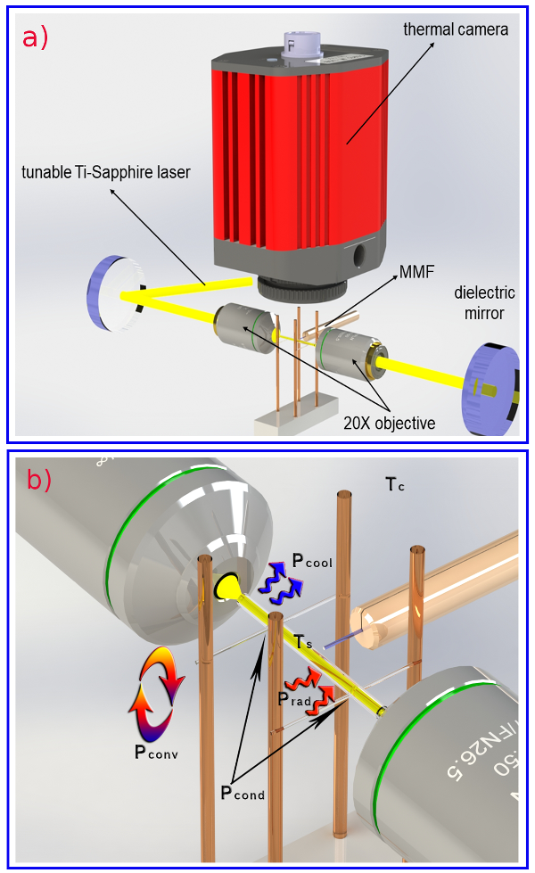
The fluorescence spectral power density of the ZBLAN fiber, , is measured from the side by a multimode optical fiber, which is coupled to a spectrometer. We note that the position of this multimode optical fiber does not change relative to the ZBALN fiber during the LITMoS test. Therefore, the absorbed power density, at each pump wavelength, , is proportional to the total collected fluorescence spectral power. In other words, , where the integral is performed over the entire fluorescence spectrum, and the subscript in signifies that the fluorescence spectral power density relates to pumping the ZBLAN fiber at . We emphasize that by changing , only the overall intensity of is re-scaled and its spectral form does not change. is proportional to the change in the temperature, , of the fiber, which is proportional to of the image captured by the thermal camera at each . Therefore, for the pump wavelength, , the cooling efficiency is approximated by .
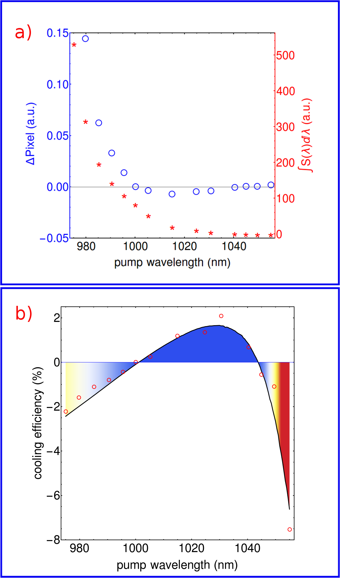
In Fig. 2a, the blue circles correspond to (change in the pixel value of the thermal camera image) and the red asterisks represent . The ratio is plotted in Fig. 2b and is fitted to Eq. 1, where the ratio is renormalized by a single overall scaling factor to conform to Eq. 1. We note that follows a strict spectral function of the form PhysRevApplied.11.014066 ; newell2007temperature ; aull1982vibronic :
| (3) |
which is used in Eq. 1 and Eq. 2 to perform the fit. Here, is the Planck constant, is the Boltzmann constant, is the speed of light in vacuum, and can be the room temperature as long as the temperature variation due to ASF cooling is not large. Equation 3 allows us to replace in Eq. 2 with , where is the absorption coefficient normalized to its peak value, . Therefore, the fitting procedure in Fig. 2b becomes a two-parameter fit (besides the overall scaling), to determine the ratio and the external quantum efficiency, . We find that and .
III Measuring the resonance absorption
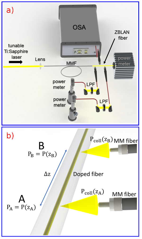
In the previous section, we managed to determine the external quantum efficiency, , along with the ratio of the parasitic background absorption to the peak resonant absorption, . In order to find the actual values of and (not just the ratio), we can now use the MACSLA method peysokhan2019method ; peysokhan2019non ; peysokhan2018non . The MACSLA method is based on comparing the collected spontaneous emission power at two arbitrary points along the fiber for different pump wavelengths. For a multimode optical fiber, due to a larger Yb-doped core diameter and consequently a stronger signal from the side of the fiber, it is not necessary to use a lock-in amplifier that was detailed in Ref. peysokhan2019method for a single-mode implementation. Here, we measured the spontaneous emission power directly by a power meter from the side of the fiber. Because the Yb-doped ZBLAN fiber is multimode, we used a passive multimode optical fiber to fully scramble the pump modes before coupling the pump to the core of the active fiber to improve the pump absorption efficiency.
The experimental setup is shown in Fig. 3(a), where a Tunable Ti:Sapphire laser beam is coupled to a multimode fiber (infinicore 300, Corning) with the length of 3 m and the output of the multimode fiber is butt-coupled to the ZBLAN fiber. Two other multimode fibers (M124L02, Thorlabs) are employed to collect the spontaneous emission from the side of the doped fiber at two different locations, points A and B marked by positions and , respectively, alongside the ZBLAN fiber. The collected side light is filtered with a 1.0 µm long-pass filter to remove the scattered pump and the filtered collected fluorescence is measured with a sensitive power meter (S120C, Thorlabs). Figure 3(b) shows a schematic of the MACSLA method.
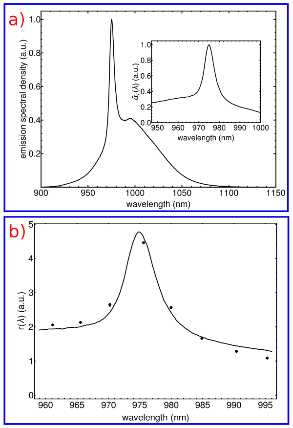
The power spectral density of the Yb-ZBLAN fiber is shown in Fig. 4(a). The inset shows the resonant absorption coefficient, which is normalized to its peak value and is calculated by using the McCumber theory mccumber1964einstein . The fitted line to the experimental measurements related to is shown in Fig. 4(b). The points indicate the values of measured at eight different wavelengths, and the fitting curve comes directly from the resonant absorption spectrum shown as the inset in Fig. 4(a). The final outcome of the fitting process is the peak value of the resonant absorption coefficient, , which can be combined with the result form the LITMoS test to give .
The results presented in sections II and III amount to a detailed laser-cooling characterization of the Yb-doped ZBLAN optical fiber using the LITMoS and MACSLA methods. In particular, we have captured the wavelength dependence of the cooling efficiency , the value of the external quantum efficiency , the peak value and wavelength dependence of the resonance absorption coefficient , as well as the value of the parasitic background absorption . The accurate determination of these parameters is essential for properly designing a radiation-balanced fiber laser or amplifier, an example of which will be done in the next section
IV Simulation and the results
In this section, we use the experimental results on the detailed characterization of the Yb-doped ZBLAN fiber from sections II and III to investigate the possibility of designing a viable radiation-balanced fiber laser. Our simulations are intended to highlight the possibility of designing such lasers with negligible heat production to address the laser heating and mode-instability problems. For our simulations, we use the main cooling-related parameters such as the cooling efficiency as a function of the wavelength, resonance absorption coefficient, background absorption coefficient, and the external quantum efficiency, all of which were found experimentally in the previous sections. The platform for our design is a double-cladding fiber laser geometry with two distributed Bragg reflectors on each side of the fiber as shown in Fig. 5, which is the common platform for high-power operation.

We consider an active fiber of length with the dopant density , which is assumed to be constant along the fiber (independent of the position ). The pump power at wavelength is coupled into the inner cladding at , propagates along the fiber, and is gradually coupled into and absorbed by the core. The unabsorbed portion of the pump that reaches the output reflector at is reflected back with 100% efficiency (=1). For all our simulations, the reflection coefficient at the signal wavelength of the input mirror at is 100%, i.e., . The reflection coefficient of the output coupler at the signal wavelength, i.e., , will be optimized for the best performance in our simulations. Note that the material and dopant properties of the fiber studied for this simulation are exactly the same as the fiber characterized in the previous sections; however, its geometry is different and customized for high-power operation as shown in Fig. 5, i.e., a single-mode core and a double-cladding geometry.
| Symbol | Parameter | Value |
| core diameter | 6.5 µm | |
| cladding diameter | 125 µm | |
| signal power filling factor | 0.89 | |
| pump power filling factor | ||
| concentration | ||
| upper manifold lifetime | 1.7 ms | |
| H | convective heat transfer coefficient | |
| absorption cross section | ||
| emission cross section | ||
| mean florescence wavelength | 994.96 nm | |
| background absorption (pump & signal) | ||
| external quantum efficiency | ||
| pump reflection of output mirror | ||
| signal reflection of input mirror |
The fraction of the pump power coupled to the active core of the fiber is represented by the power filling factor , which is assumed to be the ratio of the area of the active core to the area of the multimode inner cladding. The generated and amplified laser signal power, , is concentrated mainly in the core with the power filling factor (core overlap factor) . Our analysis is based on the commonly used rate equation model for Yb-doped fibers kelson1998strongly . We also consider the background absorption losses to be the same () for both the signal and the pump. For continuous wave (CW) lasers, the set of coupled time-independent steady-state rate equations and pump/signal propagation equations are given by:
| (4) | ||||
| (5) | ||||
| (6) |
where we have used the following definitions:
| (7) | ||||
Here, is the upper manifold population, which varies along the fiber, is the total concentration, is the signal (pump) wavelength, is the absorption cross section at the signal (pump) wavelength, is the emission cross section at signal (pump) wavelength, is the upper manifold lifetime, and is the cross-sectional area of the core. The superscripts and coefficients in the pump and signal power propagation equations signify the positive and negative propagation directions, respectively. We have used the values of the parameters reported in Table 1 in our simulations. The value of concentration in Table 1 is consistent with our measured value of .
To achieve the anti-Stokes fluorescence cooling (and consequently the RBL condition), the laser must be pumped at a wavelength longer than the mean fluorescence wavelength (). We measured the in our Yb-doped ZBLAN fiber sample to be 994.96 nm. In conventional fiber lasers, the fiber is pumped at the wavelength corresponding to the peak of the absorption, which is approximately 975 nm. For the RBL design, the pump wavelength is considerably longer at which the pump absorption coefficient is significantly reduced. Therefore, the optimum design parameters for an RBL system, specifically and , would have to be quite different from that of a conventional fiber laser. An important metric for the performance of a high-power laser is its efficiency; therefore, we compare the maximum efficiency achievable by the laser system pumped at with the signal operating at .
Figure 6 shows a density plot of the optimum efficiency as a function of the pump and signal wavelengths. The efficiency is defined as the output signal power divided by the input pump power. At every point in Fig. 6 identified by a pair, we run an optimization code to find the length and the output signal reflectivity corresponding to the maximum achievable output signal power for 80 W of input pump power. Therefore, the efficiency at each point is the maximum value that is achievable in a system design. Of course, the values of and can be widely different at different points in Fig. 6. For example, the optimum length and reflectivity for and are 24.1 m and 30%, but the same parameters for and are 8.2 m and 4%. Figure 6 provides a powerful comparison of the maximum achievable efficiencies at different wavelengths, where one need not worry about whether the lower efficiency is because of the choice of the wavelengths or because of the non-optimal choice of the fiber length and output reflectivity. This method of comparison with full optimization is absolutely necessary, because optimum RBL design parameters can be very different from those of conventional fiber lasers.
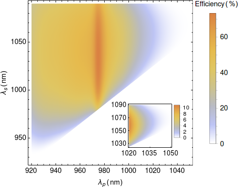
According to the results presented in Fig. 6, the maximum efficiency of around 70% is obtained for the pump wavelength of around 975 nm, which corresponds to the peak of the absorption cross section of the Yb-doped ZBLAN. In RBL systems, the pump wavelength is typically longer than 1020 nm. The inset in Fig. 6 is a magnification of the density plot over the range of wavelengths, which are most relevant for an RBL design. It can be seen that a range of 5-10% efficiency is the best that can be achieved in the Yb-doped ZBLAN fiber explored here. These general observations persist for any Yb-doped optical fiber in an RBL design: the maximum achievable efficiency is reduced as a trade-off for the better heat-management or the total heat mitigation in a strictly RBL system.
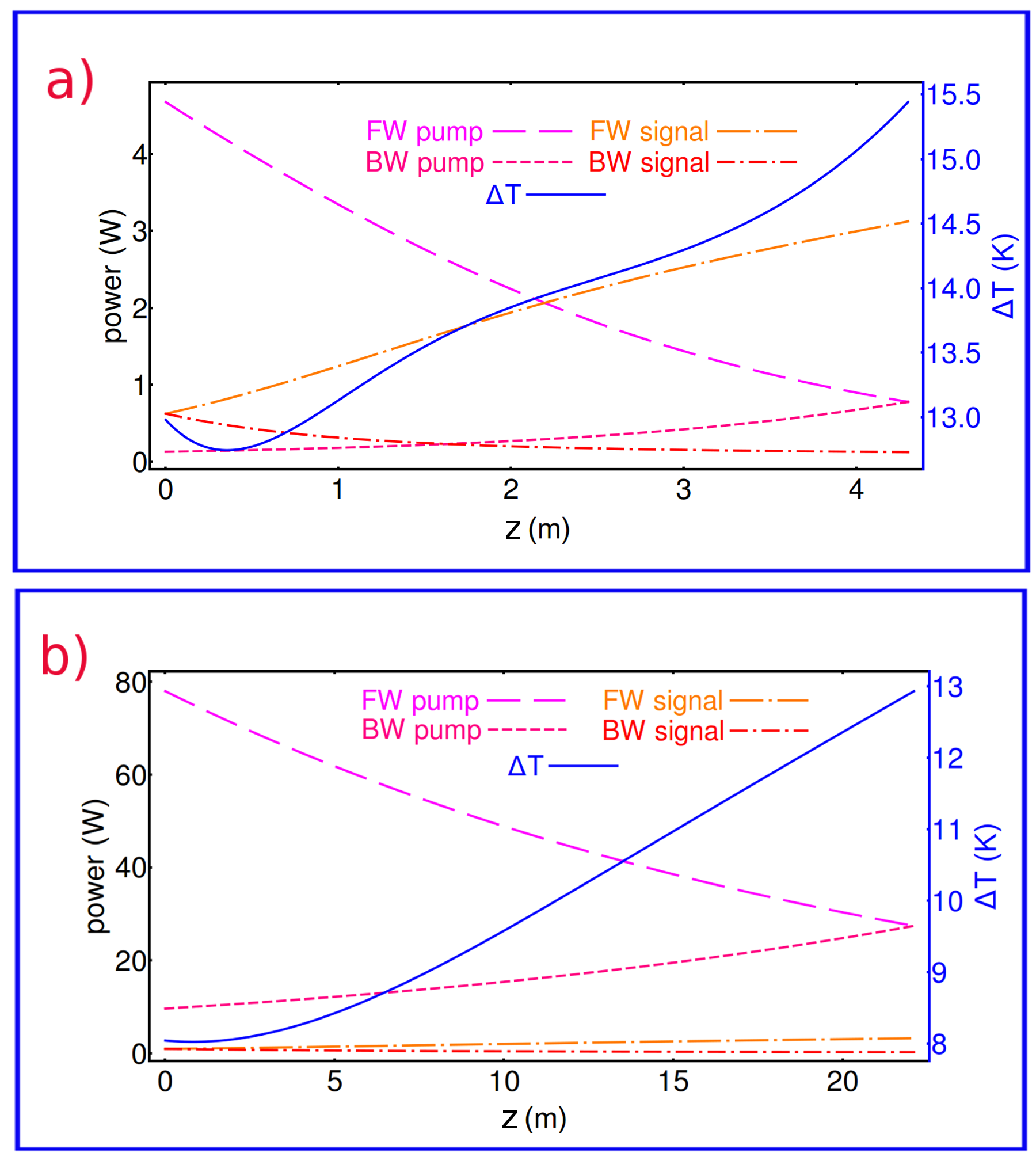
Now that we have an account of the maximum achievable efficiency from Fig. 6, we still need to answer the key question for an RBL system design: is it possible to have a fiber RBL with the same output power as a conventional fiber laser, and with the additional benefit of generating little or no heat? This is the central question in designing a meaningful fiber RBL. To explore this, we consider two simulations: first for a conventional fiber laser pumped at presented in Fig. 7a, and second an RBL fiber laser pumped at presented in Fig. 7b. The output signal in both lasers is generated to be at and is 3 W in power. Both systems are optimized for maximum efficiency. Of course, for the conventional fiber laser corresponding to Fig. 7a, the required pump power is only 4.68 W because of the higher efficiency. However, for the RBL design, we need 78 W of input pump power to achieve 3 W of output signal power due to the lower efficiency. In each plot, we show the temperature rise () as a function of along the fiber. It can be seen that the temperature rise in both designs is comparable, i.e., although the RBL design is pumped at a wavelength at which ASF cooling is mitigating some of the generated heat, its lower efficiency is resulting in the same level of temperature rise. This means that we cannot obtain any meaningful design because the best we can achieve is the same level of temperature rise albeit with a substantially higher pump power. A slightly better heating performance in the RBL design does not justify a 20-fold increase in the pumping power.
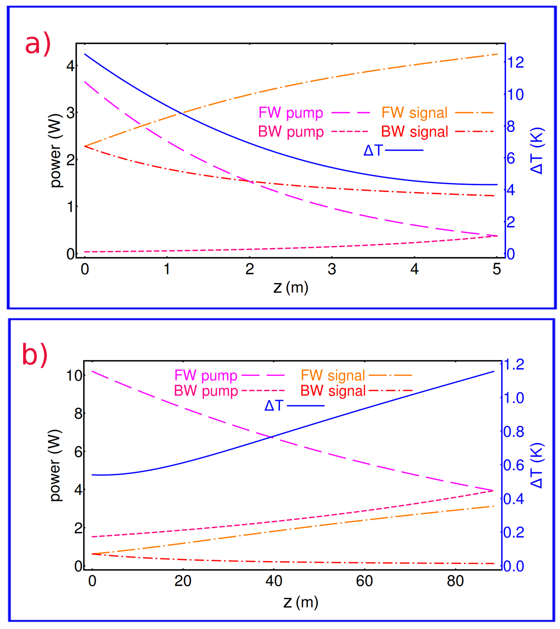
We have identified the large value of the background absorption as shown in Table 1 to be the root cause of making such RBL designs pointless as shown in Fig. 7. Therefore, the key to achieving a viable RBL system is to lower the value of the parasitic background absorption, which should be tackled by the proper fabrication and composition of the glass. To support this argument, we have repeated the simulation presented in Fig. 7 with a 10-fold reduction in the background absorption, i.e. knall2019demonstration . In fact, this a totally reasonable assumption, considering the fact that the value of that we measured earlier for the ZBLAN fiber appears to be too high, most likely due to the age of the sample and exposure to moisture and oxygen. After optimizing the cavity and finding the best reflector and length of the fiber for 3 W of output signal power, we show the designs in Fig. 8. Fig. 8a which corresponds to the conventional laser is slightly cooler than the design in Fig. 7a; however, the RBL design in Fig. 8b shows much smaller temperature rise compared with Fig. 7b, hence confirming our claim.
V Discussion and Conclusion
Anti-Stokes fluorescence cooling and radiation-balancing of fiber lasers and amplifiers rely on the availability of cooling-grade rare-earth-doped optical fibers. Herein, we have performed a detailed investigation of a Yb-doped ZBLAN optical fiber to assess its gain, loss, and cooling-related parameters. The techniques are based on the LITMoS test developed in Sheik-Bahae’s research group and the MACSLA method recently developed in our group and give accurate results on the cooling behavior of the Yb-doped ZBLAN fiber. A main advantage of the MACSLA method is that unlike the cutback method, it is not destructive. We emphasize that this work constitutes the first such detailed assessment of a cooling-grade optical fiber over a range of wavelengths. More importantly, the entire measurement is performed in atmospherics pressure using conventional table-top optical equipment. It is shown that the specific ZBLAN fiber sample measured in the experiments is cooling-grade. However, its parasitic background absorption is too large to be used for proper radiation-balancing in a fiber laser or amplifier design.
As it is shown in Fig. 6, the maximum efficiency for our Yb-doped ZBLAN fiber is obtained when it is pumped around 975 nm wavelength, while the efficiency of the laser in favorable wavelengths for RBL operation () is 7 times smaller. This lower efficiency is mainly due to the smaller absorption cross section of the pump power at RBL pump wavelengths. In order to asses the viability of an RBL design, we compared a conventional laser pumped at 975 nm wavelength with an RBL design pumped at (see Fig. 7). The output signal in both lasers was assumed to be 3 W in power at and both systems were optimized for maximum efficiency (fiber length and output signal reflectivity). We observed that the temperature rise in both designs were comparable, while the RBL design required a 20-fold larger pump power, making the RBL design totally unpractical. We attributed the problem to the relatively large value of the parasitic absorption of the pump ; in a separate simulation in Fig. 8, we showed that a 10-fold reduction in can reduce the heating in the RBL design significantly and make it viable. Therefore, we conclude that the key to achieving a viable RBL design in optical fibers is to focus on the fabrication and composition of the glass to reduce . For fiber lasers, because the parasitic heat is proportional to and the pump/signal powers, and the fact that the heat is all dumped in small core/cladding cross sections, the demand on reducing is higher than other forms of RBL lasers. In fact, our analysis has shown that while the value of is small enough to make our sample a cooling-grade fiber, it is not sufficiently small to make it a viable gain medium for RBL operation. Therefore, as far as fiber lasers are concerned, a viable RBL laser is more demanding on the parasitic absorption coefficient than the laser cooling experiment.
VI Appendix: Derivation of the Cooling Efficiency Formula
The cooling efficiency, , is defined as the net power density (per unit volume) extracted from the material () per unit power density absorbed or scattered (): . We can write , where is the fraction of the ASF power density that escapes the cooling material. The absorbed power density is given by , where is the pump intensity, is the resonant absorption of the pump laser due to the presence of the gain materials (Yb ions in here), represents the parasitic background absorption and scattering of the pump laser. The ASF power density is therefore given by , where is the mean florescence frequency, is the number density of the excited upper level in the quasi two-level Yb ions, and () is the radiative (non-radiative) decay rate of the excited state of the doped ions. is the extraction (escape) efficiency and is the fraction of photons which are radiated but are trapped inside the host. The rate equation can be expressed as
| (8) |
where we have assumed that the trapped florescence is reabsorbed by the Yb ions. In steady-state, where , we can solve for and obtain , where the external quantum efficiency is given by , and () is the pump (mean florescence) wavelength. We therefore have
| (9) |
We can use these results to present the cooling efficiency in the form of Eq. 1.
VII Methods: Cooling grade polishing of the ZBLAN fiber
The laser cooling and LITMoS test are very sensitive to surface impurities: dust particles, contamination, or scratches on the fiber facets, which act as sources of external heating and can negatively impact the laser cooling experiment. Therefore, high-quality polishing and cleaning of the optical fiber facets are critical steps for a successful LITMoS experiment seletskiy2010laser ; peysokhan2018measuring . ZBLAN fibers are made from a soft glass, which is prone to oxidation; therefore, it is much harder to polish their facets to a high-quality finish compared with silica fibers. Moreover, commercial equipment for polishing and processing ZBLAN fibers are not as widely available as for silica fibers. In this section, we detail the procedure we followed to polish our ZBLAN fiber for the laser cooling experiment.
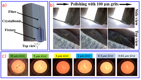
To begin the polishing process, as it is shown in Fig. 9(a), we placed the fiber on a home-made polishing fixture, which is made of stainless steel. The choice of a stainless steel polishing fixture is crucial because the aluminum oxide that forms on an aluminum fixture can easily delaminate during the polishing procedure and can scratch the fiber facet. We heated Crystalbond 509 and used it glue the fiber in its position in the polishing fixture. The fiber and Crystalbond were then polished with a 30 µm grit polishing sheet. As it is shown in Fig 9(b), this procedure continues until the full circular shape of the core-cladding of the facet of the fiber appears under the microscope. We followed a wet polishing procedure and used water-free glycol and glycerin combination for the liquid element because ZBLAN interacts with oxygen and OH. The polishing procedure continued with polishing sheets of 5, 3, 1, 0.3 and 0.02 µm grits, sequentially. After each step, the facet of fiber was inspected under a microscope and if there was a scratch, we repeated the previous steps. The final surface of the doped ZBLAN fiber is shown in the last image of Fig. 9(c).
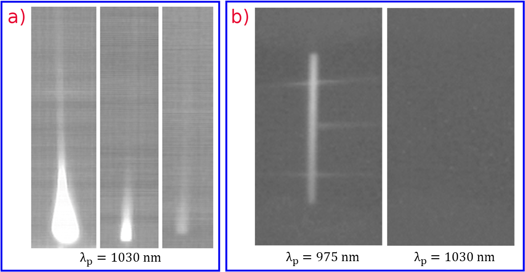
Cleaning the facets is another crucial step in fiber preparation. The cleaning is done immediately after the fiber is polished. The fiber and the polishing fixture are immersed in a 99.5% Acetone solution in an ultrasound bath for about 30 minutes for dissolving the bulk Crystalbond and detaching the fiber from the polishing fixture. The fiber is then soaked in a Citrosolve solution in the ultrasound bath to dissolve the residual Crystalbond for about one hour. The fiber is then dipped in a 99.5% Acetone solution for about 4 hours to clean the fiber thoroughly. Following this, the fiber is immersed in the 99.999% Isopropanol Alcohol for 30 minutes in the ultrasound bath to clean any trace of Aceton. To emphasize the importance of such a cooling grade polishing procedure, in Fig. 10(a) we show the thermal camera images of the ZBLAN fiber that is pumped at 1030 nm wavelength. The 3 images show, sequentially, that the improved polishing of the facets results in reduced heating of the facets. In Fig. 10(b) where the fiber is highly polished and the facets no longer are sources of parasitic heating, one can clearly observe the transition from heating when the fiber is pumped at 975 nm wavelength to cooling when pumped at 1030 nm wavelength.
Acknowledgments
The authors would like to acknowledge M. Sheik-Bahae, R. I. Epstein, M. P. Hehlen, M. Hossein-Zadeh and A. R. Albrecht for informative discussions. This material is based upon work supported by the Air Force Office of Scientific Research under award number FA9550-16-1-0362 titled Multidisciplinary Approaches to Radiation Balanced Lasers (MARBLE).
References
- (1) D. J. Richardson, J. Nilsson, and W. A. Clarkson, “High power fiber lasers: current status and future perspectives [invited],” J. Opt. Soc. Am. B 27, B63–B92 (2010).
- (2) M. N. Zervas and C. A. Codemard, “High power fiber lasers: a review,” IEEE J. Sel. Top. Quantum Electron. 20, 219–241 (2014).
- (3) D. C. Brown and H. J. Hoffman, “Thermal, stress, and thermo-optic effects in high average power double-clad silica fiber lasers,” IEEE J. Quantum Electron. 37, 207–217 (2001).
- (4) L. Zenteno, “High-power double-clad fiber lasers,” J. Light. Technol. 11, 1435–1446 (1993).
- (5) B. Ward, C. Robin, and I. Dajani, “Origin of thermal modal instabilities in large mode area fiber amplifiers,” Opt. Express 20, 11407–11422 (2012).
- (6) J. W. Dawson, M. J. Messerly, R. J. Beach, M. Y. Shverdin, E. A. Stappaerts, A. K. Sridharan, P. H. Pax, J. E. Heebner, C. W. Siders, and C. Barty, “Analysis of the scalability of diffraction-limited fiber lasers and amplifiers to high average power,” Opt. Express 16, 13240–13266 (2008).
- (7) C. Jauregui, T. Eidam, H.-J. Otto, F. Stutzki, F. Jansen, J. Limpert, and A. Tünnermann, “Physical origin of mode instabilities in high-power fiber laser systems,” Opt. Express 20, 12912–12925 (2012).
- (8) R. I. Epstein, M. I. Buchwald, B. C. Edwards, T. R. Gosnell, and C. E. Mungan, “Observation of laser-induced fluorescent cooling of a solid,” Nature 377, 500 (1995).
- (9) D. V. Seletskiy, S. D. Melgaard, S. Bigotta, A. Di Lieto, M. Tonelli, and M. Sheik-Bahae, “Laser cooling of solids to cryogenic temperatures,” Nature Photonics 4, 161 (2010).
- (10) S. R. Bowman, “Lasers without internal heat generation,” IEEE J. Quantum Electron. 35, 115–122 (1999).
- (11) S. R. Bowman, S. P. O’Connor, S. Biswal, N. J. Condon, and A. Rosenberg, “Minimizing heat generation in solid-state lasers,” IEEE J. Quantum Electron. 46, 1076–1085 (2010).
- (12) S. R. Bowman, “Low quantum defect laser performance,” Optical Engineering 56, 011104 (2016).
- (13) Z. Yang, J. Meng, A. R. Albrecht, and M. Sheik-Bahae, “Radiation-balanced Yb:YAG disk laser,” Opt. Express 27, 1392–1400 (2019).
- (14) E. Mobini, M. Peysokhan, B. Abaie, M. P. Hehlen, and A. Mafi, “Spectroscopic investigation of Yb-doped silica glass for solid-state optical refrigeration,” Phys. Rev. Applied 11, 014066 (2019).
- (15) C. Mungan, M. Buchwald, B. Edwards, R. Epstein, and T. Gosnell, “Laser cooling of a solid by 16K starting from room temperature,” Phys. Rev. Lett. 78, 1030 (1997).
- (16) T. Gosnell, “Laser cooling of a solid by 65K starting from room temperature,” Opt. Lett. 24, 1041–1043 (1999).
- (17) J. Knall, A. Arora, M. Bernier, S. Cozic, and M. J. F. Digonnet, “Demonstration of anti-stokes cooling in Yb-doped ZBLAN fibers at atmospheric pressure,” Opt. Lett. 44, 2338–2341 (2019).
- (18) E. Mobini, M. Peysokhan, B. Abaie, and A. Mafi, “Thermal modeling, heat mitigation, and radiative cooling for double-clad fiber amplifiers,” J. Opt. Soc. Am. B 35, 2484–2493 (2018).
- (19) S. Melgaard, D. Seletskiy, V. Polyak, Y. Asmerom, and M. Sheik-Bahae, “Identification of parasitic losses in Yb:YLF and prospects for optical refrigeration down to 80k,” Opt. Express 22, 7756–7764 (2014).
- (20) M. Peysokhan, E. Mobini, B. Abaie, and A. Mafi, “Method for measuring the resonant absorption coefficient of rare-earth-doped optical fibers,” Applied Optics 58, 1841–1846 (2019).
- (21) T. Newell, P. Peterson, A. Gavrielides, and M. Sharma, “Temperature effects on the emission properties of Yb-doped optical fibers,” Opt. Commun. 273, 256–259 (2007).
- (22) B. Aull and H. Jenssen, “Vibronic interactions in nd: Yag resulting in nonreciprocity of absorption and stimulated emission cross sections,” IEEE J. Quantum Electron. 18, 925–930 (1982).
- (23) M. Peysokhan, E. M. Souchelmaei, B. Abaie, and A. Mafi, “A non-destructive method for measuring the absorption coefficient of a doped optical fiber,” in Photonic Heat Engines: Science and Applications, vol. 10936 (International Society for Optics and Photonics, 2019), p. 109360K.
- (24) M. Peysokhan, E. Mobini, B. Abaie, and A. Mafi, “A non-destructive method for measuring the absorption coefficient of a Yb-doped fiber,” in Laser Science, (Optical Society of America, 2018), pp. JW3A–138.
- (25) D. McCumber, “Einstein relations connecting broadband emission and absorption spectra,” Physical Review 136, A954 (1964).
- (26) I. Kelson and A. A. Hardy, “Strongly pumped fiber lasers,” IEEE J. Quantum Electron. 34, 1570–1577 (1998).
- (27) M. Peysokhan, B. Abaie, E. Mobini, S. Rostami, and A. Mafi, “Measuring quantum efficiency and background absorption of an ytterbium-doped zblan fiber,” in CLEO: Applications and Technology, (Optical Society of America, 2018), pp. JW2A–118.