11email: {tomtsabar9@gmail.com,efifogel@gmail.com,danha@post.tau.ac.il}
Optimized Synthesis of Snapping Fixtures††thanks: This work has been supported in part by the Israel Science Foundation (grant nos. 825/15,1736/19), by the Blavatnik Computer Science Research Fund, and by grants from Yandex and from Facebook.
Abstract
Fixtures for constraining the movement of parts have been extensively investigated in robotics, since they are essential for using robots in automated manufacturing. This paper deals with the design and optimized synthesis of a special type of fixtures, which we call snapping fixtures. Given a polyhedral workpiece with vertices and of constant genus, which we need to hold, a snapping fixture is a semi-rigid polyhedron , made of a palm and several fingers, such that when and are well separated, we can push toward , slightly bending the fingers of on the way (exploiting its mild flexibility), and obtain a configuration, where is back in its original shape and and are inseparable as rigid bodies. We prove the minimal closure conditions under which such fixtures can hold parts, using Helly’s theorem. We then introduce an algorithm running in time that produces a snapping fixture, minimizing the number of fingers and optimizing additional objectives, if a snapping fixture exists. We also provide an efficient and robust implementation of a simpler version of the algorithm, which produces the fixture model to be 3D printed and runs in time. We describe two applications with different optimization criteria: Fixtures to hold add-ons for drones, where we aim to make the fixture as lightweight as possible, and small-scale fixtures to hold precious stones in jewelry, where we aim to maximize the exposure of the stones, namely minimize the obscuring of the workpiece by the fixture.
keywords:
Computational Geometry, Automation, Grasping, Fixture Design1 Introduction
A fixture is a device that holds a part in place. Constraining the movement of parts is a fundamental requirement for using robots in automated manufacturing [1],[2, Section 3.5]. There are many types and forms of fixtures; they range from modular fixtures synthesized on a lattice to fixtures generated to suit a specific part. A fixture possesses some grasp characteristics. For example, a grasp with complete restraint prevents loss of contact, prevents any motion, and thus may by considered secure. Two primary kinematic restraint properties are form closure and force closure [3]. Both properties guarantee maintenance of contact under some conditions. However, the latter typically relies on contact friction; therefore, achieving force closure typically requires fewer contacts than achieving form closure. Fixtures with complete restraint are mainly used in manufacturing processes where preventing any motion is critical. Other types of fixtures can be found anywhere, for example, in the kitchen where a hook holds a cooking pan, or in the office where a pin and a bulletin board hold a paper still. This paper deals with a specific problem in this area; here, we are given a rigid object, referred to as the workpiece, and we seek for an automated process that designs a semi-rigid object, referred to as the snapping fixture, such that, starting at a configuration where the workpiece and the holding fixture are separated, they can be pushed towards each other, applying a linear force and exploiting the mild flexibility of the fixture, into a configuration where both the workpiece and the fixture are inseparable as rigid bodies. A generated fixture has a base part, referred to as the palm, and fingers connected to the palm; see Section 2.1 for formal definitions. Without additional computational effort, a hook, a nut, or a bolt can be added to the palm resulting in a generic fixture that can be utilized in a larger system. Another advantage of the single-component flexible fixture is that it can easily be 3D-printed. We have 3D-printed several fixtures that our generator has automatically synthesized for some given workpieces. The objective of the algorithm is obtaining snapping fixtures with the minimal number of fingers. With additional care that also accounts for properties of the material used to produce the fixtures, the smallest or lightest possible fixture can be synthesized, for a given workpiece. This can (i) expedite the production of the fixture using, e.g., additive manufacturing, (ii) minimize the weight of the produced fixture, and (iii) maximize the exposed area of the boundary of the workpiece when held by the fixture.
1.1 Background
Form closure has been studied since the 19th century. Early results showed that at least four frictionless contacts are necessary for grasping an object in the plane, and seven in 3D space. Specifically, it has been shown that four and seven contacts are necessary and sufficient for the form-closure grasp of any polyhedron in the 2D and 3D case, respectively [4, 5].
Automatic generation of various types of fixtures, and in particular, the synthesis of form-closure grasps, are the subjects of a diverse body of research. Brost and Goldberg [6] proposed a complete algorithm for synthesizing modular fixtures of polygonal workpieces by locating three pegs (locators), and one clamp on a lattice. Their algorithm is complete in the sense that it examines all possible fixtures for an input polygon. Their results were obtained by generating all configurations of three locators coincident to three edges, for each triplet of edges in the input polygon. For each such configuration, the algorithm checks whether form closure can be obtained by adding a single clamp. Our work uses a similar strategy to obtain all possible configurations. In subsequent work Zhuang, Goldberg, and Wong [7] showed that there exists a non-trivial class of polygonal workpieces that cannot be held in form closure by any fixture of this type (namely, a fixture that uses three locators and a clamp). They also considered fixtures that use four clamps, and introduced two classes of polygonal workpieces that are guaranteed to be held in form closure by some fixture of this type. Wallack and Canny [8] proposed another type of fixture called the vise fixture and an algorithm for automatically designing such fixtures. The vise fixture includes two lattice plates mounted on the jaws of a vise and pegs mounted on the plates. Then, the workpiece is placed on the plates, and form closure is achieved by activating the vise and closing the pins from both sides on the workpiece. The main advantage in this type of fixture is its simplicity of usage. Brost and Peters [9] extended the approach exploited in [6] to three dimensions. They provided an algorithm that generates suitable fixtures for three-dimensional workpieces. Wagner, Zhuang, and Goldberg [10] proposed a three-dimensional seven-contact fixture device and an algorithm for planning form-closure fixtures of a polyhedral workpiece with pre-specified pose. A summary of the studies in the field of flexible fixture design and automation conducted in the last century can be found in [11]. Related studies in the field of grasping and manipulation are summarized in [12]. Subsequent works studied other types of fixtures and provided algorithms for computing them, for example, unilateral fixtures [13], which are used to fix sheet-metal workpieces with holes. Other studies focused on grasping synthesis algorithms with autonomous robotic fingers, where a single robotic hand gets manipulated by motors and being used to grasp different workpieces; an overview of such algorithms can be found in [14]. A common dilemma for all the grasping and fixture design algorithms is defining and finding the optimal grasp. Several works, e.g., [15] and [16], discuss such quality functions and their optimization.
1.2 Our Results
We introduce certain properties of minimal snapping fixtures of given workpieces. Formally, we are given a closed polyhedron of complexity and of a constant genus that represents a workpiece. The surface of a polyhedron of genus zero is homeomorphic to a sphere. In our work we allow more complicated polyhedra; see, for example, Figure 4a.111The genus counts the number of “handles” in the polyhedron; see, e.g., https://mathworld.wolfram.com/Genus.html. In our analysis in the sequel we assume that the genus is bounded by a constant. We introduce an algorithm that determines whether a closed polyhedron that represents a fixture exists, and if so, it constructs it in time. This significantly improves our simpler algorithm listed in Appendix B. We also provide an efficient and robust implementation of the latter. In addition, we present two practical cases that utilize our implemented algorithm: One is the generation of a snapping fixture that mounts a device to an unmanned aerial vehicle (UAV), such as a drone. The other is the generation of a snapping fixture that mounts a precious stone to a jewel, such as a ring. The common objective in both cases is, naturally, the firm holding of the workpiece. In the first case, we are interested in a fixture with minimal weight. In the second case we are interested in a fixture that minimally obscures the precious stone. We are not aware of similar work on semi-rigid one-part fixtures; thus, we do not conduct any comparisons, but we provide some benchmark numbers we have obtained while executing our generator. Note that, in theory, the generated fixtures prevent any linear motion, but do not necessarily prevent angular motion; however, fixtures that do not posses the form closure property are rarely obtained in practice. Handling angular motion is left for future research; see Appendix D.1.
1.3 Outline
The rest of this paper is organized as follows. Terms and definitions for our snapping fixtures and theoretical bounds and properties are provided in Section 2. The synthesis algorithm is described in Section 3 along with the analysis of its complexity. Two applications are presented in Section 4. Finally, we report on experimental results in Section 5. Appendix A provides a notation glossary. Appendix C contains proofs of several lemmas, corollaries, observations, and a theorem. We point out some limitations of our generator and suggest future research in Appendix D. An assortment of interesting workpieces and fixtures that we have 3D-printed and experimented with are shown in Appendix E.
2 Terminology and Properties
In this section we describe the structure and properties of our snapping fixtures.
2.1 Fixture Structure
![[Uncaptioned image]](/html/1909.05953/assets/figs/trunc_pyramid4.png)
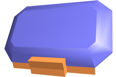
Consider an input polyhedron that represents a workpiece, such as the one transparently rendered in blue in the figure to the right. The structure of a fixture of , rendered in orange in the figure, resembles the structure of a hand; it is the union of a single polyhedral part referred to as the palm, several polyhedral parts, referred to as fingers, which are extensions of the palm, and semi-rigid joints that connect the palm and the fingers. Each finger consists of two polyhedral parts, namely, body and fingertip, and the semi-rigid joint between the body and the fingertip. The various parts, i.e., palm, bodies, and fingertips, are disjoint in their interiors. In the following we describe these parts in detail.
Definition 2.1 (-extrusion of a polygon and base polygon of an -extrusion).
Let denote a polygon in space, let denote a normal to the plane containing , and let denote the normal scaled to length . The -extrusion of is a polyhedron in space, which is the extrusion of along . The polygon is referred to as the base polygon of ; see the figure below.
We use the abbreviation -extrusion of a facet of some polyhedron to refer to the -extrusion of the geometric embedding of the facet , and we refer to the facet of that overlaps with as the base facet of the -extrusion .
Our formal computational model is oblivious to the thickness of the various parts. In this model the parts are flat and if two parts are connected by a joint, they share an edge, which is the axis of the joint. Our generator, though, synthesizes solid models of fixtures. We use -extrusion to inflate the various parts.
Let denote a snapping fixture made of a palm, fingers , and corresponding joints. The palm is an -extrusion of a facet of the workpiece . (The various values are discussed below.) Consider a specific finger of . The body of is defined by one of the neighboring facets of , denoted . The fingertip of is defined by one of the neighboring facets of , denoted , . Let denote the common edge of and , and let denote the common edge of and . Note that in some degenerate cases and are incident to a common vertex. The body of a finger is an -extrusion of . Let denote the cross product of the vector that corresponds to and the normal to the plane containing of length . Let denote the quadrilateral defined by the two vertices incident to and their translations by . The fingertip is an -extrusion of . The axis of the joint that connects the palm and the body of coincides with and the axis of the joint that connects the body of with its fingertip coincides with . The value and the values and for each finger determine the trade-off between the strength and flexibility of the joints.222Typically, these values are identical. They depend on the material and shape of the fixture. In our implementation they can be determined by the user.333For example, in several of the fixtures that we produced, they were set to 5mm.
For a complete view of a workpiece and a snapping fixture consider Figure 1. Observe that both the palm and the fingers of the fixture in the figure differ from the formal definitions above. The differences stem from practical considerations. In particular, the parts in the figure have smaller volumes, which (i) reduces fabrication costs, and (ii) resolves collision between distinct fingers. In some degenerate cases (see Figure 1d) distinct fingers could have overlapped. In the figure, the base facet of the fingertip of one finger, , coincides with , a facet of the workpiece. Likewise, the base facet of the body of the other finger, , also coincides with . Avoiding overlaps is achieved by simultaneously shrinking the base facets and . Now, the fingertip grips only the tip of and the body is stretching only on a small portion of the workpiece facet. As another example, consider the body of a finger depicted in Figure 1LABEL:sub@fig:fix1:t; it is the -extrusion of a quadrilateral defined by two points that lie in the interior of and two points that lie in the interior of , as opposed to the formal definition above, where the body is the -extrusion of the entire facet of . Also, in reality, parts are not fabricated separately, and the entire fixture is made of the same flexible material. Instead of rotating about the joint axes, the entire fingers bend. The differences, though, have no effect on the correctness of the proofs and algorithm (which adhere to the formal definitions) presented in the sequel. These structural changes and the extrusion values, merely determine the degree of flexibility and strength of the fixture; see Appendix D.3 and Appendix D.4.
2.2 The Configuration Space
The workpiece and its snapping fixture form an assembly. Each joint in the fixture connects two parts; it enables the rotation of one part with respect to the other about an axis. Each joint adds one degree of freedom (DOF) to the configuration space of the assembly.
In our context, the workpiece and its snapping fixture are considered assembled, if they are infinitesimally inseparable. When two polyhedra are infinitesimally inseparable, any linear motion applied to one of the polyhedra causes a collision between the polyhedra interiors. The workpiece and the fixture are in the serving configuration if (i) they are separated (that is, they are arbitrarily far away from each other), and (ii) there exists a vector , such that when the fixture is translated by , as a result of some force applied in the direction of , exploiting the flexibility of the joints of the fixture, the workpiece and the fixture become assembled. When the workpiece and its snapping fixture are separated, the fixture can be transformed without colliding with the workpiece to reach the serving configuration.444The video clip available at http://acg.cs.tau.ac.il/projects/ossf/snapping˙fixtures.mp4 illustrates the snapping operation.
2.3 Spreading Degree
![[Uncaptioned image]](/html/1909.05953/assets/x1.png)
The spreading degree is the number of facets involved in the definition of a finger. In this paper we restrict ourselves to snapping fixtures that have fingers with spreading degree two, which means that the body of every finger is based on a single facet of . Every finger (the body and the fingertip) stretches over two facets of . Naturally, fingers with a higher spreading-degree reach further. An icosahedron, for example, (depicted in the figure above) does not admit a valid fixture with spreading degree two. This is proven by exhaustion running our implemented algorithm.
2.4 Fixture Planning
The basic objective of our fixture algorithms is obtaining fixtures with the minimal number of fingers. Our generator is of the exhaustive type. As explained in Section 3, it examines many different possible candidates of fingers, before it reaches a conclusion. The simple (and implemented) algorithm, for example, visits every valid fixture (of 2, 3, or 4) fingers; thus, it can be used to produce all or some valid fixtures according to any combination of optimization criteria. As aforementioned, the generator synthesizes fixtures of spreading degree two. Extending the generator to enable the synthesis of fixtures with an increased spreading degree (without further modifications) will directly increase the search space exponentially.
2.5 Properties
Definition 2.2 (unit circle, semicircle, open semicircle).
An open semicircle is a semicircle excluding its two endpoints. An open hemisphere is a hemisphere excluding the great circle that comprises its boundary curve.
Definition 2.3 (Covering set).
Let be a finite set of subsets of and be a set of points in . If then is a covering set of .
A pair of open unit semicircles (respectively, hemispheres) are called antipodal if the closure of their union is the entire unit circle (respectively, sphere).
For lack of space, we defer portions of the formal analysis to the appendix. In particular a sequence of lemmas proved in the appendix yield the following corollaries. The proofs of the corollaries, observations and theorem in the remainder of this section, appear in Appendix C.
Corollary 2.4.
Let be a set of four open unit semicircles that cover the unit circle . is minimal (i.e., for every open semicircle , is not a covering set of ) iff it consists of two antipodal pairs of open unit semicircles.
Corollary 2.5.
Let be a set of distinct open unit semicircles that covers ; if , then there exists , and covers .
Corollary 2.6.
Let be a set of six open unit hemispheres that cover the unit sphere . is minimal iff it consist of three antipodal pairs of open unit hemispheres.
Corollary 2.7.
Let be a set of distinct open unit hemispheres that covers ; if , then there exists , and covers .
When a facet of the workpiece partially coincides with a facet of the fixture, the workpiece cannot translate in any direction that forms an acute angle with the (outer) normal to the plane containing (without colliding with the fixture). This set of blocking directions comprises an open unit hemisphere denoted as . Similarly, denotes the mapping from a set of facets to the set of corresponding open unit hemispheres; see, e.g., [17]. Let denote the set of facets of the workpiece that are coincident with facets of the fixture in some fixed configuration. If the union of all blocking directions covers the unit sphere in that configuration, formally stated , then the workpiece cannot translate at all.
Let denote the set of all facets of the fixture . Let denote the singleton that consists of the base facet of the palm of , and let and , , denote the base facet of the body and the base facet of the fingertip, respectively, of the -th finger of , where indicates the number of fingers. Let and denote the set of the base facets of the body parts of the fingers of and the set of the base facets of the fingertip parts of the fingers of , respectively. Let denote the set of all base facets of the parts of , that is . Let denote the set of all base facets of the parts of excluding the base facets of the fingertips, that is, .
If the fixture resists any linear force applied on the workpiece while in the assembled state and there exists a collision free path (in the configuration space) between any separated configuration and the assembled configuration then our fixture is valid. We relax the second condition for practical reasons; instead of requiring a full path, we require a path of infinitesimal length. Formally we get:
-
\phantomsection
Condition 1
:
.
-
\phantomsection
Condition 3
:
.
If the second condition holds, a serving state exists (assuming the flexibility of the joints cancels out the obstruction induced by the presence of the fingertips).
A candidate finger of an input polyhedron is a valid finger of at least one possible fixture of .
Observation 1
The number of candidate fingers of an input polyhedron is linear in the number of vertices of .
Theorem 2.8.
Every valid snapping fixture can be converted to a four-finger snapping fixture. Sometimes four fingers are necessary.
Observation 2
A single-finger fixture does not exist.


3 Algorithm
A snapping fixture (of spreading degree two) is formally defined by a pair that consists of (i) an index of a facet of , and (ii) a set of pairs of indices of facets of . The palm of is the -extrusion of the facet . Each member pair of indices define a finger of . The body and fingertip of the finger are the - and -extrusion values of the facets and , respectively.
A simple algorithm that exhaustively searches through all valid snapping fixtures with 2, 3, or 4, fingers, of a given polyhedron and runs in time is listed in Appendix B. Here, we introduce a much more parsimonious algorithm that uses a different method to generate 4-finger fixtures, yielding an algorithm that generates one fixture if exists with the minimal number of fingers and runs in time.
Procedure 1
(minimalSnappingFixture) The procedure accepts a polyhedron as input and returns a fixture of if exists with the minimal number of fingers; see Algorithm 1. The algorithm consists of two phases. In the first phase we compute a data structure that associates palms and candidate fingers that extend from them. The second phase consists of three subphases in which we extract subsets of fingers of size, 2, 3, and 4, respectively, for each palm stored in and examine whether the palm and the subset of fingers form a valid fixture. Once we strike one, we return it.
Procedure 2
(neighbors) The procedure accepts a facet of a polyhedron and returns all the neighboring facets of .
Procedure 3
(subsets) The procedure accepts a set and a positive integer ; it returns all subsets of of cardinality .
Procedure 4
(validFixture) The procedure accepts a snapping fixture and determines whether it is a valid snapping fixture based on Items \phantomsection Condition 1 : and \phantomsection Condition 3 : defined in Section 2.5.
In each one of the subphases of the second phase we iterate over all facets of and treat each facet as a potential base facet of the palm of a valid fixture (unless a fixture was found in a previous subphase). In the following, we narrow down the search space for fixtures with four fingers, once it has been established that our workpiece does not have a fixture with two or three fingers. Consider a polyhedron that does have a valid fixture, say (with an arbitrary number of fingers). There exists a subset , such that (i) is a covering set of the closed hemisphere , and (ii) . (This follows the same reasoning as in the proof of Theorem 2.8, which appears in Appendix C.) The composition of can be categorized into four cases listed below. We show that only one of theses cases, namely Case IV, must be considered when searching for a fixture with four fingers.


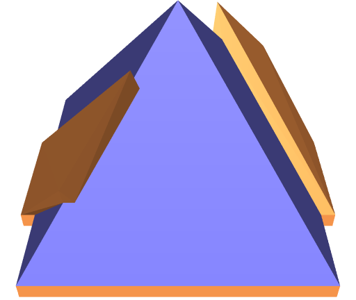
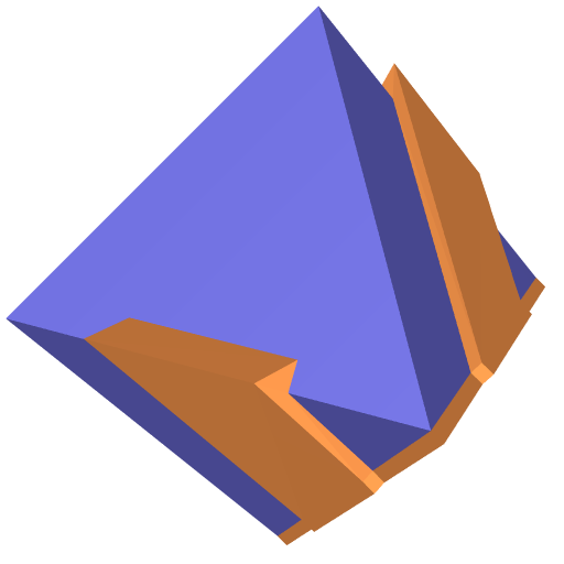
Case I: . The tetrahedron and the fixture depicted in Figure 3a demonstrate this case. At most three distinct fingers of are needed; it implies that finding a fixture similar to , but only with these three fingers, during the first or second subphases is guaranteed.
Case II: . The tetrahedron and the fixture depicted in Figure 3b demonstrate this case. By Corollary 2.6, consists of three antipodal pairs of open unit hemispheres. As is a covering set of and , by Corollary 2.7, . It implies that the facets in can be divided into three pairs of non-empty sets, such that each set is a collection of all facets with the same normal, and the two sets of every pair correspond to opposite normals, respectively. Without loss of generality, we assume that does not have coplanar facets that are neighbors, because such facets can be merged. Next, observe that the facets in must be parallelograms. Assume, for contradiction, that there exists a facet that is not a parallelogram. It implies that has at least three neighboring facets that are pairwise non-parallel, which implies that, together with , contains at least four open hemispheres that are pairwise non-antipodal, a contradiction.
must have at least one finger, say , such that the normal to the base facet of its fingertip, say , is opposite to the normal of the base facet of the palm . Let denote the base facet of the body of . Consider the set . Observe that . Let be the antipodal counterpart of . Consider the finger , such that is either the base facet, , of the body of or the base facet, , of the fingertip of . Naturally, is a member of . (i) If , then, since is a neighbor of and , must be a member of as well. Now, consider the set , and observe that . (ii) If , then let be one of the neighbors of that is not parallel to . Recall, that the facet has four neighbors—two pairs of parallel facets. As and are parallel, must be a member of as well. If , replace the fingertip of with a fingertip, the base of which is . Now, consider the set , and observe that . It follows that there exists a third finger, say , such that either or , where and are the base facets of the body and fingertip, respectively, of , which obviates the need for further fingers. It implies that finding a valid fixture during the first or second subphases is guaranteed.
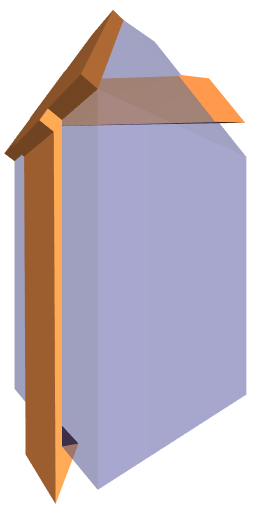
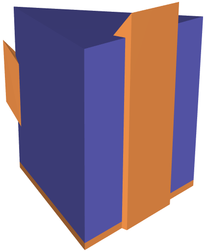
Case III: and there exists a facet , such that and are antipodal. The triangular prism and the fixture depicted in Figure 3c demonstrate this case. As in the previous case, must have at least one finger, say , such that the normal to the base facet of its fingertip, say , is opposite to the normal of the base facet of the palm . Let denote the base facet of the body of . Consider the set . Since , at most two additional distinct fingers of are needed; it implies that finding a fixture similar to , but only with three fingers, during the first or second subphases is guaranteed.
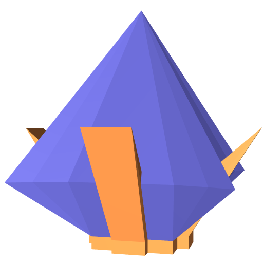
Case IV: and does not contain an open hemisphere, such that this hemisphere and are antipodal. The square pyramid and the fixture depicted in Figure 3d demonstrate this case. Observe that the fixture in the figure has two fingers. However, sometimes four fingers are necessary as established by Theorem 2.8; see, e.g., Figure 2a. This is the only case we need to consider when searching for a fixture with four fingers. Notice, that in this case, the intersections of at least two open hemispheres in with the great circle are pairwise antipodal open unit semicircles.
Procedure 5
(fourFingersFixtures) The procedure accepts a facet of a potential palm and a set of pairs of facets, where each pair defines the base facets of the body and fingertip of a candidate finger, as input. It returns a valid fixture of with four fingers, if there exists one, such that is the base facet of its palm, and its configuration matches Case IV above. Let denote the set of unique facets in . Let denote the closed hemisphere that must be covered by the open hemispheres . The procedure first divides all the hemispheres in into equivalence classes, such that the intersections of all hemispheres in a class with the unit circle is a unique open semicircle. Let denote the unique open semicircle associated with the equivalence class . There is a canonical total order of hemispheres within each class: Let and be two hemispheres in some class; then iff . Then, the procedure identifies pairs of equivalence classes , such that and are antipodal open semicircles. For each pair, the procedure traverses all other equivalence classes twice searching for two additional equivalence classes and , such that the set covers . If it finds such four equivalence classes, it implies that there exists a valid fixture with four fingers , such that the maximal hemisphere associated with is either or . In this case the procedure returns such a fixture.
The complexity of the algorithm is the accumulated complexities of Phase 1 and Subphases 2.1, 2.2, and 2.3. The efficiency (low running-time complexity) of Subphase 2.2 stems from an observation on the maximum number of possible candidates for this subphase, which in turn relies on the genus of the polyhedron, as we discuss next.
Lemma 3.1 (Genus of complete bipartite graphs [18]).
The genus of the complete bipartite graph, , with nodes in one side and in the other, is .
Lemma 3.2.
Given an input polyhedron of genus . Let be a triplet of candidate fingers. Let be the set of plams, such that all fingers in extend every palm in . Then, .
Proof 3.3.
Let be the set of three facets of that correspond to the three base facets of the bodies of the fingers in . Let be the set of facets of that correspond to the base facets of the palms in . Let denote the vertices, edges, and facets of , respectively. Let be the dual graph of , where each facet is represented as a node, and two nodes are connected by an arc if the corresponding two facets are neighbors. According to Euler characteristic, the genus of is given by , which is equal to . Consider the subgraph of that consists of the nodes that correspond to the facets in and in . The genus of is at most . Since each facet in and each facet in are neighbors, is a complete bipartite graph . By Lemma 3.1, the genus of is . Hence, . ∎
Theorem 3.4.
Algorithm 1 runs in time, where is the number of vertices of the input polyhedron.
Proof 3.5.
During the first phase we list all the potential palms, each palm together with all the fingers that can be connected to it. The overall number of potential fingers is twice the number of edges in the polytope; see Observation 1. Since The number of facets and the number of edges in a polytope with vertices is linear in , the number of palm-finger combinations created in Phase 1 is . The second phase dominates the time complexity. We examine each subphase separately. Recall, that a potential fixture passed to validFixture (encoded by , where denotes a facet and denotes a set, the cardinality of which is fixed, i.e., 2, 3, or 4) has a fixed number of fingers. Therefore, every execution of the function consumes constant time. In the first subphase for every possible palm the function validFixture is invoked once per every subset of candidate fingers of size 2. As the number of candidate fingers is linear in , the number of pairs of fingers is in . Thus, the total complexity of this subphase is . In the second subphase for every possible palm the function validFixture is invoked once per every subset of candidate fingers of size 3. By Lemma 3.2 and the assumption that the genus of the input polyhedron is constant, while iterating over all possible fixtures that have exactly three fingers, each triplet of fingers is considered a constant number of times. Therefore, the total time consumed processing potential fixtures of three fingers is bounded by . fourFingersFixtures() is invoked once for every facet in the input polyhedron. Building the equivalence classes and finding the maximum of each class takes time. Matching maximal hemispheres of equivalence classes to form pairs of associated antipodal semicircles takes time. Finally, examining every pair, traversing all other equivalence classes for each pair, also takes time. Thus, the total complexity of this subphase is . The overall time complexity is thus .∎
4 Two Applications
We present two applications that utilize our algorithm and its implementation.
4.1 Minimal Weight Fixtures
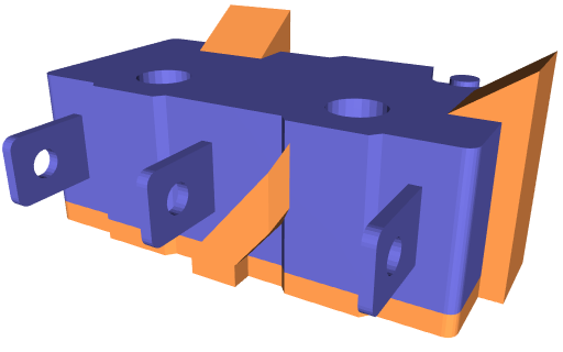
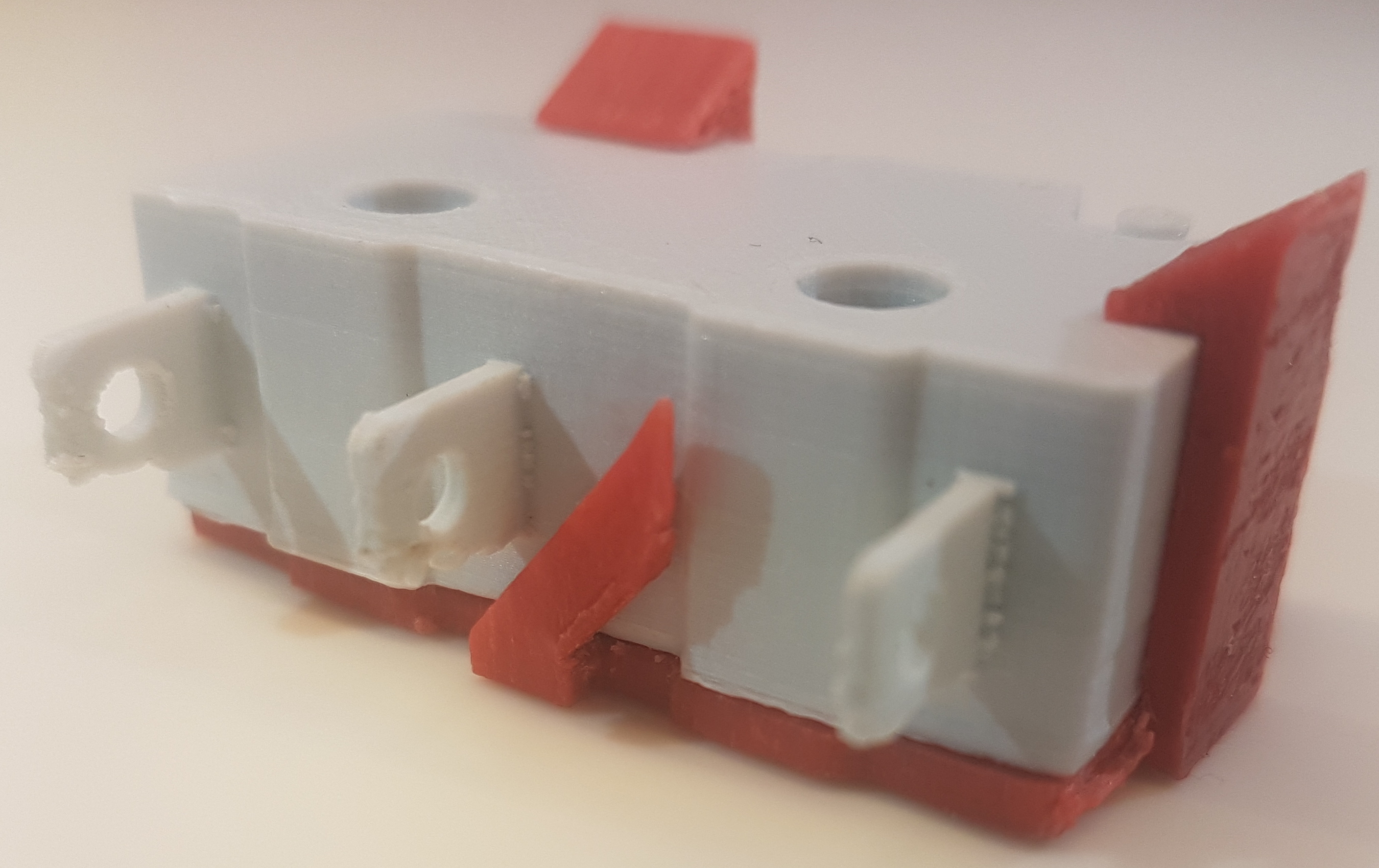
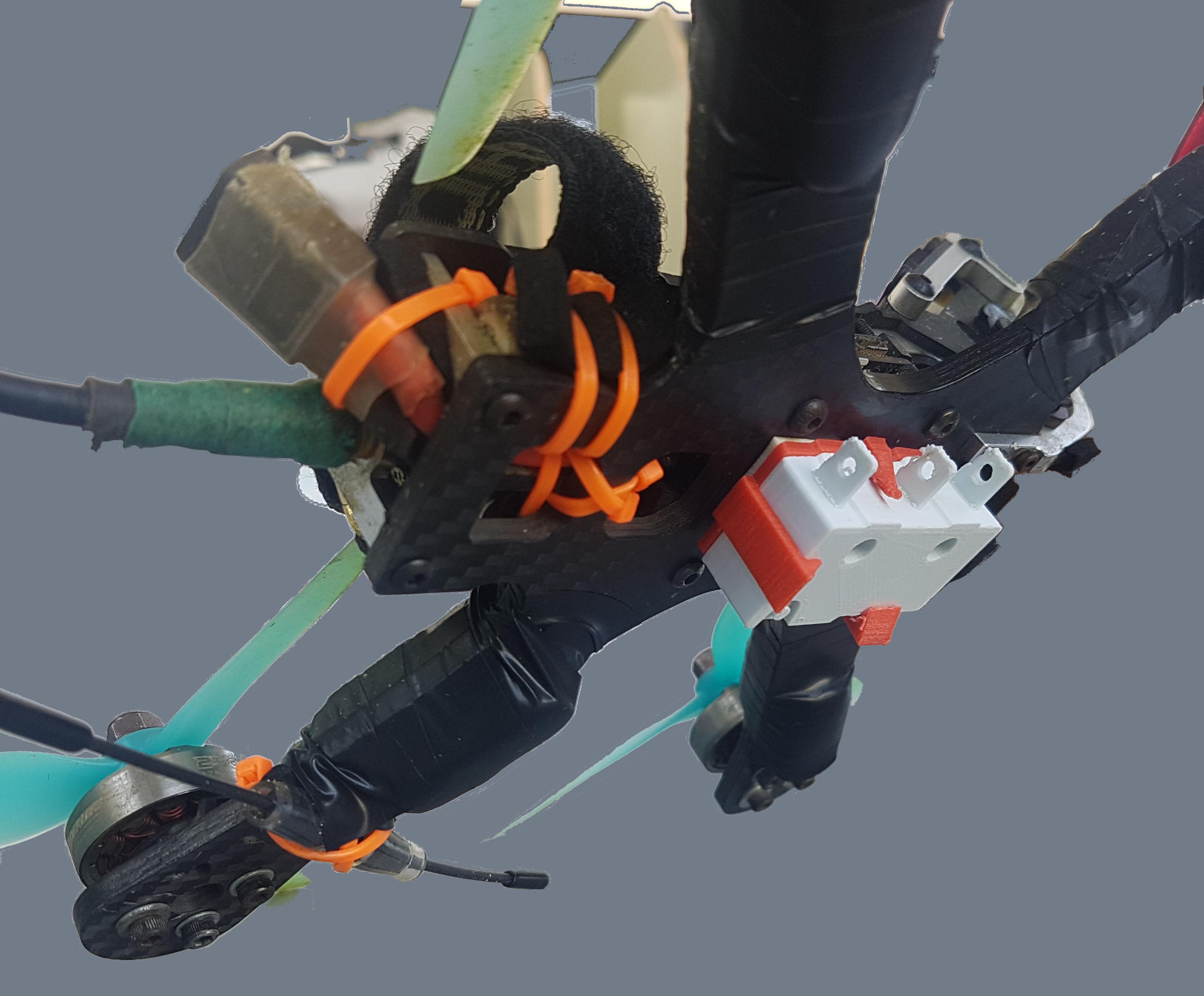
Generating lightweight fixtures that could be mounted on a UAV has been a major challenge ever since the first UAV was introduced. The desire for robust and efficient solutions to this problem rapidly scaled up during the last decade with the introduction of small drones, the weight of devices that can be mounted on which, is limited. Naturally, the device must be securely attached to the drone; however, at the same time, the holding mechanism should weigh as little as possible. Figure 4 shows a fixture generated for a micro-switch sensor, a common sensor in the field of robotics and automation. Figure 4c shows the fabricated fixture (3D printed) permanently attached to a drone. It holds a micro-switch. While the micros-switch is firmly held during flight, it can be easily replaced.
4.2 Minimal Obscuring Fixtures
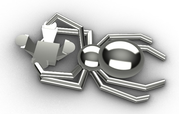
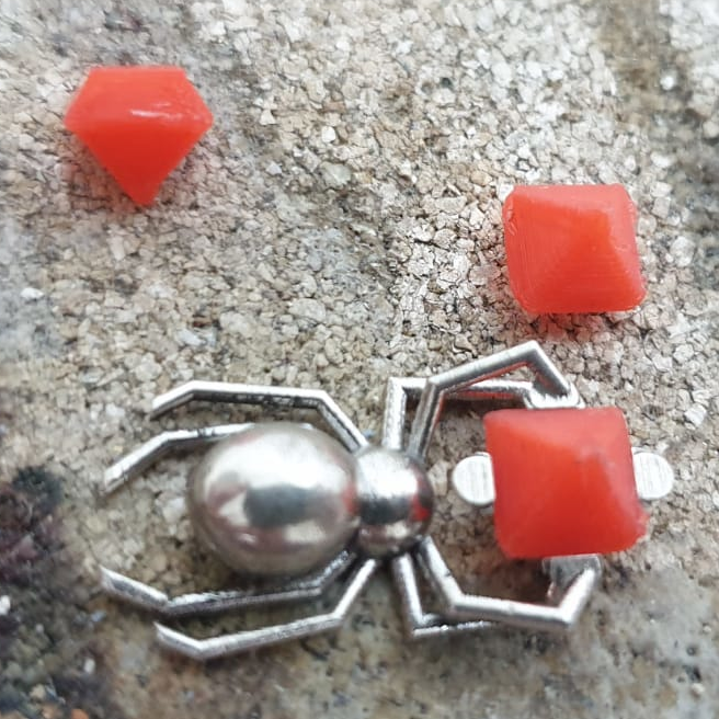
One of the objectives of jewelry making is to expose the gems mounted on a jewel, such as a ring, and reveal their allure. As with the minimal-weight fixture, the mounted gem must be securely attached to the jewel; however, the weight of the holding mechanism can be compromised. Here we seek to find a fixture that obscures the gem as little as possible, so that the gem surface is exposed as much as possible. Figure 5b shows a pendant with an integrated fixture synthesized by our generator. The fixture in Figure 5a is generated for an emerald cut; it reveals a surprising portion of the front facet of the stone.
4.3 3D Printing Considerations
We used various materials for generating snapping fixtures, such as, ABS, PLA, PETG, Nylon 12, and Sterling silver.5553D printed wax and lost-wax where used to generate fixtures made of Sterling Silver. All generated fixtures properly snapped and firmly held the workpieces. However, low quality prints (made of ABS, PLA, or PETG) occasionally broke after repeated or incautious uses. We noticed that increasing the infill density and orienting the prints such that the joint axes and the printing plate are not parallel increase the fixture durability. Also, we compensated for the limited precision of printers by scaling up the fixture to create a gap of up to 0.2mm between the fixture and the workpiece.
5 Experimental Results
The generator was developed in C++; it depends on the Polygon Mesh Processing package of Cgal [19]. Table 1 lists some of the workpieces we fed as input, and provides information about the generation of the corresponding snapping fixtures. The coordinates of the vertices of the input models were given in floating point numbers. The generator was executed on an Intel Core i7-2720QM CPU clocked at 2.2 GHz with 16 GB of RAM.
| Workpiece | Fixture | # Fixts | ||||||
| Name | # | # | # Facets | Genus | # Min | Time | Min | |
| Verts | Edges | Tris | Merged | Fingers | (ms) | Fingers | ||
| tetrahedron | 4 | 6 | 4 | 4 | 0 | 2 | 3 | 36 |
| dodecahedron666Limited precision coordinates render the actual models non-regular. | 20 | 30 | 36 | 12 | 0 | 2 | 15 | 50 |
| emerald | 34 | 96 | 64 | 25 | 0 | 2 | 39 | 8 |
| square pyramid | 5 | 8 | 6 | 5 | 0 | 2 | 4 | 24 |
| micro switch | 594 | 1,806 | 1,204 | 305 | 2 | 2 | 42,761 | 263,895 |
| cube | 8 | 18 | 12 | 6 | 0 | 3 | 20 | 216 |
| octahedron | 6 | 12 | 8 | 8 | 0 | 3 | 3 | 16 |
| torus | 32 | 64 | 32 | 10 | 1 | 3 | 307 | 2,760 |
| 4-finger | 26 | 64 | 42 | 41 | 0 | 4 | 45 | 17 |
| truncated cuboctahedron††footnotemark: | 48 | 72 | 92 | 26 | 0 | 2 | 163 | 29 |
| icosahedron | 12 | 30 | 20 | 20 | 0 | 22 | 0 | |
| 8-base cylinder | 16 | 42 | 28 | 10 | 0 | 2 | 44 | 106 |
| 28-base cylinder | 56 | 162 | 108 | 30 | 0 | 2 | 984 | 4,396 |
| 48-base cylinder | 96 | 282 | 188 | 50 | 0 | 2 | 4,672 | 24,456 |
| 68-base cylinder | 136 | 402 | 268 | 70 | 0 | 2 | 13,008 | 71,892 |
| 88-base cylinder | 176 | 522 | 348 | 90 | 0 | 2 | 27,233 | 159,124 |
| 108-base cylinder | 216 | 642 | 428 | 110 | 0 | 2 | 50,122 | 297,956 |
Acknowledgement
The authors thank Shahar Shamai for his technical support, Omer Kafri and Raz Parnafes for fruitful discussions, and Shahar Deskalo for exploiting our work while crafting a jewel.
References
- [1] H. H. Asada. Manufacturing robotics: Basic issues and challenges. IFAC Proceedings Volumes, 29(1):319–330, 1996.
- [2] M. Wilson. Implementation of Robot Systems. Elsevier, 1st edition, 2015.
- [3] D. Prattichizzo and J. C. Trinkle. Grasping. In B. Siciliano and O. Khatib, editors, Handb. of Robotics, chapter 38, pages 671–700. Springer, 2nd edition, 2016.
- [4] X. Markenscoff, L. Ni, and C. H. Papadimitriou. The geometry of grasping. Int. J. of Robotics Research, 9:61–74, 1990.
- [5] B. Mishra, J. T. Schwartz, and M. Sharir. On the existence and synthesis of multifinger positive grips. Algorithmica, 2:541–558, 1987.
- [6] R. C. Brost and K. Y. Goldberg. A complete algorithm for synthesizing modular fixtures for polygonal parts. In Proc. 1994 IEEE Int. Conf. on Robotics & Autom., volume 1, pages 535–542, 1994.
- [7] Y. Zhuang and K. Goldberg. On the existence of solutions in modular fixturing. Int. J. of Robotics Research, 15(6):646–656, 1996.
- [8] A. S. Wallack and J. F. Canny. Planning for modular and hybrid fixtures. Algorithmica, 19(1):40–60, 1997.
- [9] R. C. Brost and R. R. Peters. Automatic design of 3D fixtures and assembly pallets. Int. J. of Robotics Research, 17(12):1243–1281, 1998.
- [10] R. Wagner, Y. Zhuang, , and K. Goldberg. Fixturing faceted parts with seven modular struts. In IEEE Int. Symp. on Assembly and Task Planning, pages 133–139. IEEE Comput. Society Press, 1995.
- [11] Z. M. Bi and W. J. Zhang. Flexible fixture design and automation: Review, issues and future directions. International Journal of Production Research, 39(13):2867–2894, 2001.
- [12] A. Bicchi and V. Kumar. Robotic grasping and manipulation. In S. Nicosia, B. Siciliano, A. Bicchi, and P. Valigi, editors, Ramsete. Lecture Notes in Control and Information Sciences, volume 270. Springer, 2001.
- [13] K. Gopalakrishnan, K. Goldberg, G. M. Bone, M. J. Zaluzec, R. Koganti, R. Pearson, and P. A. Deneszczuk. Unilateral fixtures for sheet-metal parts with holes. IEEE Trans. on Autom. Sci. and Eng., 1(2):110–120, 2004.
- [14] A. Sahbani, S. El-Khoury, and P. Bidaud. An overview of 3D object grasp synthesis algorithms. Robotics and Autonomous Systems, 60(3):326–336, 2012.
- [15] G. F. Liu, J. Xu, X. Wang, and Z. X. Li. On quality functions for grasp synthesis, fixture planning, and coordinated manipulation. IEEE Trans. on Autom. Sci. and Eng., 1(2):146–162, 2004.
- [16] C. Rosales, J. M. Porta, and L. Ros. Grasp optimization under specific contact constraints. IEEE Transactions on Robotics, 29(3):746–757, 2013.
- [17] P. Bose, D. Halperin, and S. Shamai. On the separation of a polyhedron from its single-part mold. In Proc. 13th IEEE Int. Conf. on Autom. Sci. and Eng., pages 61–66. IEEE Comput. Society Press, 2017.
- [18] A. Bouchet. Orientable and nonorientable genus of the complete bipartite graph. Journal of Combinatorial Theory, Series B, 24(1):24–33, 1978.
- [19] S. Loriot, M. Rouxel-Labbé, J. Tournois, and I. O. Yaz. Polygon Mesh Processing. In Cgal User and Reference Manual. Cgal Editorial Board, 5.0.1 edition, 2020.
- [20] A. Holmsen and R. Wenger. Helly-type theorems and geometric transversals. In J. E. Goodman, J. O’Rourke, and C. D. Toth, editors, Handb. Disc. Comput. Geom., chapter 4. Chapman & Hall/CRC, 3rd edition, 2018.
Appendix A Notation Glossary
The following lists typical notations.
-
•
, —general open and closed unit semicircles, respectively
-
•
, —general open and closed unit hemispheres, respectively
-
•
—the affinely extended real number line
-
•
—a generalization of the affinely extended real number line to the plane
-
•
—the unit circle
-
•
—the unit sphere
-
•
—a facet
-
–
—the base facet of the palm of a fixture
-
–
—the base facet of the body of finger
-
–
—the base facet of the fingertip of finger
-
–
-
•
, —instances of an open and a closed unit semicircle, respectively
-
•
, —instances of an open and a closed unit hemispheres, respectively
-
•
, , , —sets
-
•
—a set of facets
-
–
—the singleton that consists of the base facet of the palm of a fixture
-
–
—the set of the base facets of the bodies of the fingers of a fixture
-
–
—the set of the base facets of the fingertips of the fingers of a fixture
-
–
—the union of the above three sets
-
–
—the facets of a polyhedron
-
–
-
•
,—polyhedrons, a workpiece and a snapping fixture, respectively
-
•
—a mapping from a facet to the hemisphere that consists of the blocking directions induced by
-
•
—a mapping from a set of facets to the corresponding hemispheres
Appendix B Simple Algorithm
Procedure 6
snappingFixture() The procedure accepts a polyhedron as input and returns a fixture of of the best quality according to given optimization criteria (see below); see Algorithm 1. The algorithm consists of two phases. In the first phase we compute a data structure that associates palms and their candidate fingers. In the second phase we identify subsets of fingers for each palm stored in that together form a potential valid fixture and extract the fixture with the best quality over all potential fixtures.
The following is a generalization of Lemma 3.2.
Lemma B.1.
Given an input polyhedron of genus . Let be a set of at least three candidate fingers. Let be the set of plams, such that all fingers in extend every palm in . Then, .
Proof B.2.
Let be the set of facets of that correspond to the base facets of the palms in . Following the same reasoning of the proof of Lemma 3.2, . Hence, . ∎
Theorem B.3.
Algorithm 1 runs in time, where is the number of vertices of the input polyhedron.
Proof B.4.
The first phase of Algorithm 2 is identical to the first phase of Algorithm 1; thus, the overall time complexity of the first phase is . The second phase dominates the time complexity. Recall that a potential fixture passed to validFixture and to findBest has at most 4 fingers. Therefore, both functions run in constant time. For every possible palm the function validFixture is invoked once per every subset of candidate fingers of size at most 4. Recall that the number of candidate fingers is linear in ; see Observation 1. Therefore, the number of subsets of size two is , and the total time consumed processing potential fixtures of two fingers is bounded by . We restate the assumption that the genus of the input polyhedron is constant, as the following deductions depend on it. By Lemma 3.2, each triplet of fingers is considered a constant number of times. Therefore, the total time consumed processing potential fixtures of three fingers is bounded by . Similarly, By Lemma B.1 each quadruplet of fingers is considered a constant number of times. Therefore, the total time consumed processing potential fixtures of three fingers is bounded by . Thus, the total complexity of this phase is .
Appendix C Proofs
Theorem C.1 (Helly’s theorem [20]).
Let be a finite collection of convex subsets of , with . If the intersection of every of these sets is nonempty, then the whole collection has a nonempty intersection; that is, .
The contrapositive formulation of the theorem follows. If then there exists a subset such that and . In the succeeding proofs we use the following corollary:
Corollary C.2.
Let be a finite set of convex subsets of . If then there exists a subset such that and .
The corollary holds because the intersection of a set of subgroups of is empty iff the union of their complement in is .
Lemma C.3.
Let be a finite set of open unit semicircles. If is a covering set of a closed unit semicircle , then there exists such that is a covering set of and .
Proof C.4.
It is obvious that one open unit semicircle cannot cover a closed unit semicircle. Let denote the interior of . ( is an open unit semicircle.) There are two cases: (i) and for every covering set of . It implies that every covering set must contain two additional open semicircles that cover the two boundary points of , respectively. These two semicircles together with constitute a covering set of of size three. (ii) There exists a covering set , where . Let be the set of intersections of the elements of and . Let denote the extended central projection that maps the closed semicircle to the affinely extended real number line,777The set is referred to as the affinely extended real number line., , where the points in are represented in homogeneous coordinates . Notice that for every , covers one of the boundary points of ; therefore, is an open ray covering either or . covers ; therefore, the set of its images covers . By Helly’s theorem, there exists a subset of size two that covers . Thus, the set of preimages of covers . ∎
Lemma C.5.
Let be a finite set of open unit semicircles. If is a covering set of the unit circle , then there exists such that is a covering set of and .
Proof C.6.
Let be an arbitrary open unit semicircle in . The remaining elements of must cover the complement of , which is a closed unit semicircle. By lemma C.3, there exists that covers , and . Thus, covers , and . ∎
Lemma C.7.
Let be a finite set of open unit hemispheres. If is a covering set of a closed unit hemisphere , then there exists , such that is a covering set of and .
Proof. Let denote the interior of ( is an open unit hemisphere) and denote the boundary of ( is a great circle). Similar to the proof of Lemma C.3, there are two cases: (i) and for every covering set of . It implies that every covering set must contain additional open hemispheres that cover . Let be the set of intersections of the elements of and . Note that an intersection of a unit open hemisphere and a great circle is either empty or an open unit semicircle. Therefore is a set of open unit semicircles lying on the same plane. By Lemma C.5, there exists a covering set of , such that . This implies that there exists a covering set of , such that . (ii) There exists a covering set , where . Let be the set of intersections of the elements of and . Let denote the extended central projection that maps the closed hemisphere to an extended plane obtained by adjoining all signed slopes to (a generalization of the affinely extended real number line, to the plane), , where the points in are represented in homogeneous coordinates . Notice that every is a semi-open spherical wedge; see the figure in the previous page. The wedge is bounded by two semicircles and (in the figure), where lies in . The intersection of and is empty, and the intersection of and is an open semicircle; therefore, is an open halfplane. covers ; therefore, the set of its images covers . By Helly’s theorem, there exists a minimal subset of size at most three that covers . If , that is, two open halfplanes, say and comprise , then they must be parallel: and . In this case they do not cover the points and in . Thus, the pair of preimages of covers except for two antipodal points. Covering these antipodal points requires two additional elements from , which yields a covering set of size four. If , then none of the halfplanes in (which cover ) are parallel, and they also cover . Thus, the set of preimages of covers , which yields a covering set of size three.∎
Lemma C.8.
Let be a finite set of open unit hemispheres. If is a covering set of the unit sphere , then there exists such that is a covering set of and .
Proof C.9.
Let be an arbitrary open unit hemisphere in . The remaining elements of must cover the complement of , which is a closed unit hemisphere. By lemma C.7, there exists that covers , and . Thus, covers , and . ∎
Proof of Corollary 2.4.
Proof C.10.
Assume, by contradiction, that contains an open unit semicircle , such that the interior of its complement is not in . Observe that the complement of is a closed unit semicircle. This is exactly case (ii) in the proof of Lemma C.3. Here, there exists a covering set of the closed unit semicircle, such that . It implies that is at most three, a contradiction.
If consist of two antipodal pairs of open unit hemispheres, then the removal of any one of the four hemispheres leaves one point on uncovered. ∎
Proof of Corollary 2.5.
Proof C.11.
Assume, for contradiction, that a subset , that covers does not exist. By Lemma C.5, there exists a minimal subset of that covers and . By Corollary 2.4, consists of two antipodal pairs of open unit semicircles. Let denote the complement of the sole semicircle in . Observe that is equivalent to the closed semicircle , and that , the interior of , is not in . This, again, is exactly case (ii) in the proof of Lemma C.3. Here, there exists a covering set of , such that . It implies that , a contradiction. ∎
Proof of Corollary 2.6.
Proof C.12.
Assume, by contradiction, that contains an open unit hemisphere , such that the interior of its complement is not in . Observe that the complement of is equivalent to . This is exactly case (ii) in the proof of Lemma C.7. Here, there exists a covering set of , such that . It implies that is at most five, a contradiction.
consists of three antipodal pairs of open unit hemispheres that cover . Arbitrarily pick one antipodal pair. There is a great circle that it not covered by the pair. By corollary 2.4 two antipodal pairs of open unit semicircles are required to cover ; they must be the intersections of the remaining two antipodal pairs of open unit hemispheres, respectively. Thus, six open hemispheres are required in total. ∎
Proof of Corollary 2.7.
Proof C.13.
Assume, for contradiction, that a subset , that covers does not exist. By Lemma C.5, there exists a minimal subset of that covers and . By Corollary 2.6, consists of three antipodal pairs of open unit hemispheres. Let denote the complement of the sole hemisphere in . Observe that is equivalent to , and that , the interior of , is not in . This, again, is exactly case (ii) in the proof of Lemma C.7. Here, there exists a covering set of , such that . It implies that , a contradiction. ∎
Proof of Observation 1.
Proof C.14.
Let be an edge of and let and be the two faces incident to . Two fingers can be built on . The base facet of the body and the base facet of the tip of one finger coincides with and , respectively. In order to construct the other finger, the roles of these facets exchange; that is, the base facet of the body and the base facet of the fingertip coincides with and , respectively. Every candidate finger is built on a single edge. Thus, the number of candidate fingers is at most . From Euler’s formula we know that the number of edges in a polyhedron is linear in the number of vertices of the polyhedron. Thus, the number of candidate fingers is at most . ∎
Proof of Theorem 2.8
Proof C.15.
Consider a polyhedron . Let be a valid fixture of , and assume that has more than four fingers. We show that it is possible to construct a valid snapping fixture of that has (i) the same palm as , and (ii) four fingers that are a subset of the fingers of . Consider the closed hemisphere . By Item \phantomsection Condition 1 : defined in Section 2.5, . We get that ). In other words, is a covering set of . By Lemma C.7, there exists a subset , such that (i) is a covering set, and (ii) . We prove separately for and .
If , there exist hemispheres that correspond to base facets of bodies and fingertips, respectively, of at most four fingers, which we choose as the fingers of .
If , then contains an open hemisphere , such that and the base facet of the palm and are parallel.888Similar conditions are described in the proof of Lemma C.7. In a polyhedron, two parallel facets cannot be neighbors; thus, must be the base facet of a fingertip of some finger . Let denote the base facet of the body of the finger and set . Observe, that must be a covering set of the unit circle , and . Observe that ; thus, is a covering set of a closed semicircle and . Following a deduction similar to the above, there exist three hemispheres that correspond to three base facets of three bodies or fingertips, respectively, of at most three fingers, which we choose as the fingers of in addition to .
A polyhedron that admits the lower bound is depicted in Figure 2. Proving that a snapping fixture for this polyhedron with less then four fingers does not exists is done using our generator. We exhaustively searched the configurations space and did not find a valid snapping fixture. ∎
Proof of Observation 2
Proof C.16.
Let be a fixture with only one finger. Then, . However, by Lemma C.8 the minimum size of a covering set of is four.
Appendix D Limitations and Future Research
D.1 Form Closure
![[Uncaptioned image]](/html/1909.05953/assets/figs/specialhedron_4_slice.png)
Our generator synthesizes fixtures that do not necessarily prevent angular motion. Such fixtures are rarely obtained. Nevertheless, the figure to the right depicts a workpiece and a snapping fixture (synthesized by our generator), such that the workpiece can escape the assembled configuration using torque. However, other snapping fixture of this workpiece that guarantee form-closure of the workpiece do exist (and offered by our generator). Devising efficient synthesis algorithms for guaranteeing form closure is left for future research.
D.2 Spreading Degree
Increasing the spreading degree (see Section 2.3) will enable the synthesis of fixtures for a larger range of workpieces. Future research could result with (i) a classification of polyhedra according to the minimal spreading degree required for their snapping fixtures, and (ii) algorithms for synthesis of fixtures with a larger fixed spreading degree or even unlimited.
D.3 Joint Flexibility
The flexibility of the joints is an important consideration in the design. In order to construct a snapping fixture, the joint that connects the body of a finger to the palm, and the joint that connects the fingertip of a finger to its body must allow the rotation of the respective parts about the respective axes when force is applied. Some of the subtleties of this flexibility are discussed below. For simplicity we move the discussion to the plane, where our workpiece and snapping fixture are polygons.
Let’s focus on one finger. Consider the configuration where the finger is about to snap. Assume, for further simplicity, that the joint that connects the body and the fingertip of the finger is rigid, and consider only the joint that connects the finger with the palm, as depicted in the figure to the right. This configuration occurs a split second before the assembly reaches the assembled state when translated, starting at the serving configuration. Let denote the angle between the finger and the workpiece. Note that in the assembled configuration equals for all fingers. Let denote the joint threshold angle, that is, the maximum bending angle the finger can tolerate without breaking. The threshold angle of every joint depends on the material and thickness of the region around the joint. is an angle of a triangle with one edge lying on the body base-facet and another edge lying on the fingertip base-facet. Let and denote the lengths of these edges, respectively, and let be the angle between them. The finger will break when . Applying the law of sines, we get , which implies a maximal value . On the other hand, the characteristics of the material of the finger determine the minimal value of that guarantees a secured grasp of the workpiece by the fingertip. The construction of a fixture is feasible, only if selecting a proper value for every finger of is possible. We remark that the full analysis in space is more involved, and for now our generator does not take into account material properties such as flexibility.
D.4 Gripping Strength
Another consideration in the fixture design is the gripping strength. The gripping strength of a finger is based on the angle between the palm and the body of the finger and on the angle between the body of the finger and the fingertip of the finger. The gripping strength is in opposite relation with these angles; that is, the smaller each one of these angles is the stronger the gripping is. While our generator currently does not take in account strength considerations, it could be used as a criterion in ranking valid snapping fixtures of a given workpiece.
Appendix E Assortment of Interesting Workpieces and Fixtures
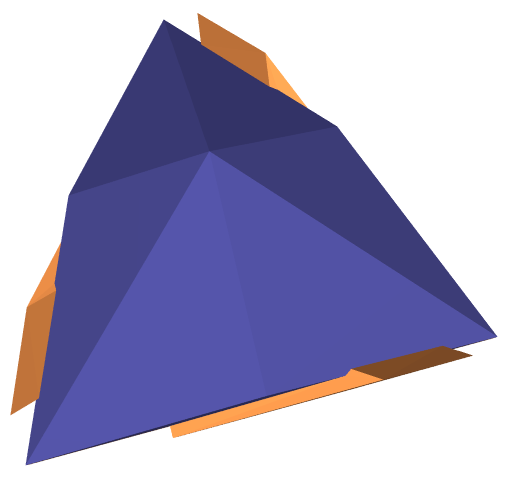
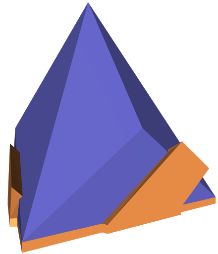
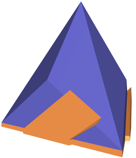
Figures 6a, 6b, and 6c depict a polyhedron and a fixture with three fingers that snaps onto . They demonstrate case I in Section 3. Here, we fix the base facet of the palm. It holds that for every possible fixture of with the fixed palm in the figures . To construct the polyhedron in the figures we start with a regular tetrahedron (such as the one depicted in Figure 3a), fix the bottom facet, subdivide each one of the remaining three facets into three identical triangles, and slightly translate the newly introduced vertex in the direction of the outer normal to the original facet, ensuring that the dihedral angle between the bottom facet and its neighbor remains acute.
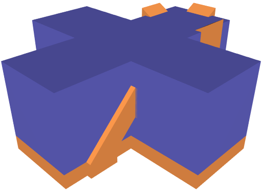
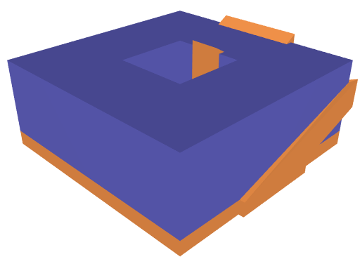

Figures 7a and 7b depict two polyhedra, and , and their snapping fixtures, respectively. They demonstrate case I in Section 3. The number of facets of each polyhedron is larger then six; however, it holds that for every possible fixture of , , where and is a covering set of the closed hemisphere .
There exists a polyhedron that does not have a valid fixture and the cardinality of the minimal covering set of is 6, where is the set of all facets of the polyhedron ; see the Figure 7c.
