Transmit MIMO Radar Beampattern Design Via Optimization on the Complex Circle Manifold

Khaled Alhujaili,  Vishal Monga,  and Muralidhar Rangaswamy,  K. Alhujaili is with the Department of Electrical Engineering, Pennsylvania State University, USA and also with the Department of Electrical Engineering, Taibah University, Al-Madina 344, Saudi Arabia. V. Monga is with the Department of Electrical Engineering, Pennsylvania State University, USA. M. Rangaswamy is with the RF Exploitation Branch, US Air Force Research Lab, Dayton, Ohio, USA. Dr. Rangaswamy was supported by the Air Force Office of Scientific Research under project 2311IN. Research was supported by a grant from the Air Force Office of Scientific Research (AFOSR) Award No. FA9550-15-1-0438.
Abstract

The ability of Multiple-Input Multiple-Output (MIMO) radar systems to adapt waveforms across antennas allows flexibility in the transmit beampattern design. In cognitive radar, a popular cost function is to minimize the deviation against an idealized beampattern (which is arrived at with knowledge of the environment). The optimization of the transmit beampattern becomes particularly challenging in the presence of practical constraints on the transmit waveform. One of the hardest of such constraints is the non-convex constant modulus constraint, which has been the subject of much recent work. In a departure from most existing approaches, we develop a solution that involves direct optimization over the non-convex complex circle manifold. That is, we derive a new projection, descent, and retraction (PDR) update strategy that allows for monotonic cost function improvement while maintaining feasibility over the complex circle manifold (constant modulus set). For quadratic cost functions (as is the case with beampattern deviation), we provide analytical guarantees of monotonic cost function improvement along with proof of convergence to a local minima. We evaluate the proposed PDR algorithm against other candidate MIMO beampattern design methods and show that PDR can outperform competing wideband beampattern design methods while being computationally less expensive. Finally, orthogonality across antennas is incorporated in the PDR framework by adding a penalty term to the beampattern cost function. Enabled by orthogonal waveforms, robustness to target direction mismatch is also demonstrated.

Index Terms:
MIMO radar, wideband beampattern, waveform design, constant modulus, complex circle manifold, manifolds, cognitive radar, PDR.

I Introduction

Multiple input multiple output (MIMO) radar, in general, transmits independent waveforms from its transmitting elements and observes the backscattered signals (from the target and from interference sources). On the other hand, in standard phased array radars, many small elements are employed so that each element emits an identical signal (up to a phase shift). These phases are shifted to focus the transmit beam in a certain direction [1]. The advantage of transmitting independent waveforms in MIMO radar provides extra degrees of freedom and the waveforms may be optimized across antennas to enhance the performance of radar systems.

A central problem in MIMO radar is to design a set of waveforms such that the transmitted beampattern matches certain specifications, e.g. a desired beampattern, either for narrowband [2, 3, 4, 5, 6] or wideband [7, 8, 9, 10, 11] setups. Although the transmit beampattern is used to focus the transmitted power in a certain directions of interest, a well-designed beampattern also helps enhance the Signal-to-Noise-Ratio (SNR)[2, 12, 13, 14]. While unconstrained design is straightforward, but this is a highly challenging problem in the presence of practical constraints on the waveform [15].

A principally important constraint on the transmit waveforms is the constant modulus constraint (CMC). The CMC is crucial in the design process due to the presence of non-linear amplifiers in radar systems [16] which must operate in saturation mode. Existing approaches that deal with beampattern design under CMC can be classified into two categories: indirect and direct approaches. The first category consists of methods that approximate or relax the CMC, i.e., the design process is conducted under approximated constraints and then the produced solution is converted to the constant modulus set. Examples in this category include: the peak-to-average ratio (PAR) waveform constraint [17], [8] and the energy constraint [18]. In general, since these approaches deal with an approximation of CMC, performance may degrade considerably in an actual real-world scenario when the constraint is strict [15]. In the second category are methods that directly enforce CMC and hence lead to better performance compared to the indirect approaches, but with relatively expensive computational procedures, such as a quasi Newton iterative method in [19], Semidefinite Relaxation (SDR) with randomization [20, 21] and the sequence of convex programs approach in [11].

In this work, our goal is to break the trade-off between performance measures such as faithfulness to the desired beampattern and computational complexity of designing/optimizing the waveform code. We show that this is possible by invoking principles of optimization over manifolds. That is, we derive a new projection, descent, and retraction (PDR) based numerical algorithm that in each iteration allows for monotonic cost function improvement while maintaining feasibility over the complex circle manifold (constant modulus set). Optimization over such a manifold has been investigated for problems in communications for example [22]. However, the work in [22] deals with an entirely different physical problem (and hence cost function) from ours and does not investigate analytical properties of the solution or convergence of the algorithm, which is a key focus of our work for quadratic loss functions.

Besides CMC, imposing orthogonality across antennas has been shown to be particularly meritorious. Orthogonal MIMO waveforms enable the radar system to achieve an increased virtual array [23, 14] and, hence leads to many practical benefits [24, 25, 26]. From a beampattern design standpoint, a compelling practical challenge is that the “directional knowledge” of target and interference sources utilized in specifying the desired beampattern may not be perfect. In such scenarios, it has been shown in [23, 14] that the gain loss in the transmit-receive patterns for orthogonal waveform transmission is very small under target direction mismatch.

Some work has been done towards the joint incorporation of CMC and orthogonality constraints [27, 28, 29, 30] under the umbrella of waveforms with desired auto-and-cross correlation properties. In these works, however, the beampattern is not designed but an outcome. Recently, in [31], a MIMO beampattern design that incorporates both CMC and orthogonality was investigated via a numerical approach based on the simulated annealing algorithm. To incorporate CMC, phase of the waveform vector is optimized numerically but analytical properties/guarantees of the solution are not investigated.

Our work addresses the aforementioned challenges in transmit MIMO beampattern design focusing particularly on tractable and scalable approaches in the presence of CMC. Specifically, our contributions include:

  • Projection, Descent and Retraction algorithm (PDR): A new approach is developed that works directly on the complex circle, i.e. descent is achieved while maintaining feasibility in the sense of CMC. The proposed numerical update consists of three steps: (1) Projection of the gradient of the cost function onto the tangent space of the complex circle manifold, i.e. the CMC set, (2) Descent on the tangent space (affine set), and (3) Retraction back to the complex circle.

  • Algorithm analysis and convergence guarantees: For quadratic cost functions, we formally prove that the cost function is monotonically decreasing while updating from one point to another on the complex circle and further convergence is guaranteed to a local minima.

  • Incorporating orthogonality: We show that the aforementioned PDR technique can be applied to enforce orthogonality across antennas by introducing an orthogonality encouraging penalty term with the cost function.

  • Numerical simulations insights and validation: We compare the PDR algorithm against the state-of-the-art approaches in MIMO beampattern design which address the CMC constraint. Results show that we can achieve better fidelity against a desired beampattern, at a remarkably lower computational cost. We also show that when orthogonality is incorporated, the PDR algorithm can achieve a beampattern design that exhibits robustness to target direction mismatch, which is hugely desirable in real-world scenarios where the specification of an idealized beampattern may not be exact.

The rest of the paper is organised as follows. The problem formulation is presented in Section II. In Section III, we provide a brief background on optimization over manifolds and develop the proposed PDR algorithm for beampattern design in the presence of the constant modulus constraint, equivalent to optimization over the complex circle manifold. New analytical results are provided in this setting that prove monotonic cost function improvement as well as convergence. Also presented in this section an extension towards incorporating the orthogonality constraint. Section IV compares and contrasts the proposed PDR algorithm against the state-of-the-art approaches in wideband transmit MIMO beampattern design. Concluding remarks and possible future research directions are discussed in Section V.

Notation: Nsuperscript𝑁\mathbb{C}^{N} and Nsuperscript𝑁\mathbb{R}^{N} denote the N𝑁N-dimensional complex and real vector spaces, respectively. We use boldface upper case for matrices and boldface lower case for vectors. 𝐱2subscriptnorm𝐱2\|\mathbf{x}\|_{2} is the 2-norm of the vector 𝐱𝐱\mathbf{x} and 𝐗Fsubscriptnorm𝐗𝐹\|\mathbf{X}\|_{F} is the Frobenius norm of the matrix 𝐗𝐗\mathbf{X}. The transpose, the conjugate, and the conjugate transpose (Hermitian) operators are denoted by (.)T(.)^{T}, (.)(.)^{*}, and (.)H(.)^{H} respectively. direct-product\odot and tensor-product\otimes denote the Hadamard and Kronecker product respectively. Re(.)\text{Re}(.) and Im(.)\text{Im}(.) denote extraction of the real part, and imaginary part of a complex number (or vector), respectively. |x|𝑥|x| denotes modulus of the complex number x𝑥x and |𝐱|𝐱|\mathbf{x}| is a vector of element wise absolute values of 𝐱𝐱\mathbf{x}, i.e., |𝐱|=[|x1||x2||xL|]T𝐱superscriptdelimited-[]subscript𝑥1subscript𝑥2subscript𝑥𝐿𝑇|\mathbf{x}|=\big{[}|x_{1}|\ |x_{2}|\ \ldots\ |x_{L}|\big{]}^{T}. 𝐬(f(𝐬))subscript𝐬𝑓𝐬\nabla_{\mathbf{s}}(f(\mathbf{s})) denotes the gradient of the function f𝑓f w.r.t. the vector 𝐬𝐬\mathbf{s}. vec(.)\text{vec}(.) denotes the vectorization operator. 𝐈Lsubscript𝐈𝐿\mathbf{I}_{L} is an L×L𝐿𝐿L\times L identity matrix. For matrices 𝐀𝐀\mathbf{A} and 𝐁𝐁\mathbf{B}, 𝐀𝐁𝐀𝐁0𝐀𝐁𝐀𝐁0\mathbf{A}\geq\mathbf{B}\Rightarrow\mathbf{A}-\mathbf{B}\geq 0, i.e., the matrix 𝐀𝐁𝐀𝐁\mathbf{A}-\mathbf{B} is positive-semi definite. 𝟙Msubscript1𝑀\mathbbm{1}_{M} denotes an M×M𝑀𝑀M\times M matrix with all ones. ddiag(𝐀)ddiag𝐀\text{ddiag}(\mathbf{A}) sets all off-diagonal entries of the matrix 𝐀𝐀\mathbf{A} to zero.

Refer to caption
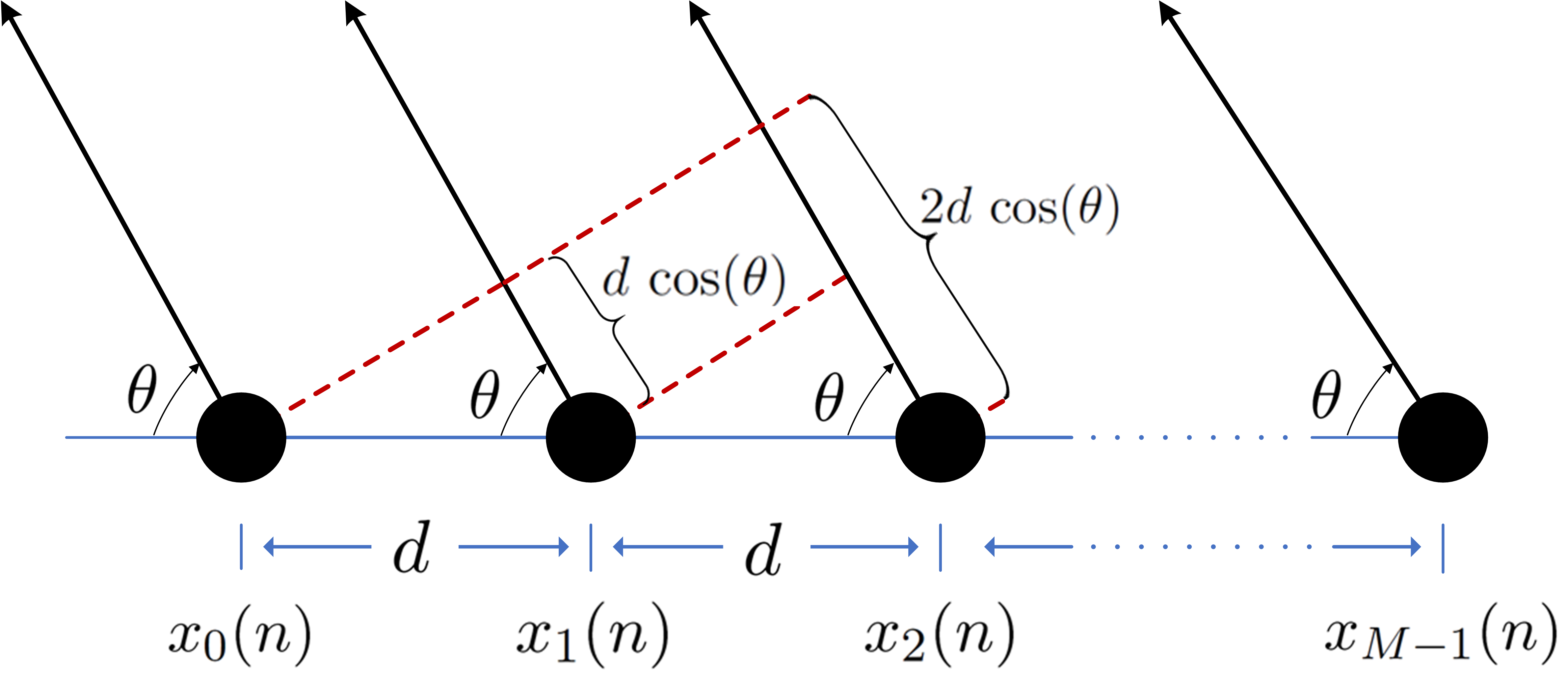
Figure 1: Uniform Linear Array (ULA) MIMO radar system

II Problem formulation

Consider a Uniform Linear Array (ULA) MIMO radar system that employs M𝑀M transmit antennas with inter-element spacing d𝑑d, as shown in Fig. 1. The transmitted bandpass signal transmitted by the mthsuperscript𝑚thm^{\text{th}} antenna is given by

sm(t)=xm(t)ej2πfctsubscript𝑠𝑚𝑡subscript𝑥𝑚𝑡superscript𝑒𝑗2𝜋subscript𝑓𝑐𝑡\displaystyle s_{m}(t)=x_{m}(t)\ e^{j2\pi f_{c}t} (1)

where fcsubscript𝑓𝑐f_{c} is the carrier frequency and xm(t)subscript𝑥𝑚𝑡x_{m}(t) is the baseband signal.

The baseband signal xm(t)subscript𝑥𝑚𝑡x_{m}(t) is sampled to N𝑁N samples with sampling rate Ts=1/Bsubscript𝑇𝑠1𝐵T_{s}=1/B and the samples are collected in the following vector

𝐱m=[xm(0)xm(1)xm(N1)]Tsubscript𝐱𝑚superscriptsubscript𝑥𝑚0subscript𝑥𝑚1subscript𝑥𝑚𝑁1𝑇\mathbf{x}_{m}=[x_{m}(0)\quad x_{m}(1)\quad...\quad x_{m}(N-1)]^{T} (2)

where xm(n)xm(t=nTs),n=0,1,,N1formulae-sequencesubscript𝑥𝑚𝑛subscript𝑥𝑚𝑡𝑛subscript𝑇𝑠𝑛01𝑁1x_{m}(n)\triangleq x_{m}(t=nT_{s}),\ n=0,1,\ldots,N-1, and B𝐵B is the bandwidth in Hz.

Let ym(p)subscript𝑦𝑚𝑝y_{m}(p) be the discrete Fourier Transform (DFT) of xm(n)subscript𝑥𝑚𝑛x_{m}(n) and expressed as:

ym(p)=n=0N1xm(n)ej2πnpN,p=N2,,0,,N21formulae-sequencesubscript𝑦𝑚𝑝superscriptsubscript𝑛0𝑁1subscript𝑥𝑚𝑛superscript𝑒𝑗2𝜋𝑛𝑝𝑁𝑝𝑁20𝑁21y_{m}(p)=\sum_{n=0}^{N-1}x_{m}(n)e^{-j2\pi\frac{np}{N}},\quad p=-\frac{N}{2},...,0,...,\frac{N}{2}-1 (3)

The discrete frequency beampattern in the far-field at spatial angle θ[0,180]𝜃superscript0superscript180\theta\in[0^{\circ},180^{\circ}] is [8]:

P(θ,p)=|𝐚H(θ,p)𝐲p|2𝑃𝜃𝑝superscriptsuperscript𝐚𝐻𝜃𝑝subscript𝐲𝑝2P(\theta,p)=|\mathbf{a}^{H}(\theta,p)\mathbf{y}_{p}|^{2} (4)

where 𝐚(θ,p)M×1𝐚𝜃𝑝superscript𝑀1\mathbf{a}(\theta,p)\in\mathbb{C}^{M\times 1} is the steering vector at frequency pNTs+fc𝑝𝑁subscript𝑇𝑠subscript𝑓𝑐\frac{p}{NT_{s}}+f_{c} defined as

\IEEEeqnarraymulticol3l𝐚(θ,p)=\IEEEeqnarraymulticol3𝑙𝐚𝜃𝑝absent\displaystyle\IEEEeqnarraymulticol{3}{l}{\mathbf{a}(\theta,p)=}
[1ej2π(pNTs+fc)dcosθcej2π(pNTs+fc)(M1)dcosθc]Tsuperscript1superscript𝑒𝑗2𝜋𝑝𝑁subscript𝑇𝑠subscript𝑓𝑐𝑑𝜃𝑐superscript𝑒𝑗2𝜋𝑝𝑁subscript𝑇𝑠subscript𝑓𝑐𝑀1𝑑𝜃𝑐𝑇\displaystyle\big{[}1\quad e^{j2\pi(\frac{p}{NT_{s}}+f_{c})\frac{d\cos\theta}{c}}\,...\,e^{j2\pi(\frac{p}{NT_{s}}+f_{c})\frac{(M-1)d\cos\theta}{c}}\big{]}^{T} (5)

and 𝐲p=[y0(p)y1(p)yM1(p)]Tsubscript𝐲𝑝superscriptsubscript𝑦0𝑝subscript𝑦1𝑝subscript𝑦𝑀1𝑝𝑇\mathbf{y}_{p}=[y_{0}(p)\quad y_{1}(p)\quad...\quad y_{M-1}(p)]^{T}.

Furthermore, the spatial angle θ𝜃\theta can be discretized by dividing the interval [0,180]superscript0superscript180[0^{\circ},180^{\circ}] into S𝑆S sub-intervals, i.e., {θs}s=1Ssuperscriptsubscriptsubscript𝜃𝑠𝑠1𝑆\{\theta_{s}\}_{s=1}^{S} and hence the steering vector 𝐚(θ,p)𝐚𝜃𝑝\mathbf{a}(\theta,p) can be written in terms of θssubscript𝜃𝑠\theta_{s} and p𝑝p as

𝐚sp=𝐚(θs,p),s=1,,Sformulae-sequencesubscript𝐚𝑠𝑝𝐚subscript𝜃𝑠𝑝𝑠1𝑆\mathbf{a}_{sp}=\mathbf{a}(\theta_{s},p),\ s=1,...,S

Using these notations, the beampattern in Eq (4) can be expressed in discrete angle-frequency as

Psp=|𝐚spH𝐲p|2=|𝐚spH𝐅p𝐱|2subscript𝑃𝑠𝑝superscriptsubscriptsuperscript𝐚𝐻𝑠𝑝subscript𝐲𝑝2superscriptsubscriptsuperscript𝐚𝐻𝑠𝑝subscript𝐅𝑝𝐱2P_{sp}=|\mathbf{a}^{H}_{sp}\mathbf{y}_{p}|^{2}=|\mathbf{a}^{H}_{sp}\mathbf{F}_{p}\mathbf{x}|^{2}

where 𝐱MN×1𝐱superscript𝑀𝑁1\mathbf{x}\in\mathbb{C}^{MN\times 1} is the concatenation of the waveforms vectors defined in Eq (2), i.e.,

𝐱=[𝐱0T𝐱1T𝐱M1T]T𝐱superscriptsubscriptsuperscript𝐱𝑇0subscriptsuperscript𝐱𝑇1subscriptsuperscript𝐱𝑇𝑀1𝑇\mathbf{x}=[\mathbf{x}^{T}_{0}\quad\mathbf{x}^{T}_{1}\quad...\quad\mathbf{x}^{T}_{M-1}]^{T} (6)

and 𝐅p=𝐞p𝐈Msubscript𝐅𝑝tensor-productsubscript𝐞𝑝subscript𝐈𝑀\mathbf{F}_{p}=\mathbf{e}_{p}\otimes\mathbf{I}_{M} where 𝐞p=[1ej2πpNej2π(N1)pN]subscript𝐞𝑝1superscript𝑒𝑗2𝜋𝑝𝑁superscript𝑒𝑗2𝜋𝑁1𝑝𝑁\mathbf{e}_{p}=[1\quad e^{-j2\pi\frac{p}{N}}\quad...\quad e^{-j2\pi\frac{(N-1)p}{N}}]. The beampattern design problem under constant modulus constraint can be formulated as

min𝐱s=1Sp=N2N21[dsp|𝐚spH𝐅p𝐱|]2s.t.: |𝐱|=𝟏subscript𝐱superscriptsubscript𝑠1𝑆superscriptsubscript𝑝𝑁2𝑁21superscriptdelimited-[]subscript𝑑𝑠𝑝subscriptsuperscript𝐚𝐻𝑠𝑝subscript𝐅𝑝𝐱2s.t.: 𝐱1\begin{array}[]{cc}\displaystyle\min_{\mathbf{x}}&\sum_{s=1}^{S}\sum_{p=-\frac{N}{2}}^{\frac{N}{2}-1}[d_{sp}-|\mathbf{a}^{H}_{sp}\mathbf{F}_{p}\mathbf{x}|]^{2}\\ \text{s.t.: }&|\mathbf{x}|=\mathbf{1}\par\end{array} (7)

where dspsubscript𝑑𝑠𝑝d_{sp}\in\mathbb{R} is the desired beampattern and the constant modulus constraint (|𝐱|=𝟏𝐱1|\mathbf{x}|=\mathbf{1}) implies that |xm(n)|=1subscript𝑥𝑚𝑛1|x_{m}(n)|=1 for m=0,1,,M𝑚01𝑀m=0,1,\ldots,M and n=0,1,,N𝑛01𝑁n=0,1,\ldots,N. We note that the a cost function in Eq (7) has been the focus of much past work [8, 9, 10, 11] with different ways of specifying dspsubscript𝑑𝑠𝑝d_{sp}.

Note that the cost function in Eq (7) is not tractable due to the |.||.| (absolute value) operator, this operator makes the function non-differentiable w.r.t. the variable 𝐱𝐱\mathbf{x}. To overcome this issue, it has been shown in [8] that for a generic term [dsp|𝐚spH𝐅p𝐱|]2superscriptdelimited-[]subscript𝑑𝑠𝑝subscriptsuperscript𝐚𝐻𝑠𝑝subscript𝐅𝑝𝐱2[d_{sp}-|\mathbf{a}^{H}_{sp}\mathbf{F}_{p}\mathbf{x}|]^{2} of Eq (7), the following holds

minϕsp|dspejϕsp𝐚spH𝐅p𝐱|2=minϕsp{dsp2+|𝐚spH𝐅p𝐱|22Re[dsp|𝐚spH𝐅p𝐱|cos(ϕsparg(𝐚spH𝐅p𝐱))]}=[dsp|𝐚spH𝐅p𝐱|]2(forϕsp=arg{𝐚spH𝐅p𝐱})formulae-sequencesubscriptsubscriptitalic-ϕ𝑠𝑝superscriptsubscript𝑑𝑠𝑝superscript𝑒𝑗subscriptitalic-ϕ𝑠𝑝subscriptsuperscript𝐚𝐻𝑠𝑝subscript𝐅𝑝𝐱2subscriptsubscriptitalic-ϕ𝑠𝑝superscriptsubscript𝑑𝑠𝑝2superscriptsubscriptsuperscript𝐚𝐻𝑠𝑝subscript𝐅𝑝𝐱22Redelimited-[]subscript𝑑𝑠𝑝subscriptsuperscript𝐚𝐻𝑠𝑝subscript𝐅𝑝𝐱cossubscriptitalic-ϕ𝑠𝑝argsubscriptsuperscript𝐚𝐻𝑠𝑝subscript𝐅𝑝𝐱superscriptdelimited-[]subscript𝑑𝑠𝑝subscriptsuperscript𝐚𝐻𝑠𝑝subscript𝐅𝑝𝐱2forsubscriptitalic-ϕ𝑠𝑝subscriptsuperscript𝐚𝐻𝑠𝑝subscript𝐅𝑝𝐱\begin{split}&\min_{\mathbf{\phi}_{sp}}|d_{sp}e^{j\phi_{sp}}-\mathbf{a}^{H}_{sp}\mathbf{F}_{p}\mathbf{x}|^{2}\\ &=\min_{\mathbf{\phi}_{sp}}\Big{\{}d_{sp}^{2}+|\mathbf{a}^{H}_{sp}\mathbf{F}_{p}\mathbf{x}|^{2}\\ &\ \ \ -2\text{Re}[d_{sp}|\mathbf{a}^{H}_{sp}\mathbf{F}_{p}\mathbf{x}|\text{cos}(\phi_{sp}-\text{arg}(\mathbf{a}^{H}_{sp}\mathbf{F}_{p}\mathbf{x}))]\Big{\}}\\ &=[d_{sp}-|\mathbf{a}^{H}_{sp}\mathbf{F}_{p}\mathbf{x}|]^{2}\ \ (\text{for}\ \phi_{sp}=\arg\{\mathbf{a}^{H}_{sp}\mathbf{F}_{p}\mathbf{x}\})\end{split} (8)

In view of the above, the authors in [8] formulate the following problem over ϕspsubscriptitalic-ϕ𝑠𝑝\phi_{sp} and 𝐱𝐱\mathbf{x} jointly

min𝐱,{ϕsp}s,pf(𝐱)=s=1Sp=N2N21|dspejϕsp𝐚spH𝐅p𝐱|2s.t.: |𝐱|=𝟏subscript𝐱subscriptsubscriptitalic-ϕ𝑠𝑝for-all𝑠𝑝𝑓𝐱superscriptsubscript𝑠1𝑆superscriptsubscript𝑝𝑁2𝑁21superscriptsubscript𝑑𝑠𝑝superscript𝑒𝑗subscriptitalic-ϕ𝑠𝑝subscriptsuperscript𝐚𝐻𝑠𝑝subscript𝐅𝑝𝐱2s.t.: 𝐱1\begin{array}[]{cc}\displaystyle\min_{\mathbf{x},\{\phi_{sp}\}_{\forall s,p}}&f(\mathbf{x})=\sum_{s=1}^{S}\sum_{p=-\frac{N}{2}}^{\frac{N}{2}-1}|d_{sp}e^{j\phi_{sp}}-\mathbf{a}^{H}_{sp}\mathbf{F}_{p}\mathbf{x}|^{2}\\ \text{s.t.: }&|\mathbf{x}|=\mathbf{1}\end{array} (9)

With this form, the beampattern design problem will be carried out over two minimization stages: one w.r.t. ϕspsubscriptitalic-ϕ𝑠𝑝\phi_{sp} for fixed 𝐱𝐱\mathbf{x} with a minimizer ϕsp=arg{𝐚spH𝐅p𝐱}subscriptitalic-ϕ𝑠𝑝subscriptsuperscript𝐚𝐻𝑠𝑝subscript𝐅𝑝𝐱\phi_{sp}=\arg\{\mathbf{a}^{H}_{sp}\mathbf{F}_{p}\mathbf{x}\} and the second one will be w.r.t. 𝐱𝐱\mathbf{x} for fixed ϕspsubscriptitalic-ϕ𝑠𝑝\phi_{sp}. It is worthwhile observing that the phase variable ϕspsubscriptitalic-ϕ𝑠𝑝\phi_{sp} is not inherent to the problem but introduced to make the problem tractable, i.e., when the phases of dspejϕspsubscript𝑑𝑠𝑝superscript𝑒𝑗subscriptitalic-ϕ𝑠𝑝d_{sp}e^{j\phi_{sp}} and 𝐚spH𝐅p𝐱subscriptsuperscript𝐚𝐻𝑠𝑝subscript𝐅𝑝𝐱\mathbf{a}^{H}_{sp}\mathbf{F}_{p}\mathbf{x} agree, the cost function is a quadratic w.r.t. 𝐱𝐱\mathbf{x}. Therefore, in this work, we are seeking to optimize f(𝐱)𝑓𝐱f(\mathbf{x}) w.r.t. 𝐱𝐱\mathbf{x} for fixed ϕspsubscriptitalic-ϕ𝑠𝑝\phi_{sp} under CMC.

Then, the cost function in problem (9) can be rewritten compactly, with fixed ϕspsubscriptitalic-ϕ𝑠𝑝\phi_{sp}, as:

f(𝐱)𝑓𝐱\displaystyle f(\mathbf{x}) =\displaystyle= p𝐝p𝐀p𝐅p𝐱22subscript𝑝superscriptsubscriptnormsubscript𝐝𝑝subscript𝐀𝑝subscript𝐅𝑝𝐱22\displaystyle\sum_{p}\|\mathbf{d}_{p}-\mathbf{A}_{p}\mathbf{F}_{p}\mathbf{x}\|_{2}^{2} (10)
=\displaystyle= p𝐱H𝐅pH𝐀pH𝐀p𝐅p𝐱𝐝pH𝐀p𝐅p𝐱𝐱H𝐅pH𝐀pH𝐝psubscript𝑝superscript𝐱𝐻subscriptsuperscript𝐅𝐻𝑝subscriptsuperscript𝐀𝐻𝑝subscript𝐀𝑝subscript𝐅𝑝𝐱subscriptsuperscript𝐝𝐻𝑝subscript𝐀𝑝subscript𝐅𝑝𝐱superscript𝐱𝐻subscriptsuperscript𝐅𝐻𝑝subscriptsuperscript𝐀𝐻𝑝subscript𝐝𝑝\displaystyle\ \sum_{p}\mathbf{x}^{H}\mathbf{F}^{H}_{p}\mathbf{A}^{H}_{p}\mathbf{A}_{p}\mathbf{F}_{p}\mathbf{x}-\mathbf{d}^{H}_{p}\mathbf{A}_{p}\mathbf{F}_{p}\mathbf{x}-\mathbf{x}^{H}\mathbf{F}^{H}_{p}\mathbf{A}^{H}_{p}\mathbf{d}_{p}
+p𝐝pH𝐝psubscript𝑝superscriptsubscript𝐝𝑝𝐻subscript𝐝𝑝\displaystyle+\>\sum_{p}\mathbf{d}_{p}^{H}\mathbf{d}_{p}
=\displaystyle= 𝐱H𝐏𝐱𝐪H𝐱𝐱H𝐪+rsuperscript𝐱𝐻𝐏𝐱superscript𝐪𝐻𝐱superscript𝐱𝐻𝐪𝑟\displaystyle\mathbf{x}^{H}\mathbf{P}\mathbf{x}-\mathbf{q}^{H}\mathbf{x}-\mathbf{x}^{H}\mathbf{q}+r

where

𝐀p=[𝐚1pH𝐚SpH],𝐝p=[d1pejϕ1pdSpejϕSp],formulae-sequencesubscript𝐀𝑝matrixsubscriptsuperscript𝐚𝐻1𝑝subscriptsuperscript𝐚𝐻𝑆𝑝subscript𝐝𝑝matrixsubscript𝑑1𝑝superscript𝑒𝑗subscriptitalic-ϕ1𝑝subscript𝑑𝑆𝑝superscript𝑒𝑗subscriptitalic-ϕ𝑆𝑝\mathbf{A}_{p}={\begin{bmatrix}\mathbf{a}^{H}_{1p}\\ \vdots\\ \mathbf{a}^{H}_{Sp}\end{bmatrix}},\quad\mathbf{d}_{p}={\begin{bmatrix}d_{1p}e^{j\phi_{1p}}\\ \vdots\\ d_{Sp}e^{j\phi_{Sp}}\end{bmatrix}},

and 𝐏=p𝐅pH𝐀pH𝐀p𝐅p𝐏subscript𝑝subscriptsuperscript𝐅𝐻𝑝subscriptsuperscript𝐀𝐻𝑝subscript𝐀𝑝subscript𝐅𝑝\mathbf{P}=\sum_{p}\mathbf{F}^{H}_{p}\mathbf{A}^{H}_{p}\mathbf{A}_{p}\mathbf{F}_{p}, 𝐪=p𝐅pH𝐀pH𝐝p𝐪subscript𝑝subscriptsuperscript𝐅𝐻𝑝subscriptsuperscript𝐀𝐻𝑝subscript𝐝𝑝\mathbf{q}=\sum_{p}\mathbf{F}^{H}_{p}\mathbf{A}^{H}_{p}\mathbf{d}_{p} and r=p𝐝pH𝐝p𝑟subscript𝑝superscriptsubscript𝐝𝑝𝐻subscript𝐝𝑝r=\sum_{p}\mathbf{d}_{p}^{H}\mathbf{d}_{p}. Consequently, the problem in (9) is reframed as

min𝐱f(𝐱)=𝐱H𝐏𝐱𝐪H𝐱𝐱H𝐪+rs.t.: |𝐱|=𝟏subscript𝐱𝑓𝐱superscript𝐱𝐻𝐏𝐱superscript𝐪𝐻𝐱superscript𝐱𝐻𝐪𝑟s.t.: 𝐱1\begin{array}[]{cc}\displaystyle\min_{\mathbf{x}}&f(\mathbf{x})=\mathbf{x}^{H}\mathbf{P}\mathbf{x}-\mathbf{q}^{H}\mathbf{x}-\mathbf{x}^{H}\mathbf{q}+r\\ \text{s.t.: }&|\mathbf{x}|=\mathbf{1}\end{array} (11)

This optimization problem is known to be a hard non-convex NP-hard problem [32]. Some of the best known methods that develop a solution for this form are: Wideband Beampattern Formation via Iterative Techniques (WBFIT) [8], Semi-Definite relaxation with Randomization (SDR) [20, 21], the Monotonically Error-bound Improving Technique (MERIT) [32], the Iterative Algorithm for Continuous Phase Case (IA-CPC) [33], design algorithm based on Alternating Direction Method of Multipliers (ADMM) [34]. Some of these approaches suffer from low performance accuracy (in terms of deviation from the desired beampattern) while others involve relatively expensive computational procedures. Importantly, CMC is extracted in different parts of the optimization or in some other methods approached asymptotically [11], but a direct optimization over the non-convex CMC remains elusive.

We take a drastically different approach by invoking principles of optimization over non-convex manifolds. Our focus is on developing a gradient based method, which can enable descent on the complex circle manifold (formal manifold terminology for the CMC) while maintaining feasibility.

Before describing our solution in the next Section, we make an alteration to the cost function by adding γ𝐱H𝐱𝛾superscript𝐱𝐻𝐱\gamma\mathbf{x}^{H}\mathbf{x}:

min𝐱Lf¯(𝐱)=𝐱H(𝐏+γ𝐈)𝐱𝐪H𝐱𝐱H𝐪s.t.: |𝐱|=𝟏subscript𝐱superscript𝐿¯𝑓𝐱superscript𝐱𝐻𝐏𝛾𝐈𝐱superscript𝐪𝐻𝐱superscript𝐱𝐻𝐪s.t.: 𝐱1\begin{array}[]{cc}\displaystyle\min_{\mathbf{x}\in\mathbb{C}^{L}}&\bar{f}(\mathbf{x})=\mathbf{x}^{H}(\mathbf{P}+\gamma\mathbf{I})\mathbf{x}-\mathbf{q}^{H}\mathbf{x}-\mathbf{x}^{H}\mathbf{q}\\ \text{s.t.: }&|\mathbf{x}|=\mathbf{1}\\ \end{array} (12)

where L=MN𝐿𝑀𝑁L=MN, and γ0𝛾0\gamma\geq 0 (it will be used later in Lemma III.2 to control convergence). Since the problem in (12) enforces CMC, the term γ𝐱H𝐱𝛾superscript𝐱𝐻𝐱\gamma\mathbf{x}^{H}\mathbf{x} is constant (i.e. γ𝐱H𝐱=γL𝛾superscript𝐱𝐻𝐱𝛾𝐿\gamma\mathbf{x}^{H}\mathbf{x}=\gamma L). Hence, the optimal solution of the problem in (11) and the optimal solution of the problem in (12) are identical for any γ0𝛾0\gamma\geq 0.

III Constant modulus constraint and optimization over manifolds

The search space or the feasible set of the problem in (12) can be thought of as the product of L𝐿L (complex) circles, i.e.,

𝒮×𝒮×𝒮Ltimessubscript𝒮𝒮𝒮𝐿times\underbrace{\mathcal{S}\times\mathcal{S}\ldots\times\mathcal{S}}_{L\ \text{times}}

where 𝒮𝒮\mathcal{S} is one (complex) circle which is defined as 𝒮={x:xx=Re{x}2+Im{x}2=1}𝒮conditional-set𝑥superscript𝑥𝑥Resuperscript𝑥2Imsuperscript𝑥21\mathcal{S}\overset{\triangle}{=}\{x\in\mathbb{C}:x^{*}x=\text{Re}\{x\}^{2}+\text{Im}\{x\}^{2}=1\}. This set (𝒮𝒮\mathcal{S}) can be seen as a sub-manifold of \mathbb{C} [35] and hence, the product of such L𝐿L circles is a sub-manifold of Lsuperscript𝐿\mathbb{C}^{L} [35]. This manifold is known as the complex circle manifold and defined as

𝒮L={𝐱L:|xl|=1,l=1,2,,L}superscript𝒮𝐿conditional-set𝐱superscript𝐿formulae-sequencesubscript𝑥𝑙1𝑙12𝐿\mathcal{S}^{L}\overset{\triangle}{=}\{\mathbf{x}\in\mathbb{C}^{L}:|x_{l}|=1,\ l=1,2,\ldots,L\} (13)

Before we proceed with the solution of the optimization problem in (12), we first provide a background on optimization over manifolds [36] and subsequently develop a new technique to optimize directly over the complex circle manifold.

III-A Optimization over manifolds

The term optimization over manifolds refers to a class of problems of the form

min𝐱𝐱min\displaystyle\underset{\mathbf{x}\in\mathcal{M}}{\text{min}} g(𝐱)𝑔𝐱\displaystyle g(\mathbf{x}) (14)

where g(𝐱)𝑔𝐱g(\mathbf{x}) is a smooth real-valued function and \mathcal{M} is some manifold. Many classical line-search algorithms from unconstrained nonlinear optimization in Lsuperscript𝐿\mathbb{C}^{L} such as gradient descent can be used in optimization over manifolds but with some modifications. In general, line-search methods in Lsuperscript𝐿\mathbb{C}^{L} are based on the following update formula

𝐱(k+1)=𝐱(k)+βk𝜼(k)subscript𝐱𝑘1subscript𝐱𝑘subscript𝛽𝑘subscript𝜼𝑘\mathbf{x}_{(k+1)}=\mathbf{x}_{(k)}+\beta_{k}\boldsymbol{\eta}_{(k)} (15)

where 𝜼(k)Lsubscript𝜼𝑘superscript𝐿\boldsymbol{\eta}_{(k)}\in\mathbb{C}^{L} is the search direction and βksubscript𝛽𝑘\beta_{k}\in\mathbb{R} is the step size. The most obvious choice for the search direction is the steepest descent direction which is the negative gradient of g(𝐱)𝑔𝐱g(\mathbf{x}), i.e., 𝜼(k)=𝐱g(𝐱(k))subscript𝜼𝑘subscript𝐱𝑔subscript𝐱𝑘\boldsymbol{\eta}_{(k)}=-\nabla_{\mathbf{x}}g(\mathbf{x}_{(k)}). In the literature [36, 37], the following high level structure is suggested:

  • The descent will be performed on the manifold itself rather than in the Euclidean space by means of the intrinsic gradient. The intrinsic gradient g(𝐱(k))subscript𝑔subscript𝐱𝑘\nabla_{\mathcal{M}}g(\mathbf{x}_{(k)}) of g(𝐱)𝑔𝐱g(\mathbf{x}) at point 𝐱(k)subscript𝐱𝑘\mathbf{x}_{(k)}\in\mathcal{M} is a vector in the tangent space 𝒯𝐱(k)subscript𝒯subscript𝐱𝑘\mathcal{T}_{\mathbf{x}_{(k)}}\mathcal{M} (for the definition of 𝒯𝐱(k)subscript𝒯subscript𝐱𝑘\mathcal{T}_{\mathbf{x}_{(k)}}\mathcal{M}, see [36], Section 3.5.7). This intrinsic gradient can be obtained by projecting the standard (Euclidean) gradient 𝐱g(𝐱(k))subscript𝐱𝑔subscript𝐱𝑘\nabla_{\mathbf{x}}g(\mathbf{x}_{(k)}) onto 𝒯𝐱(k)subscript𝒯subscript𝐱𝑘\mathcal{T}_{\mathbf{x}_{(k)}}\mathcal{M} by means of a projection operator 𝐏𝒯𝐱(k)(𝐱g(𝐱(k)))subscript𝐏subscript𝒯subscript𝐱𝑘subscript𝐱𝑔subscript𝐱𝑘\mathbf{P}_{\mathcal{T}_{\mathbf{x}_{(k)}}\mathcal{M}}\big{(}\nabla_{\mathbf{x}}g(\mathbf{x}_{(k)})\big{)}.

  • The update is performed on the tangent space along the direction of 𝐏𝒯𝐱(k)(𝐱g(𝐱(k)))subscript𝐏subscript𝒯subscript𝐱𝑘subscript𝐱𝑔subscript𝐱𝑘\mathbf{P}_{\mathcal{T}_{\mathbf{x}_{(k)}}\mathcal{M}}\big{(}\nabla_{\mathbf{x}}g(\mathbf{x}_{(k)})\big{)} with a step β𝛽\beta, i.e., 𝐱¯(k)=𝐱(k)β𝐏𝒯𝐱(k)(𝐱g(𝐱(k)))subscript¯𝐱𝑘subscript𝐱𝑘𝛽subscript𝐏subscript𝒯subscript𝐱𝑘subscript𝐱𝑔subscript𝐱𝑘\bar{\mathbf{x}}_{(k)}=\mathbf{x}_{(k)}-\beta\mathbf{P}_{\mathcal{T}_{\mathbf{x}_{(k)}}\mathcal{M}}(\nabla_{\mathbf{x}}g(\mathbf{x}_{(k)})) where 𝐱¯(k)𝒯𝐱(k)subscript¯𝐱𝑘subscript𝒯subscript𝐱𝑘\bar{\mathbf{x}}_{(k)}\in\mathcal{T}_{\mathbf{x}_{(k)}}\mathcal{M}.

  • Since 𝐱¯(k)subscript¯𝐱𝑘\bar{\mathbf{x}}_{(k)}\notin\mathcal{M}, it will be mapped back to the manifold by the means of a retraction operator, 𝐱(k+1)=𝐑(𝐱¯(k))subscript𝐱𝑘1𝐑subscript¯𝐱𝑘\mathbf{x}_{(k+1)}=\mathbf{R}\big{(}\bar{\mathbf{x}}_{(k)}\big{)}.

For some manifolds, the projection 𝐏𝒯𝐱(k)(.)\mathbf{P}_{\mathcal{T}_{\mathbf{x}_{(k)}}\mathcal{M}}(.) and retraction 𝐑(.)\mathbf{R}(.) operators admit a closed form. Interested readers may refer to [36] for details. In the following subsections, we develop new results that employ the ideas articulated above in optimization over manifolds to the complex circle manifold (constant modulus set), i.e., =𝒮Lsuperscript𝒮𝐿\mathcal{M}=\mathcal{S}^{L}. In particular, 1) we derive expressions for the projection and retraction operators for the complex circle manifold 𝒮Lsuperscript𝒮𝐿\mathcal{S}^{L}, 2) establish new analytical results which include proof of monotonic cost function improvement while maintaining feasibility in 𝒮Lsuperscript𝒮𝐿\mathcal{S}^{L}, and 3) provide convergence guarantees.

III-B Complex circle manifold

The projection and retraction operators for the complex circle manifold are inspired by those for the unit circle manifold [36], which is defined as

𝒞1={𝐪2:𝐪T𝐪=1}superscript𝒞1conditional-set𝐪superscript2superscript𝐪𝑇𝐪1\mathcal{C}^{1}\overset{\triangle}{=}\{\mathbf{q}\in\mathbb{R}^{2}:\mathbf{q}^{T}\mathbf{q}=1\} (16)

That is true because each entry of any feasible vector 𝐱𝒮L𝐱superscript𝒮𝐿\mathbf{x}\in\mathcal{S}^{L} can be viewed as a point in 2superscript2\mathbb{R}^{2} with its components on the (real) unit-circle (𝒞1superscript𝒞1\mathcal{C}^{1}). Thus, in order to derive these operators for the complex circle manifold we need to start with the operators for the unit circle manifold.

First, let us define the following two vectors 𝐳𝒮L𝐳superscript𝒮𝐿\mathbf{z}\in\mathcal{S}^{L} and 𝐰L𝐰superscript𝐿\mathbf{w}\in\mathbb{C}^{L}, and let 𝐳¯lsubscript¯𝐳𝑙\bar{\mathbf{z}}_{l} and 𝐰¯lsubscript¯𝐰𝑙\bar{\mathbf{w}}_{l} be 2-dimensional vectors represent the components of the lthsuperscript𝑙thl^{\text{th}} element of 𝐳𝐳\mathbf{z} and 𝐰𝐰\mathbf{w} respectively, i.e.,

  • 𝐳¯l=[Re{zl}Im{zl}]T=[zlrzli]T2subscript¯𝐳𝑙superscriptdelimited-[]Resubscript𝑧𝑙Imsubscript𝑧𝑙𝑇superscriptdelimited-[]subscript𝑧𝑙𝑟subscript𝑧𝑙𝑖𝑇superscript2\bar{\mathbf{z}}_{l}=[\text{Re}\{z_{l}\}\ \text{Im}\{z_{l}\}]^{T}=[z_{lr}\ z_{li}]^{T}\in\mathbb{R}^{2}

  • 𝐰¯l=[Re{wl}Im{wl}]T=[wlrwli]T2subscript¯𝐰𝑙superscriptdelimited-[]Resubscript𝑤𝑙Imsubscript𝑤𝑙𝑇superscriptdelimited-[]subscript𝑤𝑙𝑟subscript𝑤𝑙𝑖𝑇superscript2\bar{\mathbf{w}}_{l}=[\text{Re}\{w_{l}\}\ \text{Im}\{w_{l}\}]^{T}=[w_{lr}\ w_{li}]^{T}\in\mathbb{R}^{2}

where l=1,2,,L𝑙12𝐿l=1,2,\ldots,L. Note that since the vector 𝐳𝒮L𝐳superscript𝒮𝐿\mathbf{z}\in\mathcal{S}^{L}, then the vector 𝐳¯l𝒞1subscript¯𝐳𝑙superscript𝒞1\bar{\mathbf{z}}_{l}\in\mathcal{C}^{1}, i.e., 𝐳¯lT𝐳¯l=1superscriptsubscript¯𝐳𝑙𝑇subscript¯𝐳𝑙1\bar{\mathbf{z}}_{l}^{T}\bar{\mathbf{z}}_{l}=1.

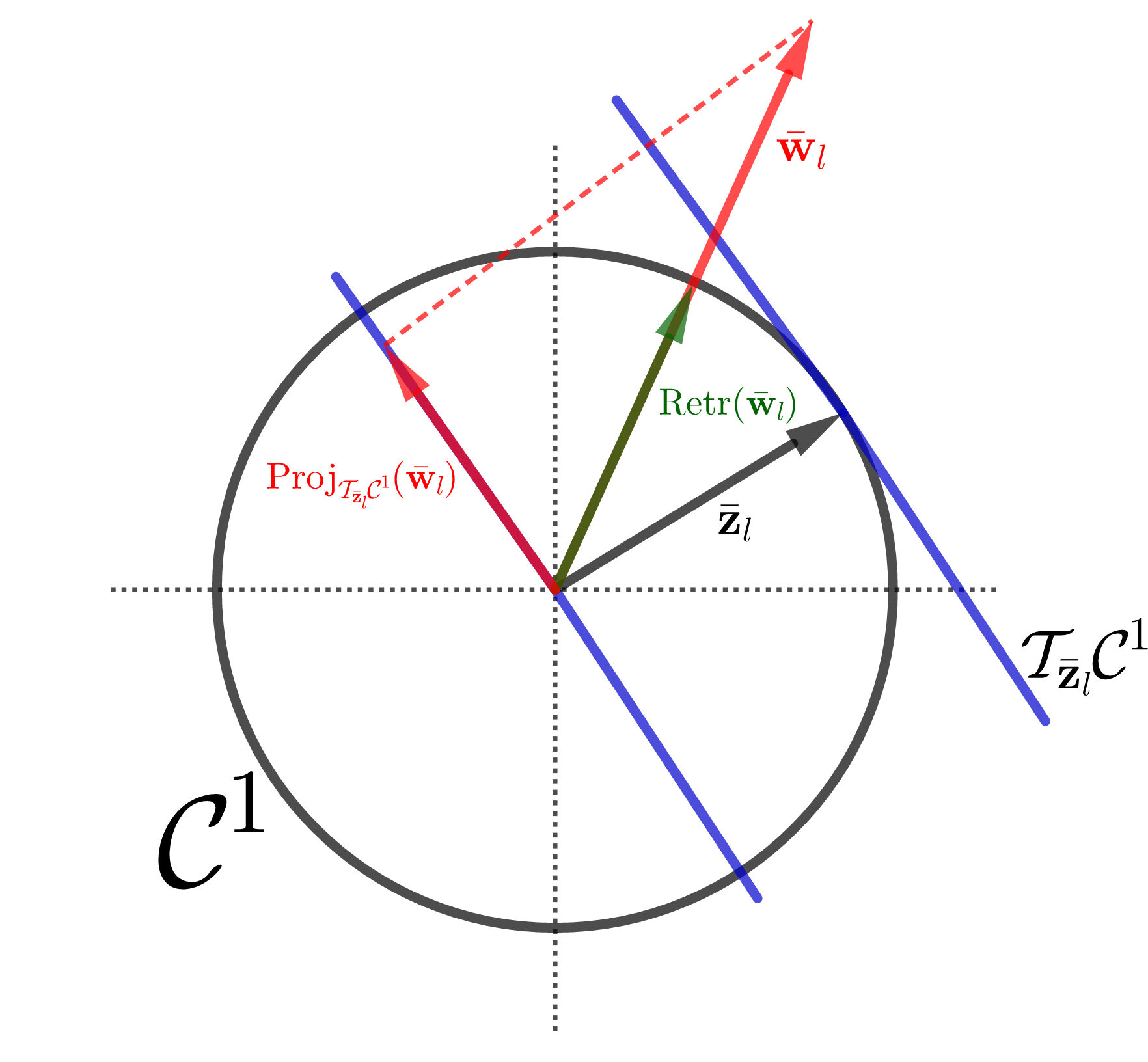
The projection of 𝐰¯l2subscript¯𝐰𝑙superscript2\bar{\mathbf{w}}_{l}\in\mathbb{R}^{2} to the tangent space of the unit circle manifold111The tangent space for unit circle manifold at 𝐪𝒞1𝐪superscript𝒞1\mathbf{q}\in\mathcal{C}^{1} is defined as 𝒯𝐪𝒞1={𝐡2:𝐪T𝐡=0}subscript𝒯𝐪superscript𝒞1conditional-set𝐡superscript2superscript𝐪𝑇𝐡0\mathcal{T}_{\mathbf{q}}\mathcal{C}^{1}=\{\mathbf{h}\in\mathbb{R}^{2}:\mathbf{q}^{T}\mathbf{h}=0\}[36]. 𝒯𝐳¯l𝒞1subscript𝒯subscript¯𝐳𝑙superscript𝒞1\mathcal{T}_{\bar{\mathbf{z}}_{l}}\mathcal{C}^{1} at 𝐳¯lsubscript¯𝐳𝑙\bar{\mathbf{z}}_{l} is given by [36]:

Proj𝒯𝐳¯l𝒞1(𝐰¯l)subscriptProjsubscript𝒯subscript¯𝐳𝑙superscript𝒞1subscript¯𝐰𝑙\displaystyle\text{Proj}_{\mathcal{T}_{\bar{\mathbf{z}}_{l}}\mathcal{C}^{1}}(\bar{\mathbf{w}}_{l}) =\displaystyle= 𝐰¯l𝐳¯lT𝐰¯l𝐳¯lsubscript¯𝐰𝑙superscriptsubscript¯𝐳𝑙𝑇subscript¯𝐰𝑙subscript¯𝐳𝑙\displaystyle\bar{\mathbf{w}}_{l}-\bar{\mathbf{z}}_{l}^{T}\bar{\mathbf{w}}_{l}\bar{\mathbf{z}}_{l} (17)
=\displaystyle= 𝐰¯l(wlrzlr+wlizli)𝐳¯lsubscript¯𝐰𝑙subscript𝑤𝑙𝑟subscript𝑧𝑙𝑟subscript𝑤𝑙𝑖subscript𝑧𝑙𝑖subscript¯𝐳𝑙\displaystyle\bar{\mathbf{w}}_{l}-(w_{lr}z_{lr}+w_{li}z_{li})\bar{\mathbf{z}}_{l}
=\displaystyle= 𝐰¯lRe{wlzl}𝐳¯lsubscript¯𝐰𝑙Resuperscriptsubscript𝑤𝑙subscript𝑧𝑙subscript¯𝐳𝑙\displaystyle\bar{\mathbf{w}}_{l}-\text{Re}\{w_{l}^{*}z_{l}\}\bar{\mathbf{z}}_{l}
=\displaystyle= [wlrRe{wlzl}zlrwliRe{wlzl}zli]2matrixsubscript𝑤𝑙𝑟Resuperscriptsubscript𝑤𝑙subscript𝑧𝑙subscript𝑧𝑙𝑟subscript𝑤𝑙𝑖Resuperscriptsubscript𝑤𝑙subscript𝑧𝑙subscript𝑧𝑙𝑖superscript2\displaystyle{\begin{bmatrix}w_{lr}-\text{Re}\{w_{l}^{*}z_{l}\}z_{lr}\\ w_{li}-\text{Re}\{w_{l}^{*}z_{l}\}z_{li}\\ \end{bmatrix}}\in\mathbb{R}^{2}

and the retraction of any 𝐰¯l2subscript¯𝐰𝑙superscript2\bar{\mathbf{w}}_{l}\in\mathbb{R}^{2} to 𝒞1superscript𝒞1\mathcal{C}^{1} is given by [36]

Ret(𝐰¯l)Retsubscript¯𝐰𝑙\displaystyle\text{Ret}(\bar{\mathbf{w}}_{l}) =\displaystyle= 𝐰¯l𝐰¯l2subscript¯𝐰𝑙subscriptnormsubscript¯𝐰𝑙2\displaystyle\frac{\bar{\mathbf{w}}_{l}}{\|\bar{\mathbf{w}}_{l}\|_{2}} (18)
=\displaystyle= [wlrwlr2+wli2wliwlr2+wli2]T𝒞1superscriptdelimited-[]subscript𝑤𝑙𝑟superscriptsubscript𝑤𝑙𝑟2superscriptsubscript𝑤𝑙𝑖2subscript𝑤𝑙𝑖superscriptsubscript𝑤𝑙𝑟2superscriptsubscript𝑤𝑙𝑖2𝑇superscript𝒞1\displaystyle\Bigg{[}\frac{w_{lr}}{\sqrt{w_{lr}^{2}+w_{li}^{2}}}\ \frac{w_{li}}{\sqrt{w_{lr}^{2}+w_{li}^{2}}}\Bigg{]}^{T}\in\mathcal{C}^{1}

These operators for projecting 𝐰¯lsubscript¯𝐰𝑙\bar{\mathbf{w}}_{l} onto 𝒯𝐳¯l𝒞1subscript𝒯subscript¯𝐳𝑙superscript𝒞1\mathcal{T}_{\bar{\mathbf{z}}_{l}}\mathcal{C}^{1} and retracting it to 𝒞1superscript𝒞1\mathcal{C}^{1} are illustrated in Fig. 2.

Refer to caption
Figure 2: Projection Proj𝐳¯l(𝐰¯l)subscriptProjsubscript¯𝐳𝑙subscript¯𝐰𝑙\text{Proj}_{\bar{\mathbf{z}}_{l}}(\bar{\mathbf{w}}_{l}) and retraction Retr(𝐰¯l)Retrsubscript¯𝐰𝑙\text{Retr}(\bar{\mathbf{w}}_{l}) operators in 𝒞1superscript𝒞1\mathcal{C}^{1}.

According to our discussion at the beginning of this subsection, the relation between the projection of wlsubscript𝑤𝑙w_{l} onto the tangent space222The tangent space of 𝒮𝒮\mathcal{S} at the point zl𝒮subscript𝑧𝑙𝒮z_{l}\in\mathcal{S} is defined as [35] 𝒯zl𝒮={y:Re{yzl}=0}subscript𝒯subscript𝑧𝑙𝒮conditional-set𝑦Resuperscript𝑦subscript𝑧𝑙0\mathcal{T}_{z_{l}}\mathcal{S}=\{y\in\mathbb{C}:\text{Re}\{y^{*}z_{l}\}=0\} 𝒯zl𝒮subscript𝒯subscript𝑧𝑙𝒮\mathcal{T}_{z_{l}}\mathcal{S} and the projection of 𝐰¯lsubscript¯𝐰𝑙\bar{\mathbf{w}}_{l} onto the tangent space 𝒯𝐳¯l𝒞1subscript𝒯subscript¯𝐳𝑙superscript𝒞1\mathcal{T}_{\bar{\mathbf{z}}_{l}}\mathcal{C}^{1} is similar to the relation between wlsubscript𝑤𝑙w_{l} and 𝐰¯lsubscript¯𝐰𝑙\bar{\mathbf{w}}_{l} which is 𝐰¯l=[Re{wl}Im{wl}]Tsubscript¯𝐰𝑙superscriptdelimited-[]Resubscript𝑤𝑙Imsubscript𝑤𝑙𝑇\bar{\mathbf{w}}_{l}=[\text{Re}\{w_{l}\}\ \text{Im}\{w_{l}\}]^{T}. Given this relation, the projection defined in Eq (17) can be used to project 𝐰𝐰\mathbf{w} element-wise onto the tangent space333This tangent space is the product of L𝐿L tangent spaces of those for the manifold 𝒮𝒮\mathcal{S}, i.e., 𝒯𝐳𝒮L=𝒯z1𝒮×𝒯z2𝒮×𝒯zL𝒮subscript𝒯𝐳superscript𝒮𝐿subscript𝒯subscript𝑧1𝒮subscript𝒯subscript𝑧2𝒮subscript𝒯subscript𝑧𝐿𝒮\mathcal{T}_{\mathbf{z}}\mathcal{S}^{L}=\mathcal{T}_{z_{1}}\mathcal{S}\times\mathcal{T}_{z_{2}}\mathcal{S}\ldots\times\mathcal{T}_{z_{L}}\mathcal{S}. 𝒯𝐳𝒮Lsubscript𝒯𝐳superscript𝒮𝐿\mathcal{T}_{\mathbf{z}}\mathcal{S}^{L}, denoted as 𝐏𝒯𝐳𝒮L(𝐰)subscript𝐏subscript𝒯𝐳superscript𝒮𝐿𝐰\mathbf{P}_{\mathcal{T}_{\mathbf{z}}\mathcal{S}^{L}}(\mathbf{w}). Rearranging the entries of the 2-dimensional vector in Eq (17) as real and imaginary components for the lthsuperscript𝑙thl^{\text{th}} entry of 𝐏𝒯𝐳𝒮L(𝐰)subscript𝐏subscript𝒯𝐳superscript𝒮𝐿𝐰\mathbf{P}_{\mathcal{T}_{\mathbf{z}}\mathcal{S}^{L}}(\mathbf{w}) yields

\IEEEeqnarraymulticol3l𝐏𝒯𝐳𝒮L(𝐰)\IEEEeqnarraymulticol3𝑙subscript𝐏subscript𝒯𝐳superscript𝒮𝐿𝐰\displaystyle\IEEEeqnarraymulticol{3}{l}{\mathbf{P}_{\mathcal{T}_{\mathbf{z}}\mathcal{S}^{L}}(\mathbf{w})}
=\displaystyle= [w1rRe{w1z1}z1r+j(w1iRe{w1z1}z1i)wLrRe{wLzL}zLr+j(wLiRe{wLzL}zLi)]matrixsubscript𝑤1𝑟Resuperscriptsubscript𝑤1subscript𝑧1subscript𝑧1𝑟𝑗subscript𝑤1𝑖Resuperscriptsubscript𝑤1subscript𝑧1subscript𝑧1𝑖subscript𝑤𝐿𝑟Resuperscriptsubscript𝑤𝐿subscript𝑧𝐿subscript𝑧𝐿𝑟𝑗subscript𝑤𝐿𝑖Resuperscriptsubscript𝑤𝐿subscript𝑧𝐿subscript𝑧𝐿𝑖\displaystyle{\begin{bmatrix}w_{1r}-\text{Re}\{w_{1}^{*}z_{1}\}z_{1r}+j(w_{1i}-\text{Re}\{w_{1}^{*}z_{1}\}z_{1i})\\ \vdots\\ w_{Lr}-\text{Re}\{w_{L}^{*}z_{L}\}z_{Lr}+j(w_{Li}-\text{Re}\{w_{L}^{*}z_{L}\}z_{Li})\end{bmatrix}} (19)
=\displaystyle= [w1Re{w1z1}z1wLRe{wNzL}zL]=𝐰Re{𝐰𝐳}𝐳matrixsubscript𝑤1Resuperscriptsubscript𝑤1subscript𝑧1subscript𝑧1subscript𝑤𝐿Resuperscriptsubscript𝑤𝑁subscript𝑧𝐿subscript𝑧𝐿𝐰direct-productRedirect-productsuperscript𝐰𝐳𝐳\displaystyle{\begin{bmatrix}w_{1}-\text{Re}\{w_{1}^{*}z_{1}\}z_{1}\\ \vdots\\ w_{L}-\text{Re}\{w_{N}^{*}z_{L}\}z_{L}\end{bmatrix}}=\mathbf{w}-\text{Re}\{\mathbf{w}^{*}\odot\mathbf{z}\}\odot\mathbf{z}

Similarly, for the retraction operator in Lsuperscript𝐿\mathbb{C}^{L}, rearranging the entries of the vector in Eq (18) for each entry of 𝐑(𝐰)𝐑𝐰\mathbf{R}(\mathbf{w}) yields

𝐑(𝐰)𝐑𝐰\displaystyle\mathbf{R}(\mathbf{w}) =\displaystyle= [w1rw1r2+w1i2+jw1iw1r2+w1i2wLrwLr2+wLi2+jwLiwLr2+wLi2]matrixsubscript𝑤1𝑟superscriptsubscript𝑤1𝑟2superscriptsubscript𝑤1𝑖2𝑗subscript𝑤1𝑖superscriptsubscript𝑤1𝑟2superscriptsubscript𝑤1𝑖2subscript𝑤𝐿𝑟superscriptsubscript𝑤𝐿𝑟2superscriptsubscript𝑤𝐿𝑖2𝑗subscript𝑤𝐿𝑖superscriptsubscript𝑤𝐿𝑟2superscriptsubscript𝑤𝐿𝑖2\displaystyle{\begin{bmatrix}\frac{w_{1r}}{\sqrt{w_{1r}^{2}+w_{1i}^{2}}}+j\frac{w_{1i}}{\sqrt{w_{1r}^{2}+w_{1i}^{2}}}\\ \vdots\\ \frac{w_{Lr}}{\sqrt{w_{Lr}^{2}+w_{Li}^{2}}}+j\frac{w_{Li}}{\sqrt{w_{Lr}^{2}+w_{Li}^{2}}}\end{bmatrix}} (20)
=\displaystyle= [w1|w1|wL|wL|]=𝐰1|𝐰|matrixsubscript𝑤1subscript𝑤1subscript𝑤𝐿subscript𝑤𝐿direct-product𝐰1𝐰\displaystyle{\begin{bmatrix}\frac{w_{1}}{|w_{1}|}\\ \vdots\\ \frac{w_{L}}{|w_{L}|}\end{bmatrix}}=\mathbf{w}\odot\frac{1}{|\mathbf{w}|}

III-C Projection, Descent and Retraction (PDR) algorithm

Given the projection in Eq (19) and the retraction in Eq (20), the optimization steps over manifolds (described in the subsection III-A) can be computed to solve the problem in (14) over the complex circle manifold (=𝒮Lsuperscript𝒮𝐿\mathcal{M}=\mathcal{S}^{L}). Precisely, this problem can be solved iteratively by preforming the following steps at each iteration k𝑘k:

  1. 1.

    A Projection of the search direction 𝜼(k)=𝐱g(𝐱(k))subscript𝜼𝑘subscript𝐱𝑔subscript𝐱𝑘\boldsymbol{\eta}_{(k)}=-\nabla_{\mathbf{x}}g(\mathbf{x}_{(k)}) onto the tangent space 𝒯𝐱(k)𝒮Lsubscript𝒯subscript𝐱𝑘superscript𝒮𝐿\mathcal{T}_{\mathbf{x}_{(k)}}\mathcal{S}^{L} using Eq (19).

  2. 2.

    A Descent on this tangent space to update the current value of 𝐱(k)subscript𝐱𝑘\mathbf{x}_{(k)} on the tangent space 𝒯𝐱(k)𝒮Lsubscript𝒯subscript𝐱𝑘superscript𝒮𝐿\mathcal{T}_{\mathbf{x}_{(k)}}\mathcal{S}^{L} as

    𝐱¯(k)=𝐱(k)+β𝐏𝒯𝐱(k)𝒮L(𝜼(k))subscript¯𝐱𝑘subscript𝐱𝑘𝛽subscript𝐏subscript𝒯subscript𝐱𝑘superscript𝒮𝐿subscript𝜼𝑘\bar{\mathbf{x}}_{(k)}=\mathbf{x}_{(k)}+\beta\mathbf{P}_{\mathcal{T}_{\mathbf{x}_{(k)}}\mathcal{S}^{L}}\big{(}\boldsymbol{\eta}_{(k)}\big{)}
  3. 3.

    A Retraction of this update to 𝒮Lsuperscript𝒮𝐿\mathcal{S}^{L} by using Eq (20) as

    𝐱(k+1)=𝐑(𝐱¯(k))subscript𝐱𝑘1𝐑subscript¯𝐱𝑘\mathbf{x}_{(k+1)}=\mathbf{R}\big{(}\bar{\mathbf{x}}_{(k)}\big{)}

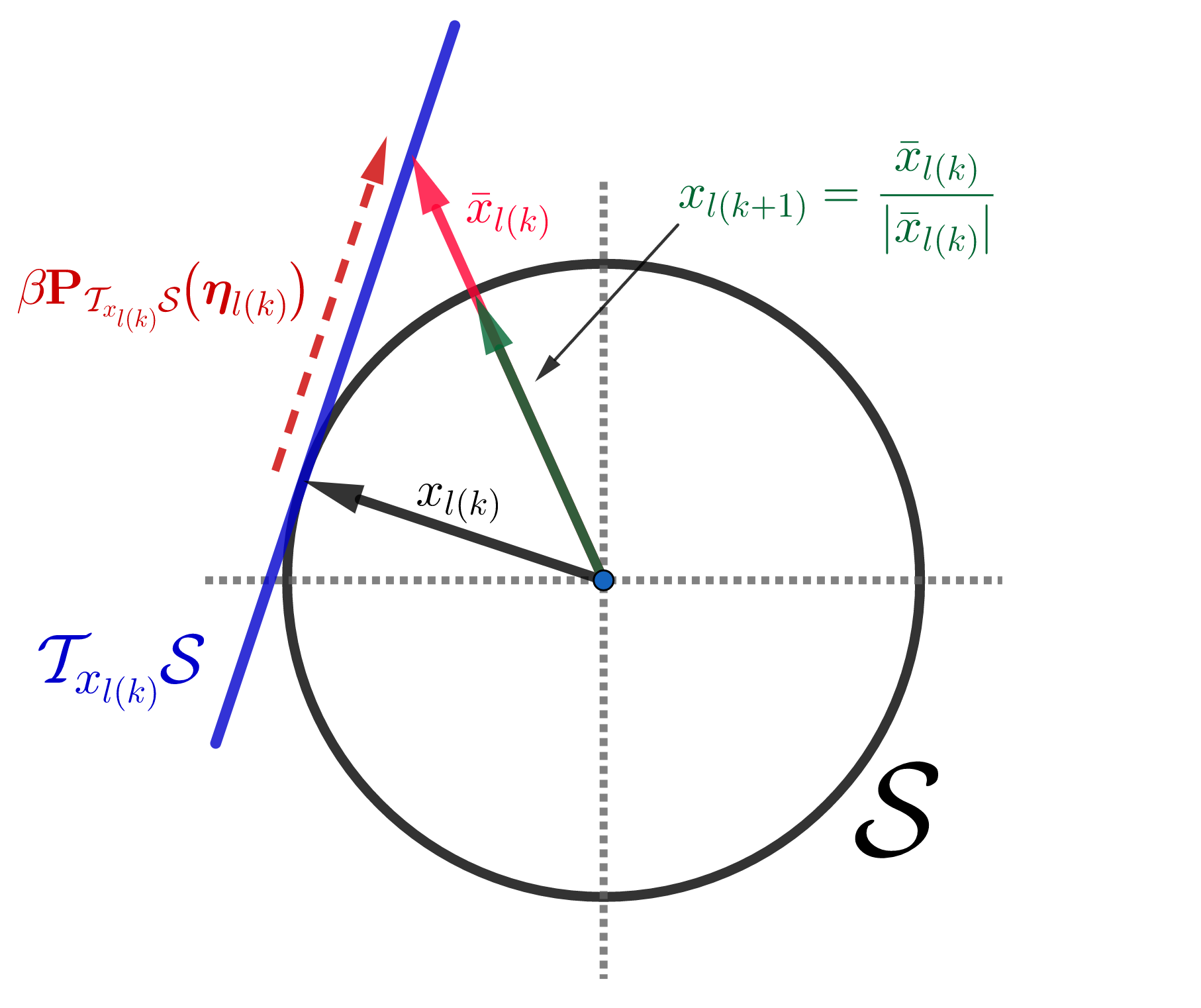
Note that 𝐱(k),𝐱(k+1)subscript𝐱𝑘subscript𝐱𝑘1\mathbf{x}_{(k)},\mathbf{x}_{(k+1)} are both on the complex circle manifold, i.e. CMC points, while 𝐱¯(k)subscript¯𝐱𝑘\bar{\mathbf{x}}_{(k)} is generally a non-CMC point with magnitude 1absent1\geq 1. The proposed algorithm from these steps is named as Projection-Descent-Retraction (PDR) and it is visually illustrated in Fig. 3.
Refer to caption
Figure 3: Illustration of the update xl(k+1)subscript𝑥𝑙𝑘1x_{l(k+1)} starting from xl(k)subscript𝑥𝑙𝑘x_{l(k)}, where xl(k)subscript𝑥𝑙𝑘x_{l(k)} is the l𝑙l-th element of the complex vector 𝐱(k)subscript𝐱𝑘{\mathbf{x}}_{(k)}.

PDR for beampattern design: The cost function of the beampattern design problem defined in (12) is a quadratic w.r.t. the complex variable 𝐱𝐱\mathbf{x} and its gradient is given by 𝐱f¯(𝐱)=2(𝐏+γ𝐈)𝐱2𝐪subscript𝐱¯𝑓𝐱2𝐏𝛾𝐈𝐱2𝐪\nabla_{\mathbf{x}}\bar{f}(\mathbf{x})=2({\mathbf{P}}+\gamma{\mathbf{I}}){\mathbf{x}}-2{\mathbf{q}}. The procedure of minimizing the cost function f¯(𝐱)¯𝑓𝐱\bar{f}(\mathbf{x}) using the PDR approach is formally described in Algorithm 1. The convergence of Algorithm 1 is studied in the following sub-section. Assuming that Algorithm 1 converges, the convergence of Algorithm 2 (which alternates between ϕspsubscriptitalic-ϕ𝑠𝑝\phi_{sp} and 𝐱𝐱\mathbf{x} and achieves practical beampattern design) is guaranteed and already established in past works [38, 39, 8, 11].

Algorithm 1 Projection-Descent-Retraction (PDR)
Inputs: The cost function f¯(𝐱)¯𝑓𝐱\bar{f}(\mathbf{x}), 𝐱(0)𝒮Lsubscript𝐱0superscript𝒮𝐿\mathbf{x}_{(0)}\in\mathcal{S}^{L}, a step size β𝛽\beta and a pre-defined threshold value ϵitalic-ϵ\epsilon.
Output: A solution 𝐱superscript𝐱\mathbf{x}^{\star} for optimizing f¯(𝐱)¯𝑓𝐱\bar{f}(\mathbf{x}) over the complex circle manifold 𝒮Lsuperscript𝒮𝐿\mathcal{S}^{L}.
(1) Set k=0𝑘0k=0.
(2) Evaluate the search direction: 𝜼(k)=𝐱f¯(𝐱(k))subscript𝜼𝑘subscript𝐱¯𝑓subscript𝐱𝑘\boldsymbol{\eta}_{(k)}=-\nabla_{\mathbf{x}}\bar{f}(\mathbf{x}_{(k)}) with computational complexity of 𝒪(L2)𝒪superscript𝐿2\mathcal{O}(L^{2}).
(3) Compute the projection of the 𝜼(k)subscript𝜼𝑘\boldsymbol{\eta}_{(k)} onto the tangent space according to Eq (19) as
𝐏𝒯𝐱(k)𝒮L(𝜼(k))=𝜼(k)Re{𝜼(k)𝐱(k)}𝐱(k)subscript𝐏subscript𝒯subscript𝐱𝑘superscript𝒮𝐿subscript𝜼𝑘subscript𝜼𝑘direct-productRedirect-productsuperscriptsubscript𝜼𝑘subscript𝐱𝑘subscript𝐱𝑘\mathbf{P}_{\mathcal{T}_{\mathbf{x}_{(k)}}\mathcal{S}^{L}}\big{(}\boldsymbol{\eta}_{(k)}\big{)}=\boldsymbol{\eta}_{(k)}-\text{Re}\{\boldsymbol{\eta}_{(k)}^{*}\odot\mathbf{x}_{(k)}\}\odot\mathbf{x}_{(k)} (21)
with computational complexity of 𝒪(L)𝒪𝐿\mathcal{O}(L).
(4) Compute the update of 𝐱(k)subscript𝐱𝑘\mathbf{x}_{(k)} on 𝒯𝐱(k)𝒮Lsubscript𝒯subscript𝐱𝑘superscript𝒮𝐿\mathcal{T}_{\mathbf{x}_{(k)}}\mathcal{S}^{L} as
𝐱¯(k)=𝐱(k)+β𝐏𝒯𝐱(k)𝒮L(𝜼(k))=𝐱(k)+β(𝜼(k)Re{𝜼(k)𝐱(k)}𝐱(k))subscript¯𝐱𝑘subscript𝐱𝑘𝛽subscript𝐏subscript𝒯subscript𝐱𝑘superscript𝒮𝐿subscript𝜼𝑘subscript𝐱𝑘𝛽subscript𝜼𝑘direct-productRedirect-productsubscriptsuperscript𝜼𝑘subscript𝐱𝑘subscript𝐱𝑘\begin{split}\bar{\mathbf{x}}_{(k)}&=\mathbf{x}_{(k)}+\beta\mathbf{P}_{\mathcal{T}_{\mathbf{x}_{(k)}}\mathcal{S}^{L}}\big{(}\boldsymbol{\eta}_{(k)}\big{)}\\ &=\mathbf{x}_{(k)}+\beta\big{(}\boldsymbol{\eta}_{(k)}-\text{Re}\{\boldsymbol{\eta}^{*}_{(k)}\odot\mathbf{x}_{(k)}\}\odot\mathbf{x}_{(k)}\Big{)}\end{split} (22)
(5) Compute the next iterate by retracting 𝐱¯(k)subscript¯𝐱𝑘\bar{\mathbf{x}}_{(k)} to the complex circle manifold by using the retraction formula Eq (20) as
𝐱(k+1)=𝐑(𝐱¯(k))subscript𝐱𝑘1𝐑subscript¯𝐱𝑘\mathbf{x}_{(k+1)}=\mathbf{R}\big{(}\bar{\mathbf{x}}_{(k)}\big{)} (23)
with computational complexity of 𝒪(L)𝒪𝐿\mathcal{O}(L).
if |f¯(𝐱(k+1))f¯(𝐱(k))|<ϵ¯𝑓subscript𝐱𝑘1¯𝑓subscript𝐱𝑘italic-ϵ|\bar{f}(\mathbf{x}_{(k+1)})-\bar{f}(\mathbf{x}_{(k)})|<\epsilon then
     STOP.
else
     k = k+1.
     GOTO step (3).
end if
Output: 𝐱Alg1=𝐱(k+1)subscriptsuperscript𝐱Alg1subscript𝐱𝑘1\mathbf{x}^{\star}_{\text{Alg\ref{Alg:PDR_basic}}}=\mathbf{x}_{(k+1)}

Computational complexity of PDR (Algorithm 1): As can be inferred from the step-wise description of Algorithm 1, there are two key steps of complexity 𝒪(L2)𝒪superscript𝐿2\mathcal{O}(L^{2}) and 𝒪(L)𝒪𝐿\mathcal{O}(L) respectively. For large L𝐿L, PDR’s complexity per iteration when optimizing quadratic cost functions is dominantly 𝒪(L2)𝒪superscript𝐿2\mathcal{O}(L^{2}), where L=NM𝐿𝑁𝑀L=NM. Table I shows computational complexity for the following state-of-the-art approaches along with PDR: Wideband Beampattern Formation via Iterative Techniques (WBFIT) [8], Semi-Definite relaxation with Randomization (SDR) [20, 21], Iterative Algorithm for Continuous Phase Case (IA-CPC) [33] and design algorithm based on Alternating Direction Method of Multipliers (ADMM) [34], where F𝐹F is the total number of iterations and T𝑇T denotes the number of randomization trails for SDR. From this table, it can be seen that PDR exhibits lower complexity compared to SDR and similar complexity to ADMM and IA-CPC (per iteration). The ADMM and IA-CPC approaches however need more iterations (larger F𝐹F) to achieve the same performance as PDR (as demonstrated in Section IV). Note that the complexity of competing methods is reported as derived in their respective/past work.

Table I: Computational complexity for the state of the art algorithms under the constant modulus constraint.
Method Complexity order
WBFIT[8] 𝒪(FNM2)𝒪𝐹𝑁superscript𝑀2\mathcal{O}(FNM^{2})
ADMM[34] 𝒪(FN2M2)𝒪𝐹superscript𝑁2superscript𝑀2\mathcal{O}(FN^{2}M^{2})
SDR[20, 21] 𝒪(N3.5M3.5)+𝒪(TN2M2)𝒪superscript𝑁3.5superscript𝑀3.5𝒪𝑇superscript𝑁2superscript𝑀2\mathcal{O}(N^{3.5}M^{3.5})+\mathcal{O}(TN^{2}M^{2})
IA-CPC [33] 𝒪(FN2M2)𝒪𝐹superscript𝑁2superscript𝑀2\mathcal{O}(FN^{2}M^{2})
PDR 𝒪(FN2M2)𝒪𝐹superscript𝑁2superscript𝑀2\mathcal{O}(FN^{2}M^{2})
Algorithm 2 Projection-Descent-Retraction (PDR) for the beampattern design problem
Inputs: dspsubscript𝑑𝑠𝑝d_{sp}, 𝐅psubscript𝐅𝑝\mathbf{F}_{p}, 𝐚spsubscript𝐚𝑠𝑝\mathbf{a}_{sp} for p=N2,,0,,N21𝑝𝑁20𝑁21p=-\frac{N}{2},...,0,...,\frac{N}{2}-1, s=1,2,..,Ss=1,2,..,S, 𝐱(0)𝒮Lsuperscript𝐱0superscript𝒮𝐿\mathbf{x}^{(0)}\in\mathcal{S}^{L}, a step size β𝛽\beta and pre-defined threshold values ϵitalic-ϵ\epsilon and ζ𝜁\zeta.
Output: A solution 𝐱superscript𝐱\mathbf{x}^{\star} for the problem in Eq (11).
(1) Compute 𝐏=p𝐅pH𝐀pH𝐀p𝐅p𝐏subscript𝑝subscriptsuperscript𝐅𝐻𝑝subscriptsuperscript𝐀𝐻𝑝subscript𝐀𝑝subscript𝐅𝑝\mathbf{P}=\sum_{p}\mathbf{F}^{H}_{p}\mathbf{A}^{H}_{p}\mathbf{A}_{p}\mathbf{F}_{p}
(2) Set m=1𝑚1m=1.
(3) Set ϕsp=arg(𝐚spH𝐅p𝐱(m1))sandpsubscriptitalic-ϕ𝑠𝑝argsubscriptsuperscript𝐚𝐻𝑠𝑝subscript𝐅𝑝superscript𝐱𝑚1for-all𝑠and𝑝\phi_{sp}=\text{arg}(\mathbf{a}^{H}_{sp}\mathbf{F}_{p}\mathbf{x}^{(m-1)})\ \forall\ s\ \text{and}\ p.
(4) Update 𝐝𝐝\mathbf{d}: 𝐝=[d1pejϕ1p,,dSpejϕSp]Tp𝐝superscriptsubscript𝑑1𝑝superscript𝑒𝑗subscriptitalic-ϕ1𝑝subscript𝑑𝑆𝑝superscript𝑒𝑗subscriptitalic-ϕ𝑆𝑝𝑇for-all𝑝\mathbf{d}=[d_{1p}e^{j\phi_{1p}},\ldots,d_{Sp}e^{j\phi_{Sp}}]^{T}\ \forall\ p.
(5) Update 𝐪𝐪\mathbf{q}: 𝐪=p𝐅pH𝐀pH𝐝p𝐪subscript𝑝subscriptsuperscript𝐅𝐻𝑝subscriptsuperscript𝐀𝐻𝑝subscript𝐝𝑝\mathbf{q}=\sum_{p}\mathbf{F}^{H}_{p}\mathbf{A}^{H}_{p}\mathbf{d}_{p}.
(6) Use Algorithm 1 with the following inputs: the cost function f¯(𝐱(k))¯𝑓subscript𝐱𝑘\bar{f}(\mathbf{x}_{(k)}) defined in Eq (11), 𝐱(0)=𝐱(m1)subscript𝐱0superscript𝐱𝑚1\mathbf{x}_{(0)}=\mathbf{x}^{(m-1)}, β𝛽\beta and ϵitalic-ϵ\epsilon.
(7) Set 𝐱(m)=xAlg1superscript𝐱𝑚subscriptsuperscript𝑥Alg1\mathbf{x}^{(m)}=x^{\star}_{\text{Alg\ref{Alg:PDR_basic}}}.
if 𝐱(m)𝐱(m1)<ζnormsuperscript𝐱𝑚superscript𝐱𝑚1𝜁\|\mathbf{x}^{(m)}-\mathbf{x}^{(m-1)}\|<\zeta then
     STOP.
else
     m = m+1
     GOTO step (3).
end if
Output: 𝐱=𝐱(m)superscript𝐱superscript𝐱𝑚\mathbf{x}^{\star}=\mathbf{x}^{(m)}

III-D Convergence Analysis

The update 𝐱¯(k)=𝐱(k)+β𝐏𝒯𝐱(k)𝒮L(𝜼(k))subscript¯𝐱𝑘subscript𝐱𝑘𝛽subscript𝐏subscript𝒯subscript𝐱𝑘superscript𝒮𝐿subscript𝜼𝑘\bar{\mathbf{x}}_{(k)}=\mathbf{x}_{(k)}+\beta\mathbf{P}_{\mathcal{T}_{\mathbf{x}_{(k)}}\mathcal{S}^{L}}\big{(}\boldsymbol{\eta}_{(k)}\big{)} in Step 4 of Algorithm 1 will produce a point on the tangent space 𝒯𝐱(k)𝒮Lsubscript𝒯subscript𝐱𝑘superscript𝒮𝐿\mathcal{T}_{\mathbf{x}_{(k)}}\mathcal{S}^{L} with a decrease in the cost if the step size β𝛽\beta is chosen carefully. A condition on the step size that ensures a decrease in the cost function is provided in the following lemma.

Lemma III.1

Let λ𝐏+γ𝐈subscript𝜆𝐏𝛾𝐈\lambda_{\mathbf{P}+\gamma\mathbf{I}} denote the largest eigenvalue of the matrix (𝐏+γ𝐈𝐏𝛾𝐈\mathbf{P}+\gamma\mathbf{I}). If the step size β𝛽\beta satisfies

0<β<1λ𝐏+γ𝐈0𝛽1subscript𝜆𝐏𝛾𝐈0<\beta<\frac{1}{\lambda_{\mathbf{P}+\gamma\mathbf{I}}} (24)

then f¯(𝐱(k))f¯(𝐱¯(k))¯𝑓subscript𝐱𝑘¯𝑓subscript¯𝐱𝑘\bar{f}(\mathbf{x}_{(k)})\geq\bar{f}(\bar{\mathbf{x}}_{(k)}).

Proof:

See subsection A-A of the Appendix. ∎

In the next lemma, we show that the cost function f¯(𝐱)¯𝑓𝐱\bar{f}(\mathbf{x}) is non-increasing through the retraction step given that the positive scalar γ𝛾\gamma satisfies a certain condition.

Lemma III.2

Let λ𝐏subscript𝜆𝐏\lambda_{\mathbf{P}} denote the largest eigenvalue of the matrix 𝐏𝐏\mathbf{P}. If

γL8λ𝐏+𝐪2𝛾𝐿8subscript𝜆𝐏subscriptnorm𝐪2\gamma\geq\frac{L}{8}\lambda_{\mathbf{P}}+\|\mathbf{q}\|_{2} (25)

then f¯(𝐱¯(k))f¯(𝐱(k+1))¯𝑓subscript¯𝐱𝑘¯𝑓subscript𝐱𝑘1\bar{f}(\bar{\mathbf{x}}_{(k)})\geq\bar{f}(\mathbf{x}_{(k+1)}).

Proof:

See subsection A-B of the Appendix. ∎

In the following lemma, we show that the original cost function f(𝐱)𝑓𝐱f(\mathbf{x}) defined in (11) is non-increasing and the iterative procedure converges.

Lemma III.3

Given γL8λ𝐏+𝐪2𝛾𝐿8subscript𝜆𝐏subscriptnorm𝐪2\gamma\geq\frac{L}{8}\lambda_{\mathbf{P}}+\|\mathbf{q}\|_{2} and 0<β<1/λ𝐏+γ𝐈0𝛽1subscript𝜆𝐏𝛾𝐈0<\beta<1/{\lambda_{\mathbf{P}+\gamma\mathbf{I}}} the sequence {f¯(𝐱(k))}k=0superscriptsubscript¯𝑓subscript𝐱𝑘𝑘0\{\bar{f}(\mathbf{x}_{(k)})\}_{k=0}^{\infty} generated by Algorithm 1 is non-increasing (from Lemmas III.1 and III.2) and hence the sequence {f(𝐱(k))}k=0superscriptsubscript𝑓subscript𝐱𝑘𝑘0\{f(\mathbf{x}_{(k)})\}_{k=0}^{\infty} is also non-increasing. Moreover, since f(𝐱)0𝑓𝐱0f(\mathbf{x})\geq 0 (sum of norms), 𝐱for-all𝐱\forall\ \mathbf{x} , it is bounded below and converges to a finite value fsuperscript𝑓f^{*}.

Proof:

See subsection A-C of the Appendix. ∎

Remark: The proposed PDR has essentially enabled a gradient based update while maintaining feasibility on the (non-convex) complex circle manifold with guarantees of monotonic cost function decrease and convergence. We note that the guarantees provided here may not necessarily generalize to other non-convex manifolds. It is indeed structure specific to this problem that enables our construction as shown in Fig. 3.

III-E Orthogonal waveform design across antennas

The feasible set of the optimization problem that incorporating CMC and orthogonality to design the beampattern can be understood as the intersection of the aforementioned complex circle manifold and the complex Stiefel manifold [36, 40, 41]. Working directly on the intersection of these manifolds is difficult (or impossible) because the intersection of two manifolds is not always a manifold, and even when it is, it may not be easy to describe. Our strategy to deal with this problem is to optimize over the complex circle manifold while modifying the beampattern design cost function with the addition of a penalty term that emphasizes orthogonality. Specifically, the cost function in (12) can be altered by adding the following penalty term α𝐗H𝐗N𝐈MF2,α>0𝛼subscriptsuperscriptnormsuperscript𝐗𝐻𝐗𝑁subscript𝐈𝑀2𝐹𝛼0\alpha\|\mathbf{X}^{H}\mathbf{X}-N\mathbf{I}_{M}\|^{2}_{F},\ \alpha>0, where 𝐗N×M𝐗superscript𝑁𝑀\mathbf{X}\in\mathbb{C}^{N\times M} is the transmit waveform matrix 𝐗=[𝐱0𝐱1𝐱M1]𝐗subscript𝐱0subscript𝐱1subscript𝐱𝑀1\mathbf{X}=[\mathbf{x}_{0}\quad\mathbf{x}_{1}\quad...\quad\mathbf{x}_{M-1}] and related to the vector 𝐱𝐱\mathbf{x} defined in Eq (6) through the vectorization operator, i.e., 𝐱=vec(𝐗)𝐱vec𝐗\mathbf{x}=\text{vec}(\mathbf{X}). This way, 𝐗𝐗\mathbf{X} will be “encouraged” to be orthogonal/unitary, and with this penalty term, the optimization problem that assimilates both constraints can be written as

min𝐱Lh(𝐱)=𝐱H𝐏𝐱𝐪H𝐱𝐱H𝐪+r+α𝐗H𝐗N𝐈MF2s.t.: |𝐱|=𝟏subscript𝐱superscript𝐿𝐱superscript𝐱𝐻𝐏𝐱superscript𝐪𝐻𝐱superscript𝐱𝐻𝐪𝑟𝛼subscriptsuperscriptdelimited-∥∥superscript𝐗𝐻𝐗𝑁subscript𝐈𝑀2𝐹s.t.: 𝐱1\begin{array}[]{cc}\displaystyle\min_{\mathbf{x}\in\mathbb{C}^{L}}&\begin{split}h(\mathbf{x})=&\mathbf{x}^{H}\mathbf{P}\mathbf{x}-\mathbf{q}^{H}\mathbf{x}-\mathbf{x}^{H}\mathbf{q}+r\\ &+\alpha\|\mathbf{X}^{H}\mathbf{X}-N\mathbf{I}_{M}\|^{2}_{F}\end{split}\\ \text{s.t.: }&|\mathbf{x}|=\mathbf{1}\\ \end{array} (26)

The gradient of the cost function h(𝐱)𝐱h(\mathbf{x}) w.r.t. 𝐱𝐱\mathbf{x} can be computed by utilizing the relation between the variables 𝐱𝐱\mathbf{x} and 𝐗𝐗\mathbf{X}. The penalty term is a scalar function of the matrix 𝐗𝐗\mathbf{X}, and the gradient of a scalar function with respect to 𝐗𝐗\mathbf{X} and 𝐱𝐱\mathbf{x} can be also related through the vec operator [42], i.e.,

𝐱(𝐗H𝐗N𝐈MF2)=vec(𝐗(𝐗H𝐗N𝐈MF2))subscript𝐱subscriptsuperscriptdelimited-∥∥superscript𝐗𝐻𝐗𝑁subscript𝐈𝑀2𝐹vecsubscript𝐗subscriptsuperscriptdelimited-∥∥superscript𝐗𝐻𝐗𝑁subscript𝐈𝑀2𝐹\begin{split}\nabla_{\mathbf{x}}\big{(}\|\mathbf{X}^{H}\mathbf{X}-N\mathbf{I}_{M}\|^{2}_{F}\big{)}=\text{vec}\Big{(}\nabla_{\mathbf{X}}\big{(}\|\mathbf{X}^{H}\mathbf{X}-N\mathbf{I}_{M}\|^{2}_{F}\big{)}\Big{)}\end{split}

using this relation, the gradient of the penalty term w.r.t. 𝐱𝐱\mathbf{x} is given by

𝐱(𝐗H𝐗N𝐈MF2)=vec(𝐗(𝐗H𝐗N𝐈MF2))=4vec(𝐗𝐗H𝐗)subscript𝐱subscriptsuperscriptdelimited-∥∥superscript𝐗𝐻𝐗𝑁subscript𝐈𝑀2𝐹vecsubscript𝐗subscriptsuperscriptdelimited-∥∥superscript𝐗𝐻𝐗𝑁subscript𝐈𝑀2𝐹4vecsuperscript𝐗𝐗𝐻𝐗\begin{split}\nabla_{\mathbf{x}}\big{(}\|\mathbf{X}^{H}\mathbf{X}-N\mathbf{I}_{M}\|^{2}_{F}\big{)}&=\text{vec}\Big{(}\nabla_{\mathbf{X}}\big{(}\|\mathbf{X}^{H}\mathbf{X}-N\mathbf{I}_{M}\|^{2}_{F}\big{)}\Big{)}\\ &=4\ \text{vec}(\mathbf{X}\mathbf{X}^{H}\mathbf{X})\end{split}

and hence the gradient of the cost function h(𝐱)𝐱h(\mathbf{x}) is given by

𝐱h(𝐱)=2(𝐏+γ𝐈)𝐱2𝐪+4αvec(𝐗𝐗H𝐗)subscript𝐱𝐱2𝐏𝛾𝐈𝐱2𝐪4𝛼vecsuperscript𝐗𝐗𝐻𝐗\begin{split}\nabla_{\mathbf{x}}h(\mathbf{x})=2({\mathbf{P}}+\gamma{\mathbf{I}}){\mathbf{x}}-2{\mathbf{q}}+4\alpha\text{vec}(\mathbf{X}\mathbf{X}^{H}\mathbf{X})\end{split} (27)

The optimization problem in (26) can now be solved by executing Algorithm 1 but with a different cost function, i.e. h(𝐱)𝐱h(\mathbf{x}). As before, practical beampattern design in the presence of CMC while encouraging orthogonality can be obtained by Algorithm 2, which invokes Algorithm 1 in Step 6.

Refer to caption
(a) Unconstrainted
Refer to caption
(b) WBFIT[8]
Refer to caption
(c) SDR[20, 21]
Refer to caption
(d) IA-CPC [33]
Refer to caption
(e) ADMM[34]
Refer to caption
(f) PDR
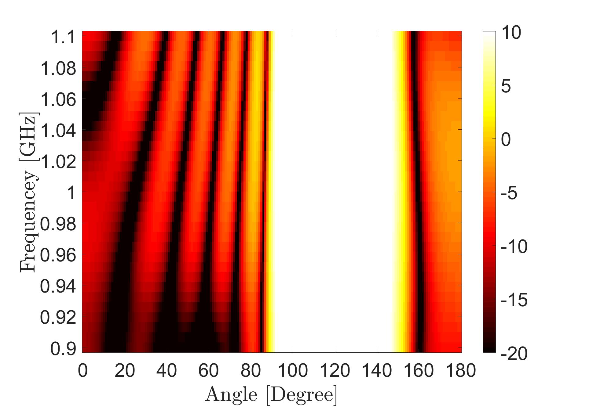
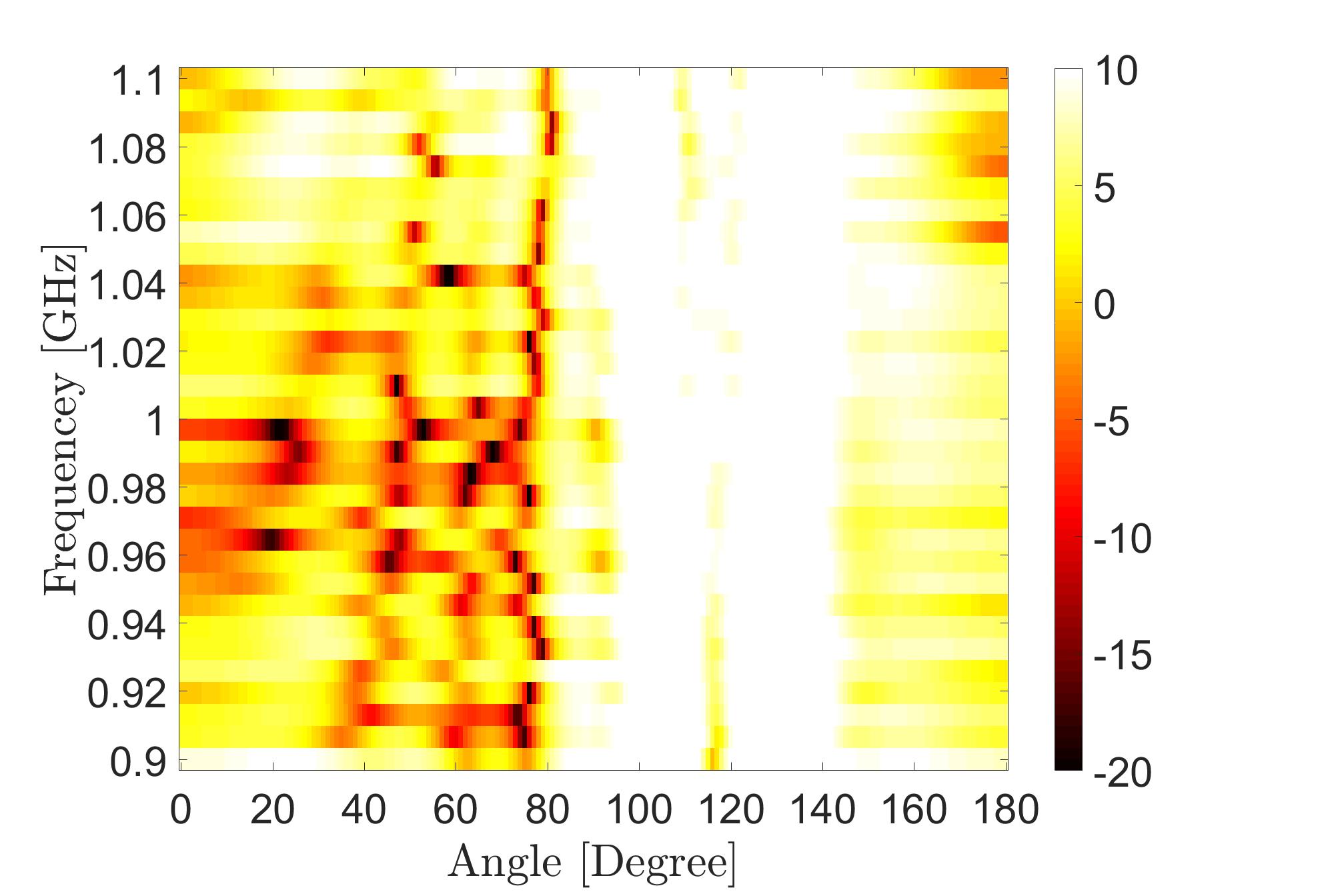
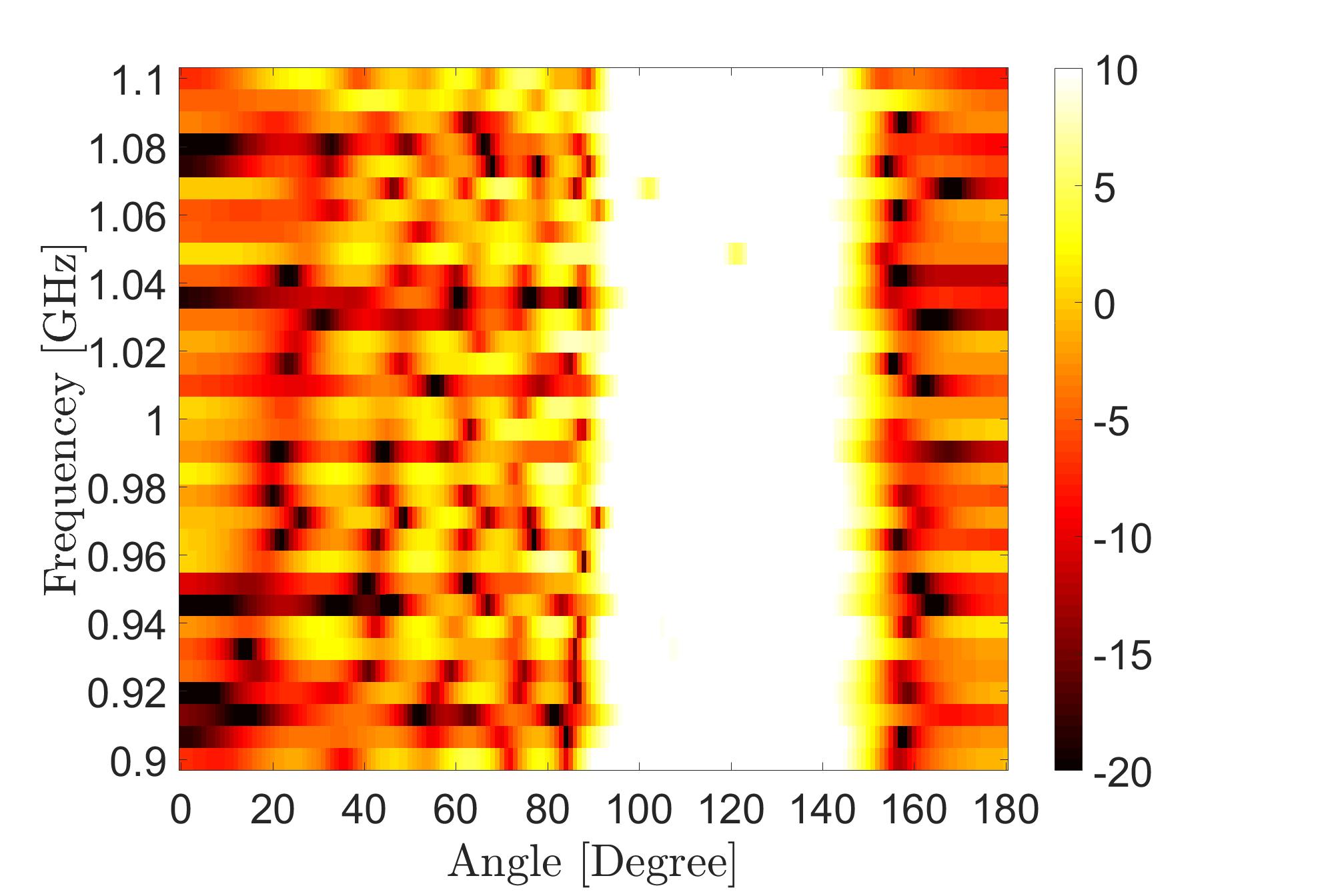
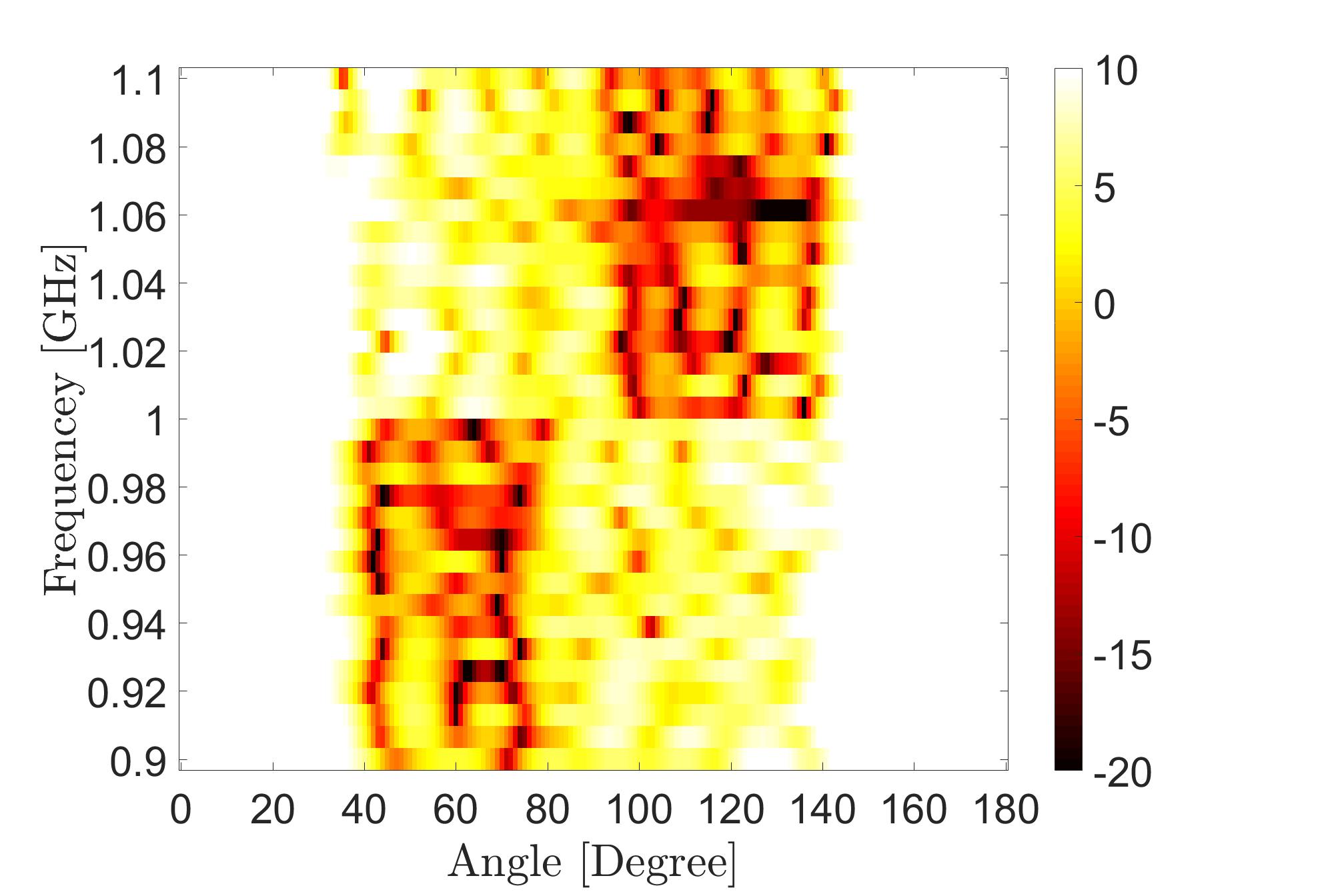
Figure 4: The beampattern for Case 1 obtained by (a) the unconstrained design, (b) WBFIT, (c) SDR, (d) IA-CPC, (e) ADMM, and (f) PDR.

IV Numerical Results

Various numerical simulations are provided to assess the performance of PDR based beampattern design and compare it to state-of-the-art approaches. Results from the following three simulations are reported next: 1) beampattern design under the constant modulus constraint, 2) beampattern design under both constant modulus and orthogonality constraints, and 3) an investigation to examine the robustness of the produced waveforms under the two constraints to direction mismatch.

Unless otherwise specified, the following settings are used in this section. Consistent with past work [8, 11], we assume a ULA MIMO radar system with the following parameters: the number of transmit antennas M=10𝑀10M=10, the number of time samples N=32𝑁32N=32, carrier frequency fc=1subscript𝑓𝑐1f_{c}=1 GHz, bandwidth B=200𝐵200B=200 MHz, sampling rate Ts=1/Bsubscript𝑇𝑠1𝐵T_{s}=1/B, inter-element spacing d=c/2(fc+B/2)𝑑𝑐2subscript𝑓𝑐𝐵2d=c/2(f_{c}+B/2), and the spatial angle θ𝜃\theta is divided into S=180𝑆180S=180 points.

IV-A Beampattern design under CMC

We examine the beampattern design problem under CMC and compare the performance of PDR to the following state-of-the-art approaches: 1) Wideband Beampattern Formation via Iterative Techniques (WBFIT) [8], 2) Semi-Definite relaxation with Randomization (SDR) [20, 21], 3) Iterative Algorithm for Continuous Phase Case (IA-CPC) [33], and 4) Design algorithm based on Alternating Direction Method of Multipliers (ADMM) [34]. Similar to our work, SDR and IA-CPC are devised as approaches that optimize quadratic cost functions while enforcing CMC. That is, IA-CPC and SDR will be applied to optimize the same cost function that PDR also addresses. Finally, we also report results for the case where no constraints are posed on the waveform code 𝐱𝐱\mathbf{x}. This unconstrained design is impractical but provides a bound on the performance of all constrained methods. For a fair comparison, PDR and the competing methods are initialized with the same waveform; a pseudo-random vector of unit magnitude complex entries.

We consider three distinct specifications of the desired beampattern. Case 1 (based on [8]) only has angular dependence and has been specified to uniformly illuminate a broadside region. Case 2 (based on [11]) has both angle and frequency dependence. Case 3 has more specifications such as restricting the transmission to be in a certain frequency band for spectrally crowded scenarios [43, 44]. The step size for PDR was chosen as β=0.00005𝛽0.00005\beta=0.00005, β=0.00004𝛽0.00004\beta=0.00004, and β=0.00004𝛽0.00004\beta=0.00004 for Case 1, Case 2, and Case 3, respectively. The parameters for all competing methods were set as prescribed in their respective papers or by using code given directly by the authors.

Case 1: The desired beampattern is given by

d(θ,f)={1θ=[95,145]0Otherwise.𝑑𝜃𝑓cases1𝜃superscript95superscript1450Otherwised(\theta,f)=\begin{cases}1&\theta=[95^{\circ},145^{\circ}]\\ 0&\text{Otherwise}.\end{cases} (28)
Table II: The deviation from the desired beampattern (the cost function in Eq (7)) for Case 1.
Method 10log10(ρ(𝐱))10subscriptlog10𝜌𝐱10\ \text{log}_{10}(\rho(\mathbf{x})) Run time (sec) Iterations
Unconstrained 19.9319.9319.93 - -
WBFIT[8] 31.9331.9331.93 0.370.370.37 135135135
SDR[20, 21] 25.5025.5025.50 110711071107 313131
IA-CPC [33] 28.3028.3028.30 14.3914.3914.39 172172172
ADMM[34] 24.9324.9324.93 19.2019.2019.20 200200200
PDR 22.8022.80\mathbf{22.80} 9.279.27\mathbf{9.27} 121121121

In Table II, the values of the deviation from the desired beampattern ρ(𝐱)𝜌𝐱\rho(\mathbf{x}) (where ρ(𝐱)𝜌𝐱\rho(\mathbf{x}) is the cost function in Eq (7)) are reported. Table II confirms that PDR provides substantial gains, about 2.13 dB, 2.7 dB, and 5.5 dB over ADMM, SDR, and IA-CPC, respectively.

In Fig. 4 a 2D visualization of the designed beampattern is shown for each of the competing methods. Clearly, PDR achieves a beampattern that is closest to the unconstrained case, which naturally serves as a bound on the performance.

Case 2: The desired beampattern is given by

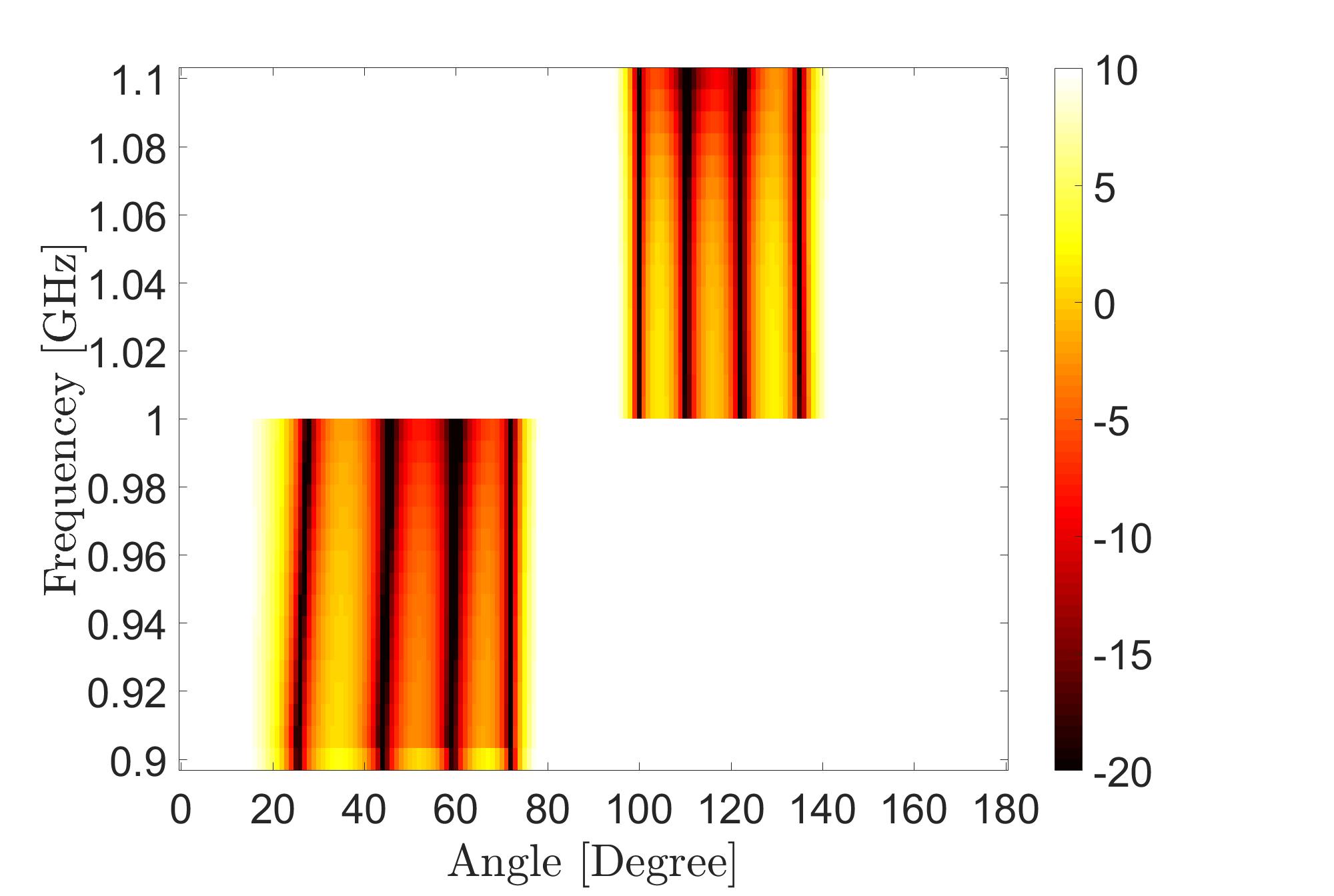
d(θ,f)={0θ=[10,80],B2+fcffc0θ=[95,145],fcfB2+fc1Otherwise.𝑑𝜃𝑓cases0formulae-sequence𝜃superscript10superscript80𝐵2subscript𝑓𝑐𝑓subscript𝑓𝑐0formulae-sequence𝜃superscript95superscript145subscript𝑓𝑐𝑓𝐵2subscript𝑓𝑐1Otherwised(\theta,f)=\begin{cases}0&\theta=[10^{\circ},80^{\circ}],\ -\frac{B}{2}+f_{c}\leq f\leq f_{c}\\ 0&\theta=[95^{\circ},145^{\circ}],\ f_{c}\leq f\leq\frac{B}{2}+f_{c}\\ 1&\text{Otherwise}.\end{cases} (29)
Table III: The deviation from the desired beampattern (the cost function in Eq (7)) for Case 2.
Method 10log10(ρ(𝐱))10subscriptlog10𝜌𝐱10\ \text{log}_{10}(\rho(\mathbf{x})) Run time (sec) Iterations
Unconstrained 19.5219.5219.52 - -
WBFIT[8] 33.1133.1133.11 0.390.390.39 199199199
SDR[20, 21] 28.4128.4128.41 119011901190 333333
IA-CPC [33] 30.8630.8630.86 14.4714.4714.47 180180180
ADMM[34] 28.9128.9128.91 20.3620.3620.36 208208208
PDR 26.6926.69\mathbf{26.69} 7.387.38\mathbf{7.38} 115115115
Refer to caption
(a) Unconstrainted
Refer to caption
(b) WBFIT[8]
Refer to caption
(c) SDR[20, 21]
Refer to caption
(d) IA-CPC [33]
Refer to caption
(e) ADMM[34]
Refer to caption
(f) PDR
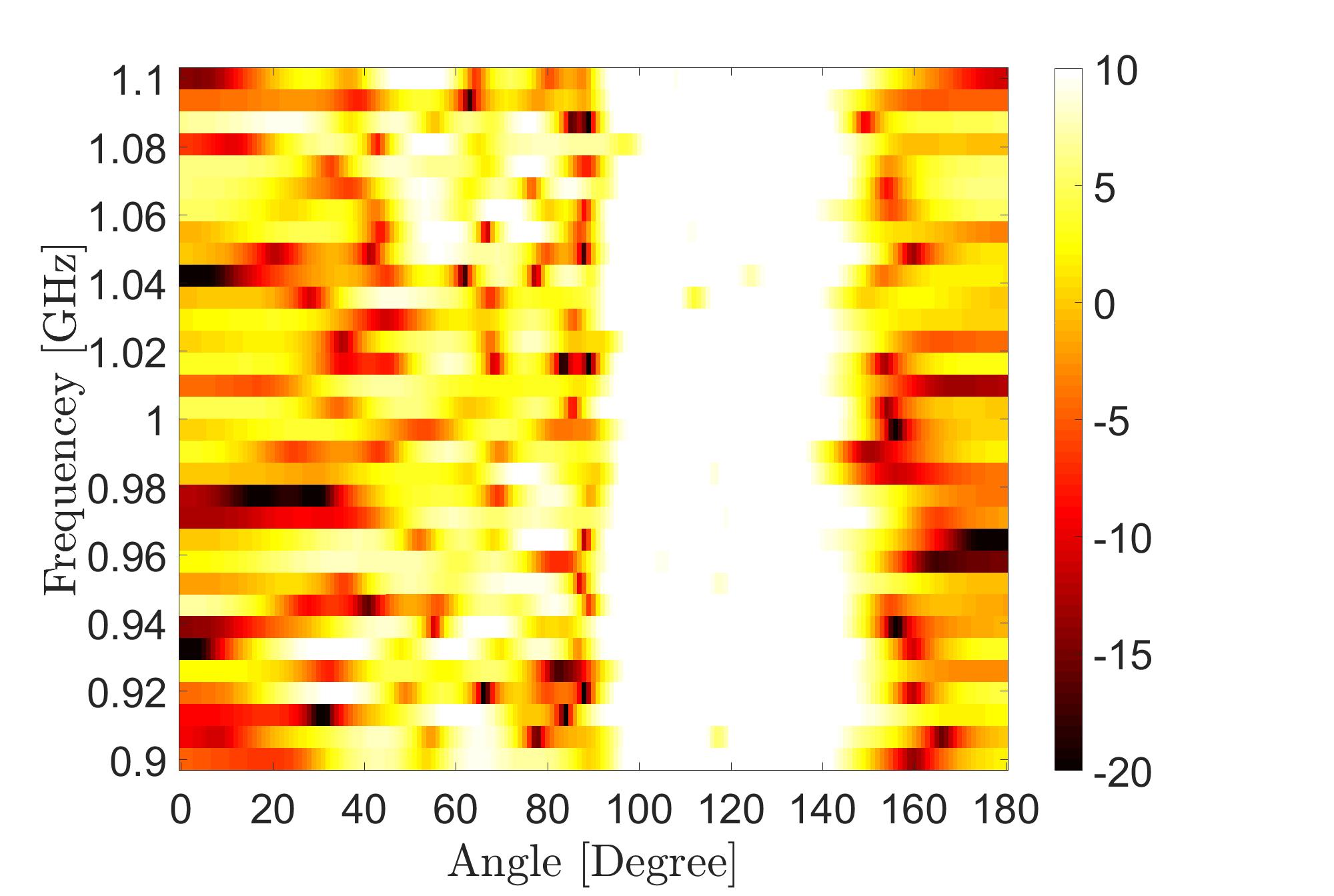
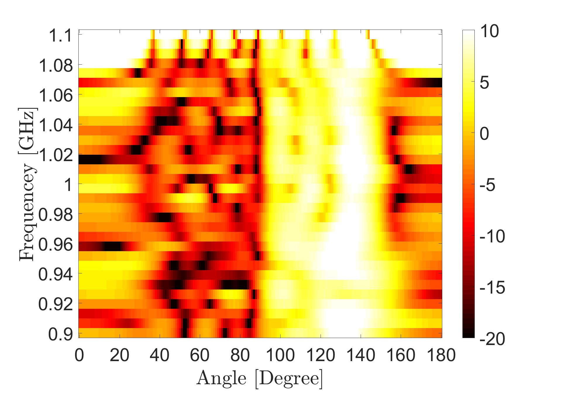
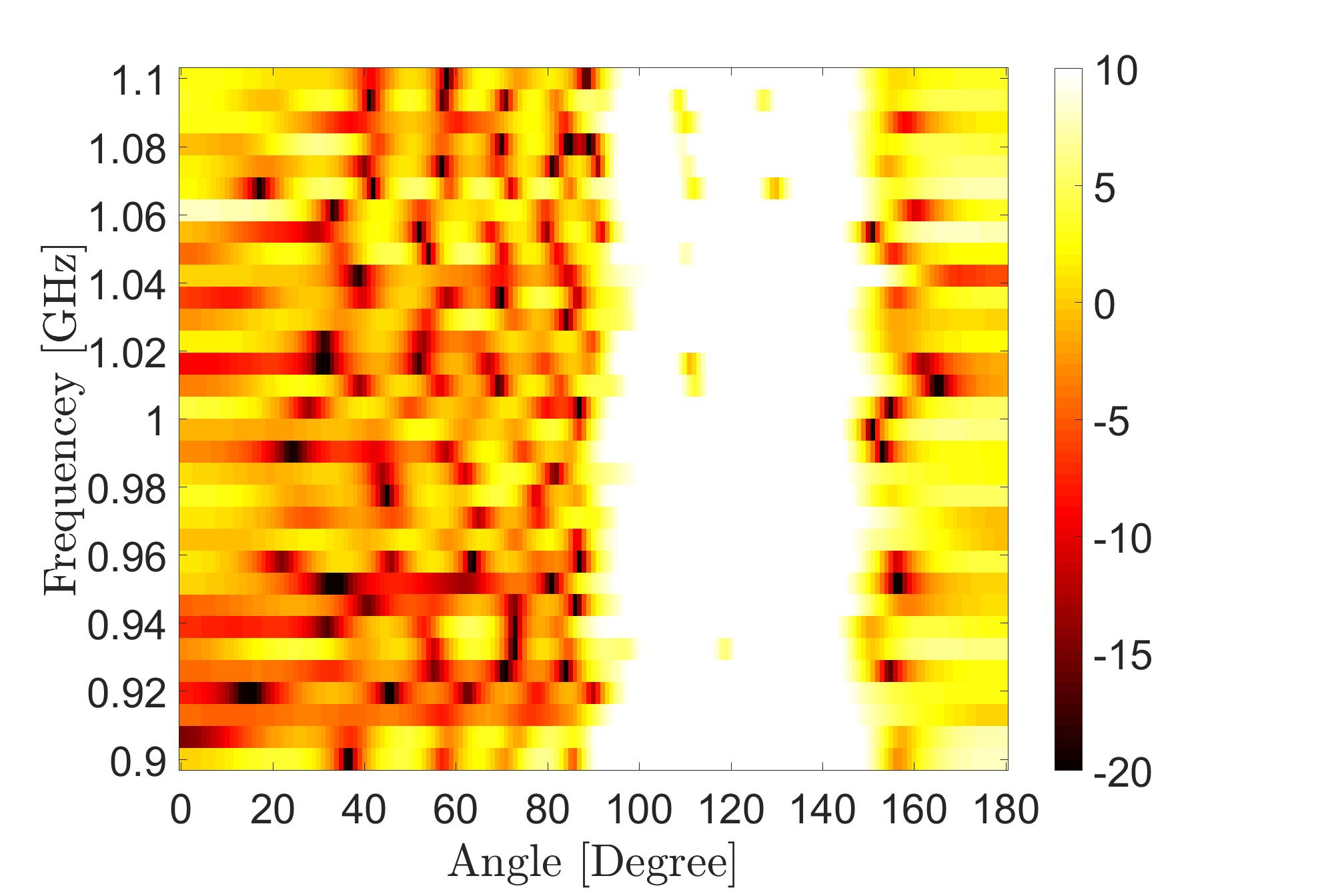
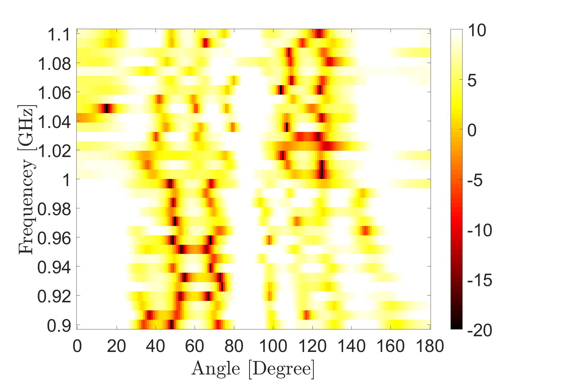
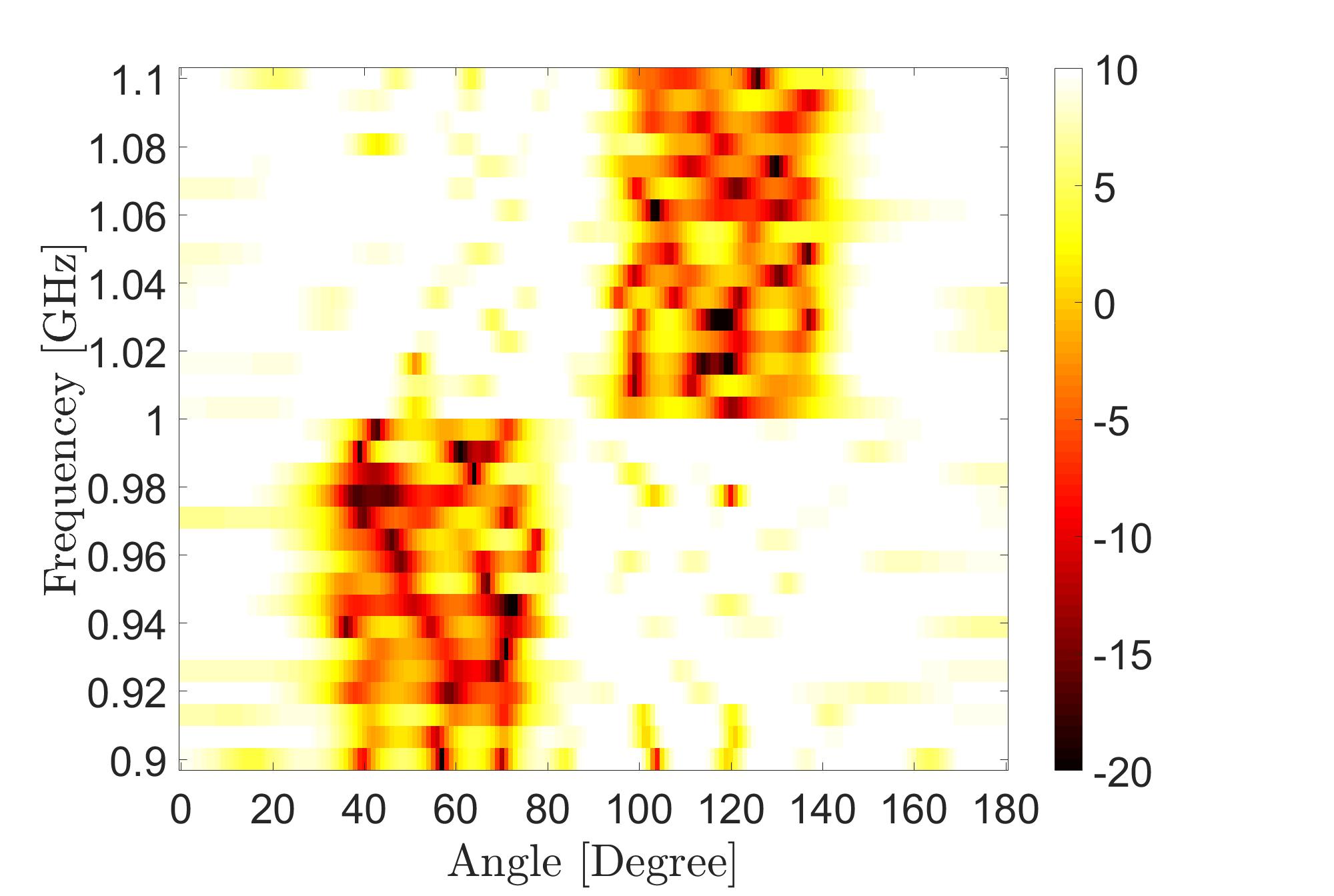
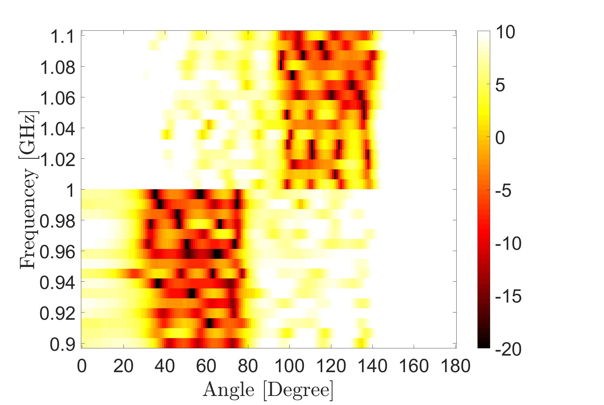
Figure 5: The beampattern for Case 2 obtained by (a) the unconstrained design, (b) WBFIT, (c) SDR, (d) IA-CPC, (e) ADMM, and (f) PDR.

Similar to Case 1, the values of the deviation from the desired beampattern are listed in Table III. Clearly, the PDR algorithm gives the closest value to the unconstrained case with a gap of 2 dB over the second best method. In Fig. 5, the designed beampattern is visualized for all the competing methods. Clearly, the beampattern that results from PDR is closer to the desired one than those resulting form competing methods.

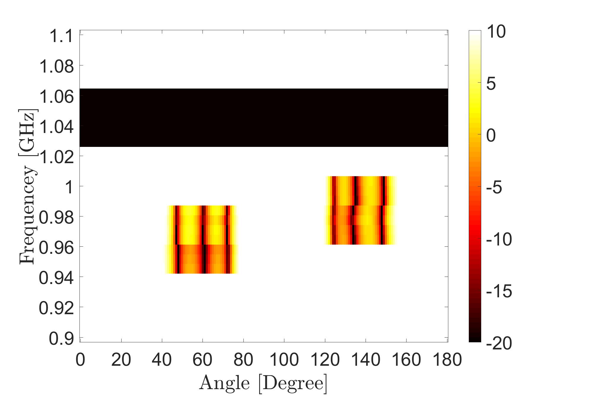
Case 3: For this scenario, the beampattern will be suppressed in two angular-frequency regions as follows

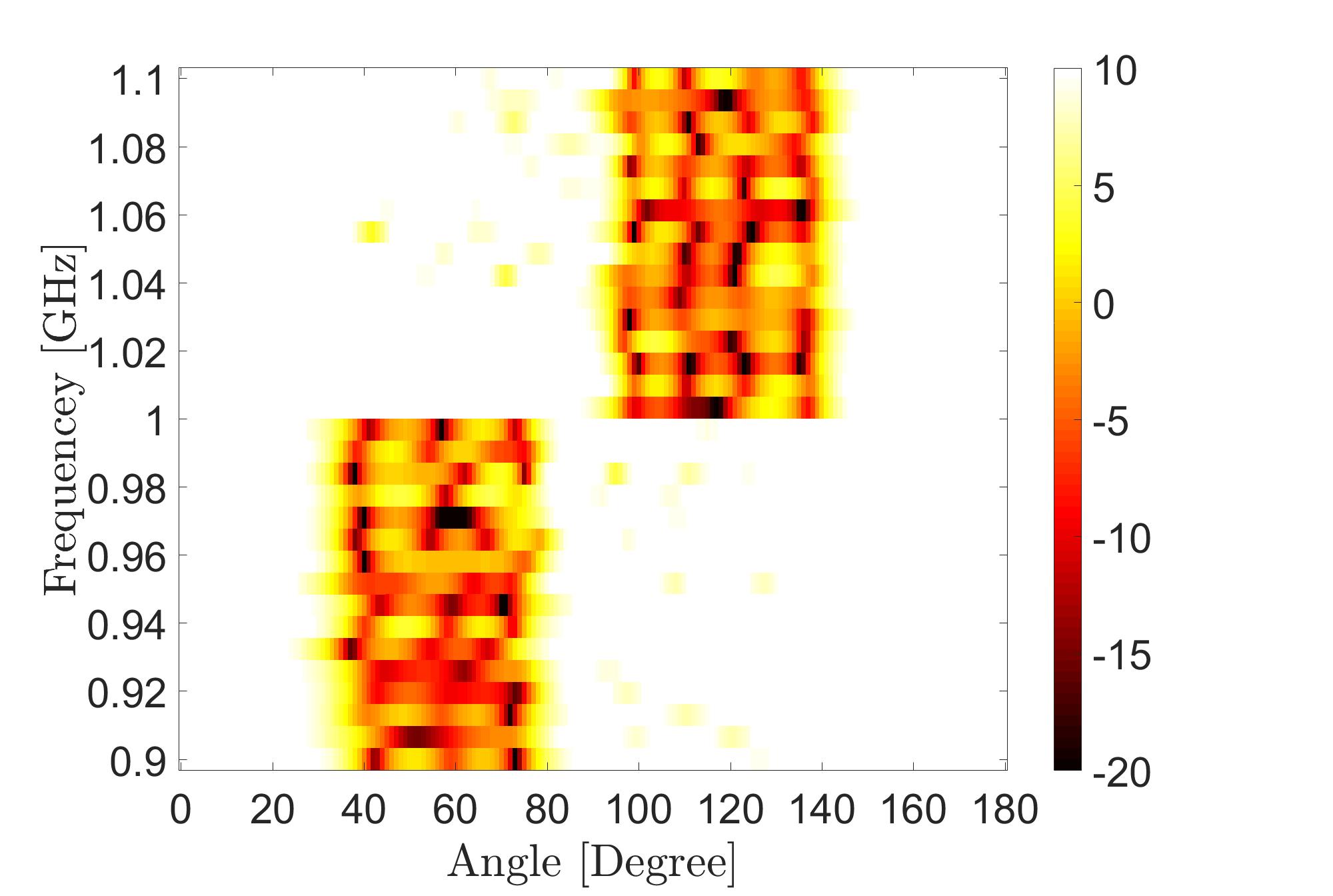
d(θ,f)={0θ=[40,80],f=[943.75,981.25]0θ=[120,160],f=[962.5,1000]1Otherwise.𝑑𝜃𝑓cases0formulae-sequence𝜃superscript40superscript80𝑓943.75981.250formulae-sequence𝜃superscript120superscript160𝑓962.510001Otherwised(\theta,f)=\begin{cases}0&\theta=[40^{\circ},80^{\circ}],\ f=[943.75,981.25]\\ 0&\theta=[120^{\circ},160^{\circ}],\ f=[962.5,1000]\\ 1&\text{Otherwise}.\end{cases} (30)

The transmission is restricted in certain practical frequency bands in accordance with [43, 44]. Precisely, these frequencies are: f=[1.025GHz,1.0625GHz]𝑓1.025GHz1.0625GHz\ f=[1.025\ \text{GHz},1.0625\ \text{GHz}] (see Fig. 6).

Refer to caption
Figure 6: The desired beampattern (Case 3).
Table IV: The deviation from the desired beampattern (the cost function in Eq (7)) for Case 3.
Method 10log10(ρ(𝐱))10subscriptlog10𝜌𝐱10\ \text{log}_{10}(\rho(\mathbf{x})) Run time (sec) Iterations
Unconstrained 18.1818.1818.18 - -
WBFIT[8] 34.2934.2934.29 1.551.551.55 102102102
SDR[20, 21] 28.2128.2128.21 126212621262 373737
IA-CPC [33] 31.7831.7831.78 18.5818.5818.58 192192192
ADMM[34] 28.2628.2628.26 24.1024.1024.10 231231231
PDR 27.8627.86\mathbf{27.86} 12.1412.14\mathbf{12.14} 142142142

As Table IV reveals, also in this case, PDR outperforms all competing methods in terms of deviation from the desired beampattern.

Remark: Note that Tables II, III, and IV also report run time (in seconds) as the time taken to optimize the waveform code 𝐱𝐱\mathbf{x}. For fairness of comparison, we used the same platform for all implementations: MATLAB R16, CPU Core i5, 3.1 GHz and 8 GB of RAM. Overall, Tables II, III, and IV show that the different methods exhibit complementary merits. WBFIT, one of the earliest methods proposed to solve this problem is the fastest, but its deviation from the idealized beampattern is highest. With more sophisticated optimization techniques, IA-CPC and SDR offer performance gains but also increase complexity. It is readily apparent from these tables that PDR is highly efficient computationally bettered only by WBFIT. And PDR offers nearly 7 dB of gain in performance over WBFIT. Hence the results corroborate our assertion that PDR provides the most favorable complexity-performance trade-off.

IV-B Joint CMC and orthogonality constraints

In this numerical simulation, the beampattern design under the CMC and orthogonality constraints using PDR (run with a step size β=0.00003𝛽0.00003\beta=0.00003) will be examined. The level of orthogonality will be measured by using the following quantity:

ISL0=20log10𝐗H𝐗N𝐈MFMN2subscriptISL020subscriptlog10subscriptnormsuperscript𝐗𝐻𝐗𝑁subscript𝐈𝑀𝐹𝑀superscript𝑁2\text{ISL}_{0}=20\ \text{log}_{10}\frac{\|\mathbf{X}^{H}\mathbf{X}-N\mathbf{I}_{M}\|_{F}}{\sqrt{MN^{2}}} (31)

where ISL is the Integrated Sidelobe Level between the transmitted signal defined in [27]. Orthogonality across antennas is equivalent to the auto correlation case (ISL at time-lag 00), i.e., ISL0subscriptISL0\text{ISL}_{0}. In terms of the desired beampattern, we consider the same scenario as Case 1 in the previous subsection. The values of the deviation from the desired beampattern are reported in Table V. PDR is now compared against approaches that also directly or approximately capture both CMC and orthogonality; this includes: 1) the well-known and widely used linear frequency modulated (LFM ) waveform code [45, 46], 2) Weighted-cyclic algorithm-new (WeCAN) [27], and 3) the recent simulated annealing based approach (SimulAnneal) [31], which is one of the few known techniques that performs explicit beampattern design under both CMC and orthogonality constraints.

First, compared to Table II, the deviation as reported in Table V is higher. This is of course to be expected because we are not just enforcing CMC, but also orthogonality which means a smaller feasible set of waveform codes to optimize over. The results in Table V reveal that LFM and WeCAN lead to somewhat high deviation - this is unsurprising since neither approach explicitly designs the beampattern. When α=100𝛼100\alpha=100, PDR leads to waveform codes that are orthogonal for all practical purposes as evidenced by the ISL measure. As Table V reveals, PDR achieves the closest beampattern to the desired one (lowest deviation in dB) with SimulAnneal as the second best. Remarkably, even with α=200𝛼200\alpha=200, i.e. when the emphasis on orthogonality is particularly strong (ISL of 12.1212.12-12.12 dB for PDR vs. 3.673.67-3.67 for SimulAnneal), PDR provides a gain of 1 dB. The gain of PDR over SimulAnneal is about 3 dB for comparable ISL values.

Table V: Cost function and Auto-correlation level for PDR vs WeCAN and SA-Method
Method 10log10(ρ(𝐱))10subscriptlog10𝜌𝐱10\ \text{log}_{10}(\rho(\mathbf{x})) α𝛼\alpha ISL0subscriptISL0\text{ISL}_{0} (dB) Time (sec)
LFM 32.9332.9332.93 - 302.53302.53-302.53 -
WeCAN [27] 32.7132.7132.71 - 102.92102.92-102.92 11.5211.5211.52
SimulAnneal [31] 30.7230.7230.72 - 3.673.67-3.67 9.299.299.29
PDR 27.7727.7727.77 808080 5.275.27-5.27 10.5810.5810.58
28.6428.6428.64 100100100 6.926.92-6.92 12.6712.6712.67
29.6629.6629.66 200200200 12.1212.12-12.12 15.0515.0515.05

IV-C Benefits of orthogonality: robustness to direction mismatch

The transmit-receive pattern GTR(θ,θ0)subscript𝐺𝑇𝑅𝜃subscript𝜃0G_{TR}(\theta,\theta_{0}) measures the beamformer response when the beam is digitally steered in the direction θ𝜃\theta and when the true location of the target is at angle θ0subscript𝜃0\theta_{0}. It has been shown in [23] and [14] (as an advantage of orthogonal over coherent signals) that for orthogonal signalling, the effect of the direction mismatch (when the target is not located in the center of the transmit beam) is minimal.

The pattern GTR(θ,θ0)subscript𝐺𝑇𝑅𝜃subscript𝜃0G_{TR}(\theta,\theta_{0}) can be expressed as

GTR(θ,θ0)=N|𝐚RH(θ)𝐚R(θ0)|2MR.|𝐚TH(θ)𝐑sT𝐚T(θ0)|2𝐚TH(θ)𝐑sT𝐚T(θ)formulae-sequencesubscript𝐺𝑇𝑅𝜃subscript𝜃0𝑁superscriptsuperscriptsubscript𝐚𝑅𝐻𝜃subscript𝐚𝑅subscript𝜃02subscript𝑀𝑅superscriptsuperscriptsubscript𝐚𝑇𝐻𝜃superscriptsubscript𝐑𝑠𝑇subscript𝐚𝑇subscript𝜃02superscriptsubscript𝐚𝑇𝐻𝜃superscriptsubscript𝐑𝑠𝑇subscript𝐚𝑇𝜃\displaystyle G_{TR}(\theta,\theta_{0})=N\frac{|\mathbf{a}_{R}^{H}(\theta)\mathbf{a}_{R}(\theta_{0})|^{2}}{M_{R}}.\frac{|\mathbf{a}_{T}^{H}(\theta)\mathbf{R}_{s}^{T}\mathbf{a}_{T}(\theta_{0})|^{2}}{\mathbf{a}_{T}^{H}(\theta)\mathbf{R}_{s}^{T}\mathbf{a}_{T}(\theta)} (32)

where MRsubscript𝑀𝑅M_{R} is the number of receiver antennas, 𝐚T(θ)subscript𝐚𝑇𝜃\mathbf{a}_{T}(\theta) and 𝐚R(θ)subscript𝐚𝑅𝜃\mathbf{a}_{R}(\theta) are the steering vectors on the transmitter and receiver sides, respectively. These steering vectors are defined in Equations (4.6) and (4.7) in [14]. 𝐑ssubscript𝐑𝑠\mathbf{R}_{s} is the transmit signal correlation matrix defined as

𝐑s=(𝐗T𝐚T(θ0))(𝐗T𝐚T(θ0))Hsubscript𝐑𝑠direct-productsuperscript𝐗𝑇subscript𝐚𝑇subscript𝜃0superscriptdirect-productsuperscript𝐗𝑇subscript𝐚𝑇subscript𝜃0𝐻\mathbf{R}_{s}=\big{(}\mathbf{X}^{T}\odot\mathbf{a}_{T}(\theta_{0})\big{)}\big{(}\mathbf{X}^{T}\odot\mathbf{a}_{T}(\theta_{0})\big{)}^{H} (33)

where 𝐗N×M𝐗superscript𝑁𝑀\mathbf{X}\in\mathbb{C}^{N\times M} is the transmit waveform matrix defined in Section III-E. For the two extreme cases 1) coherent transmission444In coherent transmission, the transmit signals from all antennas are phase-shifted versions from one reference signal [14]. (𝐑s=𝟙Msubscript𝐑𝑠subscript1𝑀\mathbf{R}_{s}={\mathbbm{1}_{M}}) and 2) orthogonal transmission (𝐑s=𝐈Msubscript𝐑𝑠subscript𝐈𝑀\mathbf{R}_{s}=\mathbf{I}_{M} ) [23], the transmit-receive patterns for these cases will be

GTR(coherent)(θ,θ0)=N|𝐚RH(θ)𝐚R(θ0)|2|𝐚TH(θ0)𝟏|2MRsubscript𝐺𝑇𝑅coherent𝜃subscript𝜃0𝑁superscriptsuperscriptsubscript𝐚𝑅𝐻𝜃subscript𝐚𝑅subscript𝜃02superscriptsuperscriptsubscript𝐚𝑇𝐻subscript𝜃012subscript𝑀𝑅\displaystyle G_{TR(\text{coherent})}(\theta,\theta_{0})=N\frac{|\mathbf{a}_{R}^{H}(\theta)\mathbf{a}_{R}(\theta_{0})|^{2}|\mathbf{a}_{T}^{H}(\theta_{0})\mathbf{1}|^{2}}{M_{R}}
GTR(orthogonal)(θ,θ0)=N|𝐚RH(θ)𝐚R(θ0)|2|𝐚TH(θ)𝐚T(θ0)|2MRMsubscript𝐺𝑇𝑅orthogonal𝜃subscript𝜃0𝑁superscriptsuperscriptsubscript𝐚𝑅𝐻𝜃subscript𝐚𝑅subscript𝜃02superscriptsuperscriptsubscript𝐚𝑇𝐻𝜃subscript𝐚𝑇subscript𝜃02subscript𝑀𝑅𝑀\displaystyle G_{TR(\text{orthogonal})}(\theta,\theta_{0})=N\frac{|\mathbf{a}_{R}^{H}(\theta)\mathbf{a}_{R}(\theta_{0})|^{2}|\mathbf{a}_{T}^{H}(\theta)\mathbf{a}_{T}(\theta_{0})|^{2}}{M_{R}M}

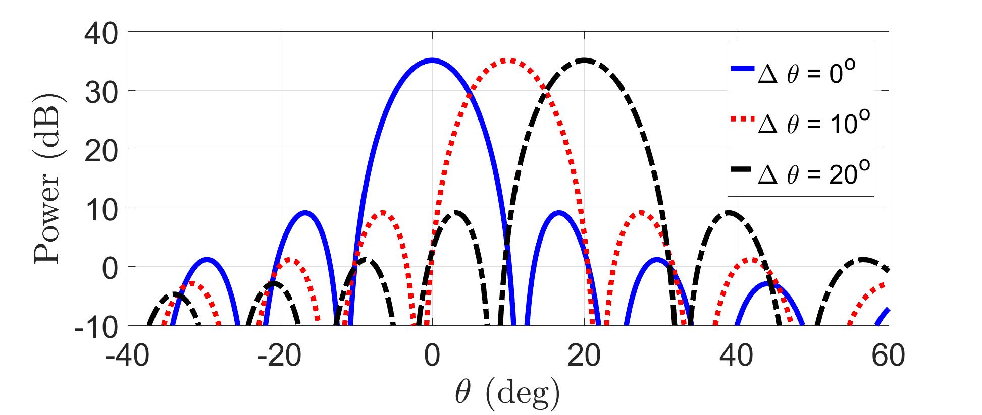
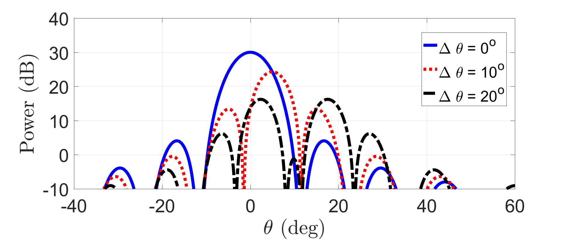
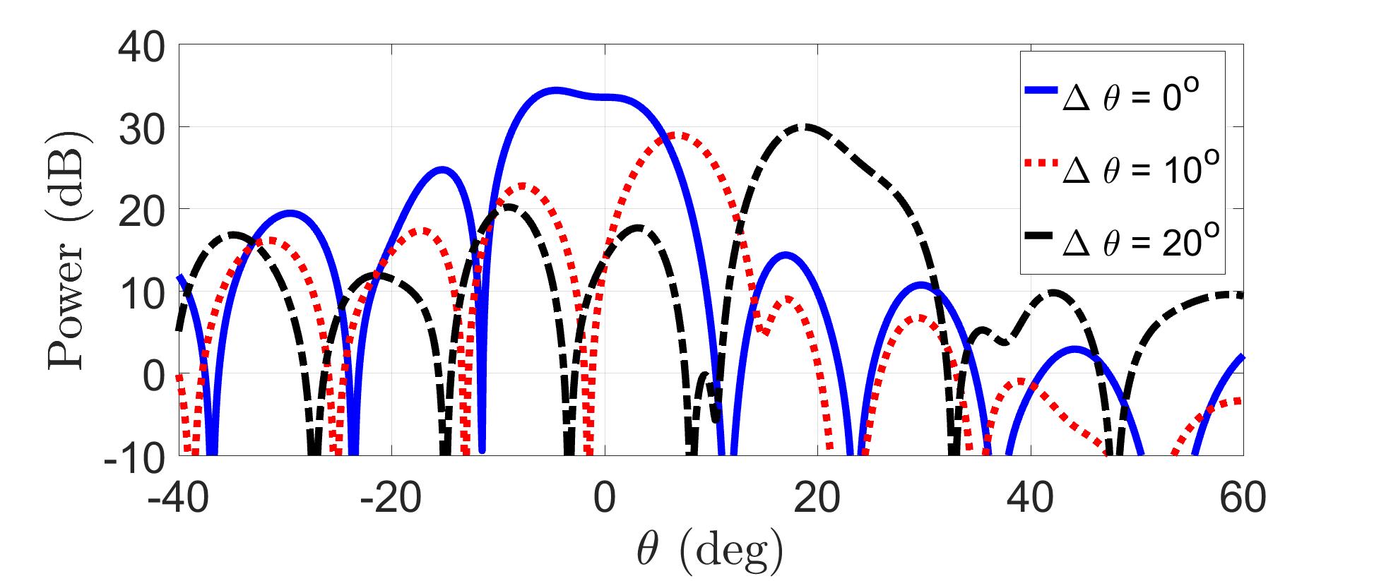
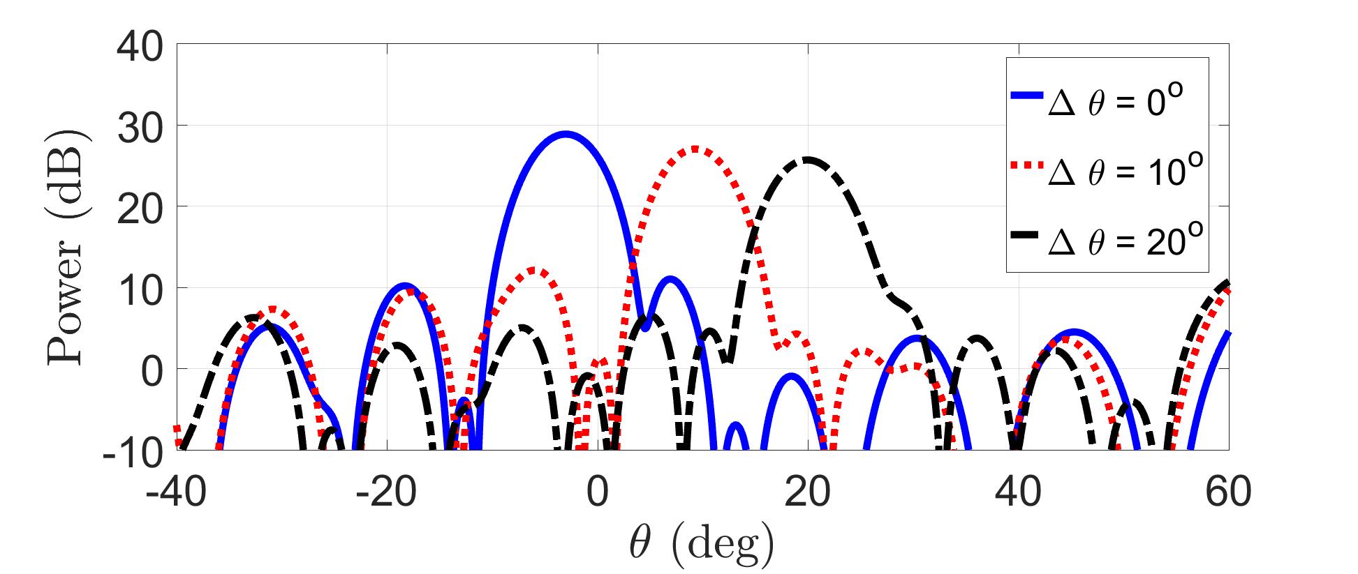
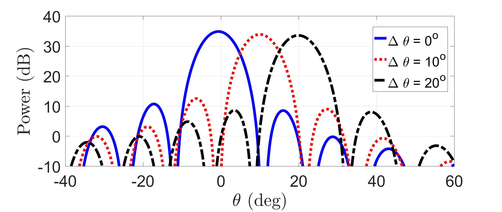
Fig. 7 shows the pattern GTR(θ,θ0)subscript𝐺𝑇𝑅𝜃subscript𝜃0G_{TR}(\theta,\theta_{0}) for (a) LFM (𝐑s=N𝐈Msubscript𝐑𝑠𝑁subscript𝐈𝑀\mathbf{R}_{s}=N\mathbf{I}_{M}), (b) Coherent Transmission, (c) WBFIT, (d) IA-CPC, and (e) PDR (α=200𝛼200\alpha=200) signals where the beam in the transmit mode is directed to θ=125𝜃superscript125\theta=125^{\circ} and the true location of the target is such that Δθ=(θθ0)=0, 10, 20formulae-sequenceΔ𝜃𝜃subscript𝜃0superscript0superscript10superscript20\Delta\theta=(\theta-\theta_{0})=0^{\circ},\ 10^{\circ},\ 20^{\circ}. The desired beampattern for this simulation is the same as Case 1 in Section IV-A, except that PDR was now optimized to generate orthogonal waveforms.

The advantage of using orthogonal signals (LFM) over a coherent scheme is very noticeable: the gain loss is nonexistent for LFM when the target deviates from the transmission direction (i.e., target is not located in the center of the transmit beam). Remarkably, PDR signals with α=200𝛼200\alpha=200 achieve results comparable to the LFM case, whereas in the absence of orthogonal processing, WBFIT in Fig. 7 (c) and IA-CPC in Fig. 7 (d) like the coherent case in Fig. 7 (b) suffer significant loss in mainlobe strength under target direction mismatch.

The focus of our work is on transmit waveform design but in future investigations, receive processing may also be optimized to obtain the most desirable transmit-receive beampattern.

Refer to caption
(a) LFM
Refer to caption
(b) Coherent Transmission
Refer to caption
(c) WBFIT [8]
Refer to caption
(d) IA-CPC [33]
Refer to caption
(e) PDR α=200𝛼200\alpha=200
Figure 7: The pattern GTR(θ,θd)subscript𝐺𝑇𝑅𝜃subscript𝜃𝑑G_{TR}(\theta,\theta_{d}) for (a) LFM, (b) Coherent, (c) WBFIT, and (d) PDR (α=200𝛼200\alpha=200) signals. The beam in the transmit mode is directed to θ=0𝜃superscript0\theta=0^{\circ} and the target is located at θ0=0, 10, 20subscript𝜃0superscript0superscript10superscript20\theta_{0}=0^{\circ},\ 10^{\circ},\ 20^{\circ}.

V Discussions and Conclusion

We consider the problem of transmit beampattern design for MIMO radar under compelling practical constraints. The non-convex constant modulus constraint (CMC) is our main focus whose presence is known to yield a hard optimization problem. For tractability, CMC is addressed in the literature often by relaxations and approximations or by approaches that are computationally burdensome. Our proposed PDR algorithm invokes the principles of optimization over manifolds to address the non-convex CMC and we demonstrate via simulations that the said PDR offers a favorable performance-complexity trade-off. Analytical guarantees of monotonic cost function decrease and convergence are provided for quadratic cost functions that arise in beampattern design. Finally, a tractable extension was developed to incorporate orthogonality of waveforms across antennas. Experimentally, the benefit of orthogonality combined with CMC is the synthesis of practical, real-world waveforms that demonstrate robustness to target direction mismatch.

A viable future work direction is to exploit for CMC constrained beampattern design new algorithms that use the framework of the sequential approximation such as [47] and recent advances in [48], [28]. Of particular interest is investigating KKT optimality of the resulting solution.

Acknowledgement

The authors would like to thank the authors of the work [33] for providing us with the MATLAB code for the Iterative Algorithm for Continuous Phase Case (IA-CPC) algorithm.

Appendix A Appendix A

In this section we provide the proof of the three lemmas that presented in this work and the equivalence between Eq (42) and the retraction step.

A-A Proof of Lemma III.1

Before we establish the proof, the projection operator in Eq (19) will be reformulated as follows. The projection of a vector 𝐰L𝐰superscript𝐿\mathbf{w}\in\mathbb{C}^{L} onto the tangent space 𝒯𝐳𝒮Lsubscript𝒯𝐳superscript𝒮𝐿\mathcal{T}_{\mathbf{z}}\mathcal{S}^{L} at a point 𝐳𝒮L𝐳superscript𝒮𝐿\mathbf{z}\in\mathcal{S}^{L} can be rewritten using the elementary properties the Hadamard product and the fact that Re{𝐰𝐳}=12[𝐰𝐳+𝐰𝐳]Redirect-productsuperscript𝐰𝐳12delimited-[]direct-productsuperscript𝐰𝐳direct-product𝐰superscript𝐳\text{Re}\{\mathbf{w}^{*}\odot\mathbf{z}\}=\frac{1}{2}\big{[}\mathbf{w}^{*}\odot\mathbf{z}+\mathbf{w}\odot\mathbf{z}^{*}\big{]} as

𝐏𝒯𝐳𝒮L(𝐰)subscript𝐏subscript𝒯𝐳superscript𝒮𝐿𝐰\displaystyle\mathbf{P}_{\mathcal{T}_{\mathbf{z}}\mathcal{S}^{L}}(\mathbf{w}) =\displaystyle= 𝐰12[𝐰𝐳+𝐰𝐳]𝐳𝐰direct-product12delimited-[]direct-productsuperscript𝐰𝐳direct-product𝐰superscript𝐳𝐳\displaystyle\mathbf{w}-\frac{1}{2}\big{[}\mathbf{w}^{*}\odot\mathbf{z}+\mathbf{w}\odot\mathbf{z}^{*}\big{]}\odot\mathbf{z} (34)
=\displaystyle= 𝐰12[𝐰𝐳𝐳+𝐰𝐳𝐳]𝐰12delimited-[]direct-productsuperscript𝐰𝐳𝐳direct-product𝐰superscript𝐳𝐳\displaystyle\mathbf{w}-\frac{1}{2}\big{[}\mathbf{w}^{*}\odot\mathbf{z}\odot\mathbf{z}+\mathbf{w}\odot\mathbf{z}^{*}\odot\mathbf{z}\big{]}
=\displaystyle= 𝐰12[ddiag(𝐳𝐳T)𝐰+𝐰]𝐰12delimited-[]ddiagsuperscript𝐳𝐳𝑇superscript𝐰𝐰\displaystyle\mathbf{w}-\frac{1}{2}\big{[}\text{ddiag}(\mathbf{z}\mathbf{z}^{T})\mathbf{w}^{*}+\mathbf{w}\big{]}
=\displaystyle= 12(𝐰𝐃𝐳𝐰)=12(𝐰𝐰~)12𝐰subscript𝐃𝐳superscript𝐰12𝐰~𝐰\displaystyle\frac{1}{2}\big{(}\mathbf{w}-\mathbf{D}_{\mathbf{z}}\mathbf{w}^{*}\big{)}=\frac{1}{2}\big{(}\mathbf{w}-\tilde{\mathbf{w}}\big{)}

where 𝐃𝐳=ddiag(𝐳𝐳T)subscript𝐃𝐳ddiagsuperscript𝐳𝐳𝑇\mathbf{D}_{\mathbf{z}}=\text{ddiag}(\mathbf{z}\mathbf{z}^{T}), and 𝐰~=𝐃𝐳𝐰~𝐰subscript𝐃𝐳superscript𝐰\tilde{\mathbf{w}}=\mathbf{D}_{\mathbf{z}}\mathbf{w}^{*}. Note that since 𝐳𝒮L𝐳superscript𝒮𝐿\mathbf{z}\in\mathcal{S}^{L}, then 𝐃𝐳H𝐃𝐳=𝐃𝐳𝐃𝐳H=𝐈superscriptsubscript𝐃𝐳𝐻subscript𝐃𝐳subscript𝐃𝐳superscriptsubscript𝐃𝐳𝐻𝐈\mathbf{D}_{\mathbf{z}}^{H}\mathbf{D}_{\mathbf{z}}=\mathbf{D}_{\mathbf{z}}\mathbf{D}_{\mathbf{z}}^{H}=\mathbf{I}, and hence

𝐰~H𝐰~=𝐰H𝐰superscript~𝐰𝐻~𝐰superscript𝐰𝐻𝐰\tilde{\mathbf{w}}^{H}\tilde{\mathbf{w}}=\mathbf{w}^{H}\mathbf{w} (35)

For notation simplicity, will use 𝐰𝐰\mathbf{w} instead of 𝐱f¯(𝐱(k))subscript𝐱¯𝑓subscript𝐱𝑘\nabla_{\mathbf{x}}\bar{f}(\mathbf{x}_{(k)}) to represent the gradient of f¯(𝐱)¯𝑓𝐱\bar{f}(\mathbf{x}) defined in Eq (12) at iteration k𝑘k, i.e., 𝐰=𝐱f¯(𝐱(k))=2𝐑𝐱(k)2𝐪𝐰subscript𝐱¯𝑓subscript𝐱𝑘2subscript𝐑𝐱𝑘2𝐪\mathbf{w}=\nabla_{\mathbf{x}}\bar{f}(\mathbf{x}_{(k)})=2\mathbf{R}\mathbf{x}_{(k)}-2{\mathbf{q}}, and hence the search direction 𝜼(k)subscript𝜼𝑘\boldsymbol{\eta}_{(k)} will be

𝜼(k)=𝐰subscript𝜼𝑘𝐰\boldsymbol{\eta}_{(k)}=-\mathbf{w}

The projection of the search direction 𝜼(k)subscript𝜼𝑘\boldsymbol{\eta}_{(k)} onto the tangent space 𝒯𝐱(k)𝒮Lsubscript𝒯subscript𝐱𝑘superscript𝒮𝐿\mathcal{T}_{\mathbf{x}_{(k)}}\mathcal{S}^{L} at a point 𝐱(k)subscript𝐱𝑘\mathbf{x}_{(k)} will be computed using the new projection formula Eq (34), and with a step β𝛽\beta along this direction starting from 𝐱(k)subscript𝐱𝑘\mathbf{x}_{(k)}, the update on the tangent space will be

𝐱¯(k)subscript¯𝐱𝑘\displaystyle\bar{\mathbf{x}}_{(k)} =\displaystyle= 𝐱(k)+β𝐏𝒯𝐱(k)𝒮L(𝜼(k))subscript𝐱𝑘𝛽subscript𝐏subscript𝒯subscript𝐱𝑘superscript𝒮𝐿subscript𝜼𝑘\displaystyle\mathbf{x}_{(k)}+\beta\mathbf{P}_{\mathcal{T}_{\mathbf{x}_{(k)}}\mathcal{S}^{L}}(\boldsymbol{\eta}_{(k)}) (36)
=\displaystyle= 𝐱(k)+β𝐏𝒯𝐱(k)𝒮L(𝐰)subscript𝐱𝑘𝛽subscript𝐏subscript𝒯subscript𝐱𝑘superscript𝒮𝐿𝐰\displaystyle\mathbf{x}_{(k)}+\beta\mathbf{P}_{\mathcal{T}_{\mathbf{x}_{(k)}}\mathcal{S}^{L}}(-\mathbf{w})
=\displaystyle= 𝐱(k)β2(𝐰𝐰~)subscript𝐱𝑘𝛽2𝐰~𝐰\displaystyle\mathbf{x}_{(k)}-\frac{\beta}{2}\big{(}\mathbf{w}-\tilde{\mathbf{w}}\big{)}
Proof:

Let 𝐑=𝐏+γ𝐈𝐑𝐏𝛾𝐈\mathbf{R}=\mathbf{P}+\gamma\mathbf{I}, the value of the cost function f¯(𝐱)=𝐱H𝐑𝐱𝐪H𝐱𝐱H𝐪¯𝑓𝐱superscript𝐱𝐻𝐑𝐱superscript𝐪𝐻𝐱superscript𝐱𝐻𝐪\bar{f}(\mathbf{x})=\mathbf{x}^{H}\mathbf{R}\mathbf{x}-\mathbf{q}^{H}\mathbf{x}-\mathbf{x}^{H}\mathbf{q} on the tangent space at the point 𝐱¯(k)subscript¯𝐱𝑘\bar{\mathbf{x}}_{(k)} (using the value of 𝐱¯(k)subscript¯𝐱𝑘\bar{\mathbf{x}}_{(k)} in Eq (36)) will be

f¯(𝐱¯(k))¯𝑓subscript¯𝐱𝑘\displaystyle\bar{f}(\bar{\mathbf{x}}_{(k)}) =\displaystyle= 𝐱(k)H𝐑𝐱(k)superscriptsubscript𝐱𝑘𝐻subscript𝐑𝐱𝑘\displaystyle\mathbf{x}_{(k)}^{H}\mathbf{R}\mathbf{x}_{(k)}
β2𝐱(k)H𝐑(𝐰𝐰~)β2(𝐰𝐰~)H𝐑𝐱(k)𝛽2superscriptsubscript𝐱𝑘𝐻𝐑𝐰~𝐰𝛽2superscript𝐰~𝐰𝐻subscript𝐑𝐱𝑘\displaystyle-\frac{\beta}{2}\mathbf{x}_{(k)}^{H}\mathbf{R}(\mathbf{w}-\tilde{\mathbf{w}})-\frac{\beta}{2}(\mathbf{w}-\tilde{\mathbf{w}})^{H}\mathbf{R}\mathbf{x}_{(k)}
+β24(𝐰𝐰~)H𝐑(𝐰𝐰~)𝐪H𝐱(k)superscript𝛽24superscript𝐰~𝐰𝐻𝐑𝐰~𝐰superscript𝐪𝐻subscript𝐱𝑘\displaystyle+\frac{\beta^{2}}{4}(\mathbf{w}-\tilde{\mathbf{w}})^{H}\mathbf{R}(\mathbf{w}-\tilde{\mathbf{w}})-\mathbf{q}^{H}\mathbf{x}_{(k)}
+β2𝐪H(𝐰𝐰~)𝐱(k)H𝐪+β2(𝐰𝐰~)H𝐪𝛽2superscript𝐪𝐻𝐰~𝐰superscriptsubscript𝐱𝑘𝐻𝐪𝛽2superscript𝐰~𝐰𝐻𝐪\displaystyle+\frac{\beta}{2}\mathbf{q}^{H}(\mathbf{w}-\tilde{\mathbf{w}})-\mathbf{x}_{(k)}^{H}\mathbf{q}+\frac{\beta}{2}(\mathbf{w}-\tilde{\mathbf{w}})^{H}\mathbf{q}
=\displaystyle= 𝐱(k)H𝐑𝐱(k)β4𝐰H(𝐰𝐰~)β4(𝐰𝐰~)H𝐰superscriptsubscript𝐱𝑘𝐻subscript𝐑𝐱𝑘𝛽4superscript𝐰𝐻𝐰~𝐰𝛽4superscript𝐰~𝐰𝐻𝐰\displaystyle\mathbf{x}_{(k)}^{H}\mathbf{R}\mathbf{x}_{(k)}-\frac{\beta}{4}\mathbf{w}^{H}(\mathbf{w}-\tilde{\mathbf{w}})-\frac{\beta}{4}(\mathbf{w}-\tilde{\mathbf{w}})^{H}\mathbf{w}
+β24(𝐰𝐰~)H𝐑(𝐰𝐰~)𝐪H𝐱(k)𝐱(k)H𝐪superscript𝛽24superscript𝐰~𝐰𝐻𝐑𝐰~𝐰superscript𝐪𝐻subscript𝐱𝑘superscriptsubscript𝐱𝑘𝐻𝐪\displaystyle+\frac{\beta^{2}}{4}(\mathbf{w}-\tilde{\mathbf{w}})^{H}\mathbf{R}(\mathbf{w}-\tilde{\mathbf{w}})-\mathbf{q}^{H}\mathbf{x}_{(k)}-\mathbf{x}_{(k)}^{H}\mathbf{q}

Now, the difference f¯(𝐱(k))f¯(𝐱¯(k))¯𝑓subscript𝐱𝑘¯𝑓subscript¯𝐱𝑘\bar{f}(\mathbf{x}_{(k)})-\bar{f}(\bar{\mathbf{x}}_{(k)}) will be

f¯(𝐱(k))f¯(𝐱¯(k))¯𝑓subscript𝐱𝑘¯𝑓subscript¯𝐱𝑘\displaystyle\bar{f}(\mathbf{x}_{(k)})-\bar{f}(\bar{\mathbf{x}}_{(k)}) =\displaystyle= β4𝐰H(𝐰𝐰~)+β4(𝐰𝐰~)H𝐰𝛽4superscript𝐰𝐻𝐰~𝐰𝛽4superscript𝐰~𝐰𝐻𝐰\displaystyle\frac{\beta}{4}\mathbf{w}^{H}(\mathbf{w}-\tilde{\mathbf{w}})+\frac{\beta}{4}(\mathbf{w}-\tilde{\mathbf{w}})^{H}\mathbf{w} (37)
β24(𝐰𝐰~)H𝐑(𝐰𝐰~)superscript𝛽24superscript𝐰~𝐰𝐻𝐑𝐰~𝐰\displaystyle-\frac{\beta^{2}}{4}(\mathbf{w}-\tilde{\mathbf{w}})^{H}\mathbf{R}(\mathbf{w}-\tilde{\mathbf{w}})
=\displaystyle= β4(𝐰H𝐰𝐰H𝐰~𝐰~H𝐰+𝐰~H𝐰~)𝛽4superscript𝐰𝐻𝐰superscript𝐰𝐻~𝐰superscript~𝐰𝐻𝐰superscript~𝐰𝐻~𝐰\displaystyle\frac{\beta}{4}\big{(}\mathbf{w}^{H}\mathbf{w}-\mathbf{w}^{H}\tilde{\mathbf{w}}-\tilde{\mathbf{w}}^{H}\mathbf{w}+\tilde{\mathbf{w}}^{H}\tilde{\mathbf{w}}\big{)}
β24(𝐰𝐰~)H𝐑(𝐰𝐰~)superscript𝛽24superscript𝐰~𝐰𝐻𝐑𝐰~𝐰\displaystyle-\frac{\beta^{2}}{4}(\mathbf{w}-\tilde{\mathbf{w}})^{H}\mathbf{R}(\mathbf{w}-\tilde{\mathbf{w}})
=\displaystyle= β4(𝐰𝐰~)H(𝐈β𝐑)(𝐰𝐰~)𝛽4superscript𝐰~𝐰𝐻𝐈𝛽𝐑𝐰~𝐰\displaystyle\frac{\beta}{4}(\mathbf{w}-\tilde{\mathbf{w}})^{H}(\mathbf{I}-\beta\mathbf{R})(\mathbf{w}-\tilde{\mathbf{w}}) (38)

where in Eq (37) the observation in Eq (35) is used.

Recall the definition of the matrix 𝐏=p𝐅pH𝐀pH𝐀p𝐅p𝐏subscript𝑝subscriptsuperscript𝐅𝐻𝑝subscriptsuperscript𝐀𝐻𝑝subscript𝐀𝑝subscript𝐅𝑝\mathbf{P}=\sum_{p}\mathbf{F}^{H}_{p}\mathbf{A}^{H}_{p}\mathbf{A}_{p}\mathbf{F}_{p}, for each p𝑝p the matrix (𝐀p𝐅p)H(𝐀p𝐅p)superscriptsubscript𝐀𝑝subscript𝐅𝑝𝐻subscript𝐀𝑝subscript𝐅𝑝(\mathbf{A}_{p}\mathbf{F}_{p})^{H}(\mathbf{A}_{p}\mathbf{F}_{p}) is positive semi definite, i.e., 𝐲H(𝐀p𝐅p)H(𝐀p𝐅p)𝐲=𝐀p𝐅p𝐲220𝐲Lsuperscript𝐲𝐻superscriptsubscript𝐀𝑝subscript𝐅𝑝𝐻subscript𝐀𝑝subscript𝐅𝑝𝐲subscriptsuperscriptnormsubscript𝐀𝑝subscript𝐅𝑝𝐲220for-all𝐲superscript𝐿\mathbf{y}^{H}(\mathbf{A}_{p}\mathbf{F}_{p})^{H}(\mathbf{A}_{p}\mathbf{F}_{p})\mathbf{y}=\|\mathbf{A}_{p}\mathbf{F}_{p}\mathbf{y}\|^{2}_{2}\geq 0\ \forall\ \mathbf{y}\in\mathbb{C}^{L} and any non-negative linear combination of positive semidefinite matrices is positive semidefinite (Observation 7.1.3 [49]), then 𝐏𝐏\mathbf{P} is positive semidefinite. Since 𝐏𝐏\mathbf{P} is positive semidefinite, then 𝐑𝐑\mathbf{R} is positive definite. Now, using Theorem 7.1 in [50], the matrix 𝐑𝐑\mathbf{R} can be diagonalized as

𝐑=𝐔Λ𝐔H𝐑𝐔Λsuperscript𝐔𝐻\mathbf{R}=\mathbf{U}\Lambda\mathbf{U}^{H} (39)

where ΛΛ\Lambda is diagonal matrix with the eigenvalues of 𝐑𝐑\mathbf{R} in the main diagonal, and 𝐔𝐔\mathbf{U} is unitary, i.e., 𝐔H𝐔=𝐔𝐔H=𝐈superscript𝐔𝐻𝐔superscript𝐔𝐔𝐻𝐈\mathbf{U}^{H}\mathbf{U}=\mathbf{U}\mathbf{U}^{H}=\mathbf{I}.

Using Eq (39) in Eq (38) yields

f¯(𝐱(k))f¯(𝐱¯(k))¯𝑓subscript𝐱𝑘¯𝑓subscript¯𝐱𝑘\displaystyle\bar{f}(\mathbf{x}_{(k)})-\bar{f}(\bar{\mathbf{x}}_{(k)}) =\displaystyle= β4(𝐰𝐰~)H(𝐈β𝐔Λ𝐔H)(𝐰𝐰~)𝛽4superscript𝐰~𝐰𝐻𝐈𝛽𝐔Λsuperscript𝐔𝐻𝐰~𝐰\displaystyle\frac{\beta}{4}(\mathbf{w}-\tilde{\mathbf{w}})^{H}(\mathbf{I}-\beta\mathbf{U}\Lambda\mathbf{U}^{H})(\mathbf{w}-\tilde{\mathbf{w}}) (40)
=\displaystyle= β4(𝐰𝐰~)H𝐔(𝐈βΛ)𝐔H(𝐰𝐰~)𝛽4superscript𝐰~𝐰𝐻𝐔𝐈𝛽Λsuperscript𝐔𝐻𝐰~𝐰\displaystyle\frac{\beta}{4}(\mathbf{w}-\tilde{\mathbf{w}})^{H}\mathbf{U}(\mathbf{I}-\beta\Lambda)\mathbf{U}^{H}(\mathbf{w}-\tilde{\mathbf{w}})
=\displaystyle= β4𝐡H(𝐈βΛ)𝐡𝛽4superscript𝐡𝐻𝐈𝛽Λ𝐡\displaystyle\frac{\beta}{4}\mathbf{h}^{H}(\mathbf{I}-\beta\Lambda)\mathbf{h}

where 𝐡=𝐔H(𝐰𝐰~)L𝐡superscript𝐔𝐻𝐰~𝐰superscript𝐿\mathbf{h}=\mathbf{U}^{H}(\mathbf{w}-\tilde{\mathbf{w}})\in\mathbb{C}^{L}. If the step β𝛽\beta is chosen in a way such that β4𝐡H(𝐈βΛ)𝐡0𝐡𝛽4superscript𝐡𝐻𝐈𝛽Λ𝐡0for-all𝐡\frac{\beta}{4}\mathbf{h}^{H}(\mathbf{I}-\beta\Lambda)\mathbf{h}\geq 0\ \forall\ \mathbf{h} or the matrix (𝐈βΛ)𝐈𝛽Λ(\mathbf{I}-\beta\Lambda) is positive semi-definite and β0𝛽0\beta\geq 0, then f¯(𝐱)f¯(𝐱¯)¯𝑓𝐱¯𝑓¯𝐱\bar{f}(\mathbf{x})-\bar{f}(\bar{\mathbf{x}}) will be non-negative. Then, the following condition on β𝛽\beta must be satisfied

𝐈βΛ0β1λ𝐑𝐈𝛽Λ0𝛽1subscript𝜆𝐑\mathbf{I}-\beta\Lambda\geq 0\Leftrightarrow\beta\leq\frac{1}{\lambda_{\mathbf{R}}} (41)

where λ𝐑subscript𝜆𝐑\lambda_{\mathbf{R}} is the largest eigenvalue of the matrix 𝐑𝐑\mathbf{R} (λ𝐑>0subscript𝜆𝐑0\lambda_{\mathbf{R}}>0 since 𝐑𝐑\mathbf{R} is positive definite). ∎

A-B Proof of Lemma III.2

Proof:

: Recall that the input to retraction operator , 𝐱¯(k)subscript¯𝐱𝑘\bar{\mathbf{x}}_{(k)}, is the update of 𝐱(k)subscript𝐱𝑘\mathbf{x}_{(k)} on the tangent space, i.e., 𝐱¯(k)𝒮Lsubscript¯𝐱𝑘superscript𝒮𝐿\bar{\mathbf{x}}_{(k)}\not\in\mathcal{S}^{L} and hence |x¯l(k)|1lsubscript¯𝑥𝑙𝑘1for-all𝑙|\bar{{x}}_{l(k)}|\geq 1\ \forall\ l. On the other hand, the output from the retraction step is a constant modulus point, i.e, 𝐱(k+1)=𝐑(𝐱¯(k))𝒮Lsubscript𝐱𝑘1𝐑subscript¯𝐱𝑘superscript𝒮𝐿\mathbf{x}_{(k+1)}=\mathbf{R}(\bar{\mathbf{x}}_{(k)})\in\mathcal{S}^{L}. Then, 𝐱¯(k)subscript¯𝐱𝑘\bar{\mathbf{x}}_{(k)} can be written in terms of 𝐱(k+1)subscript𝐱𝑘1\mathbf{x}_{(k+1)} as

𝐱¯(k)=𝐱(k+1)+Ψ𝐱(k+1)subscript¯𝐱𝑘subscript𝐱𝑘1Ψsubscript𝐱𝑘1\bar{\mathbf{x}}_{(k)}=\mathbf{x}_{(k+1)}+\Psi\mathbf{x}_{(k+1)} (42)

where Ψ=diag(ψ1,ψ2,,ψL)Ψdiagsubscript𝜓1subscript𝜓2subscript𝜓𝐿\Psi=\text{diag}(\psi_{1},\psi_{2},\ldots,\psi_{L}) is non-negative diagonal matrix. Note that Eq (42) is derived from the retraction step, see subsection A-D of this Appendix. Using Eq (42) the difference between the values of the cost function at 𝐱¯(k)subscript¯𝐱𝑘\bar{\mathbf{x}}_{(k)} and 𝐱(k+1)subscript𝐱𝑘1\mathbf{x}_{(k+1)} will be

f¯(𝐱¯(k))¯𝑓subscript¯𝐱𝑘\displaystyle\bar{f}(\bar{\mathbf{x}}_{(k)}) \displaystyle- f¯(𝐱(k+1))¯𝑓subscript𝐱𝑘1\displaystyle\bar{f}(\mathbf{x}_{(k+1)})
=\displaystyle= 𝐱(k+1)H(𝐏+γ𝐈)Ψ𝐱(k+1)superscriptsubscript𝐱𝑘1𝐻𝐏𝛾𝐈Ψsubscript𝐱𝑘1\displaystyle\mathbf{x}_{(k+1)}^{H}(\mathbf{P}+\gamma\mathbf{I})\Psi\mathbf{x}_{(k+1)} (44)
+𝐱(k+1)HΨ(𝐏+γ𝐈)𝐱(k+1)superscriptsubscript𝐱𝑘1𝐻Ψ𝐏𝛾𝐈subscript𝐱𝑘1\displaystyle+\mathbf{x}_{(k+1)}^{H}\Psi(\mathbf{P}+\gamma\mathbf{I})\mathbf{x}_{(k+1)}
+𝐱(k+1)HΨ(𝐏+γ𝐈)Ψ𝐱(k+1)superscriptsubscript𝐱𝑘1𝐻Ψ𝐏𝛾𝐈Ψsubscript𝐱𝑘1\displaystyle+\mathbf{x}_{(k+1)}^{H}\Psi(\mathbf{P}+\gamma\mathbf{I})\Psi\mathbf{x}_{(k+1)}
𝐪HΨ𝐱(k+1)𝐱(k+1)HΨ𝐪superscript𝐪𝐻Ψsubscript𝐱𝑘1superscriptsubscript𝐱𝑘1𝐻Ψ𝐪\displaystyle-\mathbf{q}^{H}\Psi\mathbf{x}_{(k+1)}-\mathbf{x}_{(k+1)}^{H}\Psi\mathbf{q}
=\displaystyle= 2γ𝐱(k+1)HΨ𝐱(k+1)+𝐱(k+1)H(Ψ𝐏+𝐏Ψ)𝐱(k+1)2𝛾superscriptsubscript𝐱𝑘1𝐻Ψsubscript𝐱𝑘1superscriptsubscript𝐱𝑘1𝐻Ψ𝐏𝐏Ψsubscript𝐱𝑘1\displaystyle 2\gamma\mathbf{x}_{(k+1)}^{H}\Psi\mathbf{x}_{(k+1)}+\mathbf{x}_{(k+1)}^{H}\big{(}\Psi\mathbf{P}+\mathbf{P}\Psi\big{)}\mathbf{x}_{(k+1)}
+𝐱(k+1)HΨ(𝐏+γ𝐈)Ψ𝐱(k+1)superscriptsubscript𝐱𝑘1𝐻Ψ𝐏𝛾𝐈Ψsubscript𝐱𝑘1\displaystyle+\>\mathbf{x}_{(k+1)}^{H}\Psi(\mathbf{P}+\gamma\mathbf{I})\Psi\mathbf{x}_{(k+1)}
𝐪HΨ𝐱(k+1)𝐱(k+1)HΨ𝐪superscript𝐪𝐻Ψsubscript𝐱𝑘1superscriptsubscript𝐱𝑘1𝐻Ψ𝐪\displaystyle-\mathbf{q}^{H}\Psi\mathbf{x}_{(k+1)}-\mathbf{x}_{(k+1)}^{H}\Psi\mathbf{q}
\displaystyle\geq  2γ𝐱(k+1)HΨ𝐱(k+1)+𝐱(k+1)H(Ψ𝐏+𝐏Ψ)𝐱(k+1)2𝛾superscriptsubscript𝐱𝑘1𝐻Ψsubscript𝐱𝑘1superscriptsubscript𝐱𝑘1𝐻Ψ𝐏𝐏Ψsubscript𝐱𝑘1\displaystyle\>2\gamma\mathbf{x}_{(k+1)}^{H}\Psi\mathbf{x}_{(k+1)}+\mathbf{x}_{(k+1)}^{H}\big{(}\Psi\mathbf{P}+\mathbf{P}\Psi\big{)}\mathbf{x}_{(k+1)}
𝐪HΨ𝐱(k+1)𝐱(k+1)HΨ𝐪superscript𝐪𝐻Ψsubscript𝐱𝑘1superscriptsubscript𝐱𝑘1𝐻Ψ𝐪\displaystyle-\>\mathbf{q}^{H}\Psi\mathbf{x}_{(k+1)}-\mathbf{x}_{(k+1)}^{H}\Psi\mathbf{q}
=\displaystyle=  2γΨ𝐱(k+1)1+𝐱(k+1)H(Ψ𝐏+𝐏Ψ)𝐱(k+1)2𝛾subscriptnormΨsubscript𝐱𝑘11superscriptsubscript𝐱𝑘1𝐻Ψ𝐏𝐏Ψsubscript𝐱𝑘1\displaystyle\>2\gamma\|\Psi\mathbf{x}_{(k+1)}\|_{1}+\mathbf{x}_{(k+1)}^{H}\big{(}\Psi\mathbf{P}+\mathbf{P}\Psi\big{)}\mathbf{x}_{(k+1)}
𝐪HΨ𝐱(k+1)𝐱(k+1)HΨ𝐪superscript𝐪𝐻Ψsubscript𝐱𝑘1superscriptsubscript𝐱𝑘1𝐻Ψ𝐪\displaystyle-\>\mathbf{q}^{H}\Psi\mathbf{x}_{(k+1)}-\mathbf{x}_{(k+1)}^{H}\Psi\mathbf{q}

The inequality Eq (44) holds since (𝐏+γ𝐈)𝐏𝛾𝐈(\mathbf{P}+\gamma\mathbf{I}) is positive semidefinite and the equality Eq (44) holds since 𝐱(k+1)HΨ𝐱(k+1)=Ψ𝐱(k+1)1superscriptsubscript𝐱𝑘1𝐻Ψsubscript𝐱𝑘1subscriptnormΨsubscript𝐱𝑘11\mathbf{x}_{(k+1)}^{H}\Psi\mathbf{x}_{(k+1)}=\|\Psi\mathbf{x}_{(k+1)}\|_{1} and this is true since 𝐱(k+1)subscript𝐱𝑘1\mathbf{x}_{(k+1)} is constant modulus vector. To go further in this simplification, and since 𝐏0𝐏0\mathbf{P}\geq 0 and Ψ0Ψ0\Psi\geq 0, the following theorem about (Ψ𝐏+𝐏Ψ)Ψ𝐏𝐏Ψ\big{(}\Psi\mathbf{P}+\mathbf{P}\Psi\big{)} (Theorem 7.5 in [50]) can be utilized

\IEEEeqnarraymulticol3l14λΨλ𝐏𝐈L(Ψ𝐏+𝐏Ψ)\IEEEeqnarraymulticol3𝑙14subscript𝜆Ψsubscript𝜆𝐏subscript𝐈𝐿Ψ𝐏𝐏Ψ\displaystyle\IEEEeqnarraymulticol{3}{l}{-\frac{1}{4}\lambda_{\Psi}\lambda_{\mathbf{P}}\mathbf{I}_{L}\leq\big{(}\Psi\mathbf{P}+\mathbf{P}\Psi\big{)}} (45)
\displaystyle\Rightarrow L4λΨλ𝐏𝐱(k+1)H(Ψ𝐏+𝐏Ψ)𝐱(k+1)𝐿4subscript𝜆Ψsubscript𝜆𝐏superscriptsubscript𝐱𝑘1𝐻Ψ𝐏𝐏Ψsubscript𝐱𝑘1\displaystyle-\frac{L}{4}\lambda_{\Psi}\lambda_{\mathbf{P}}\leq\mathbf{x}_{(k+1)}^{H}\big{(}\Psi\mathbf{P}+\mathbf{P}\Psi\big{)}\mathbf{x}_{(k+1)} (46)

where λΨsubscript𝜆Ψ\lambda_{\Psi} and λ𝐏subscript𝜆𝐏\lambda_{\mathbf{P}} are the largest eigenvalue of ΨΨ\Psi and 𝐏𝐏\mathbf{P}, respectively. Using Eq (46) in Eq (44) yields

f¯(𝐱¯(k))¯𝑓subscript¯𝐱𝑘\displaystyle\bar{f}(\bar{\mathbf{x}}_{(k)}) \displaystyle- f¯(𝐱(k+1))¯𝑓subscript𝐱𝑘1\displaystyle\bar{f}(\mathbf{x}_{(k+1)})
\displaystyle\geq 2γΨ𝐱(k+1)1L4λΨλ𝐏2𝛾subscriptnormΨsubscript𝐱𝑘11𝐿4subscript𝜆Ψsubscript𝜆𝐏\displaystyle 2\gamma\|\Psi\mathbf{x}_{(k+1)}\|_{1}-\frac{L}{4}\lambda_{\Psi}\lambda_{\mathbf{P}}
𝐪HΨ𝐱(k+1)𝐱(k+1)HΨ𝐪superscript𝐪𝐻Ψsubscript𝐱𝑘1superscriptsubscript𝐱𝑘1𝐻Ψ𝐪\displaystyle-\>\mathbf{q}^{H}\Psi\mathbf{x}_{(k+1)}-\mathbf{x}_{(k+1)}^{H}\Psi\mathbf{q}
=\displaystyle= 2γΨ𝐱(k+1)1L4λ𝐏Ψ𝐱(k+1)2𝛾subscriptnormΨsubscript𝐱𝑘11𝐿4subscript𝜆𝐏subscriptnormΨsubscript𝐱𝑘1\displaystyle 2\gamma\|\Psi\mathbf{x}_{(k+1)}\|_{1}-\frac{L}{4}\lambda_{\mathbf{P}}\|\Psi\mathbf{x}_{(k+1)}\|_{\infty}
𝐪HΨ𝐱(k+1)𝐱(k+1)HΨ𝐪superscript𝐪𝐻Ψsubscript𝐱𝑘1superscriptsubscript𝐱𝑘1𝐻Ψ𝐪\displaystyle-\>\mathbf{q}^{H}\Psi\mathbf{x}_{(k+1)}-\mathbf{x}_{(k+1)}^{H}\Psi\mathbf{q}
\displaystyle\geq  2γΨ𝐱(k+1)1L4λ𝐏Ψ𝐱(k+1)12𝛾subscriptnormΨsubscript𝐱𝑘11𝐿4subscript𝜆𝐏subscriptnormΨsubscript𝐱𝑘11\displaystyle\>2\gamma\|\Psi\mathbf{x}_{(k+1)}\|_{1}-\frac{L}{4}\lambda_{\mathbf{P}}\|\Psi\mathbf{x}_{(k+1)}\|_{1}
 2Ψ𝐱(k+1)2𝐪22subscriptnormΨsubscript𝐱𝑘12subscriptnorm𝐪2\displaystyle-\>2\|\Psi\mathbf{x}_{(k+1)}\|_{2}\|\mathbf{q}\|_{2}
\displaystyle\geq  2γΨ𝐱(k+1)1L4λ𝐏Ψ𝐱(k+1)12𝛾subscriptnormΨsubscript𝐱𝑘11𝐿4subscript𝜆𝐏subscriptnormΨsubscript𝐱𝑘11\displaystyle\>2\gamma\|\Psi\mathbf{x}_{(k+1)}\|_{1}-\frac{L}{4}\lambda_{\mathbf{P}}\|\Psi\mathbf{x}_{(k+1)}\|_{1}
 2Ψ𝐱(k+1)1𝐪22subscriptnormΨsubscript𝐱𝑘11subscriptnorm𝐪2\displaystyle-\>2\|\Psi\mathbf{x}_{(k+1)}\|_{1}\|\mathbf{q}\|_{2}
=\displaystyle= (L4λ𝐏+2𝐪2)Ψ𝐱(k+1)1𝐿4subscript𝜆𝐏2subscriptnorm𝐪2subscriptnormΨsubscript𝐱𝑘11\displaystyle\>-\Big{(}\frac{L}{4}\lambda_{\mathbf{P}}+2\|\mathbf{q}\|_{2}\Big{)}\|\Psi\mathbf{x}_{(k+1)}\|_{1}
+2γΨ𝐱(k+1)12𝛾subscriptnormΨsubscript𝐱𝑘11\displaystyle\>+2\gamma\|\Psi\mathbf{x}_{(k+1)}\|_{1}
=\displaystyle= (2γL4λ𝐏2𝐪2)Ψ𝐱(k+1)12𝛾𝐿4subscript𝜆𝐏2subscriptnorm𝐪2subscriptnormΨsubscript𝐱𝑘11\displaystyle\>\big{(}2\gamma-\frac{L}{4}\lambda_{\mathbf{P}}-2\|\mathbf{q}\|_{2}\big{)}\|\Psi\mathbf{x}_{(k+1)}\|_{1} (52)
\displaystyle\geq  0 0\displaystyle\>0 (53)

where Eq (A-B) holds from Eq (46), Eq (A-B) holds since Ψ𝐱(k+1)=maxl|ψlxl(k+1)|=λΨsubscriptnormΨsubscript𝐱𝑘1subscriptmax𝑙subscript𝜓𝑙subscript𝑥𝑙𝑘1subscript𝜆Ψ\|\Psi\mathbf{x}_{(k+1)}\|_{\infty}=\text{max}_{l}|\psi_{l}x_{l(k+1)}|=\lambda_{\Psi}, Eq (A-B) holds since Ψ𝐱(k+1)Ψ𝐱(k+1)1subscriptnormΨsubscript𝐱𝑘1subscriptnormΨsubscript𝐱𝑘11\|\Psi\mathbf{x}_{(k+1)}\|_{\infty}\leq\|\Psi\mathbf{x}_{(k+1)}\|_{1}, Eq (A-B) holds since 𝐪HΨ𝐱(k+1)Ψ𝐱(k+1)2𝐪2superscript𝐪𝐻Ψsubscript𝐱𝑘1subscriptnormΨsubscript𝐱𝑘12subscriptnorm𝐪2\mathbf{q}^{H}\Psi\mathbf{x}_{(k+1)}\leq\|\Psi\mathbf{x}_{(k+1)}\|_{2}\|\mathbf{q}\|_{2}, Eq (A-B) holds since Ψ𝐱(k+1)2Ψ𝐱(k+1)1subscriptnormΨsubscript𝐱𝑘12subscriptnormΨsubscript𝐱𝑘11\|\Psi\mathbf{x}_{(k+1)}\|_{2}\leq\|\Psi\mathbf{x}_{(k+1)}\|_{1}, and finally Eq (53) holds if

γL8λ𝐏+𝐪2𝛾𝐿8subscript𝜆𝐏subscriptnorm𝐪2\gamma\geq\frac{L}{8}\lambda_{\mathbf{P}}+\|\mathbf{q}\|_{2} (54)

A-C Proof of Lemma III.3

Proof:

: From Lemmas III.1 and III.2, we have

f¯(𝐱(k))f¯(𝐱(k+1))f¯(𝐱(k))f¯(𝐱(k+1))0¯𝑓subscript𝐱𝑘¯𝑓subscript𝐱𝑘1¯𝑓subscript𝐱𝑘¯𝑓subscript𝐱𝑘10\bar{f}(\mathbf{x}_{(k)})\geq\bar{f}(\mathbf{x}_{(k+1)})\Rightarrow\bar{f}(\mathbf{x}_{(k)})-\bar{f}(\mathbf{x}_{(k+1)})\geq 0 (55)

Since 𝐱(k)H𝐱(k)=𝐱(k+1)H𝐱(k+1)=Lsuperscriptsubscript𝐱𝑘𝐻subscript𝐱𝑘superscriptsubscript𝐱𝑘1𝐻subscript𝐱𝑘1𝐿\mathbf{x}_{(k)}^{H}\mathbf{x}_{(k)}=\mathbf{x}_{(k+1)}^{H}\mathbf{x}_{(k+1)}=L, then

f¯(𝐱(k))f¯(𝐱(k+1))=f(𝐱(k))f(𝐱(k+1))0¯𝑓subscript𝐱𝑘¯𝑓subscript𝐱𝑘1𝑓subscript𝐱𝑘𝑓subscript𝐱𝑘10\bar{f}(\mathbf{x}_{(k)})-\bar{f}(\mathbf{x}_{(k+1)})=f(\mathbf{x}_{(k)})-f(\mathbf{x}_{(k+1)})\geq 0 (56)

Then the sequence {f(𝐱(k))}k=0superscriptsubscript𝑓subscript𝐱𝑘𝑘0\{f(\mathbf{x}_{(k)})\}_{k=0}^{\infty} is non-increasing and since f(𝐱)0,𝐱𝑓𝐱0for-all𝐱f(\mathbf{x})\geq 0,\ \forall\ \mathbf{x} and hence it is bounded below, then it converges to a finite value fsuperscript𝑓f^{*}. ∎

A-D The equivalence between Eq (42) and the retraction step

In this subsection, we show the equivalence between Eq (42) and the retraction step (Step 5 in Algorithm 1). This Eq is used to write 𝐱¯(k)subscript¯𝐱𝑘\bar{\mathbf{x}}_{(k)} in terms of 𝐱(k+1)subscript𝐱𝑘1\mathbf{x}_{(k+1)}. Starting from the retraction formula, this equivalence can be shown as follows:

𝐱(k+1)subscript𝐱𝑘1\displaystyle\mathbf{x}_{(k+1)} =\displaystyle= 𝐑(𝐱¯(k))=𝐱¯(k)1|𝐱¯(k)|=Ψ¯𝐱¯(k)𝐑subscript¯𝐱𝑘direct-productsubscript¯𝐱𝑘1subscript¯𝐱𝑘¯Ψsubscript¯𝐱𝑘\displaystyle\mathbf{R}\big{(}\bar{\mathbf{x}}_{(k)}\big{)}=\bar{\mathbf{x}}_{(k)}\odot\frac{1}{|\bar{\mathbf{x}}_{(k)}|}=\bar{\Psi}\bar{\mathbf{x}}_{(k)} (57)

where Ψ¯=diag(1|x¯1(k)|,1|x¯2(k)|,,1|x¯L(k)|)¯Ψdiag1subscript¯𝑥1𝑘1subscript¯𝑥2𝑘1subscript¯𝑥𝐿𝑘\bar{\Psi}=\text{diag}\Big{(}\frac{1}{|\bar{x}_{1(k)}|},\frac{1}{|\bar{x}_{2(k)}|},\ldots,\frac{1}{|\bar{x}_{L(k)}|}\Big{)}. Solving for 𝐱¯(k)subscript¯𝐱𝑘\bar{\mathbf{x}}_{(k)} yields

𝐱¯(k)subscript¯𝐱𝑘\displaystyle\bar{\mathbf{x}}_{(k)} =\displaystyle= Ψ¯1𝐱(k+1)superscript¯Ψ1subscript𝐱𝑘1\displaystyle\bar{\Psi}^{-1}\mathbf{x}_{(k+1)} (58)

Since 𝐱¯(k)𝒯𝐱(k)𝒮Lsubscript¯𝐱𝑘subscript𝒯subscript𝐱𝑘superscript𝒮𝐿\bar{\mathbf{x}}_{(k)}\in\mathcal{T}_{\mathbf{x}_{(k)}}\mathcal{S}^{L} and hence |x¯l(k)|1,l=1,2,,Lformulae-sequencesubscript¯𝑥𝑙𝑘1𝑙12𝐿|\bar{{x}}_{l(k)}|\geq 1,\ l=1,2,\ldots,L, the quantity |x¯l(k)|subscript¯𝑥𝑙𝑘|\bar{{x}}_{l(k)}| can be written as |x¯l(k)|=1+ψlsubscript¯𝑥𝑙𝑘1subscript𝜓𝑙|\bar{{x}}_{l(k)}|=1+\psi_{l} with ψl0lsubscript𝜓𝑙0for-all𝑙\psi_{l}\geq 0\ \forall\ l. Using this, the matrix Ψ¯¯Ψ\bar{\Psi} will be Ψ¯=diag(11+ψ1,11+ψ2,,11+ψL)¯Ψdiag11subscript𝜓111subscript𝜓211subscript𝜓𝐿\bar{\Psi}=\text{diag}\Big{(}\frac{1}{1+\psi_{1}},\frac{1}{1+\psi_{2}},\ldots,\frac{1}{1+\psi_{L}}\Big{)}, the matrix Ψ¯1superscript¯Ψ1\bar{\Psi}^{-1} will be

Ψ¯1superscript¯Ψ1\displaystyle\bar{\Psi}^{-1} =\displaystyle= diag(1+ψ1,1+ψ2,,1+ψL)diag1subscript𝜓11subscript𝜓21subscript𝜓𝐿\displaystyle\text{diag}\Big{(}1+\psi_{1},1+\psi_{2},\ldots,1+\psi_{L}\Big{)} (59)
=\displaystyle= 𝐈L+Ψsubscript𝐈𝐿Ψ\displaystyle\mathbf{I}_{L}+\Psi

where Ψ=diag(ψ1,ψ2,,ψL)Ψdiagsubscript𝜓1subscript𝜓2subscript𝜓𝐿\Psi=\text{diag}\big{(}\psi_{1},\psi_{2},\ldots,\psi_{L}\big{)}. Substituting this value of Ψ¯1superscript¯Ψ1\bar{\Psi}^{-1} in Eq (58), the vector 𝐱¯(k)subscript¯𝐱𝑘\bar{\mathbf{x}}_{(k)} will be

𝐱¯(k)subscript¯𝐱𝑘\displaystyle\bar{\mathbf{x}}_{(k)} =\displaystyle= (𝐈L+Ψ)𝐱(k+1)subscript𝐈𝐿Ψsubscript𝐱𝑘1\displaystyle\big{(}\mathbf{I}_{L}+\Psi\big{)}\mathbf{x}_{(k+1)} (60)
=\displaystyle= 𝐱(k+1)+Ψ𝐱(k+1)subscript𝐱𝑘1Ψsubscript𝐱𝑘1\displaystyle\mathbf{x}_{(k+1)}+\Psi\mathbf{x}_{(k+1)}

Eq (60) hence reduces to Eq (42).

References

  • [1] W. Stutzman and G. Thiele, Antenna theory and design, John Wiley & Sons, 2012.
  • [2] D. R. Fuhrmann and G. San Antonio, “Transmit beamforming for MIMO radar systems using signal cross-correlation,” IEEE Trans. Aerosp. Electron. Syst., vol. 44, no. 1, pp. 171–186, 2008.
  • [3] J. Lipor, S. Ahmed, and M. S. Alouini, “Fourier-based transmit beampattern design using MIMO radar,” IEEE Trans. on Signal Process., vol. 62, no. 9, pp. 2226–2235, 2014.
  • [4] S. Ahmed and M. S. Alouini, “MIMO radar transmit beampattern design without synthesising the covariance matrix,” IEEE Trans. on Signal Process., vol. 62, no. 9, pp. 2278–2289, May 2014.
  • [5] Z. Cheng, Z. He, S. Zhang, and J. Li, “Constant modulus waveform design for MIMO radar transmit beampattern,” IEEE Trans. on Signal Process., vol. 65, no. 18, pp. 4912–4923, 2017.
  • [6] A. Aubry, A. De Maio, and Y. Huang, “MIMO radar beampattern design via PSL/ISL optimization,” IEEE Trans. on Signal Process., vol. 64, no. 15, pp. 3955–3967, 2016.
  • [7] G. San Antonio and D. R. Fuhrmann, “Beampattern synthesis for wideband MIMO radar systems,” in Computational Advances in Multi-Sensor Adaptive Processing, 2005 1st IEEE International Workshop on. IEEE, 2005, pp. 105–108.
  • [8] H. He, P. Stoica, and J. Li, “Wideband MIMO systems: signal design for transmit beampattern synthesis,” IEEE Trans. on Signal Process., vol. 59, no. 2, pp. 618–628, 2011.
  • [9] T. Yang, T. Su, and Z. Wu, “Fast frequency invariant transmit beampattern synthesis for wideband MIMO radar,” IET Conf. Proceed., 2012.
  • [10] P. Gong and Z. Shao, “Transmit beampattern synthesis with constant beamwidth and sidelobe control for wideband MIMO radar,” International Journal of Antennas and Propagation, vol. 2014, 2014.
  • [11] O. Aldayel, V. Monga, and M. Rangaswamy, “Tractable transmit MIMO beampattern design under a constant modulus constraint,” IEEE Trans. on Signal Process., vol. 65, no. 10, pp. 2588–2599, 2017.
  • [12] D. R. Fuhrmann and G. San Antonio, “Transmit beamforming for mimo radar systems using partial signal correlation,” in Conference Record of the Thirty-Eighth Asilomar Conference on Signals, Systems and Computers, 2004. IEEE, 2004, vol. 1, pp. 295–299.
  • [13] H. Li and B. Himed, “Transmit subaperturing for mimo radars with co-located antennas,” IEEE Journal of Selected Topics in Signal Processing, vol. 4, no. 1, pp. 55–65, 2010.
  • [14] J. Li and P. Stoica, MIMO radar Signal Process., Wiley Online Library, 2009.
  • [15] L. K. Patton, On the Satisfaction of Modulus and Ambiguity Function Constraints in Radar Waveform Optimization for Detection, Ph.D. thesis, Wright State University, June 2009.
  • [16] L. K. Patton and B. D. Rigling, “Modulus constraints in adaptive radar waveform design,” in Radar Conference. IEEE, 2008, pp. 1–6.
  • [17] P. Stoica, J. Li, and Y. Xie, “On probing signal design for MIMO radar,” IEEE Trans. on Signal Process., vol. 55, no. 8, pp. 4151–4161, 2007.
  • [18] A. Aubry, A. De Maio, M. Piezzo, and A. Farina, “Radar waveform design in a spectrally crowded environment via nonconvex quadratic optimization,” IEEE Trans. Aerosp. Electron. Syst., vol. 50, no. 2, pp. 1138–1152, 2014.
  • [19] Y. Wang, X. Wang, H. Liu, and Z. Luo, “On the design of constant modulus probing signals for MIMO radar,” IEEE Trans. on Signal Process., vol. 60, no. 8, pp. 4432–4438, 2012.
  • [20] Z. Luo, W. Ma, A. M. So, Y Ye, and S. Zhang, “Semidefinite relaxation of quadratic optimization problems,” IEEE Signal Process. Mag., vol. 27, no. 3, pp. 20–34, 2010.
  • [21] G. Cui, H. Li, and M. Rangaswamy, “MIMO radar waveform design with constant modulus and similarity constraints,” IEEE Trans. on Signal Process., vol. 62, no. 2, pp. 343–353, 2014.
  • [22] J. Chen, “Manifold optimization approach for data detection in massive multiuser MIMO systems,” IEEE Trans. on Vehicular Technology, vol. 67, no. 4, pp. 3652–3657, 2018.
  • [23] I. Bekkerman and J. Tabrikian, “Target detection and localization using MIMO radars and sonars,” IEEE Trans. on Signal Process., vol. 54, no. 10, pp. 3873–3883, 2006.
  • [24] E. Fishler, A. Haimovich, R. S. Blum, L. J. Cimini, D. Chizhik, and R. A. Valenzuela, “Spatial diversity in radars—models and detection performance,” IEEE Trans. on Signal Process., vol. 54, no. 3, pp. 823–838, 2006.
  • [25] J. Li, P. Stoica, L. Xu, and W. Roberts, “On parameter identifiability of MIMO radar,” IEEE Signal Process. Letters, vol. 14, no. 12, pp. 968–971, 2007.
  • [26] L. Xu, J. Li, and P. Stoica, “Target detection and parameter estimation for MIMO radar systems,” IEEE Trans. Aerosp. Electron. Syst., vol. 44, no. 3, pp. 927–939, 2008.
  • [27] H. He, P. Stoica, and J. Li, “Designing unimodular sequence sets with good correlations—including an application to MIMO radar,” IEEE Trans. on Signal Process., vol. 57, no. 11, pp. 4391–4405, 2009.
  • [28] J. Song, P. Babu, and D. P. Palomar, “Optimization methods for designing sequences with low autocorrelation sidelobes,” IEEE Trans. on Signal Process., vol. 63, no. 15, pp. 3998–4009, 2015.
  • [29] G. Cui, X. Yu, M. Piezzo, and L. Kong, “Constant modulus sequence set design with good correlation properties,” Signal Process., vol. 139, pp. 75–85, 2017.
  • [30] Y. Li and S. A. Vorobyov, “Fast algorithms for designing unimodular waveform (s) with good correlation properties,” IEEE Trans. on Signal Process., vol. 66, no. 5, pp. 1197–1212, 2018.
  • [31] H. Deng, Z. Geng, and B. Himed, “MIMO radar waveform design for transmit beamforming and orthogonality,” IEEE Trans. Aerosp. Electron. Syst., vol. 52, no. 3, pp. 1421–1433, 2016.
  • [32] M. Soltanalian and P. Stoica, “Designing unimodular codes via quadratic optimization.,” IEEE Trans. on Signal Process., vol. 62, no. 5, pp. 1221–1234, 2014.
  • [33] G. Cui, X. Yu, G. Foglia, Y. Huang, and J. Li, “Quadratic optimization with similarity constraint for unimodular sequence synthesis,” IEEE Trans. on Signal Process., vol. 65, no. 18, pp. 4756–4769, 2017.
  • [34] J. Liang, H. C. So, J. Li, and A. Farina, “Unimodular Sequence Design Based on Alternating Direction Method of Multipliers,” IEEE Trans. on Signal Process., vol. 64, no. 20, pp. 5367–5381, 2016.
  • [35] A. S. Bandeira, N. Boumal, and A. Singer, “Tightness of the maximum likelihood semidefinite relaxation for angular synchronization,” Mathematical Programming, vol. 163, no. 1-2, pp. 145–167, 2017.
  • [36] P.-A. Absil, R. Mahony, and R. Sepulchre, Optimization algorithms on matrix manifolds, Princeton University Press, 2009.
  • [37] A. Kovnatsky, K. Glashoff, and M. Bronstein, “MADMM: a generic algorithm for non-smooth optimization on manifolds,” in European Conference on Computer Vision. Springer, 2016, pp. 680–696.
  • [38] S. Sussman, “Least-square synthesis of radar ambiguity functions,” IRE Trans. on Information Theory, vol. 8, no. 3, pp. 246–254, 1962.
  • [39] R. W. Gerchberg and W. O. Saxton, “A Practical Algorithm for the Determination of Phase from Image and Diffraction Plane Pictures,” Optik, vol. 35, no. 2, pp. 237–246, 1972.
  • [40] Z. Wen and W. Yin, “A feasible method for optimization with orthogonality constraints,” Mathematical Programming, vol. 142, no. 1-2, pp. 397–434, 2013.
  • [41] B. Jiang and Y. Dai, “A framework of constraint preserving update schemes for optimization on stiefel manifold,” Mathematical Programming, vol. 153, no. 2, pp. 535–575, 2015.
  • [42] P. L. Fackler, “Notes on matrix calculus,” North Carolina State University, 2005.
  • [43] W. Rowe, P. Stoica, and J. Li, “Spectrally constrained waveform design,” IEEE Signal Process. Mag., vol. 31, no. 3, pp. 157–162, 2014.
  • [44] B. Kang, O. Aldayel, V. Monga, and M. Rangaswamy, “Spatio-spectral radar beampattern design for co-existence with wireless communication systems,” vol. 55, no. 2, pp. 644–657, 2019.
  • [45] N. Levanon and E. Mozeson, Radar signals, John Wiley & Sons, 2004.
  • [46] M. Richards, J. Scheer, W. Holm, and W. Melvin, Principles of modern radar, Citeseer, 2010.
  • [47] M. Razaviyayn, M. Hong, and Z. Luo, “A unified convergence analysis of block successive minimization methods for nonsmooth optimization,” SIAM Journal on Optimization, vol. 23, no. 2, pp. 1126–1153, 2013.
  • [48] A. Aubry, A. De Maio, A. Zappone, M. Razaviyayn, and Z. Luo, “A new sequential optimization procedure and its applications to resource allocation for wireless systems,” IEEE Trans. on Signal Process., vol. 66, no. 24, pp. 6518–6533, 2018.
  • [49] R. Horn and C. Johnson, Matrix analysis, Cambridge Uni. press, 1990.
  • [50] F. Zhang, Matrix theory: basic results and techniques, Springer Science & Business Media, 2011.