Seeing relativity – II. Revisiting and visualizing the Reissner-Nordström metric
Abstract
In this paper we study some features of the Reissner-Nordström metric both from an analytic and a visual point of view. We perform an accurate ray tracing and study of null geodesics in various situations. Among the issues we focus on are (i) the comparison with the Schwarzschild case, (ii) the naked singularity case, where, if the electric charge is not too large, some dark shell appears on images despite there is no horizon in the metric, and (iii) the wormhole crossing case, i.e., a visual exploration of the maximal analytic extension of the metric.
pacs:
03.30.+p, 04.25.D-I Introduction
The Reissner-Nordström (hereafter RN) metric is the second exact spherically symmetric solution to the Einstein equation that has been discovered independently by Hans Reissner reissner16 and Gunnar Nordström nordstrom18 , soon after the discovery of General Relativity. It describes the gravitational field of a pointlike mass possessing an electric charge . It is therefore the generalization of the Schwarzschild metric to the case of an electrically charged body. An exhaustive study of this metric has already been performed by various authors (see, e.g., chandrasekhar83 ), but most of these studies lacked to make an emphasis on the visual aspect of black hole, in contrast with the Schwarzschild (together with Kerr) metrics which have deserved a lot of attention because of their obvious astrophysical interest, see, e.g. Refs. fukue88 ; viergutz93 ; marck95 ; fanton97 ; falcke00 ; hamilton04 ; beckwith05 . These early papers simulated the view of the black hole and its accretion disk seen by a distant observer and were then transformed into what could be observed by some astronomical device, i.e., converted into a single pixel, with spectral and photometric informations. From an observational point of view, only two black holes exhibit a sufficiently large angular size to allow to go beyond the single pixel threshold: Sgr A*, the supermassive black hole of our Galaxy, and that of M87. For the latter, the much larger distance is almost compensated by a much larger mass and both are expected to have an angular diameter of order of 50 as. However, even in this case, only two dedicated instruments, the event Horizon Telescope eht which observes at millimetric wavelengths, and GRAVITY gravity17 , in the infrared K band, are able to directly probe structures of size comparable of the black hole size, either by direct imaging in the case of the Event Horizon Telescope, or by astrometry in the case of GRAVITY, both having given some promising results recently eht12 ; eht18 ; gravity18a ; gravity18b .
In contrast with the Schwarzschild and Kerr metrics, the Reissner-Nordström solution did not receive much attention are is rarely studied on an equal footing with respect to the former (Ref. chandrasekhar83 being an exception in this respect). This is especially the case regarding its visual aspect, despite the fact that this metric exhibits a much larger variety of phenomena than the Schwarzschild metric and is technically simpler (because of spherical symmetry) than the Kerr metric. One may argue that since RN black holes do not exist in nature, or, more precisely, black hole electrical charges are expected to be so small that any astrophysical charged black hole is unlikely to exhibit features that are related to its charge. This is likely to be true, however, we argue that understanding any exact solution of general relativity deserves to be studied and their unlikeliness should not preclude us from doing so. Moreover, visualizing space-time is one of the best tools to understand some of their properties muller08 ; muller10 ; muller15 , and the more complicated the metric is, the more useful will the visualization tools be. This paper is therefore aimed at filling this gap, as well as exploring the variety of phenomena that arise when one considers the full set of parameters of the metric as well as its maximal analytic extension.
This paper is organized as follows. In §II, we recall the form of the metric and perform a classification of null geodesics as a function of the charge-to-mass ratio of the RN metric. In §III, we describe the tools that we need to perform our simulations. We then perform (§IV) a simple analytical study of the features that are expected to be seen in this metric by comparing with the Schwarzschild case. We then describes three interesting aspects related to the Reissner-Nordström metric. First (§V), we explain the visual aspect of a naked singularity in such metric. Secondly (§VI), we describe the visual consequences of bounded null trajectories in the absence of any horizon. Thirdly, we simulate in §VII the crossing of a Reissner-Nordström wormhole which is significantly more complicated than the more standard (but no less unrealistic) horizonless Morris-Thorne wormhole.
II Description of the metric and classification of null geodesics
II.1 A few notations
The Reissner-Nordström line element can be written in a diagonal form
| (1) |
where the function is defined as
| (2) |
and where we consider a unit system in which , as well as . The quantity represents as usual the mass of the black hole and its electrical charge, both in general relativistic units. The fact that is the electric charge of the black hole comes from the fact that the electromagnetic vector potential has a non zero time component given by . If we use correct units, the actual charge , expressed in Coulombs, relates to the length-normalized charge through the formula
| (3) |
Standard arguments (see zajacek18 ) say that an astrophysical, non rotating black hole in unlikely to have a charge larger than , since this would imply that the electrostatic repulsion between a positively charged black hole and a proton would be larger than their gravitational attraction. Such bound translates into . This bound can be raised by six orders of magnitude by considering a spinning (Kerr-Newmann) black hole because in the presence of a magnetic field, the frame dragging effect twists the magnetic field and allows for a larger (necessarily positive) charge, but this is by insufficient to have a non negligible ratio. This is the reason why the Reissner-Nordström metric has not gotten much attention from an astrophysical point of view, and some of its properties are still underexplored (for example, papers like Refs. pugliese11 ; pugliese17 could in principle have been written decades ago).
The coordinates reduce to the spherical coordinates of the Minkowski space when is sufficiently large, i.e., the metric is asymptotically flat. Moreover, being of diagonal form with the function depending only on the coordinate, this metric is static everywhere is positive. It possesses horizons whenever , which happens only when at , with
| (4) |
For any non zero value of or , the region is a curvature singularity. Consequently, one has a black hole when horizon(s) surround the singularity, i.e., when . In the opposite case (), one has a naked singularity, whose visual aspect shall be studied in the next sections together with the black hole case.
II.2 Classifying null geodesics
Being spherically symmetric, any test particle of four-velocity or four-momentum experiences a planar geodesic motion in the metric, so that we can reduce our analysis to the case where the particle is confined within the plane . Also, the metric being static, one can extract two constants of motion for a massive test particle of four-velocity or massless particle of four-wavevector . Those are
-
•
The particle total energy per unit of mass or its total energy , or
-
•
The particle projected angular momentum per unit of mass, or its projected total angular momentum, , or .
From the fact that the particle four-velocity is of constant norm ( for massive particles, and for massless particles), one has
| (5) |
where a dot is denoting a derivative of the particle coordinates with respect to an affine parameter (i.e., ). Consequently, if one considers only null geodesics, which we shall do from now on, one has
| (6) |
and the radial motion of the particle corresponds formally to that of an abstract massive particle experiencing an effective potential (normalized to its mass) of the form
| (7) |
and endowed with a total energy per unit of mass .
Except in the case where , i.e., a purely radial motion of the real particle, the function is positive and diverges when tends to , which means that is never reached by any particle, unless (radial null geodesic). Also, decreases both when is sufficiently small or large (all powers of involved are negative and the coefficients of the largest and smallest powers of are positive), so that any particle starting from infinity will bounce at some point on the potential and go back to infinity. But because of the negative term , the potential is not necessarily always decreasing and may possess a local minimum, which implies that some particles may be trapped locally within the potential. This can happen only when there is actually a local minimum in . This local minimum exists if there are two roots to the equation , which corresponds to
| (8) |
Such roots exist where the discriminant is positive, which happens for any value of (black hole case) as well as a small interval in the naked singularity case. The first of these two situations was to be expected since is proportional to and thus possesses zeroes at , which means that it has at least one local extremum (actually a minimum) in between those two values.
When they exist, the roots of the potential derivative are situated at
| (9) |
When exist, since is decreasing for small and reaches for , it is clear that its minimum has to lie between and and that its maximum is larger than , so that one has as illustrated in Fig. 1. Because, in the formal analogy, the abstract particle has a positive energy, so must be when . But because the turning points of the trajectory must surround the local minimum of , i.e., , one of these turning point must be smaller than , whereas the other is necessary larger than (since must be positive at any turning point). The largest extent of those bound geodesics are obtained when the far turning point of the trajectory is at , in which case the other turning point of the trajectory is the only other such that . After some algebra, we find that
| (10) |
which we also show on Fig. 1. (A proof of Eq. (10) is given in the Appendix.) Because the potential is very steep around and because is never very large, and are usually very close to each others. As an example, for , we have , from which we obtain , whereas , that is a 0.0056% difference. We shall come to the observational consequences of this fact in §VII. In the discussion that follows the value and will be often needed, therefore, we shall use simplified notations and .


The above discussion allows us to classify null geodesics into three categories:
-
1.
Unbound null geodesics of the first kind. These geodesics start from infinity, then bounce on the potential at some greater than and go back to infinity. Those are the analog of unbound null geodesics in the Schwarzschild metric which exist as soon as their impact parameter is larger than .
-
2.
Unbound null geodesics of the second kind. These geodesics start from infinity, cross the two horizons, then bounce on the potential at some smaller than , then cross again the two horizons and go back to infinity. No such analog of those exist in the Schwarzschild metric since in this case, geodesics crossing the horizon originate from or end up at the singularity.
-
3.
Bound null geodesics. These geodesics are trapped. When the metric possesses horizons, these geodesics cross them twice per cycle. In the other case, their are bound in the same (and only) asymptotic region that forms the metric.
The existence of each of these geodesics depend both on the existence of horizons (for bound geodesics and unbound geodesics of the second kind) and the fact that is monotonous or not (for bound geodesics only). Given the previous discussion regarding these properties, we can summarize which values of the parameters (here, the ratio ) allow or not the existence of each type. This is done in Table 1.
| Geodesic type | |||
|---|---|---|---|
| Unbound of the first kind | Yes | Yes | Yes |
| Unbound of the second kind | Yes | No | No |
| Bound | Yes | Yes | No |
III Ray tracing within a Reissner-Nordström metric
If we want to perform some ray tracing in any metric, we need to compute the geodesic equation of null geodesics and compute the structure of the null geodesics that cross the observer’s worldline.
Since the Reissner-Nordström metric is spherically symmetric, null geodesics depend only on one parameter, which, for example, may correspond to the ratio , i.e., the impact factor of the geodesic at null infinity (in case it reaches it; we shall however keep the name even when it is not the case). We shall therefore closely follow the technique explained in Ref. riazuelo15 .
First, we need to write the geodesic equation. As long as one can stay within the coordinates, i.e., as long as there is no horizon crossing, the geodesic equation reads
| (11) | |||||
| (12) | |||||
| (13) | |||||
| (14) |
where is the particle four-velocity or four-wavevector, is an affine parameter, i.e., and where a prime denotes a derivative with respect to . This set of eight equations has exactly the same structure as that of the Schwarzschild metric, except that the function is not the same. As for the Schwarzschild metric, it can be reduced to a set of six equations in case one assumes that , and can even be simplified further by introducing the constants of motion and . In any case, a standard order Runge-Kutta method such as the one in Ref. press92 is sufficient to solve it.
III.1 Defining fundamental observers
Although what an observer sees depends both on its position and velocity, we have shown in Ref. riazuelo15 that for this purpose, it suffices to solve the geodesic equation in a plane for a fiducial observer that shares the same position but not the same velocity as the true observer, since any direction of observation of the true observer can be matched to another direction of the fiducial observer by performing a Lorentz transform. We therefore have to choose a class of observers that is defined everywhere in the metric.
As long as one is outside the horizon, a natural choice is a static observer, whose four-velocity is given by
| (15) |
However this is insufficient to explore the whose metric since they are not defined between the two horizons where . Therefore, we need a second class of observers which are freely falling onto the black hole with a zero velocity and zero angular momentum at infinity. We can define both ingoing and outgoing observers of respective velocity and . These observer’s radial coordinate velocity is same as that of fiducial, Newtonian observers who would have zero total energy and who would experience a radial effective potential defined as
| (16) |
Such observers shall only reach a radial coordinate distance . Obviously, when , we have , so that is situated within the inner horizon (when it exists), and where is timelike. The freely falling observer velocity’s components are then.
| (17) |
None of these classes of observers are defined everywhere on the manifold, so that we shall define everywhere a class of fundamental observer by mixing the two already defined. Except in one specific case that arise when studying the maximal analytic extension of the metric, we choose fundamental observers’ velocity as
| (18) | |||||
| (19) |
We shall then define an orthonormal tetrad so that and are only spanned by and , respectively. Those two last vectors do not depend on whether one considers freely falling or static observers, but the other vector, , does , and is consistently chosen as
| (20) |
and we shall define either by or under the same conditions as for . In what follows, we shall drop the subscript unless it brings some confusion.
If we consider a null geodesic passing at some coordinate , we can, without loss of generality, consider that case where it propagates in the horizontal plane , therefore the null geodesic four-wavevector can be written
| (21) |
where is the angular frequency of the corresponding wave measured by the observer. Then, there exists an unambiguous relation between and the geodesic impact parameter because we have in addition
| (22) | |||||
| (23) |
As a consequence, any null geodesic originating from to infinity can be traced back from the observer once one computes by how much a geodesic passing at the observer’s position and making an angle with respect to the radial direction has been deflected prior to reaching the observer, see Ref. riazuelo15 for details. In other words, all the information regarding null geodesics seen from a given coordinate distance is encoded within a deviation function , where is, as explained above, the angle the geodesic makes with respect to the radial direction, and where is the angle with respect to the same radial direction it originates from. In case we consider a static observer and if there is no deviation at all, then differs from by as a straight trajectory expressed in polar coordinates originated from the opposite direction it is heading toward. Just as in the Schwarzschild case, once this function is computed, the deformation along the whole celestial sphere and/or for all pixel of some image can be computed by the rather simple steps:
-
1.
Associating to the observed pixel a direction, , i.e., a unit spacelike vector orthogonal to the observer’s velocity, . The corresponding null geodesic possesses therefore four-wavevector given by ;
-
2.
Projecting the four-wavevector on the fundamental observer’s tetrad, i.e. rewriting under the form ;
-
3.
Defining the plane containing the radial direction and in the vicinity of the observer. This plane contains the whole geodesic and is spanned by and ;
-
4.
Computing the angle between and and interpolating the deviation function so that to find the angle with respect to from which the geodesic originates from;
-
5.
Deducing which direction of the celestial sphere the geodesic originates from.
IV A few rather simple features of the Reissner-Nordström metric
The procedure outlined above does not differ from the one detailed in riazuelo15 , only the function does, but this leads to many differences in the behaviour of the metric.
Firstly, the function is not negative everywhere, which means that the coordinate center does not always act as an attractive gravitational source. Rather, in the vicinity of it, when it exhibits gravitationally repulsive properties. An interpretation of this phenomenon is that a Reissner-Nordström black hole mass is made by a “bare” infinite, pointlike, negative mass plus a positive contribution of electrostatic origin, whose contribution is also infinite but which is not localized at the center of the coordinate system. Instead it is spread everywhere (in classical physics, one would say that there is some energy density proportional to the square of the electric field). By virtue of Gauss’ theorem, the mass felt at some distance is given of the bare mass plus the contribution of the electrostatic field within the sphere of radius . As one approaches the origin of the coordinate system, this contribution decreases, and the apparent mass may eventually become negative, thus behaving as a gravitationally repulsive entity at small distance. Let us add that this repulsive gravitational effect is probably never felt in practice. Indeed, the region where it occurs lies at , which puts it within the inner horizon situated at . Furthermore, the inner horizon being a Cauchy horizon is unstable as pointed out in the sixties by R. Penrose penrose68 (see also poisson90 ), so that is probably transforms into a singularity and no such region within the inner horizon ever exists. Nevertheless, assuming that such metric can exist, it exhibits many interesting features that we shall study below.
As already mentioned, because of this repulsive gravitational behaviour, almost no geodesic can reach the singularity at . All timelike geodesics and any non radial ingoing null geodesic bounces on a steep potential slope before reaching it and then escape from the black hole (which is this case is not a black hole, but a wormhole instead).
Still, as long as one considers the exterior of a Reissner-Nordström black hole, the differences with the Schwarzschild case are quantitatively rather weak, as shown in Fig. 2.
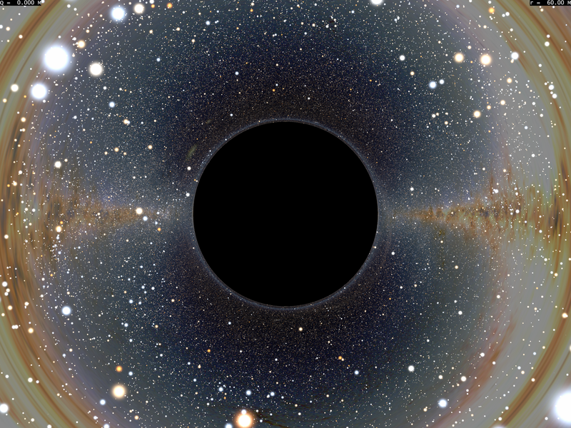
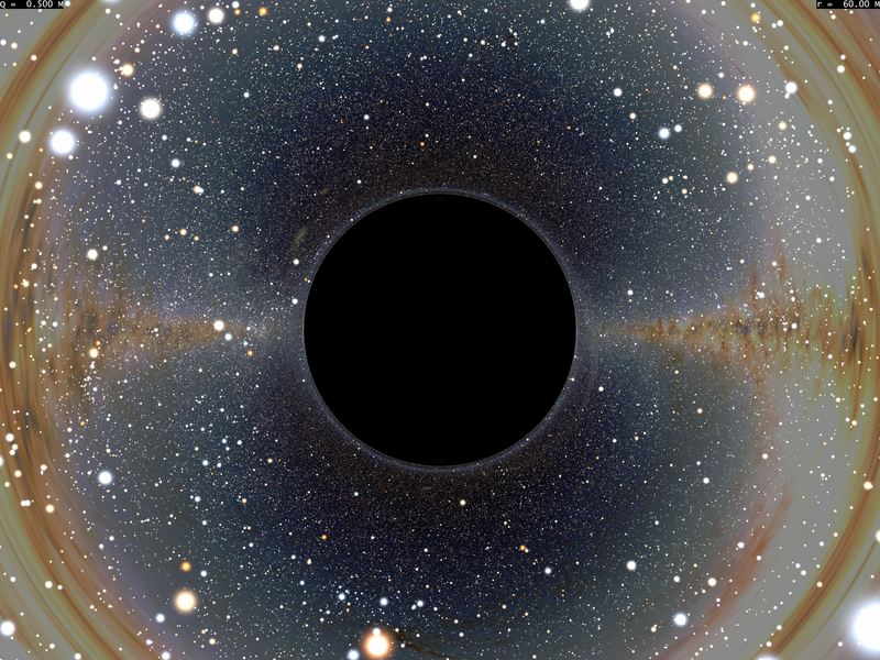
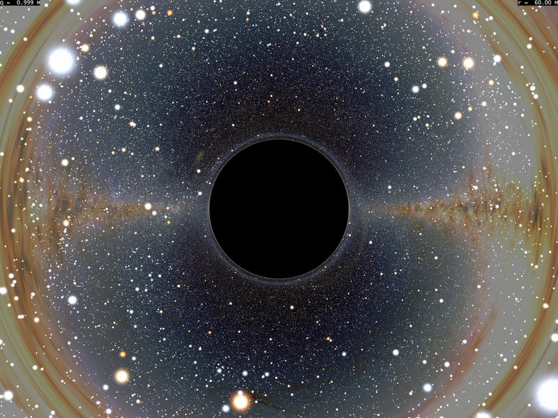
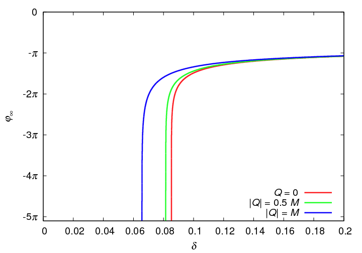
The reason for this qualitative similarity comes from two facts we shall explain:
-
1.
There exists a critical value of the impact parameter under which a null geodesic crosses the horizon;
-
2.
The deviation function diverges as the impact factor reaches the critical value.
The first point above is a direct consequence that, just in the Schwarzschild case, the effective potential experienced by null geodesics, , exhibits a local maximum for some larger than the outer horizon. This maximum, which is at , is shifted to in this Reissner-Nordström case. Moreover, the corresponding extremal value of the effective potential, which was in the Schwarzschild case, is shifted to
| (24) |
which can be rewritten in several way using the fact that satisfies Eq. (8).
Among the null geodesics starting from infinity those that delineate the silhouette of the black hole are those whose impact parameter is given by
| (25) |
where for the last equality we have used the fact that is solution of Eq. (8). Since the function is monotonous increasing for , is an increasing function of (since its smallest value is ), and is therefore a decreasing function of . Its maximum value is for the Schwarzschild case. It decreases to for the extremal case and further to for the largest value of for which it is defined. This is shown in second panel of Fig. 1. The fact that decreases as increases means that a charged black hole angular diameter appears smaller in the charged case than in the uncharged one, although this decrease is not proportional to the black hole coordinate radius .
As for the second point, the divergence of the deviation experienced by null geodesics of impact parameter arises from the fact that the variation of the azimuthal angle of the geodesic with respect to the radial coordinate is given by the well-known results (here adapted of the Reissner-Nordström case),
| (26) |
In the neighbourhood of , the term in the square root can be expanded as , so that the integral diverges logarithmically. On the other hand, null geodesics with impact parameter close to , one can expand the above equation in the vicinity of the turning point that we shall note
| (27) |
The integral of the expression no longer diverges, and is proportional to . The first term of this expression is bounded by and hence finite, but the second one can be made as small as possible, thus allowing for an arbitrarily large deviation, which completes the proof.
These two properties are not very interesting since they already existed in the Schwarzschild metric. Things becomes more interesting either when one crosses the horizon (because one becomes sensitive to the inner part of the metric which very different from the Schwarzschild case), or when there is no horizon at all. It is on this last case that we shall focus now.
V Looking at a naked singularity
When , there are no horizons and the singularity is naked. However, this singularity is pointlike, and among null geodesics only radial ones can originate from it. Consequently, the naked singularity occupies only one pixel of the celestial sphere, whose spectral properties are unknown since they arise in principle from some quantum theory of gravity. We shall therefore ignore them and assume that no photons emerge from this singularity.
If or if then all null non radial geodesics crossing the observer’s worldline originate from null infinity and end at null infinity. Consequently, the whole field of view, up to the pixel corresponding to the singularity, shows the background celestial sphere. In the other case, there are bound geodesics (see Table 1) which, assuming that no photon fill any of those geodesics, will appear as a dark, spherical shell (since the metric is spherically symmetric) surrounding the singularity (see next Section).
V.1 Distortion of the celestial sphere
Regarding the deformation of the celestial sphere, the deviation function is plotted at the bottom of Fig. 4. Contrarily to the Schwarzschild case, it shows a maximum for some value of since any null geodesic hits the effective potential when its first derivative is non zero, which implies that deviation is always finite. Moreover, the deviation decays to a finite value () for .
These two features induce several differences with respect to the Schwarzschild metric. Firstly, because the deviation function does not diverge, there is only a finite number of multiple images of a given background object. Secondly, because the deviation function derivative cancels at the maximum of deviation, the background image distortion will produce radial shear rather than tangential shear one is used to observe at an Einstein ring. Because of the spherical symmetry of the metric, this radial shear region will lie along a circle surrounding the singularity. Thirdly, along this radial shear phenomenon, a set of two multiple images of a given object will exist inside and outside the radial shear ring. When the amount of maximum deviation varies, for example when the observer’s distance changes with respect to the black hole, these images appear of disappear by pairs. In Figure 3, we show three realizations of a naked singularity for increasing values of , together with the corresponding deviation functions.
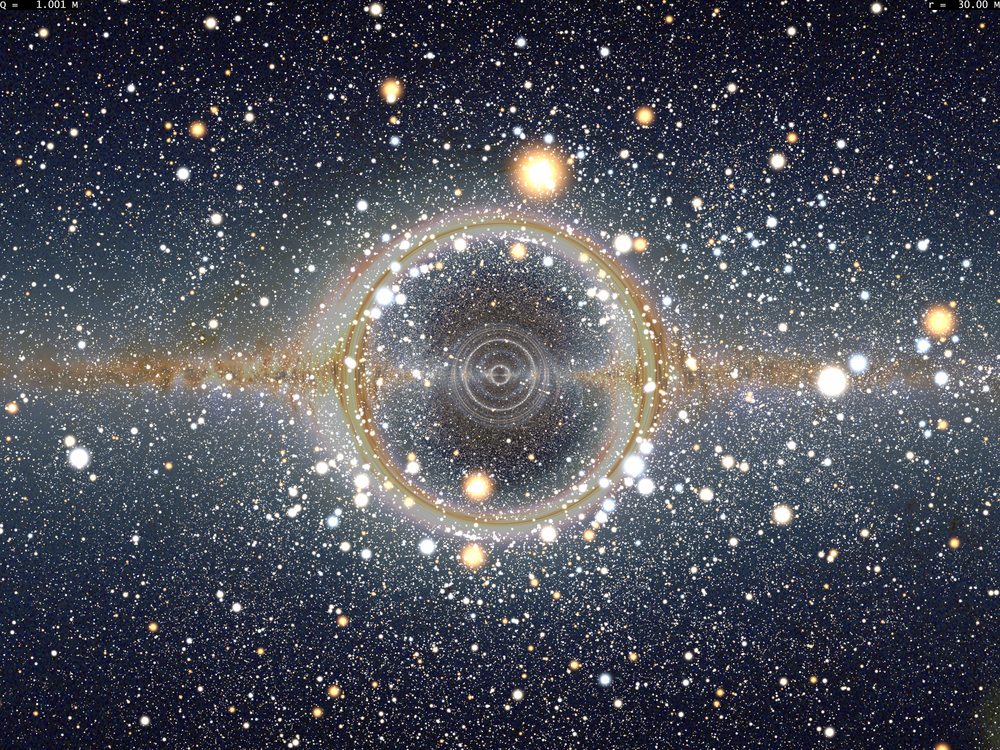
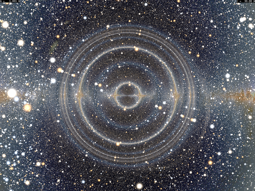
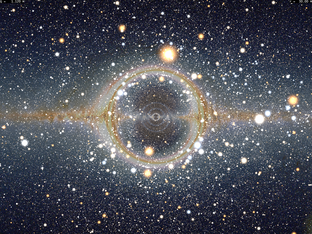
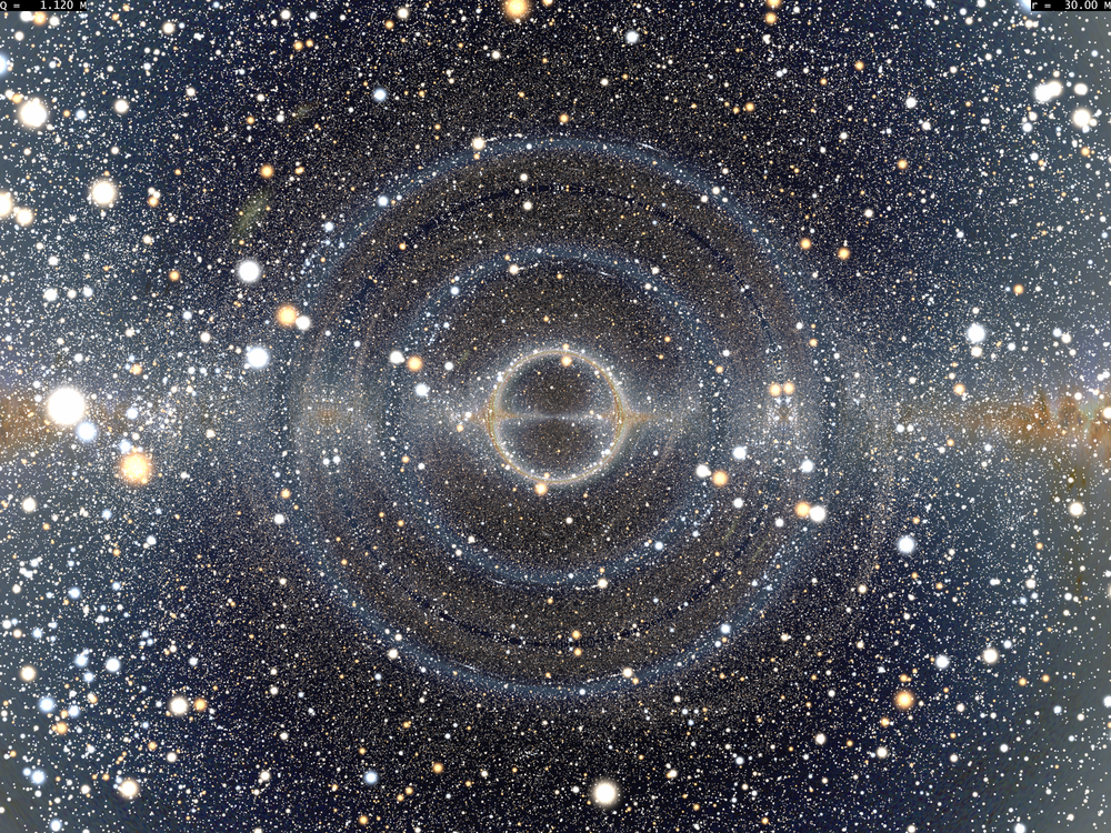
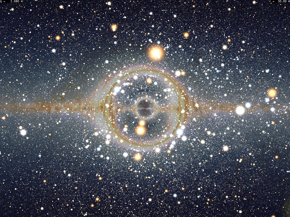
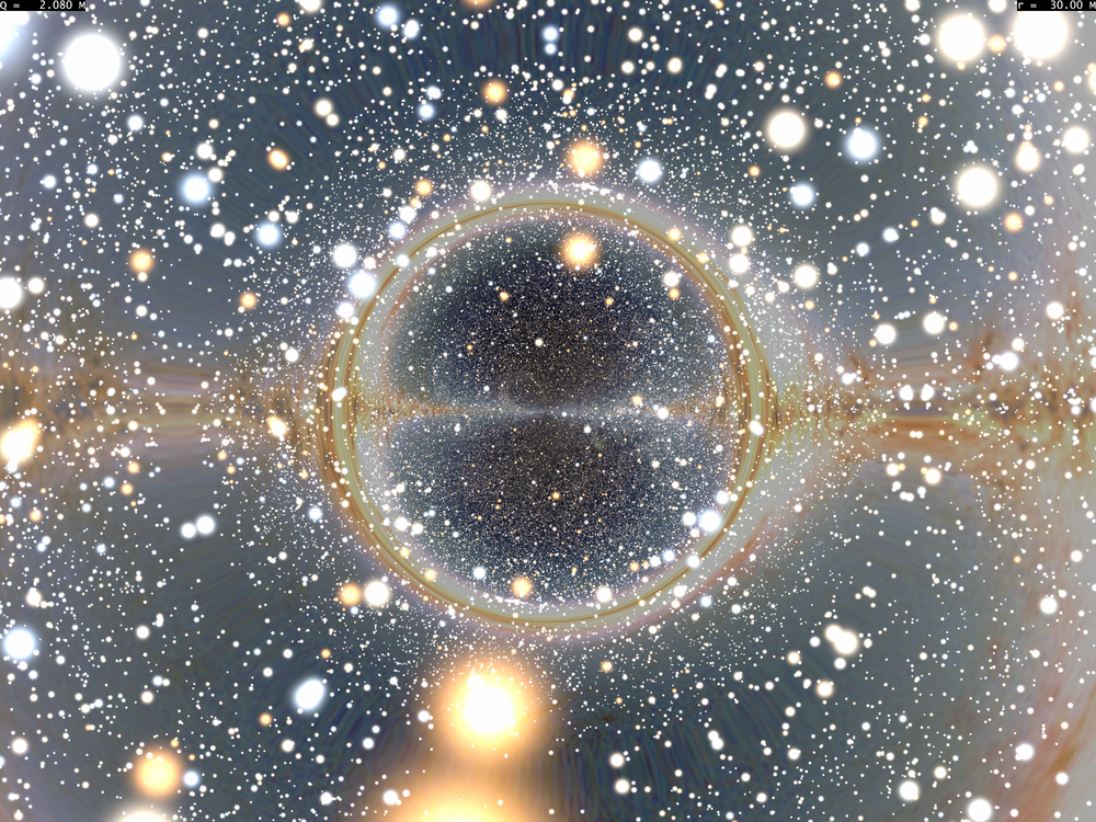


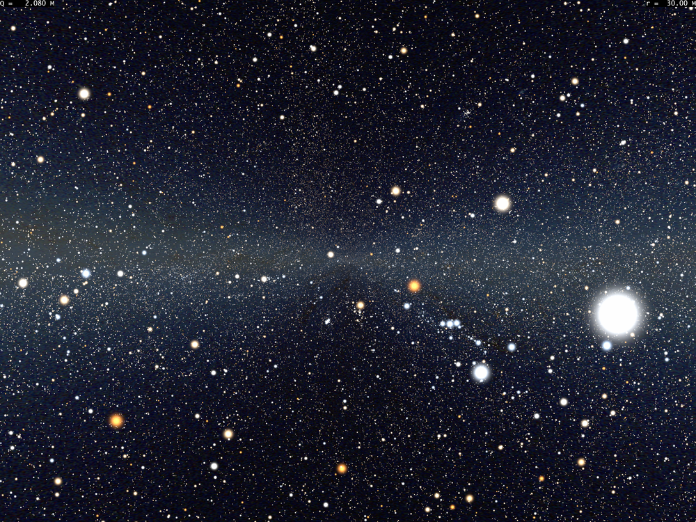
An interesting feature of the deflection function is that whatever the value of it tends to 0 as tends to 0. This means that what is seen when looking toward the singularity is actually what is exactly behind the observer. In other words, if one looks toward the Galactic center with a naked singularity in between, then one shall see the Galactic anticenter close to the singularity, as shown in Fig. 5.
This effect is somewhat counter intuitive, for a radial, null geodesic going toward the singularity will reach it. But apart from those exactly radial geodesics, any other which exhibits a slight deviation from the purely radial case will bounce and go back (almost) in the opposite direction it was travelling prior to the bounce.
This can be understood as follows. When the impact parameter is very small, Eq. (6) can be approximately rewritten by saying that everywhere it is defined, that is, for any where is the turning point of the trajectory. Consequently, the total deviation experienced by such geodesic can be rewritten
| (28) |
(We assume that the observer sits at infinity. Dropping this assumption does not change the conclusions.) The value of this expression is obviously,
| (29) |
Now, in the limit where the impact parameter is small, the turning point of the trajectory occurs when which can occur only at very low values of since must be very large. In this case, is well approximated by the leading term in , so that one has and the deviation of the geodesic is therefore of order
| (30) |
which means that it is very small. Very roughly speaking, this amounts to say that the vicinity of the singularity acts as a spherical mirror on which geodesics are reflected back, except for those which are exactly radial. This analogy, although crude, allows to understand that the view of the celestial sphere shown by these geodesics will be flipped, as also shown on Fig. 5. Also, Fig. 4 show that even for large value of , the deviation function changes rather abruptly around , which means that geodesics with similar, almost 0 impact parameter will be deflected by a significantly different amount. This translates into the fact that a small beam of geodesics reaching the observer after having traveled in the immediate vicinity of the singularity come from a larger patch of the celestial sphere, which shall therefore appear elongated along the radial direction from the point of view of the observer, a feature also obvious in Fig. 5.
V.2 Frequency shift close to the singularity
Since the metric of a naked singularity is everywhere static, it is natural to consider static observers as well. At large distances (where the is negligible in the metric (1, 2), such observers are in a weak potential well and therefore see any radiation coming from past null infinity with a weak blueshift, similarly to the Schwarzschild case, but the situation changes when one is near the singularity. The reason goes as follows. A photon whose frequency is as seen by a static observer far from the singularity has a four-wavevector whose time component is therefore (so that is a constant that reduces to ). Consequently a static observer catching this photon will measure a frequency given by
| (31) |
Sufficiently far from the singularity, is close to 1, although slightly smaller, consequently a weak gravitational blueshift is observed as we just said. Conversely, very near to the singularity, is larger than 1 and the whole celestial sphere seen by a static observer would appear redshifted redshifted, as shown in Fig. 6, the redshift being
| (32) |
which correspond to in Fig 6.
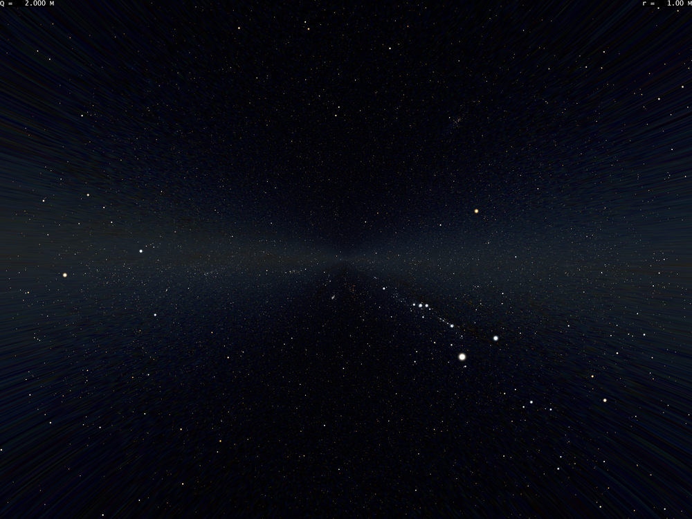
In the limit where the observer is arbitrarily close to the singularity, the celestial sphere redshift tends to infinity, a mere consequence of the fact that in this case the observer lies on a very high potential hill. As for what the observer would see if one could neglect redshift, it would correspond to a tiny portion of the celestial sphere. The reason is that only null geodesics with a small impact factor can reach very small values of before bouncing on the singularity. But those geodesics experience only a weak deviation, so that only the part of the celestial sphere that is situated in a narrow beam centered on the half-line joining the singularity and the observer can be seen.
VI The “dark shell” phenomenon
Since there exists bounded null trajectories, an observer lying within the region where such trajectories extend into will see nothing when looking toward the directions they propagate. Of course, when a horizon exists, those trajectory can be mistaken by the horizon itself. But such trajectories also exists when there is no horizon, for a moderate range of , i.e., when . For a static observer, those bound null geodesics will be seen around the perpendicular direction with respect to the radial one, giving an overall aspect of a thin, dark shell surrounding the singularity, which appears in front of a fairly bright (i.e., blueshifted) background of stars. The reason why the stars are blueshifted goes as follows. The frequency shift between radiation seen by a static observer at infinity and a static observer near to the singularity is given by . It then suffices that is smaller than for the radiation to be blueshifted, which can be shown rather easily. Solving gives , which we label this way since it corresponds to the minimal coordinate distance a freely falling observer would reach. For any , one has . Moreover, we have , whose minimum value when is , which is always larger than . Consequently, is situated at some smaller value than and the celestial sphere is blueshifted.
More quantitatively, the minimal value of is obtained for . Given the interval where is allowed here, this value of does not exceed , which is smaller than the smallest value of , therefore . Since is a decreasing function for and a decreasing one otherwise, the largest value of within the interval is either or A, but the fact that by definition means that , therefore the maximal value of in the above mentioned interval is , whose value can be written, using Eq. (8),
| (33) |
The first formula ensures that as soon as since then, the smallest value of is , which means that the frequency shift seen by a static observer within the dark shell region is at least . As for the maximal frequency shift, it is obtained when is close to , which occurs in the limiting case of an extremal black hole with an observer close to .
We now come to the thickness of this shell seen from a static observer. From a static observer, one can attach a reference tetrad with one vector corresponding to the observer four-velocity, , i.e., the vector defined in Eq. (15), one to an orthonormal vector spanned by , i.e., the vector defined in Eq. (20), , and two normal vectors spanned by and , and . By suitably choosing an orientation of the coordinate system, a null geodesic is of the form
| (34) |
From this geodesic, one can compute the constant of motion and similarly to Eqns. (22, 23). A null geodesic participates to the dark shell phenomenon if it is bound, i.e., if and if its effective energy is smaller than the local extremum of . This amounts to says that
| (35) |
which translates into
| (36) |
The dark shell is at its widest when is at its smallest value within the range of one considers, i.e., at . The dark shell maximal angular width is therefore
| (37) |
In the extremal case one has so that . Therefore, and the dark shell occupies all the celestial sphere, however no static observer can lie at besides an extremal black hole. Should one take instead of (or, alternatively, ), with , then the dark shell would have a width close to but smaller than and would fill almost but not all the celestial sphere. The maximal dark shell width seen by a static observer is shown in Fig. 7. Its width as a function of both and is plotted in the same Figure.


A similar phenomenon arises when but it is then less spectacular since there is no distinction between the dark shell itself (i.e. bound null geodesics in the sense described above) and other, unbound, geodesics that also cross the black hole past horizon. The only way to differentiate the two is to consider the maximal analytic extension of the metric, something we shall consider in next Section.
Let us add that the width of the shell of course depends on the observer’s velocity. Should one consider a freely falling observer along a radial trajectory, then aberration will push and shrink the shell toward the singularity. Also, the freely falling observer induces a large redshift and blueshift with respect to the static case which can be computed as follows. The Lorentz boost to go from a static observer with four-velocity to a freely falling observer with four-velocity is given by
| (38) |
the relative velocity between the two frame being therefore . If we suppose light rays coming from infinity along an almost radial ingoing or outgoing trajectory, their corresponding four-wavevector components are
| (39) |
where is the light ray frequency measured by an observer at infinity. The frequency measured by a freely falling observer is then
| (40) |
Using the notations and defined above, we have
| (41) |
This formula differs from the special relativistic formula of redshift by a factor , which corresponds to the extra contribution of gravitational blueshift experienced when within a potential well. It is then easy to show that this quantity reaches its extrema whichever the sign is when does, i.e. at . Then, one has , which implies that . The maximum blueshift can therefore be fairly large and even tends to infinity when .
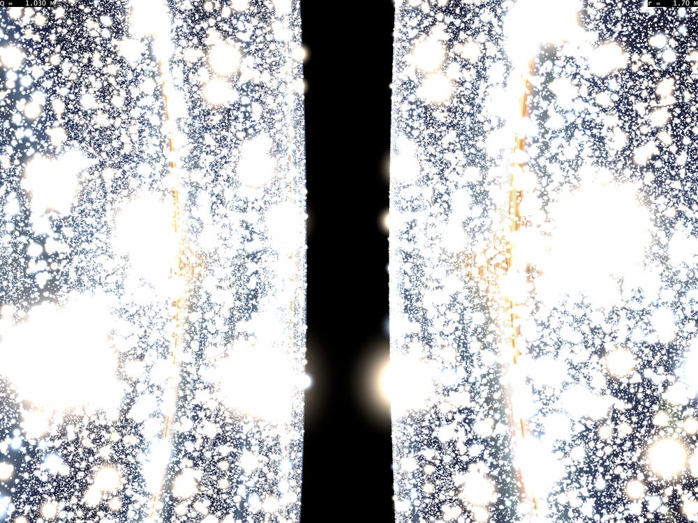
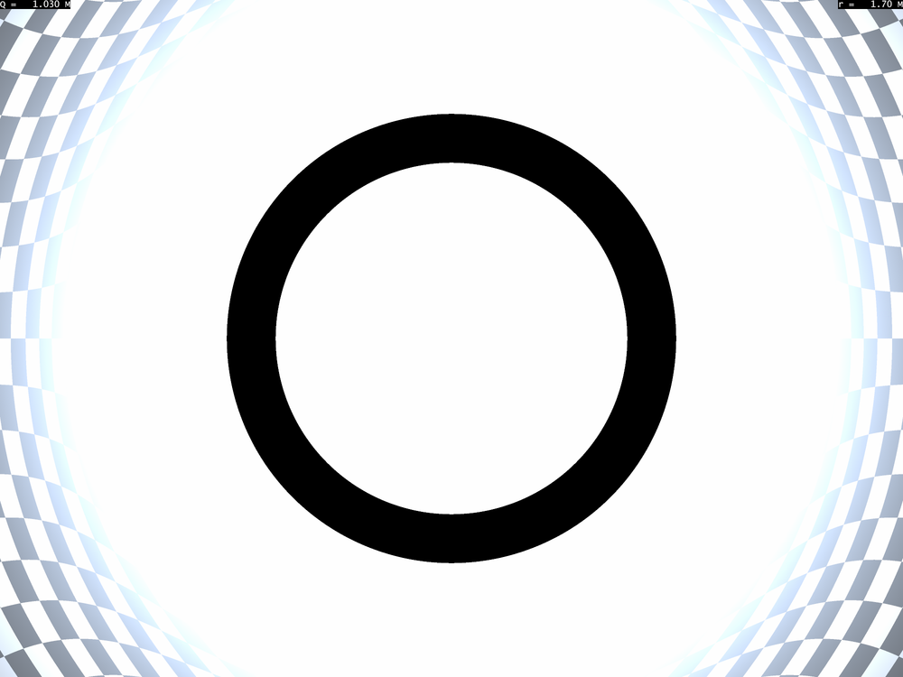
Regarding the shell angular width, it has then has a fairly cumbersome form and is always smaller than in the static case because of aberration. In Fig. 8, we show how the dark shell aspect transforms when one goes from a static observer to a freely falling observer with zero velocity at infinity.
VII Looking at and crossing a Reissner-Nordström wormhole
The maximal analytic extension of the Reissner-Nordström metric possesses an infinite tower of pairs of asymptotic regions similar to those of the maximal extension of the Schwarzschild metric. Its Carter-Penrose diagram can be described as follows. Regions 1 and 3 (labels are chosen so as to match those the Schwarzschild metric in Ref. riazuelo15 ) are asymptotic regions, with being a spacelike coordinate and being a timelike coordinate, which is future-oriented in 1 and past oriented in 3. The inter-horizon part of the metric, i.e., , in region 1 (or 3) future is labelled 2. There, is a past-oriented timelike coordinate. Similarly to the Schwarzschild case, there exists another such inter-horizon region which is in regions 1 and 3 causal past. Such a region will be labelled 4 so as to follow the Schwarzschild case.
The inner region () part of the metric is split into two regions, 5 and 6, where, as in 1 and 3, is a timelike coordinate and is a spacelike coordinate. We choose to label 5 the region directly above 1 (i.e., to the right of the diagram), and 6 is the one above 3. Obviously, a radial null geodesics that goes through the black hole travels along 1, 2 and 6 since it is by construction a straight line going toward an upper left quadrant. Since is constant along this (or any) geodesics and since is positive in both 1 and 6, has to be positive in 6 as well. Consequently, is a future-oriented timelike coordinate in 6 and similar reasoning with a radial null geodesic starting from 3 shows that is past-oriented in 5. Since is conserved for any geodesic, timelike geodesics will also travel along the 1-2-6 or the 3-2-5 sequence. There, they will bounce at some distance of the singularity, and will follow a symmetric outgoing trajectory. They will first travel along another inter-horizon region where this time is future-oriented. This region is similar to region 4 defined above and will be labelled 10. Then geodesics will exit a new asymptotic region that we shall label 7 (above 5 and 1) and 9 (above 6 and 3). There is therefore an infinite tower whose basic blocks are a series of six regions in the Carter-Penrose diagram as summarized in Fig. 9. Timelike or null geodesics (except in the case of radial null geodesics) originating from past null infinity of regions 1 or 3 will therefore travel along the 1-2-6-10-7 or 3-2-5-10-9 sequence. Also, because the effective potential admits a local minimum, there also exist bound timelike of null geodesics which endlessly cross and exists the numerous horizons of the metric. Those passing in region 1 then have followed the sequence …4-1-2-6-10-7-8-12-16…, when the -th region is deduced from the -th one by adding 6.
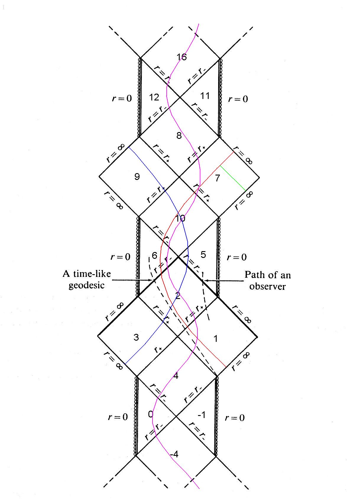
Even though the analysis of the Carter-Penrose diagram allows to know which regions are seen along the wormhole hole crossing (which we shall perform from a radially infalling observer from region 1, thus following the 1-2-6-10-7 sequence, see above), it is not intuitive to guess what such observer will actually see. Also it is not much easier to guess how region -5 might look as seen from region 1, even when far from the wormhole.
We shall therefore address this first issue, and then address the whole problem of what is seen not only outside a wormhole, but when traveling through it.
VII.1 Orbiting around a wormhole
Outside a Reissner-Nordström wormhole the metric is the same as in the black hole case and therefore allows for circular timelike geodesics, at least as long as is not too close to the horizon. It is therefore legitimate to consider the view seen from a timelike circular orbit.
We start from the view seen by a static observer. The deviation function is shown in Fig. 10.
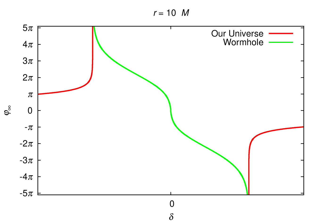
The external part of the deviation function is unsurprising since it correspond to that one sees in a standard black hole case and it diverges for an angular separation which corresponds to the critical impact parameter. The other region is seen through outgoing null geodesics which have an impact parameter smaller than the critical one. Close to the edge of the wormhole, the impact parameter is vanishingly close than the critical one and geodesics experience a diverging deviation. Close to the geometric center of the wormhole, geodesics bounced on the central region of the wormhole before exiting it, just as in the white hole case. Consequently, one expects that the deviation function is decreasing from to when looking from left to right at the wormhole throat. Such a feature implies that any part of the region seen though the wormhole throat will be seen an infinite number of time and that a double series of Einstein ring shall outline the region on the other side of the wormhole directly ahead of the observer and that on the opposite side.
Looking at Fig. 10, it is clear that the angular intervals where the deviation function is not very step are somewhat extended. This will translate into the fact that the angular distance between the Einstein rings will not be small as it is the case for the (outer part of the) Schwarzschild solution, which means that several Einstein rings will be rather easy to spot as concentric, circular regions with sparse but bright stars because of gravitational lensing. A star that appears lensed in one Einstein ring will also appear as such in the other associated rings. Since Einstein rings alternate between what can be dubbed as the rear direction (i.e., trajectory very close to the center of the wormhole) and the opposite one, a given lensed star will be seen every two Einstein rings.
Moreover, since the deviation function is zero of radial trajectories, the center of the image seen through the wormhole does not correspond to deflected photons passing through the wormhole, but to photon that bounced at some distance of the singularity. In other words, whereas a Morris-Thorne wormhole does not show significant amount of distortion in the center of its silhouette, a Reissner-Nordstrom wormhole does, and it is difficult to recognize anything whose image has traveled through the wormhole as this image will always appear distorted. An example of this, with the Milky Way seen through the wormhole given be shown in Fig. 25.
Including the observer’s circular motion introduces two extra features (that are also present in the standard Schwarzschild black hole case, but at a lesser extent because of the visual structure of Einstein rings). Firstly, lens images of stars will no longer be aligned as aberration will transform great circles into circles. Secondly, Doppler shift will affect both color and magnitude of stars. Such features do not prevent from identifying lensed star image alignments, however, as shown in Fig. 11.
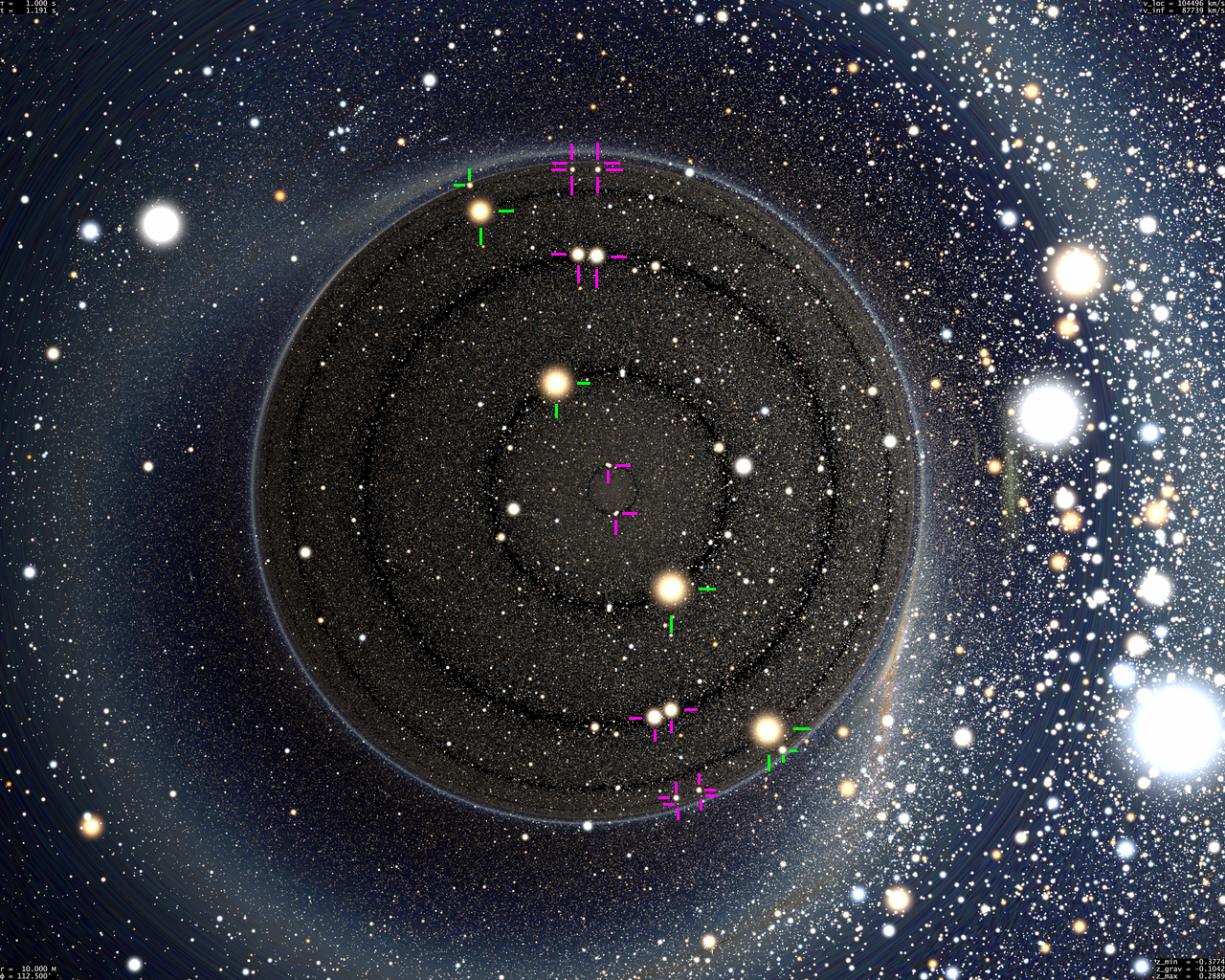
Numerous Einstein rings are visible within the wormhole, which alternatively zoom in on the region that lies somehow behind the singularity from observer’s point of view and the opposite region. They are easily spotted as circular thin shells devoid of stars (regardless of aberration which transforms circles into circles). One bright star and its multiple images are outlined with green segments. There are two images per Einstein rings, on each even ring when counted from the center. Seen by a static observer, all these images would lie on a straight line, which is transformed into a circle by aberration. Four bright images of the star are seen, plus two fainter ones very close to the edge of the wormhole. We have also shown with purple segments the multiple images of a pair of stars on odd-numbered circles. Eight images of these stars can be seen, although the outermost ones are barely visible. Many other multiple images of stars within the wormhole can be seen.
VII.2 Crossing the wormhole – Infalling part
When one lies outside the wormhole, its angular size varies in a similar fashion as in the Schwarzschild case, but the combination of special and general relativistic effects make it complicated to interpret. In Refs. riazuelo15 , some counterpointed aspects were detailed, such as the fact that a static observer close to by outside a Schwarzschild black hole will have the visual impression to actually be inside the black hole, whereas on the contrary, an infalling observer soon after horizon crossing will be tempted to think that he/she is still outside. Considering that the maximal analytic extension of the metric adds some extra layers that can be seen by an observer, e.g., dark shell and other asymptotic regions, it is very difficult to guess how a wormhole crossing would be visually felt by an observer. Furthermore, the simplest wormhole one may think of, the Morris-Thorne wormhole morris88 , possesses only two regions, the entrance and the exit of the wormhole, so that wormhole crossing is not spectacular as no intermediate region is actually visible james15 .
This motivates the study of a more complicated wormhole crossing such as the RN wormhole. In practice, the most obvious visual features of some landscape are the large-scale ones, so that we shall here first address the problem of the angular size of each regions that are seen by the observer. We shall split this problem into two steps, the infalling part (this subsection), where the observer starts from infinity, crosses the outer then the inner horizons, and bounces at (see discussion after Eq. (16)). The outgoing part of the travel will be described in the following subsection.
VII.2.1 Size of region 1
The edge of the observer’s initial region, 1, is delineated by null geodesics of impact parameter . Let us consider an observer of four-velocity (see Eq. (17)). Given the definitions of the constants of motion and (see Eqns. (22, 23)), one can write the impact parameter of a geodesic making and angle with respect to the radial outgoing direction. This gives
| (42) |
Writing that a null geodesic with impact parameter is making an angle with respect to the radial direction is therefore equivalent to
| (43) |
where we have introduced the simplifying notations
| (44) |
Moreover, we shall consider only the case where since the negative values of are expected to give the same results, up to change the sign of .
We now have to solve this equation, taking into the fact that it must also satisfy the following criteria:
-
1.
The geodesic must originate from region 1, where is a future-oriented time coordinate, which amounts to impose that
-
2.
In order to delineate the edge of the wormhole, it must have reached the value (where it experienced an arbitrarily large deviation) prior to reaching the observer. This amounts to say that the geodesic must be outgoing for and ingoing for
-
3.
A last tweak must be taken into account when the observer reaches region 6. In this case, both ingoing and outgoing geodesics do delineate the edge of region 6.
Forgetting about the last point above, the general solution of the equation is given by (see Ref. riazuelo15 for the derivation):
| (45) |
where we have set
| (46) |
and we have made use of the two equalities
| (47) |
which result from Eqns. (8,25). This angle corresponds to the silhouette of the black hole, since any value of larger than obviously correspond to geodesics that can reach the observer after originating from past null infinity. At large distances, this expression reduces to , as expected from an object of cross section . Also, the angular size of the wormhole increases (albeit slowly) as the distance to the horizon decreases.
One can also evaluate this expression at outer horizon crossing, i.e. when the observer actually enters into the black hole (or, in this context, the wormhole, but it does not matter here). One obtains
| (48) |
a formula which has the same form as that of the Schwarzschild case (see Refs. muller08 ; riazuelo15 ). The quantity is a decreasing function of , which means that, just as for a static, distant observer (see Fig. 2), a charged black hole has a smaller angular diameter with respect to an uncharged one when a freely falling observer enter into it. It angular diameter varies from for the Schwarzschild case to for the extremal case. The angular size as a function of the charge-to-mass ratio is shown in Figure 12. Incidentally, a similar formula holds for inner horizon crossing, i.e.,
| (49) |
which immediately shows that the wormhole or black hole angular size begins to shrink at some point as the radial coordinate decreases. We did not however find any analytic expression of the value of for which the angular size reaches its maximum.

In fact, solution (45) is only defined for since the square root of the denominator can be rewritten as
| (50) |
For values of smaller than , there is no solution to Eq. (43) which means that region 1 fills the whole celestial sphere although no geodesics with impact factor as large as reach such low values of . This is because a null geodesic turning point is determined by equation .
In the rather small interval , one must consider both ingoing and outgoing solutions of Eq. (43). This ingoing solution has been expressed above, and the outgoing one amounts to change the sign in front of the square root of the numerator, which gives
| (51) |
This solution goes to at and catches at . Its interpretation is that during most of the infalling phase, region 1 does not appear when one looks exactly in the center of the wormhole. When far from it, one sees region -5 in this direction, and when that region disappears at outer horizon crossing, it is replaced by region 3. It is only when one crosses the inner horizon that the observer can see (almost) radial null geodesics from region 1 that have already bounced close to the singularity and that now travel outward. Such geodesics to the not belong to the same region as those that made the main image of region 1 which are all ingoing once outer horizon has been crossed. This second copy of region 1 first appears as a dot at inner horizon crossing and further grows so as to touch the other, main, view of region 1 (seen along directions ) when the observer reaches . Then, only a single copy of region 1 is seen filling the whole celestial sphere, although is it still made of two types of geodesics: those that are ingoing and which show a distorted but unflipped view of region 1 and those that are outgoing and which show a flipped view of region 1 for the same reasons that were explained in the naked singularity case (§V).
VII.2.2 Size of region 3
A similar reasoning allows to compute the angular radius, of region 3, which becomes visible in region 2, between the two horizons. The only difference is that in this case, the coordinate is past-oriented in region 3, which implies that the constant of motion is negative. This amounts to change the sign of the numerator in Eq. (43). The result is then
| (52) |
(Again, the derivation is adapted from the Schwarzschild case whose derivation is given in Ref. riazuelo15 .) This time, region 3 corresponds to geodesics endowed with an angle . The second formula shows that is defined (i.e., again, is positive) only when is negative, which means that . This means that region is visible only from region 2. Also, and goes to at those two values and close to those, one has
| (53) |
Seen as a function of coordinate distance , the angular size of this region shrinks faster as the observer gets near the inner horizon than it had grown soon after outer horizon crossing. This is also true in term of the observer’s proper time since for the observers we are considering, one has , so that takes the same value (i.e., ) at both horizon crossings.
VII.2.3 Size of region -5
The last bit of solution one might be interested in are geodesics from region -5. The derivation is the same as for region 1, except that all these geodesics have bounced in the inner horizon region, which means that they are always outgoing, regardless is larger or smaller than . The solution for these geodesics is then, after a few manipulations,
| (54) |
It is unsurprisingly the same formula as for since there is no dark shell for those values of , so that images of region -5 and 1 touch each others. The two formulae differ for smaller values of as expected from the fact that the dark shell phenomenon exists. For , there are no solutions to this equation, which means that region -5 ceases to be visible when the observer crosses the outer horizon, again as expected from the Carter-Penrose diagram.
VII.3 Crossing the wormhole – Outgoing part
When considering an outgoing observer, the above procedure is still valid, except that in the definition of , we must consider an outgoing observer, i.e., with a four-velocity , which amounts to change the sign in front of the square root of Eq. (43). Moreover, any almost radial null geodesic coming from region 1 will bounce before reaching the singularity and will eventually intersect the observer’s worldline. Therefore, directions close to the ingoing radial direction will still show region 1, and region 3 shall appear in the opposite direction when reaching region 10. When leaving region 10, region 3 will disappear forever and will be replaced by the new region the observer’s journey ends to, region 7. In order to compute angular size of all the observable regions, we now need to consider an observer with velocity . The same machinery as before can be used, and the simplest region to study is region 3. Taking care of all the signs, one obtains that it is delineated by angle given by
| (55) |
It is rather straightforward to check that (for this purpose, one needs, again to use Eqns. (47)), so that we have the very simple result
| (56) |
In other words, when the outgoing observer lies between the two horizons, region 3 appears not only at the opposite side but also with the same angular size as it had for the same value of during the ingoing phase. This result is valid for an observer whose initial velocity is and who further follows a geodesic. However, this is also true for any observer who follows any geodesic, whether it is radial or not, or that it reaches infinity or not. Indeed, considering another freely-falling observer with a different initial velocity, he/she will have, when entering region 2, a different view of region 3 because of aberration. However, once this second observer will bounce back in region 6 and enter region 10, thus seeing again region 3, the second observer’s relative velocity with respect to the first one will be exactly the same as in the infalling phase, because in both case, the two observer’s velocity differ only by changing the sign of their component. Therefore, it is the same Lorentz transform that allows to go from the first to the second observer’s velocity during the infalling and outgoing phase, for a given . Therefore, at given , region 3 will have the same size for any observer following a geodesic during the ingoing and outgoing phases.
Regarding region 7, we have to solve Eq. (43), after having flipped signs in front of the square roots, by keeping in mind that what delineates region 7 are ingoing null geodesics as long as and outgoing null geodesics afterwards. After a few manipulations, one obtains
| (57) |
whose positive values are, as expected, defined only for . As for , the expression tends toward at large .
The last bit of solution corresponds of what one sees of region 1 during the outgoing phases. When the observer is in region 6, the most deflected null geodesics coming from region 1 are those that are outgoing, and therefore delineate the edge of this region. Moreover, as soon as the observer leaves region 6, all null geodesics that reach him/her are outgoing, therefore it is those geodesics, with impact parameter , that need to be taken into account. Solving for the last time Eq. (43) finally gives, for ,
| (58) |
This solution is identical to that of for since in that case, the dark shell phenomenon no longer arise and images of regions 1 and 7 touch each other (this is the same reasoning we outlined for regions -5 and 1 during the ingoing phase). For smaller values of , they differ because of the dark shell phenomenon, however, in this region we have, just as in the case of region 3,
| (59) |
so that
| (60) |
This means that the angular size of region 1 is identical in the ingoing and outgoing phases, as long as region 1 and region 7 do not touch each others. The first part of this result can be shown exactly as we did for region 3. Regarding the last part, the fact that region 1, and, hence, wormhole angular size does not match between the infalling and outgoing phases is a mere consequence of the fact that in both case a static observer would see the same thing, but here ingoing and outgoing observers see of modified angular size with respect to the static case because of aberration.
All these results can be summarized in Fig. 13 for the ingoing phase and Fig. 14 for the outgoing one.


VII.4 Computing redshifts
The other quantity of importance is the redshift or blueshift of the radiation as a function of the direction. From Eq. (23), the constant of motion of a photon starting from past null infinity of region 1 or 7 is nothing more than the initial angular frequency, of the corresponding wave. Therefore, the frequency shift of the wave is given by
| (61) |
where corresponds to the ingoing phase of the wormhole crossing, and to the outgoing one. When considering photons coming from region 3, then, because is a past-oriented timelike coordinate in region 3, the constant of motion corresponds to the opposite of the angular frequency. Therefore, the frequency shift of photons coming from region 3 is
| (62) |
with the same value for as above.
Several features can be seen from these two formulae:
-
•
One sees immediately that for each event of the wormhole crossing, the frequency shift is always equal to 1 in any direction perpendicular to the radial one, a result that matches Newtonian physics, but not special relativity.
-
•
From the first equation, we see that the radial null geodesics that catch the observer “from behind” () are, as can be guessed intuitively, redshifted, by a factor equal to . The redshift is negligible at large distance since the observer velocity with respect to distant sources is weak and so is the gravitation blueshift. Then, the redshift reaches when entering the outer horizon (since there, so that ), increases further till the minimum negative value of which occurs at , for which the redshift is . It then decreases to at inner horizon crossing and reaches 0 when the observer bounces at . Once the observer is in his/her outgoing phase, radiation catching him/her from behind (which, this time, correspond to ) is observed at a redshift which follows the same variation, so that once the observer exits and goes far from the wormhole, region 1 is seen without significant redshift.
-
•
The case of radiation coming from region 1 seen by the observer in front of him/her is more interesting. During the ingoing phase, there may by some radiation seen by the observer from direction , which sits in the middle of the wormhole silhouette; if one assumes that radiation comes from region -5. In this case111Strictly speaking such geodesics do not exist in the sense that pure radial null geodesics coming from region -5 or, later, region 1, hit the singularity rather than bouncing on it, however, null geodesics with a vanishingly small impact parameter can be seen. We shall therefore consider that geodesics are seen toward the direction., the radiation is blueshifted and reaches an infinite blueshift as region -5 disappears, when the observer crosses the outer horizon. At this instant, the observer sees radiation from region 3 which first appears infinitely blueshifted as well, but further, the blueshift decreases as the observer travels along region 2. The frequency shift reaches its minimum value at , and is equal to ; which corresponds to either a redshift or a blueshift, depending on whether is below of above . Further, the frequency shift diverges again when the observer reaches the inner horizon. Then, the flipped copy of region 1 appears with an infinite blueshift in its center, and the frequency shift decreases rather abruptly since, when the observer approaches the bouncing point at , it goes to and no blueshift or redshift is seen in any direction.
-
•
The outgoing phase give the same results are before except that they occur in opposite () direction.
-
•
One may wonder whether there are some other sets of which show infinite blueshift, at horizon crossing toward in the ingoing phase and in the outgoing phase, but this is not case. Indeed, such infinite blueshift would occur when , a situation that can only occur when , that is, when is negative, i.e., between the two horizons, in regions 2 and 10. Further, solving the equation in term of gives the same second order equation as in Eq. (43) except that the term in front of is zero, which ensures that the curves never cross any of the except when in the ingoing phase and in the outgoing phase, so that the curve is either entirely in region 1, or entirely in region 3 or in the dark shell region. It then suffices to compute all the ’s for a single value of (the simplest ones being and ) to show that the curve of infinite blueshift lies in the dark shell region, so that no infinite blueshift are seen, except, as we said, at the disappearance and appearance of regions -5, 1, 3 and 7 at either or .
The maximum and minimum frequency shift of each region observable during wormhole crossing is shown in Figures 15 and 16.


A natural question that arises is which of the fluxes from these regions (except when then actually diverge) is the strongest, at some small but finite coordinate distance from the horizons. In this respect, region 1 differs from all the others by the fact that all the latter exhibit an infinite blueshift at horizon crossing in the same time they have a vanishingly small angular size, whereas region 1 has a macroscopic angular size at inner horizon crossing, which suggests that the overall flux received from it will be larger. Also, angular size of region 3 does not vary at the same rate at inner and outer horizon crossings, so that its flux at should differ from that at . A crude estimate of these two results can be performed as follows.
Close to horizon crossings, the frequency shift of radiation coming from any of the region visible from a direction close to is given by
| (63) | |||||
| (64) |
The total fluxes coming from regions 1 or 3 is given by the fourth power of the above equation integrated on the total angular area of the corresponding region. Since Eq. (63) is large only when , the total flux is of order
| (65) |
The same reasoning holds for region 3, except that the integral is now limited by the actual angular size of this region, which is obtained by expanding Eq. (52), which gives
| (66) |
where corresponds to either , depending on whether one consider inner or outer horizon. Consequently, the flux from region 3 is proportional to
| (67) |
Further expanding close to , gives
| (68) |
so that the ratio between the two fluxes from region 3 at outer and inner horizon crossing is
| (69) |
a result that is in fact qualitatively opposite to the naive expectation for the angular size of region 3 in both cases.
Regarding region -5 and region 3 at outer horizon crossing, the angular size vary in the same way, so that their fluxes diverge in a very similar way.
The last case of interest is how the flux from region 1 behaves close to inner horizon crossing with respect to that of region 3. Using all the results above, we have
| (70) |
so that the flux from region 1 just after inner horizon crossing is much larger than that of region 3 just before. It is then possible to compute for which interval of (or, equivalently, ), this holds, and it happens that it corresponds to . Indeed, as we already said, and are very close to each other, as can be seen by expanding both and as a function of . This gives
| (71) | |||||
| (72) |
The two quantities differ only at the level, and even then, by a narrow amount since their respective coefficients differ by , that is a difference, a situation that, incidentally, also applies for the terms, whose coefficients are also of similar amplitude ( and , respectively, a difference). Considering leads to
| (73) |
One can simplify further this expression by (somehow crudely) approximating , as well as and by their values at lowest order in , i.e., , and , respectively. One then obtains
| (74) |
This means that after , the flux dissymmetry between before and after inner horizon crossing is weak, although the overall flux is fairly large, as can be seen by computing the maximal (i.e., toward ) frequency shift at , which is given by
| (75) |
Even when is large (i.e., close to 1), the above expression is large. In this limit, one has , and , which gives . The frequency shift in the front direction at is shown in Figure 17.

VII.5 Solving the geodesic equation
An observer starting from region 1 will of course see (i.e., be intersected by null geodesics originating from) region 1, but will also eventually see the region from which null geodesics originate when they exit the past horizon. With our conventions, such region is labelled -5. Depending on whether there is anything in -5, the metric will either appear as in the standard (i.e., black hole type) Reissner-Nordström case when the silhouette delineating of the central part of the metric is perfectly black and where region 1 is distorted, or, alternatively, the same distortion in region 1 but this time a highly distorted view of region -5.
In order to compute this distortion, we have to adapt the set of equations (11–14) to the case where horizons are crossed, i.e., when the function is zero. As well-known, one has to switch to another system of coordinates as the coordinates exhibit a coordinate singularity at horizon crossing. Although the coordinate change is outlined in several textbooks, it is almost never done with sufficient detail to allow a straight implementation, therefore we shall give a more-than-usual detailed derivation of it.
The first step consists into transforming the radial coordinate into the so-called tortoise coordinate so that that line element can be written under the form . Writing leads to
| (76) |
where we have set
| (77) |
We integrate this into
| (78) |
from which one sees that is a growing function of for or , and a decreasing function for . This coordinate system can be made regular around one of the values , (but not both simultaneously) by exponentiating it and performing a careful choice of signs. We therefore define
| (79) | |||||
| (80) | |||||
| (81) | |||||
| (82) |
and we need to choose the values of so as to ensure that coordinate system is regular around and so is around . These signs of course depend on the region one dwells in. After some tinkering, one obtain the values given in Table 2, which insure that in any region where they need to be defined, and are future-oriented null coordinates. These coordinates are only of interest when one is in one region which has one edge in common with the (for ) or (for ) lines, so that it is unnecessary to define, say, and in region 1.
| Region neighbouring | ||
| 1 | 1 | -1 |
| 2 | 1 | 1 |
| 3 | -1 | 1 |
| 4 | -1 | -1 |
| Region neighbouring | ||
| 5 | 1 | -1 |
| 10 | 1 | 1 |
| 6 | -1 | 1 |
| 2 | -1 | -1 |
Most if not all paper which give this coordinate transform do not introduce the time constant in Eqns. (79–82), however it is crucial to do so when one actually solves this set of equations with any standard numerical method. This is because without the adjunction of this constant in the coordinate transform, one usually has, just after performing the coordinate change, a large ratio between and , a situation that very significantly hinders the precision of any numerical methods we have tested for solving this set of equation. In practice, we choose the constant as the value of at the moment we perform the coordinate change.
When one performs the coordinate change, one also must do it with the coordinate derivatives of the geodesics we are interested in. They are written as, by using a dot to denote a derivative with respect to the geodesic affine parameter,
| (83) | |||||
| (84) |
where we have dropped the , subscripts in front of , keeping in mind that they are the same everywhere.
Regarding the inverse transform, the case of is rather easy since one has immediately
| (85) | |||||
| (86) |
One then has
| (87) |
(In this equation as well as the previous ones, we dropped the or sign which must be the same everywhere.) The next step is to notice that the product can be written
| (88) | |||||
| (89) |
(In the first equation, one gets rid of the absolute value of because the sign of the product is the opposite of that of , hence the minus sign in front of the result; the same holds with for the second equation.) None of these equations allow an analytical solution, however, they can be solved by any standard method (Newton-Raphson, etc.). The last step is then
| (90) |
This being set, we need to use the coordinates and to solve the geodesic equation. It is not possible to write these equations in a fully closed form that does not depend on , therefore must be understood as a function of the product , see Eqns. (88,89). Dropping the subscript which, again, are the same everywhere, one has
| (91) | |||||
| (92) | |||||
| (93) | |||||
| (94) |
where we have used the function , which has to be understood as a function of only (and hence ), defined as
| (95) |
its derivative with respect to being expressed under the most compact form
| (96) |
Despite the way they are defined, or are not singular, either when in Eq.(95) or in Eq. (96), because in both cases, their numerator of or is also zero and all the quantities we deal with are continuous here (except of course for the usual coordinate singularity of the spherical coordinates). Indeed, this is exactly this set of equations we solve using some standard integrators press92 without encountering significant issues (except when we made an improper choice of ).
VII.6 Computing images
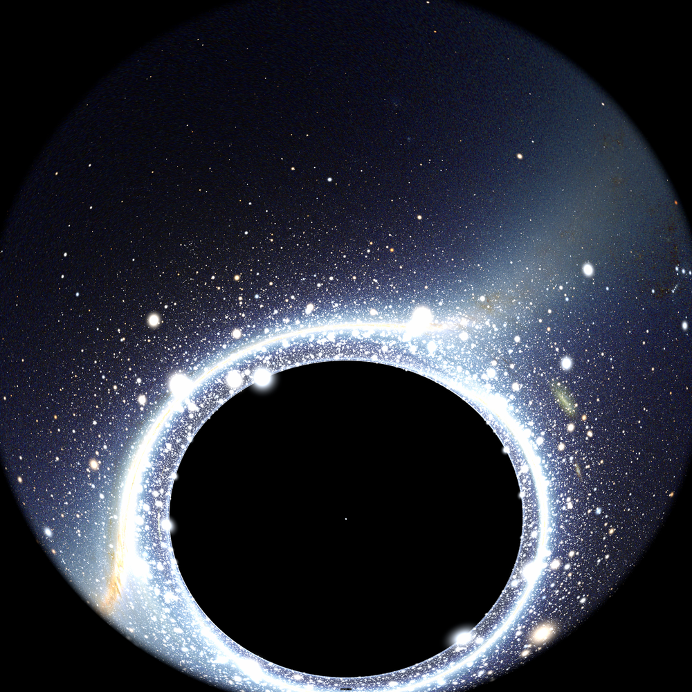
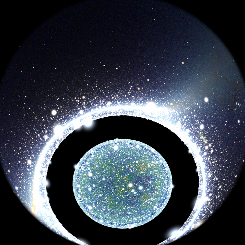
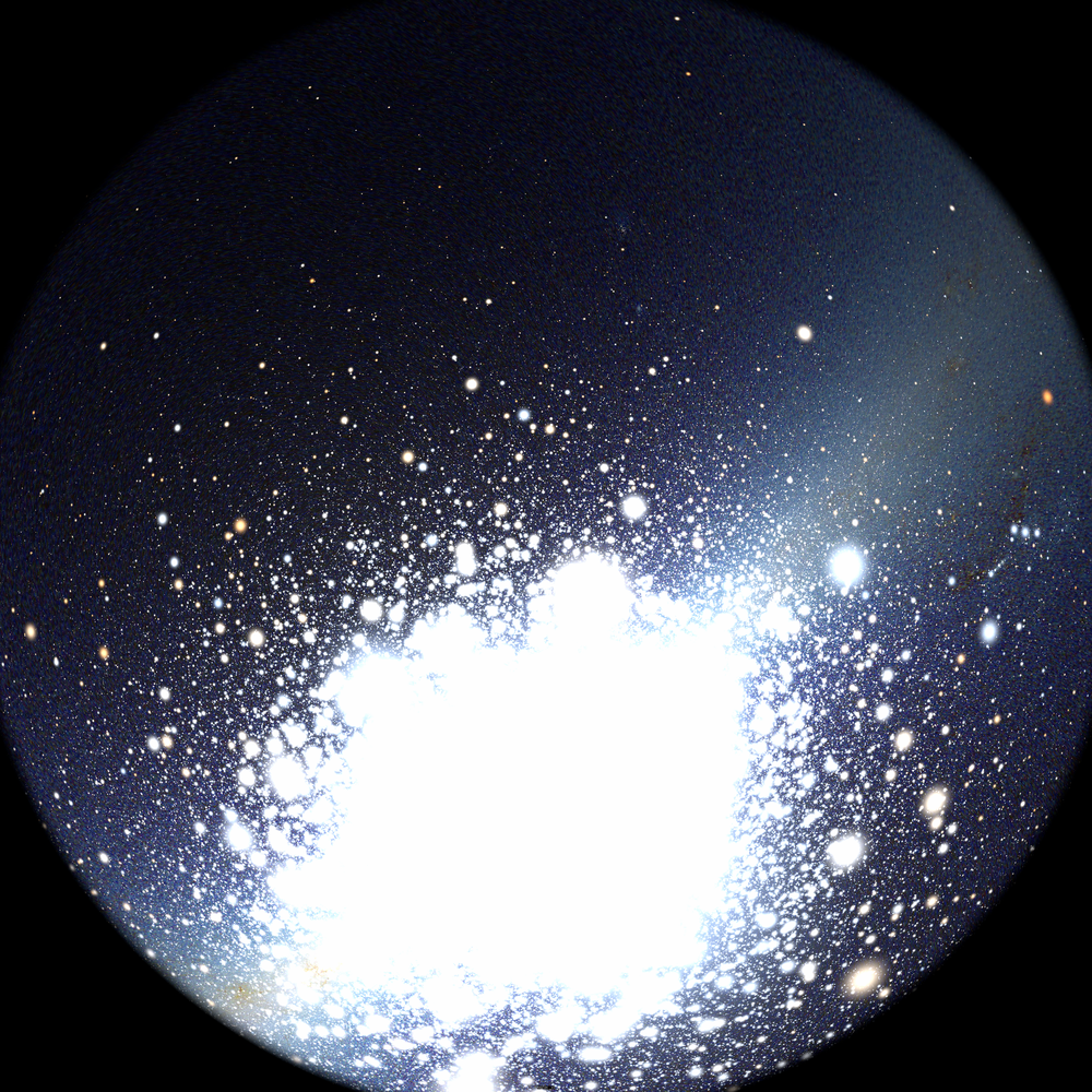
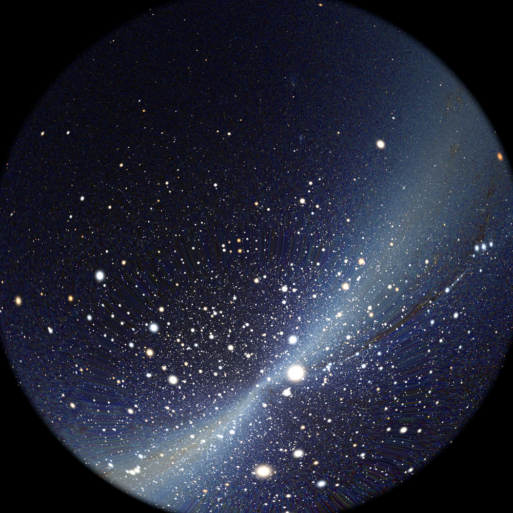
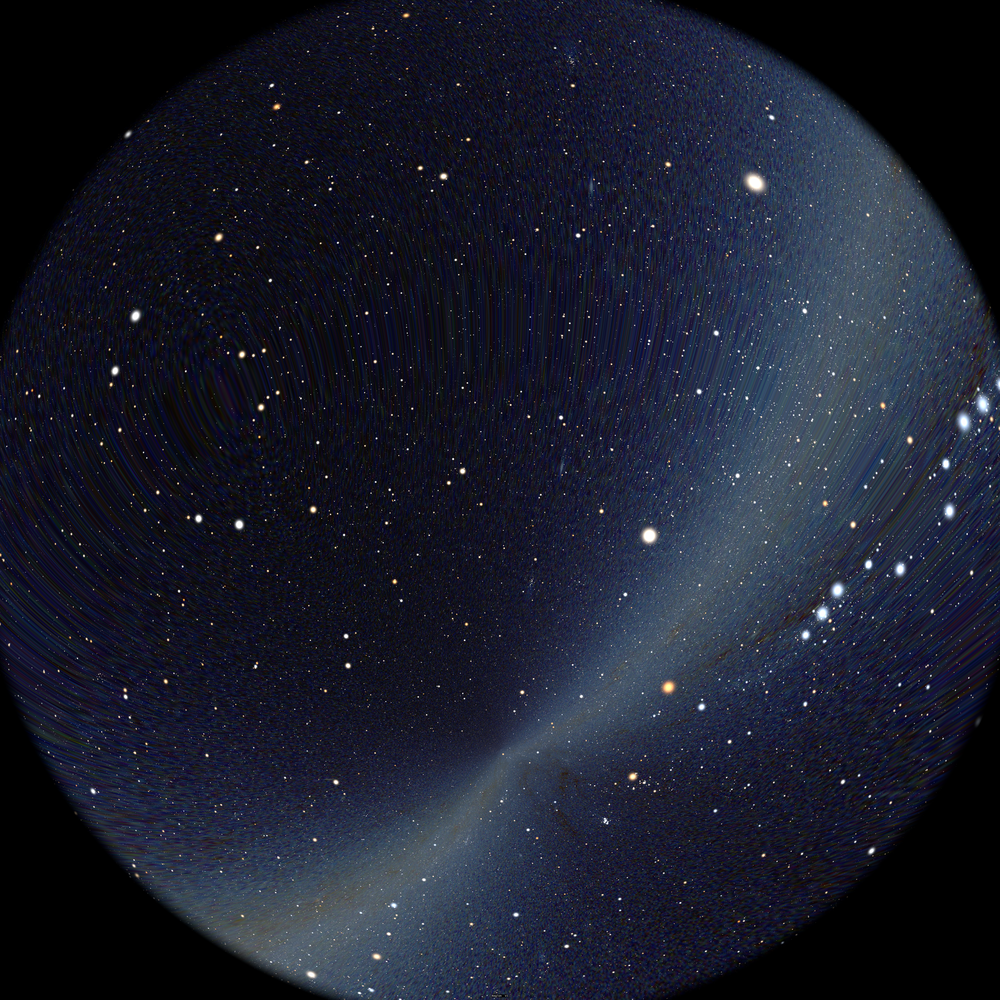
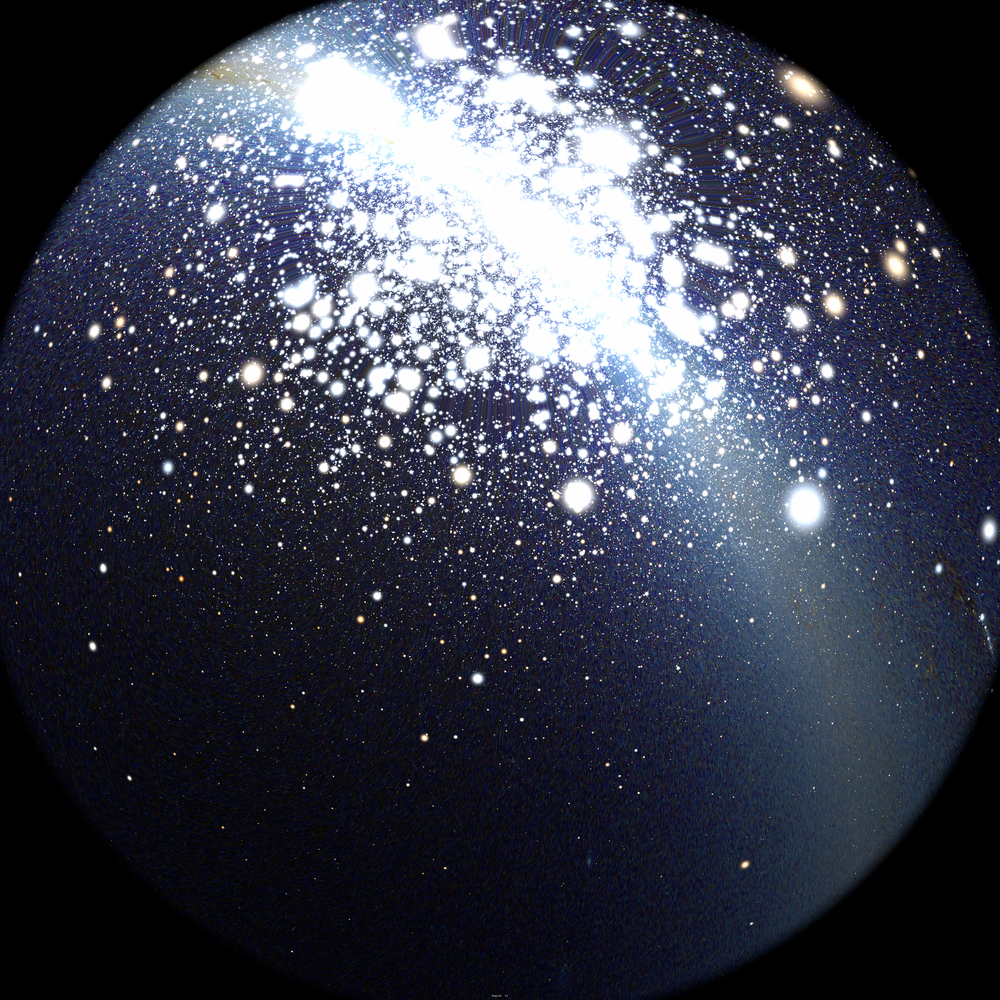
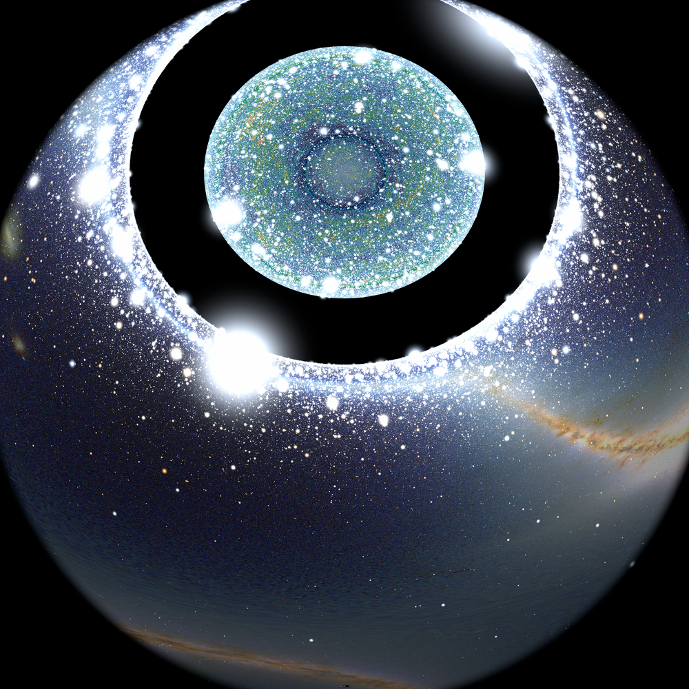
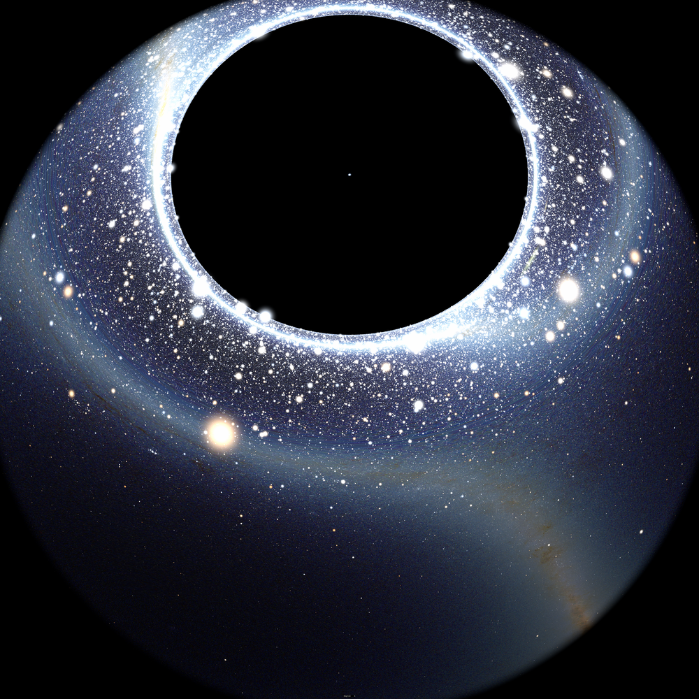
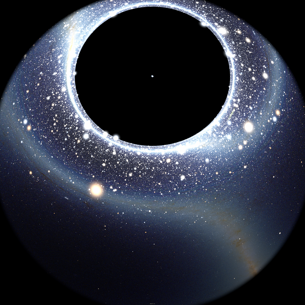
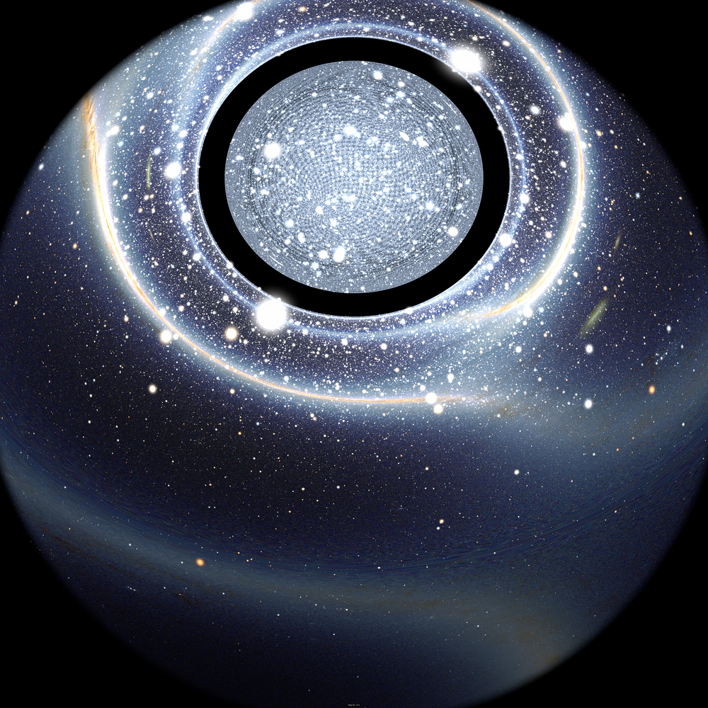
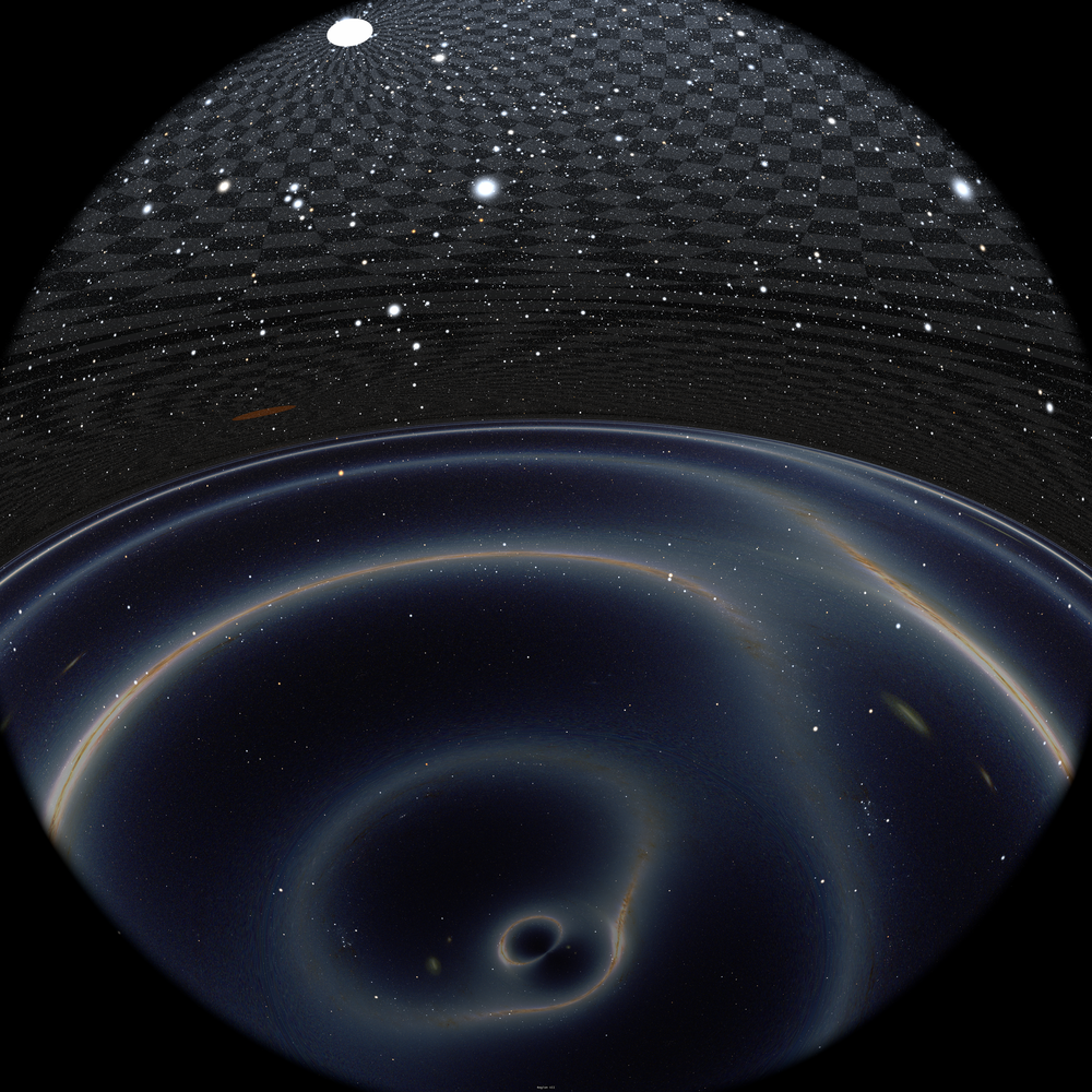
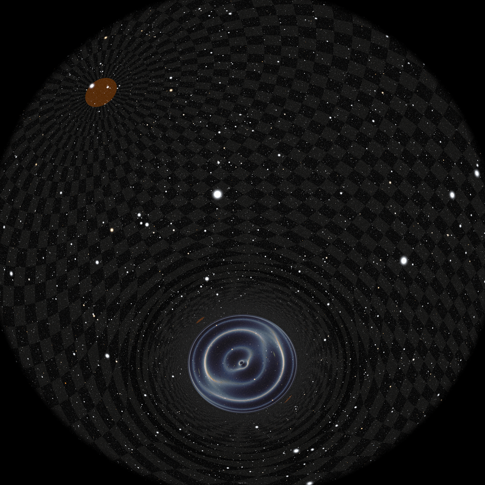
Showing all the features that arise during the crossing of a wormhole is quite demanding as many worthwhile details are seen in very different directions. We therefore chose to perform a fish-eye view of such journey, and made our computations in Domemaster format images, that is the current standard for digital planetariums. Images computed that way fill a half sphere, that is steradians, a value which is obviously barely sufficient for our purpose, since the most interesting features of the infalling part of the crossing are toward whereas the equally interesting features during the outgoing part of the journey are in the opposite direction. Therefore, we rotate the view during the journey. During all the infalling phase, the center of the coordinate system, where the wormhole lies, is shown 45 degrees above the front of the audience. When the observer bounces in region 6 the interesting part of the view corresponds to the opposite direction, and therefore would be behind the audience, 45 degrees offscreen under the edge of the screen. We therefore slowly rotate the view by 90 degrees during the outgoing phase of region 6, so that when exiting region 6, the outgoing direction is onscren, 45 degrees below the upper edge of the screen, which means behind the audience. Then, as the observer exits the wormhole and enters region 7, we rotate back the view by 90 degrees so that the center of the coordinate systems which still shows the wormhole and the region from which the observer comes from is again in front of the audience, 45 degrees above the edge of the screen. We have computed a whole movie of 2500 individual frames, some of which are shown here. In order to more easily distinguish the different regions, we used the following data for each of these:
-
•
Region 1 corresponds to the Milky Way seen from the Solar System (without the Sun nor the planets). We use 2MASS survey starless celestial sphere, to whom we add a 200k star catalog (more details are given in Ref. riazuelo15 ).
-
•
Region -5 is simulated by a random star catalog whose properties in term of number of stars vs. magnitude are similar to that of region 1. However, no pixellized celestial sphere is included, which is sufficient to distinguish between the two as region -5 is somewhat darker than region 1.
-
•
Region 3 is simulated using another mock star catalog with the same properties as above. The background pixellized celestial sphere is (rather arbitrarily) a full-sky false color Cosmic Microwave Background map which is colourful enough to be distinguished from region 1 and -5.
-
•
Region 7 is simulated with, again, a third mock star catalog, and with a coordinate grid playing the role of the celestial sphere.
Careful implementation of all the special and general relativistic effects proved to be almost impossible because of the large blueshift experienced in some parts of the trajectory. We therefore significantly attenuated the flux increase associated with frequency shift by implementing a flux increase proportional to instead of , a choice which gave a satisfying rendering, although at the cost of some qualitative differences with respect to the analytical calculations we performed earlier: (i) all the integrated fluxes are finite at horizon crossing; (ii) the flux from region 3 soon after outer horizon crossing is now smaller than that from region 3 just before inner horizon crossing. Those two differences come from the fact that the powers of in Eqns. (65, 67) are different due to our attenuation of the flux.
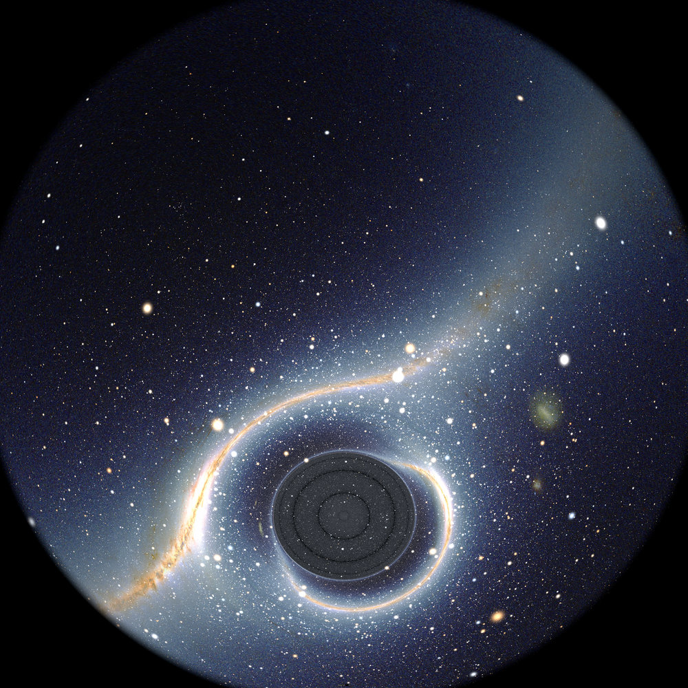
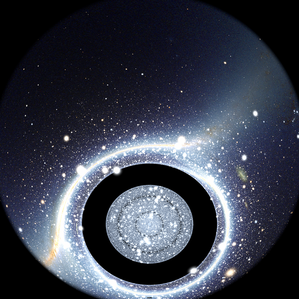
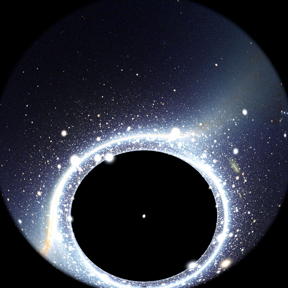
The sequence of the main features of the wormhole crossing is outlined in fifteen frames shown in Figs.18–25. For each frame, we included the corresponding deviation functions as well as frequency shift. Those are the exact values, independently of our (possibly disputable) rendering choice.















VIII Conclusion
In this paper, we have performed as thoroughly as possible a visual description of the Reissner-Nordström metric, whose richness with respect to the Schwarzschild metric induces several novel, counter-intuitive effects that could hardly be guessed from a purely formal study of the metric. In particular, we have described the observable consequences of bounded null geodesics, which led to what we called the dark shell phenomenon. We have also studied some features that arise in the case the singularity is naked. More importantly, we have made a careful, step-by-step analysis of a wormhole crossing which we simulated with very high resolution (8k8k) full dome frames.
This does not cover all the possibilities offered by the metric. For example, the wormhole study focus on a single value of and a more quantitative study of what happens for different values of this ratio was not performed. Also, we focused on an observer crossing the wormhole following a radial geodesic, but non radial and even non geodesic motion were not shown, the latter allowing for a difference sequence of region seen during and after wormhole crossing. All these aspects could possibly deserve being studied in a future work.
Appendix A Proof of Eq. (10)
Surprisingly, Eq. (10) is not given in Chandrasekhar’s book chandrasekhar83 . We therefore shall derive it here. We are interested in finding the value of such that . This amounts to find the solution of this equation :
| (97) |
Defining and , we obtain
| (98) |
We therefore need to find the root of the third order polynomial in corresponding to the right part of right hand side of above equation. However, we already know that equation admits as a double root because it is both a root of and a local extremum (so that the derivative of either or is zero there). Consequently, because we have for this extremum
| (99) |
or, conversely in term of
| (100) |
we obtain from Eq. (98)
| (101) |
We therefore are left with the resolution of a second order equation, which, going back to the variable, writes
| (102) |
Using again Eq. (100), we have
| (103) |
the solution of which is
| (104) |
Multiplying everything by then gives
| (105) |
The root we are interested in is the positive one, so that this reduces to
| (106) |
Expanding the term within the square root then leads to
| (107) |
which can further be simplified into the compact form
| (108) |
This indeed corresponds to Eq. (10). As a last note, we add that for low values of , the potential is extremely steep close to since one has , the last result coming from Eqns. (71, 72). Consequently, numerical errors sometimes give to a value that significantly differs from the correct one, i.e., for low values of (see Eq.(24)).
References
- (1) H. Reissner, Annalen der Physik, 50, 106–120 (1916).
- (2) G.Nordström, Verhandl. Koninkl. Akad. Wetenschap., Afdel. Natuurk., Amsterdam, 26, 1201–1208 (1918).
- (3) S. Chandrasekhar, The Mathematical Theory of Black Holes, Oxford University Press, England (1983).
- (4) J. Fukue & T. Yokoyama, Publ. Astr. Soc. Jap., 40, 15–24 (1988).
- (5) S. U. Viergutz, Astron. Astrophys., 272, 355 (1993).
- (6) J.-A. Marck, Class. Quant. Grav., 13, 393-402 (1996).
- (7) C. Fanton et al., Publ. Astr. Soc. Jap., 49, 159–169 (1997).
- (8) H. Falcke, F. Melia & E. Agol, Astrophysical Journal Letters, 528, L13–L16 (2000).
- (9) A. J. S. Hamilton, Bulletin of the American Astronomical Society, 36, 810 (2004); See also dedicated website http://jila.colorado.edu/{̃}ajsh/insidebh/intro.html.
- (10) K. Beckwith & C. Done, Month. Not. Roy. Astr. Soc., 359, 1217–1228 (2005).
- (11) Event Horizon Telescope website: http://www.eventhorizontelescope.org/.
- (12) R. Abuter et al. (Gravity collaboration), Astronomy & Astrophysics, 602, A94 (2017).
- (13) S.S. Doeleman et al., Science, 338, 355–358 ((2012).
- (14) R.-S. Lu et al., Astrophysical Journal, 859, 60 (2018).
- (15) R. Abuter et al. (Gravity collaboration), Astronomy & Astrophysics, 615, L15 (2018).
- (16) R. Abuter et al. (Gravity collaboration), arXiv:1810.12641.
- (17) T. Müller, General Relativity and Gravitation, 40, 2185–2199 (2008).
- (18) T. Müller & D. Weiskopf, American Journal of Physics, 78, 204–214 (2008).
- (19) T. Müller, European Journal of Physics, 36, 065019 (2015).
- (20) M. Zajacek et al., MNRAS, 480, 4408–4423 (2018).
- (21) D. Publiese, H. Quevedo & R. Ruffini, Phys. Rev. D, 83, 104052 (2011).
- (22) D. Publiese, H. Quevedo & R. Ruffini, Eur. Phys. J. C, 77, 206 (2017).
- (23) A. Riazuelo, arXiv:1511.06025v2.
- (24) W. H. Press et al., Numerical Recipes in C, edition, Cambridge University Press, Cambridge, Great Britain (1992).
- (25) R. Penrose, in Battelle Rencontres: 1967 Lectures in Mathematics and Physics, C. de Witt-Morrette & J. A. Wheeler Eds, 112–235 (1968).
- (26) É. Poisson & W. Israel, Phys. Rev., D41, 1796–1809 (1990).
- (27) M.S. Morris & K.S. Thorne, American Journal of Physics, 56, 395–412 (1988).
- (28) O. James et al., American Journal of Physics, 83, 486 (2015).