Elastohydrodynamics of swimming helices: effects of flexibility and confinement
Abstract
Motivated by bacterial transport through porous media, here we study the swimming of an actuated, flexible helical filament in both three-dimensional free space and within a cylindrical tube whose diameter is much smaller than the length of the helix. The filament, at rest, has a native helical shape modeled after the geometry of a typical bacterial flagellar bundle. The finite length filament is a free swimmer, and is driven by an applied torque as well as a counter-torque (of equal strength and opposite direction) that represents a virtual cell body. We use a regularized Stokeslet framework to examine the shape changes of the flexible filament in response to the actuation as well as the swimming performance as a function of the nondimensional Sperm number that characterizes the elastohydrodynamic system. We also show that a modified Sperm number may be defined to characterize the swimming progression within a tube. Finally, we demonstrate that a helical filament whose axis is not aligned with the tube axis can exhibit centering behavior in the narrowest tubes.
I Introduction
At the microscale, bacterial motility is achieved through the action of rotating helices lauga2016bacterial . Monotrichous cells such as Pseudomonas aeruginosa are propelled by a single helical flagellum driven by a rotary motor at its base. Peritrichous cells such as Escherichia coli are propelled by many helical flagella that, when rotating in the same direction, form a coherent helical bundle. A fascinating family of bacteria, spirochetes, have cell bodies that are themselves helical and appear to move as a corkscrew through viscous fluids charongoldstein . In addition to nature’s swimming helices, fabricated helical micromachines present intriguing possibilities in biomedical applications such as drug delivery nano2009 ; pham2015 . While varying in their material properties, these helices (individual bacterial flagella, flagellar bundles, spirochete cells, fabricated helices) are elastic structures that, when actuated in a viscous fluid, could experience shape deformation in response to the flow.
It is also of interest, both for engineered helical microswimmers and natural bacterial cells, to understand how motility is affected when moving through confined environments. Indeed, the use of bacteria in bioremediation often relies on cells moving through porous media such as soil, where the pore sizes are smaller than the flagellar length ping2015 . The effects of moving through such restrictive geometries on the swimming performance of bacterial cells has been examined both in laboratory experiments and mathematical models. Early experiments kyr1995 of E. coli swimming in glass capillary tubes of three micron diameters showed that the cells could not tumble and reorient in this confined space, and exhibited unidirectional motion. More recently, it was shown that such tumbling of E. coli was also hindered when cells were swimming close to a planar surface. Microfluidic experiments showed that E. coli cells tend to swim in helical paths in narrow capillaries ping2015 , and S. marcescens experienced a sizable boost in swimming velocity in microchannels binz2010 .
Models of microbial swimming in cylindrical capillary tubes study the performance of spherical squirmers zhu2013low and dipolar swimmers yeomans2013 . Using a boundary element method, Zhu et al. zhu2013low show that spherical squirmers with tangential deformations swim more slowly as confinement increases, but swimmers with normal deformations swim faster with confinement. The reduced model swimmers in yeomans2013 moving in the center of a rigid tube move faster with confinement. A model of a swimmer in a capillary tube that represents the detailed geometry of a rotating rigid helix was presented by Liu et al. Liu2014 . In this model, both the tube and the helix were infinitely long, but the radius of the tube was on the order of the helical radius. Except for the tightest confinements, swimming speed increased with confinement when a fixed torque was applied.
As in the model of Liu2014 , here we study the swimming of an actuated helical filament in a capillary tube whose radius is close to the helix radius. However, the helical filament in this study is flexible and of finite length. Using a regularized Stokeslet framework cortez2005method , we first examine the swimmer in free space, and show that its performance is well-characterized by the Sperm number, a non-dimensional parameter that measures the ratio of viscous fluid forces to elastic forces. We then examine the effects of confinement in a tube, and suggest a modification of the Sperm number to account for the effect of the tube surface. Finally, because the helical filament is of finite length, we can study its dynamics when it is initialized at an angle to the centerline of the tube.
II Methodology
II.1 Stokes equations
We model a flexible, helical filament that is actuated by applied torques in a viscous fluid, where the length and time scales are small enough that inertial forces are negligible. The fluid motion is therefore well-modeled by the incompressible Stokes equations:
| (1) | ||||
where is the pressure, is the fluid velocity, is the fluid viscosity, is the external force per volume and is external torque per volume exerted by the helical swimmer on the fluid.
The forces and torques in Eqn. 1 will be localized at the helical filament. These equations hold in all of three-dimensional space. To nondimensionalize the problem we assume characteristic scales for length , time , force , and torque . By choosing and , the dimensionless Stokes equations are:
Throughout this manuscript, we choose the characteristic scales to be: 4 m, 0.01 sec, to be the viscosity of water, and, hence, = N.
We use a regularized Stokeslet framework cortez2005method to model the elastohydrodynamic system, where the external force comes from a surface integral of regularized forces supported on the cylindrical surface of the helical filament, while the regularized torques are applied only at two points and . The first torque will be applied at the tip of the helix, whereas the second, of equal strength but opposite direction, will be applied slightly in front of the filament, as a proxy to a counter-rotating cell body. The expressions for force and torque are:
The regularization (or blob) function is chosen to be:
| (2) |
where . This leads to the velocities due to the regularized Stokeslets and rotlets as follows:
| (3) |
| (4) |
where is force per unit area, denotes the surface of the helical filament, is torque, , and is the regularization parameter. We note that these velocities are defined everywhere in and are everywhere incompressible.
II.2 Representation of helical filament and its actuation
The model elastic filament that we consider has a native helical equilibrium shape whose centerline is given by:
| (5) | ||||
where is the arc length of the helix, is the number of turns in the helix, and the helical radius, tapered from back to front, is given by:
| (6) |
As in Flores2005 , is chosen such that the tangent vector has unit length, so that is an arclength parameter. We do not view the helical filament as a single bacterial flagellum, but rather as a representation of a bacterial flagellar bundle. In this work, we choose a fixed equilibrium configuration of the helical filament in all simulations, whose associated geometric parameters are given in Table 1. These fall within the range of parameters for a typical, loosely packed helical bundle lauga2016bacterial ; Turner2000 ; macnab1977bacterial .
| Input Quantities | Dimensionless | Corresponding |
|---|---|---|
| value | dimensional value | |
| Helix arc length, | 5.42 | 21.7 m |
| Helix projected length, | 3.93 | 15.7 m |
| Number of pitches, | 2 | 2 |
| Helix max amplitude, | 0.5 | 2 m |
| Tapering parameter, | 6 | 6 |
| Filament radius, | 0.08 | 0.32 m |
| Rotlet strength (= 0.5 torque) | N-m | |
| Spring stiffness, | N | |
| N-m2 | ||
| Counter rotlet separation, | m | |
| Computed Quantities | ||
| Frequency, | 0.024 - 0.67 | 2.4 - 67 Hz |
| Swimming speed, | 0.0057 - 0.14 | 2.28 - 55.5 m/s |
| Distance per revolution | 0.05 - 0.34 | 0.20 - 1.4 m |
| Numerical Parameters | ||
| Cross sections along helix, | 65 | 65 |
| Points per helical cross section, | 6 | 6 |
| Cross sections along tube, | 64 | 64 |
| Points per tube cross section, | 24 - 38 | 24 - 38 |
| Spacing between helix nodes, | 0.32 m | |
| Helix blob size, | 0.025 | 0.1 m |
| Spacing between tube nodes, | 0.16 | 0.64 m |
| Tube blob size | 0.5 | 0.2 m |
| Time step, | 2.5 s - 1.0 s |
We construct the discretization of the surface of the cylindrical helical filament by placing hexagonal cross-sections of radius along the helical centerline, perpendicular to the centerline. As such, each cross-section is discretized by = 6 six points, and we take cross-sections along the helical filament so that the spacing between neighboring cross-sections is approximately equal to the spacing between adjacent points on a cross section (see Figure 1). Each of the discrete points on the surface of the filament is connected to a subset of the other surface points by a Hookean spring, giving elasticity to the structure. We define the dimensionless elastic energy in the system as
| (7) |
where is the stiffness of a spring with resting length that connects points and . The sum is over all springs. The force at is where is the area of a patch of surface centered at in the discretization. We have that
Similar constructs of semi-flexible filaments using nodes with elastic linkages have been used to model diatom chains Fauci4 and bacterial flagella peskinlim2004 ; Flores2005 . In all simulations shown here, we choose a spring topology so that each point on a given cross-section is connected to every other point on that cross-section, as well as to every other point on the two cross-sections adjacent to it. This means that each node is connected to other nodes. In addition, in all simulations shown, the stiffness constant in Eqn. 7 is taken to be the same for all springs. The resting lengths of the springs, in Eqn. 7 do vary with , and are computed during the construction of the helical surface. The initialized helical filament configuration is in its equilibrium state (the total energy in Eqn. 7 is zero).
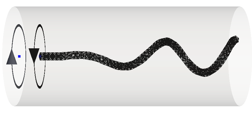
As in bacterial flagella that are driven by a rotary motor at their base, we actuate the helical filament by a regularized torque that is placed at the centroid of the first cross-section . We apply a counter-torque of the same strength and opposite direction in front of the first cross section, at a fixed distance away. In practice this is done by computing the outward normal to the first cross-section and choosing , where is a positive parameter. Due to these applied torques, the flexible filament will depart from its equilibrium shape as the network springs become stretched or compressed, causing forces at the nodes to develop. The fluid velocity due to these elastic forces and the applied torques is evaluated at each material point of the helical surface, using (Eq. (4)) and a discrete version of (Eq. (3)):
For a swimmer in free space, this velocity is used to update the positions of the nodes of the flexible filament, satisfying the no-slip boundary condition of Stokes flow. Note that since all forces arise from springs, and the torque driving the filament is balanced by a counter-torque representing the cell body, the sum of forces and torques are zero, and, hence, momentum and angular momentum are conserved. The actuated flexible helix is a free swimmer.
II.3 Coupled helix-tube system
We wish to examine the swimming of the actuated helical filament described above in a rigid, cylindrical tube whose radius is smaller than the filament length, but whose length is long enough so that no end effects on the fluid dynamics are present. The surface of the tube is discretized by circular cross-sections with points each, for a total of points. Regularized forces on these points will be computed so that the no-slip (zero velocity) condition is satisfied. These forces, plus the elastic forces supported on the helical filament, as well as the applied torques will determine the fluid velocity at any point in the tube, along with the filament’s swimming progression. Here we describe the overall algorithm for evolving this coupled helix-tube system:
Given helix surface points and forces and torques :
-
1.
Compute the velocities on the tube surface points that are induced by these forces and torques:
-
2.
Compute forces that must be exerted on the tube points so that the velocity is cancelled out there:
This is a linear system for the unknown forces . We note that the (dense) coefficient matrix depends upon the relative distances between the discrete nodes on the tube’s surface which do not change in time. This allows us to a precompute its factorization once, even though the system is solved at every time step.
-
3.
Finally, exploiting linearity of the Stokes equations, the velocities of the material points on the helical filament are:
A forward Euler method is used to evolve the positions of the helix. We note that more rigid helices require smaller time steps than flexible ones in this explicit time-stepping procedure. The positions of the two applied torques are also evolved relative to the helix. The numerical parameters used are shown in Table 1.
We remark that we also modify this algorithm to study the swimming of a rigid helix within a tube, driven by the torque/couter-torque actuation described above. In this case, given the applied torques, we need to solve for a distribution of forces at the discrete points of the tube surface and those of the helix surface so that (a) the fluid velocity is zero at the tube nodes and (b) the velocity at the helix nodes is that of a rigid translation and rotation . The six unknowns , are determined by enforcing the conditions of free-swimming (total forces and torques are zero on swimmer). We note that this entails solving a large linear system of size .
II.4 Sperm Number
As in other elastohydrodynamic systems where flexible fibers are coupled to a viscous, incompressible fluid, the relative importance of flow forces to elastic forces is an important non-dimensional parameter that governs system performance (e.g. FuPowers2007 ; ts2007 ; Wandersman1 ). Following FuPowers2007 , we define the sperm number:
| (8) |
where
| (9) |
Here, is the arc length of the helical filament, is its cross-sectional radius, is its bending rigidity, and is the rotational frequency achieved for the input torques. The perpendicular drag on the filament in free space is approximated by in Eqn. 9.
Within this set-up, the macroscopic bending rigidity of the node-spring structure depends upon the individual spring constants and the topology of the spring network. As first described in peskinlim2004 and used in Fauci4 , we can precompute the for the node-spring structure as follows: we construct a straight cylindrical fiber with the same node-spring topology and same individual spring constants, and then bend it into a circular arc with a prescribed radius of curvature . We then compute the resulting energy in the node-spring system using Eqn. 7, arriving at:
| (11) |
While the flexible helical filaments we study are motivated by bacterial flagellar bundles, we remark that the range of bending rigidities that we examine here are at the low range of bending rigidities of single bacterial flagella ( N m2) pham2015 ; darnton2007force .
III Results and Discussion
III.1 Flexible swimmer in free space
We first consider the dynamics of the actuated model helical filament in free space. In all of the simulations presented in this manuscript, the equilibrium helical shape is fixed, as is the placement of the torque/counter torque actuation (Table 1). We will, however, vary two input parameters: the stiffness of the springs comprising the filament and the strength of the rotlet that drive the rotation. We choose first to vary these separately and then analyze results in terms of the non-dimensional Sperm number.
Figure 2 shows snapshots of the emergent shapes of the same helical filament with stiffness constant actuated with increasing rotlet strengths. These snapshots are taken at times after the elastic structure has settled into a steady shape. For each rotlet strength , two projected images of the helix are shown. Note that the case of rotlet strength zero is the equilibrium configuration of the helix. Of course, if the helix were rigid () it would maintain its equilibrium shape for each rotlet strength. However, for this flexible filament (), we see that stronger actuation gives rise to smaller amplitude and larger wavenumbers (more turns in the helix). These results are reminiscent of the experiments in coq2008 where a flexible, natively straight filament was rotated in a viscous fluid. Here a shape transition to helicity was demonstrated, with smaller amplitude and larger wavenumbers emerging for larger rotation speeds.
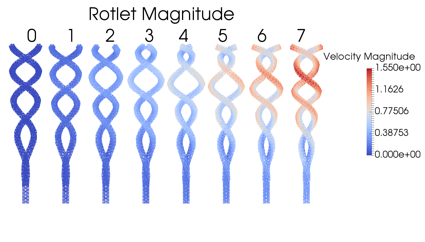
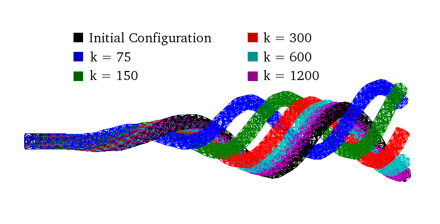
Figure 3 shows snapshots of five helical filaments with different stiffnesses actuated by the same rotlet strength 5, along with the equilibrium configuration (, in black). As in Figure 2, swimming progression is not shown because the images are repositioned so that their front sections coincide. This qualitative comparison of emerging shapes demonstrates that the more flexible filaments actuated at the same strength exhibit larger wavenumbers.
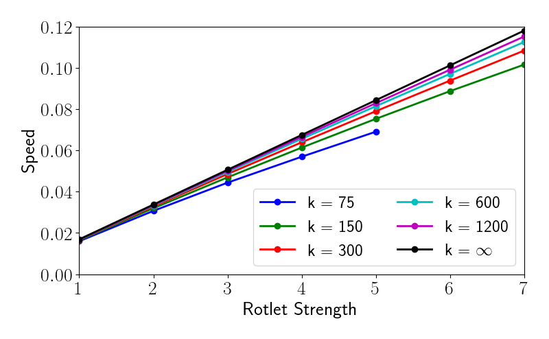
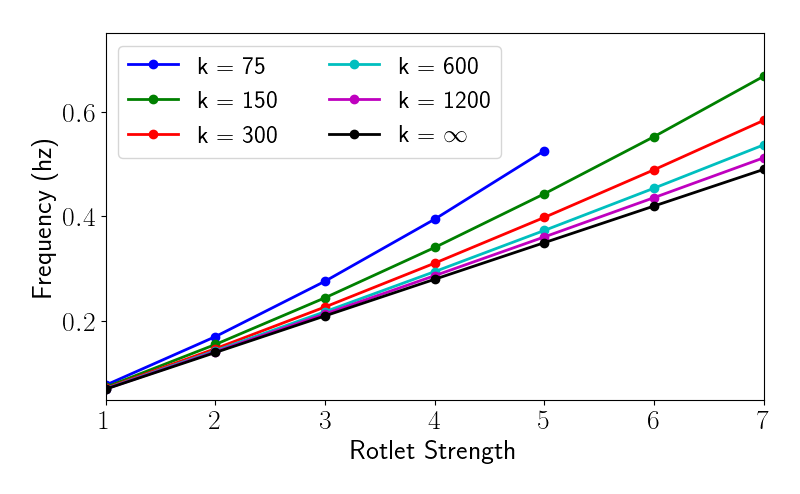
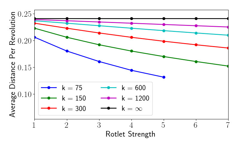
Figures 4a and 4b show the swimming speed and the rotational frequency for each helical filament as a function of rotlet strength. For the rigid filament, both speed and rotational frequency increase linearly with rotlet strength, as expected. For a fixed rotlet strength, however, we see that swimming speed decreases with flexibility while rotational frequency increases, i.e. for the same input torque, flexible helices spin faster but swim more slowly. Figure 4c shows the distance per revolution (translational distance per one spin of the helix) as a function of rotlet strength. For the rigid helical filament, this is constant. As flexibility increases, the distance per revolution decreases.
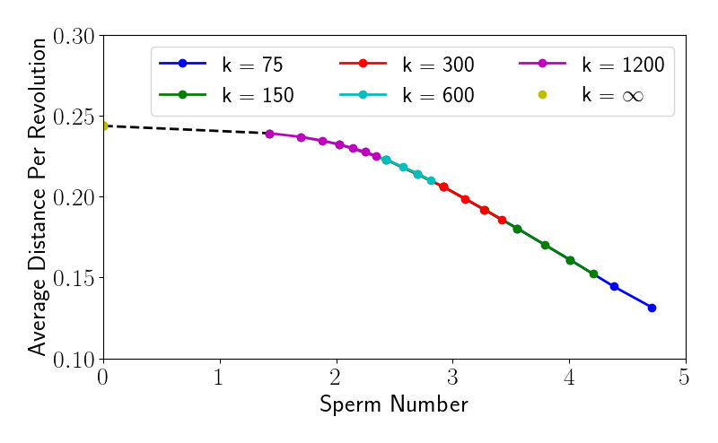
While the stiffness of the helical filament and the strength of the applied torque are two things that can be controlled separately in laboratory experiments (and in computational experiments), we see that increasing applied torque for a filament of a given stiffness is akin to decreasing filament stiffness for a given applied torque. Of course, this is evident in the definition of the Sperm number (Eqn. 8), which is a multiple of the ratio of rotational frequency to filament bending rigidity. We remark that while we do input torque, the rotational frequency is an output of the coupled fluid-filament system, so we do not know a priori. Figure 4d shows the distance per revolution measured for each of the computational simulations (six filaments of different stiffness actuated at seven rotlet strengths) plotted as a function of the non-dimensional Sperm number. The data in Figure 4c collapses nicely onto one curve. For the smallest Sperm numbers, the distance per revolution is nearly constant, but then decreases linearly for 2.5.
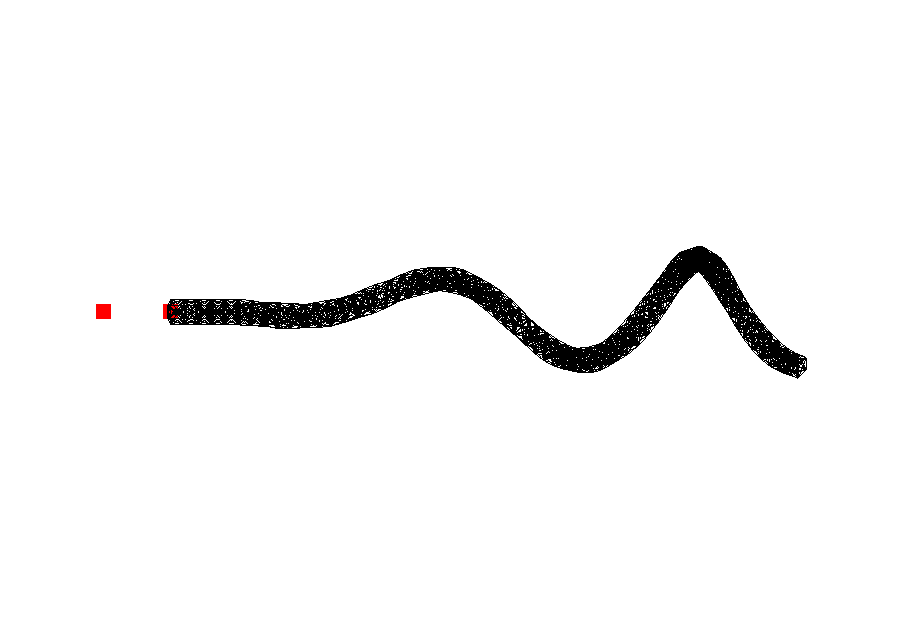
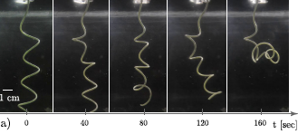
Note that in Figures 4a - 4c no swimming data is reported for the most flexible filament () actuated at the largest rotlet strengths of . While all of the filaments in the other simulations relaxed into a steady shape, resulting in periodic swimming motion, the most flexible filament that was actuated too quickly exhibited the buckling behavior shown in Figures 5a - 5d. These snapshots show the time evolution of body shape, with the last frame Figure 5d demonstrating the total loss of a straight, helical axis.
Figure 5e shows results of recent laboratory experiments of a rotating flexible helix in a viscous fluid, exhibiting this type of buckling Jawed2015 . This work quantified the dynamics of the underlying mechanical instability, and used both experiments and slender-body theory calculations to determine a critical rotational velocity for a given helix at which buckling would occur. For each applied rotation , a resulting propulsive force , nondimensionalized as was measured. Up until the critical rotational velocity , would increase as a function of , but then the propulsive force would drop dramatically as the helix buckled. While the experiments using a tethered helix measure the drop-off in propulsive force to monitor buckling, our free-swimmer calculations show the analagous drop-off in forward swimming progression when buckling occurs. Computational experiments have also demonstrated this buckling, called a “whirling instability”, in peskinlim2004 ; park2017 . We remark that buckling instabilities in the flagellar hook have been implicated as a mechanism for reorienting bacterial swimming trajectories lauga2016bacterial ; Nguyen2017 .
III.2 Flexible swimmer in tube: aligned with tube axis
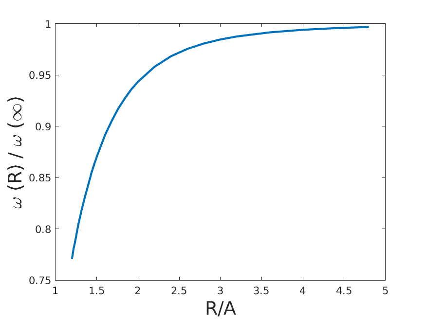
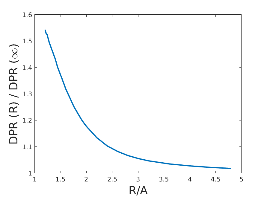
We next place our model filament inside a straight, cylindrical tube so that the straight axis of the helix coincides with the centerline of the tube (as in Figure 1). Liu et al. Liu2014 considered a related system, where a rigid, infinitely long helix was driven, either by fixed torque or fixed rotational velocity, to swim inside a capillary tube. They found that for a fixed applied torque, in all but the narrowest tubes, swimming velocity increased with confinement, until the radius of the tube was about forty percent more than that at which the helix would touch the walls of the tube. We first perform a series of simulations for a rigid, finite helical filament with the same geometric parameters as in Table 1, varying the radius of the tube . Note that the minimum value of this radius in our simulations would be . Figure 6a shows, for a fixed torque, the velocity of the helix in a tube of radius normalized by its velocity in free space as a function of the scaled tube radius . Here we see the same non-monotonic behavior in swimming speed as a function of tube radius for the finite helical swimmer as reported in Liu2014 . Figure 6b, however, shows that for a fixed applied torque, the rotational frequency of the helical filament decreases monotonically with confinement, dropping off dramatically as the helix almost touches the tube walls. Figure 6c shows that the distance per revolution increases monotonically with confinement - for a tightly-fitting helix the translational distance per turn is greatest in the tightest fits, but that turn takes a much longer time to complete.

We now examine the swimming dynamics of the flexible helical filaments in tubes of varying radii, again initialized with their axis coinciding with tube axis. Figure 7a shows the swimming speed of the flexible helical filament with as a function of rotational frequency in tubes of radii as well as in free space . Note that these simulations were performed by varying the input rotlet strength, and the rotational frequency is an output of the calculation. As expected, Figure 7a indicates that for each tube radius, the swimming speed increases with rotational frequency. We also see that the emergent rotational frequency for a fixed torque decreases as the tube diameter decreases. Finally, for all tube radii presented in Figure 7a, we see that swimming speed increases with confinement for this flexible helix. Here we have not included simulations in the narrowest tubes, as in Figure 6a which would show a drop-off in speed as radius decreases.
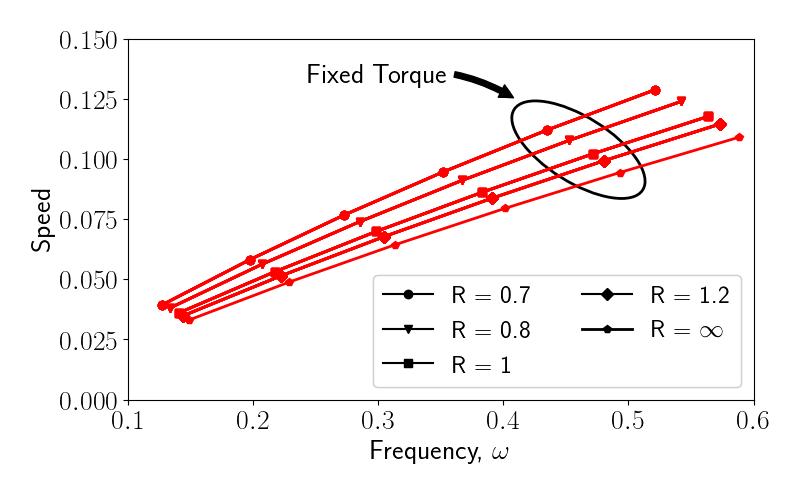
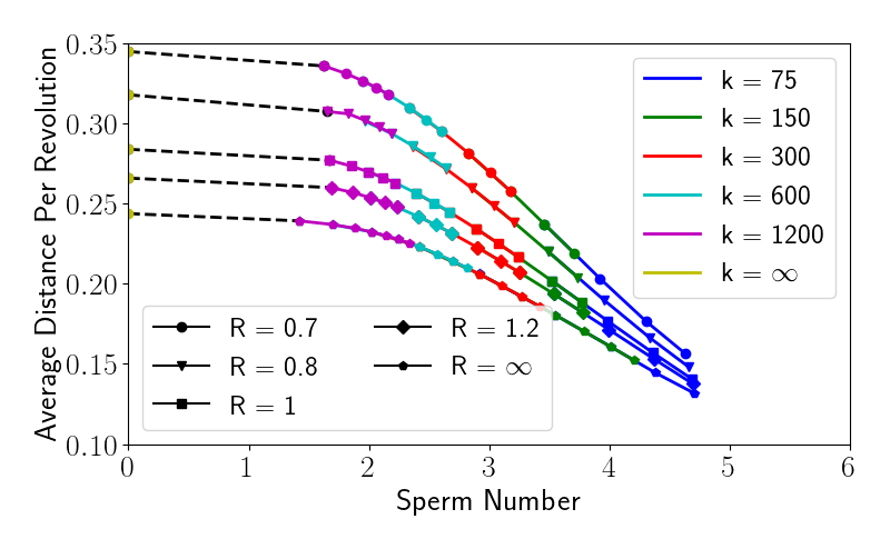
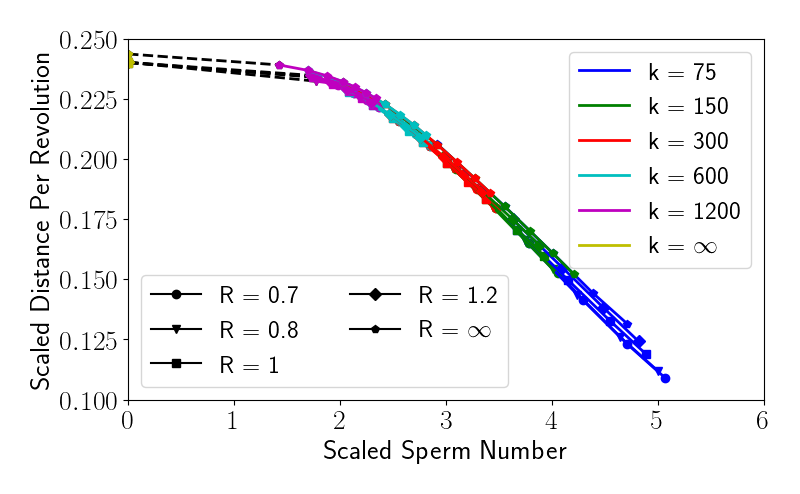
Figure 7b shows the distance per revolution achieved by actuated helical filaments in a series of simulations that varied the stiffness of the springs comprising the filament , the applied rotlet strength , and the tube radius as a function of . Note that the curve for corresponds to Figure 4d. However, we see that the data collapses to different curves, depending upon the tube radius. We have already seen that the presence of the tube affects its swimming speed and rotational velocity for an applied torque. It also affects the drag force on the helical filament. We estimate this effect by assuming that the tube-helix system is equivalent to a helix swimming in free space with an effective drag coefficient that depends upon the tube radius . Let be the swimming velocity of the helix in a tube of radius , and be the drag coefficient. The drag force on the helical filament in the presence of the tube is conceived as the same force resulting from motion in free space (at velocity ) with a modified drag coefficient:
Motivated by the work done in wham1996 for a sphere, we assume:
| (12) |
so that as , we get .
Note that the drag can also be interpreted as:
which says that the presence of the tube modifies the swimming speed by the same function .
In addition, we assume that the presence of the tube modifies the angular velocity of the helical filament through a modified rotational drag coefficient: where:
| (13) |
In order to estimate the coefficients in Eqs. 12–13, we perform a least squares fit to our velocity/angular velocity data from simulations only in the case of the rigid helical filament:
| (14) |
and
| (15) |
The distance per rotation of the helical filament is:
| (16) |
and we thus define a scaled distance per revolution by dividing by the values plotted in Figure 7b by .
Similarly, the modified sperm number is:
| (17) |
Figure 7c, shows the scaled distance per revolution as a function of the modified sperm number for all of the data points shown in Figure 7b. We see that all the data collapses onto the free space curve indicating that the two scalings we have introduced appropriately capture much of the dynamics due to the tube. We also emphasize that the evaluation of the coefficients in the expansion of the functions used only the simulation data for the rigid helical filaments in tubes of varying radii. The collapse of all data, including data from the simulations of the flexible helical filaments, is a good indication that the influence of the tube appears mostly in the form of drag–like forces and not as a consequence of deformations of the filaments. However, we see that there is greater variation in the scaled distance per revolution associated with larger , because the changes in shape as a result of the confinement are more pronounced for the more flexible swimmers.
III.3 Flexible swimmer in tube: not aligned with tube axis
In the simulations presented above, where the swimmer was initially launched so that its axis coincided with the axis of the tube, the actuated swimmer continued to remain centered. Here we examine how the swimming trajectory would change if the initial position of the helix were not aligned with the tube axis as in Figure 8. Would the swimmer eventually hit the wall? Would it straighten out its path to swim down the center of the tube? Moreover, how does this depend upon the radius of the tube? Here we present three simulations for a flexible swimmer with driven by a rotlet strength of inside of tubes of radii 0.675, 0.725, 0.775.

Figure 9 shows a sequence of snapshots in time of the swimmer in tubes of increasing radii, where the initial orientation of the helical filament formed a non-zero angle with the tube centerlines as in Figure 8. The forward progression is suppressed in these projected images. In each of the three simulations, we see that the helical shape achieved is basically the same for all three radii. However, we see that in the largest tube 0.75 (panel (c)) the angle between the horizontal tube axis and the helix axis has the greatest variation, while this angle in the smallest tube 0.675 appears to be approaching zero (panel (a)).

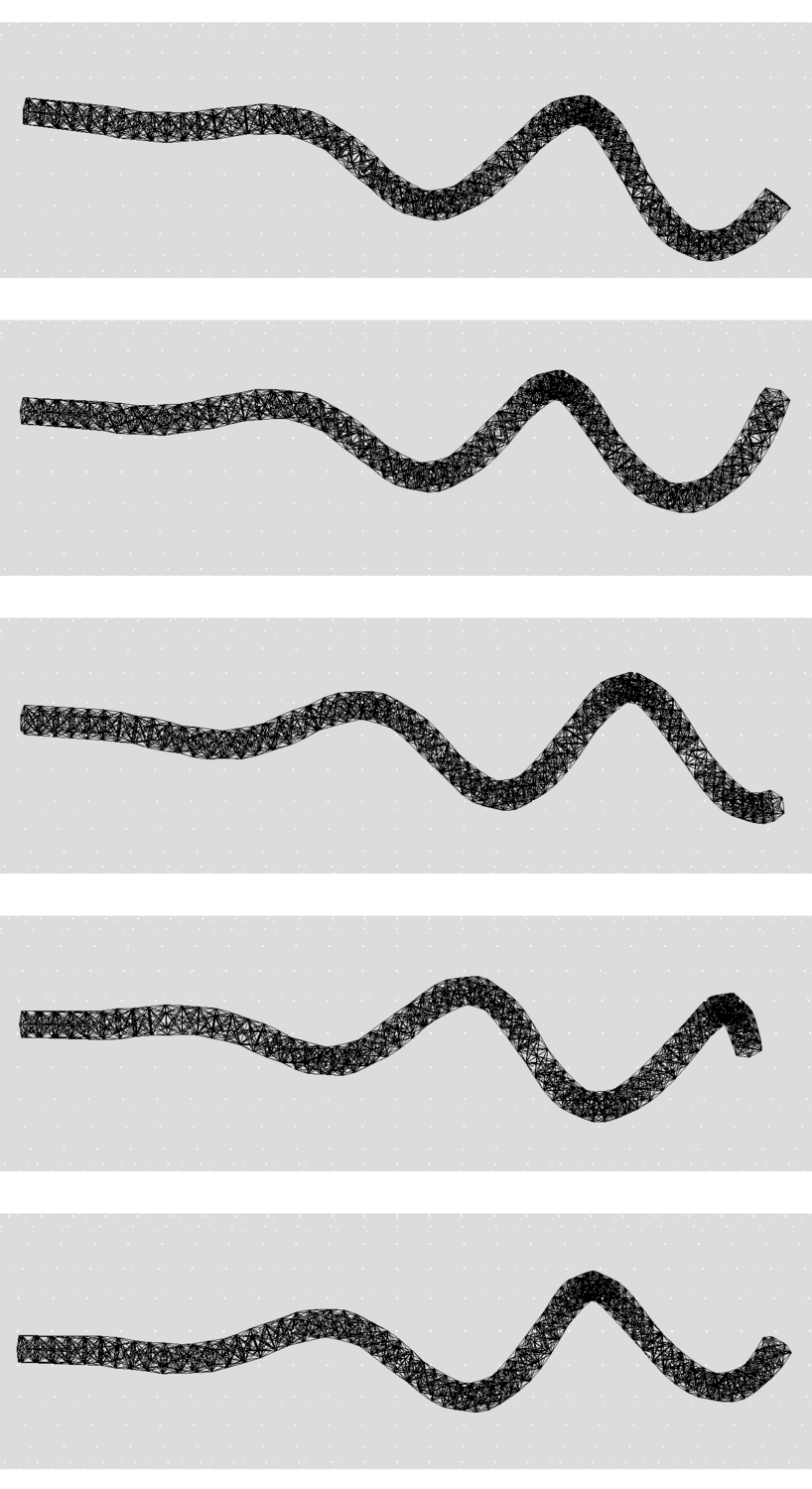
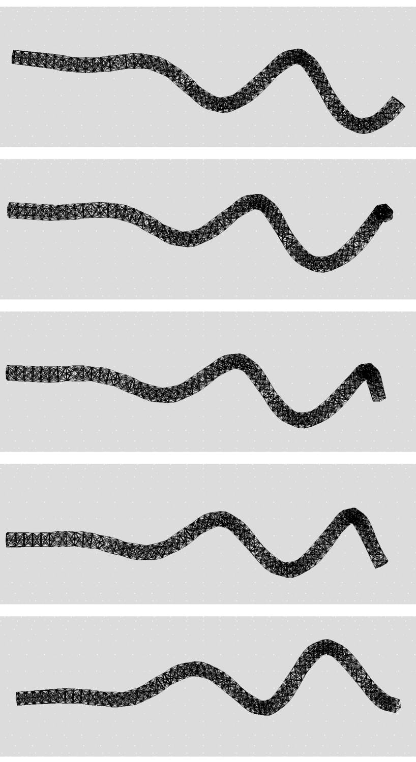
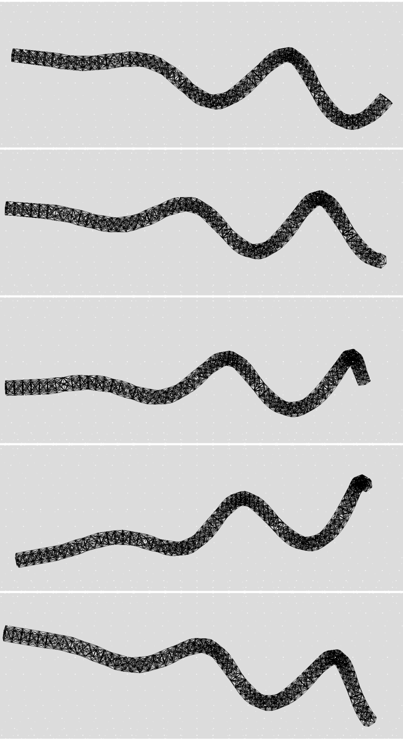
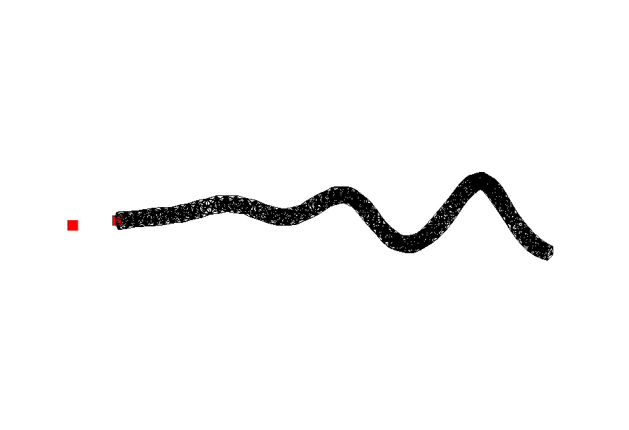
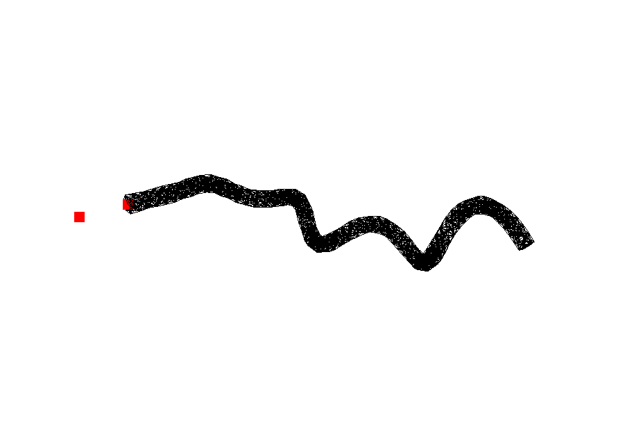
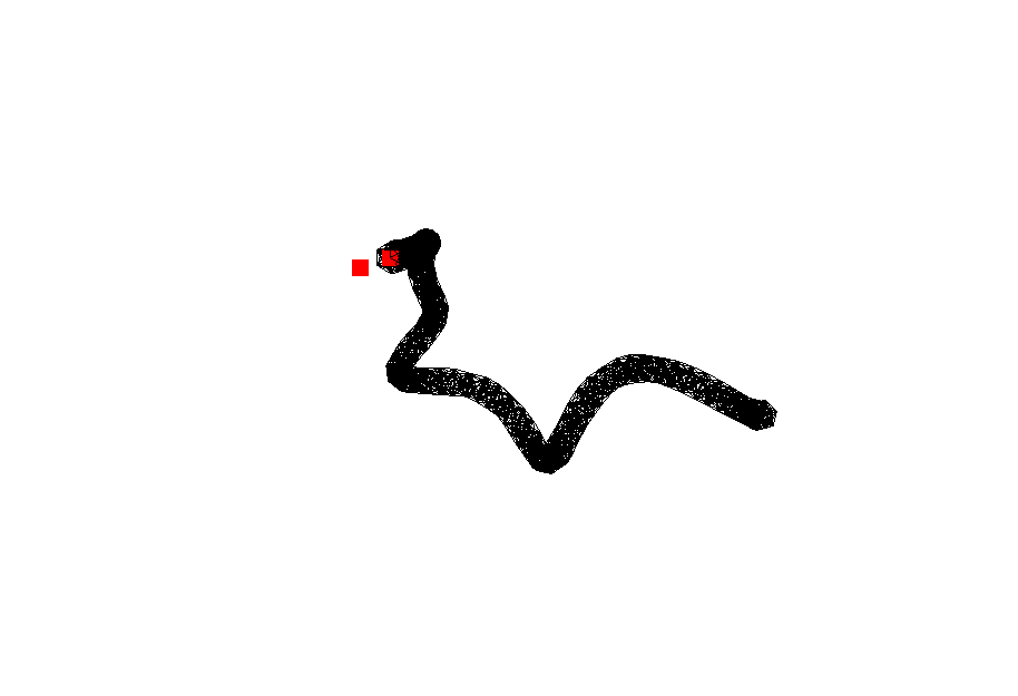
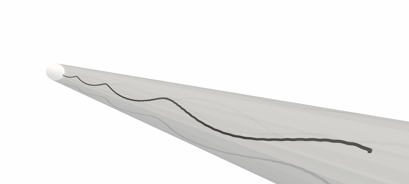
We present another view of the swimming progression in these three simulations in Figure 10. For each tube radius, there are two columns from the perspective of looking directly down the tube axis. In the right-hand-side column, we see the projection of the helical swimmer com ing toward the reader. In the left-hand-side column, we see the projected trajectory of the position of the countertorque, at time zero indicated by a star. Note that if the swimmer were aligned with the tube axis, this projected trajectory would be a single point. Figures 10(d-f) give three-dimensional views of the trajectories of the swimmers, this time looking down the tube as the swimmer moves away from the reader. We see that in the smallest tube ( 0.675), the swimmer exhibits centering behavior, with a helical trajectory whose radius is getting smaller with time. In the largest tube ( 0.775), the swimmer’s helical trajectory carries it towards the tube walls, and, in fact, because we are not including repulsion in this model, the simulation is suspended when the swimmer hits the wall. Intriguing behavior is seen in the middle sized tube ( 0.725), where the swimmer settles upon a limit cycle such that it rolls around the tube in a periodic manner, as can be seen by the projected circular trajectory of the counter-rotlet in Figure 10(b), and the three-dimensional helical trajectory in Figure 10(e).

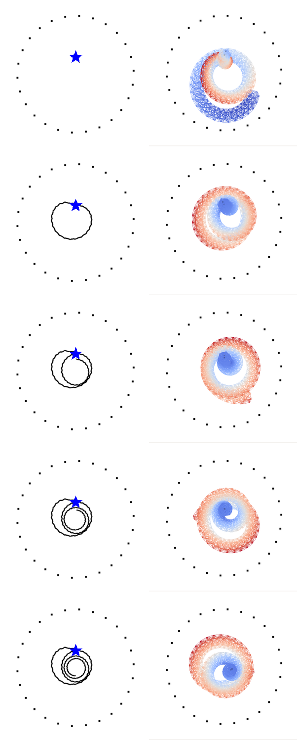
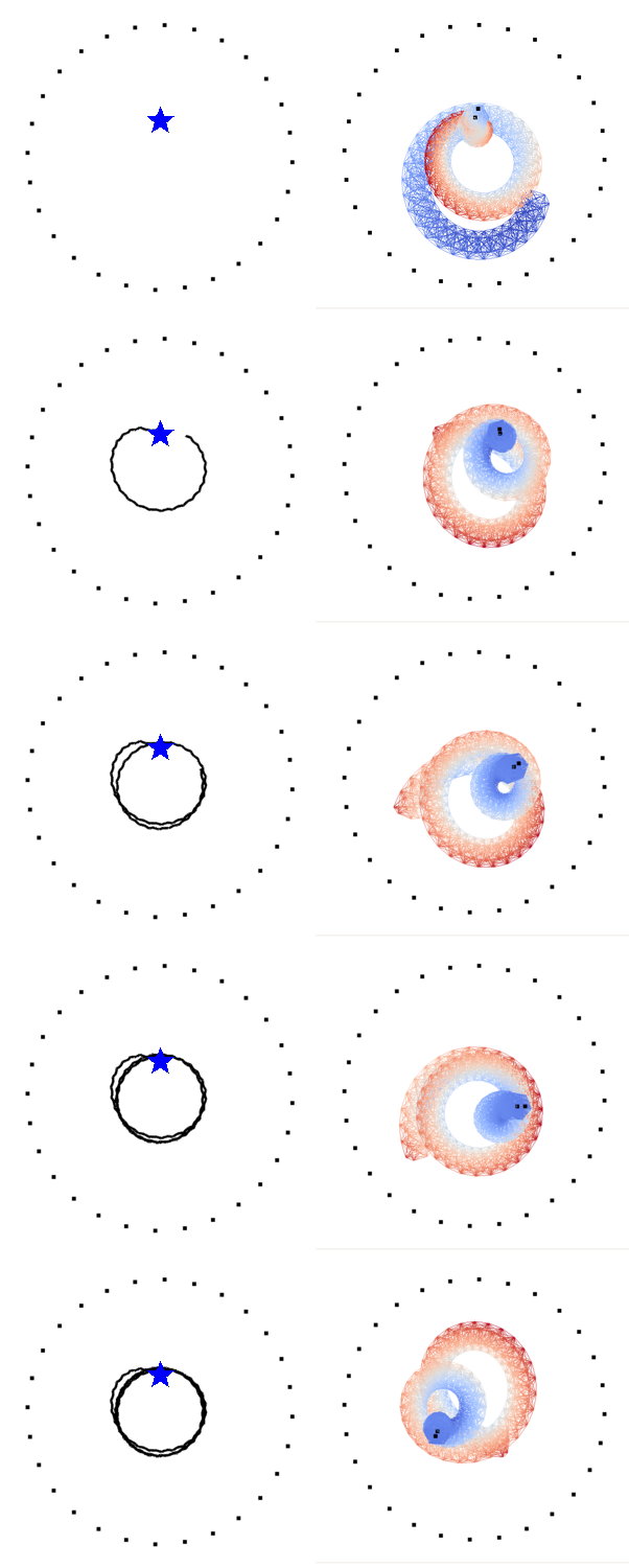
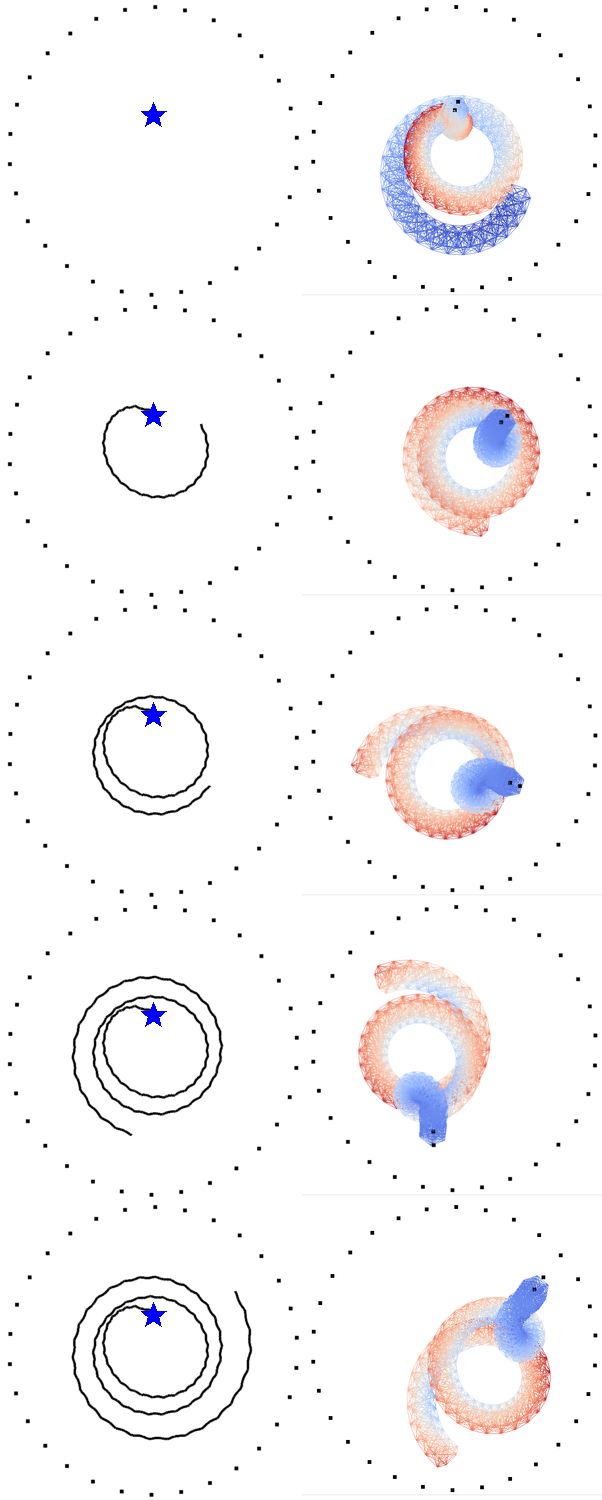
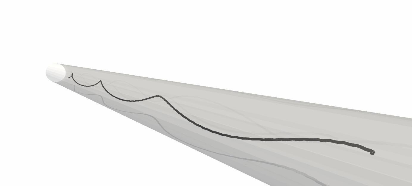
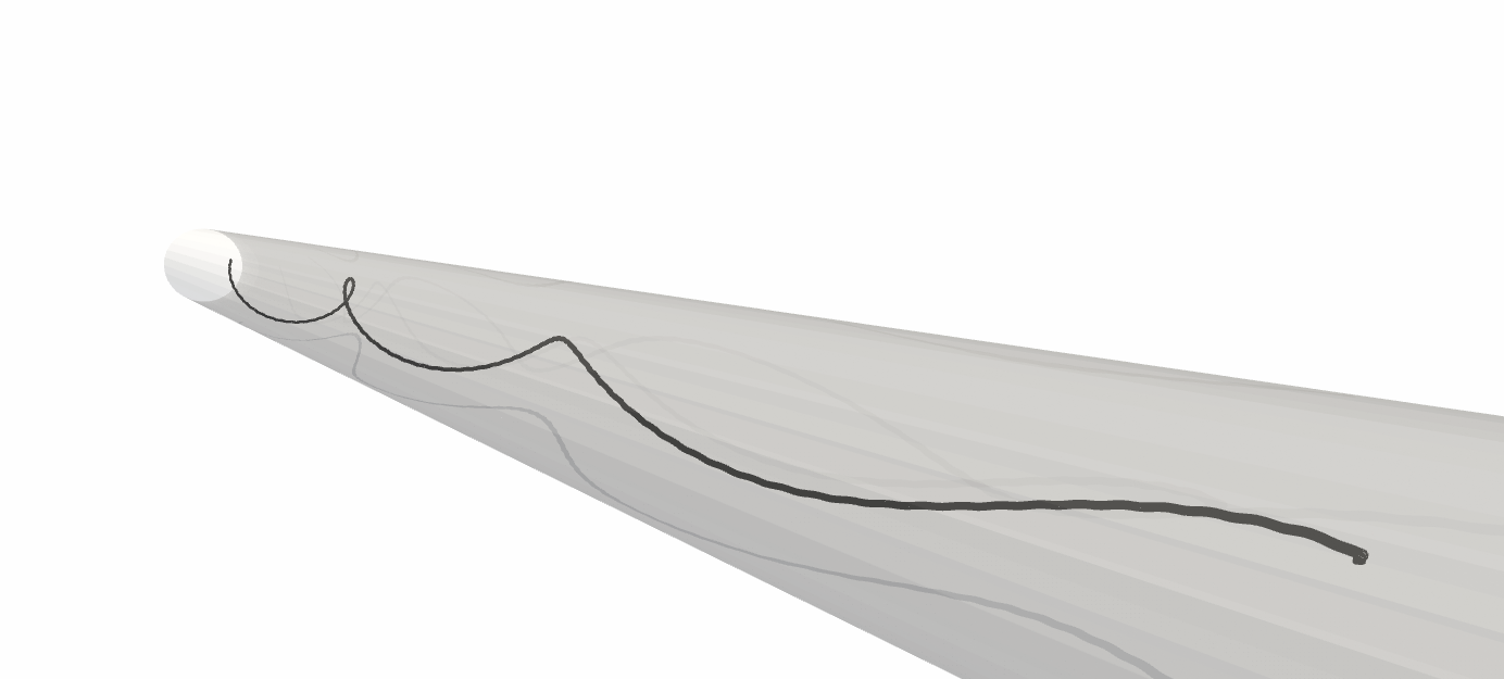
The above examples show that when the initial orientation of the swimmer is perturbed slightly from alignment with the axis of the tube, three classes of swimming trajectories emerge. These classes of swimming trajectories are consistent with the swimming trajectories computed by Shum and Gaffney ShumChannel for bacterial cells swimming between two planar boundaries. For large plate gaps, cells with long enough helical flagella were attracted to the wall, while for very narrow gaps, the swimmer relaxed to a trajectory midway between the walls. At some intermediate spacing, the swimmer “bounced” repeatedly from wall to wall.
IV Conclusions
In summary, we have considered the swimming of a flexible helix both in free space and in a capillary tube. When driven by a fixed torque/counter-torque system, the swimming velocity of the helical filament decreases with flexibility, but its rotational velocity increases. We find that the swimming performance, when measured by distance traveled per revolution, is well-described by the Sperm number. We have also demonstrated that buckling of the filament occurs for the most flexible helices actuated with large rotlet strengths ().
For the same flexible helices driven by a fixed torque/counter-torque swimming along the centerline of a tube, we find that the swimming speed increases with confinement, as does the distance traveled per revolution. This enhanced swimming performance decreases with helix flexibility. Using a modified Sperm number that accounts for the surface of the tube’s effect on drag coefficients, we again find that swimming performance in the tube can be well-described by this non-dimensional parameter.
When the alignment of the swimmer is perturbed from the tube axis, we find that for larger tubes, the swimmer will eventually hit the boundary of the tube. However, for tubes of smaller diameter, the helical swimmer actually centers itself to align with the tube axis. This finding, along with similar results for swimmers between planar boundaries ShumChannel suggest the provocative idea that bacterial cells may have an easier time breaking through a tightly-packed porous medium with small pores. Bacteria moving through large pores are likely to adhere to the matrix.
V Acknowledgements
This research was supported by the National Science Foundation grant DMS-1043626 and the Gulf of Mexico Research Initiative. The authors would like to thank Kyriakos Papadopoulos and Mengyuan Zheng for helpful discussions.
References
- [1] M. Binz, A. Lee, C. Edwards, and D. Nicolau. Motility of bacteria in microfluidic structures. Microelec. Engr., 87:810, 2010.
- [2] N.W. Charon and S.F. Goldstein. Genetics of motility and chemotaxis of a fascinating group of bacteria: The spirochetes. Annual Review of Genetics, 36(1):47–73, 2002.
- [3] N. Coq, O. du Roure, J. Marthelot, D. Bartolo, and M. Fermigier. Rotational dynamics of a soft filament: Wrapping transition and propulsive forces. Phys. Fluids, 20:051703, 2008.
- [4] R. Cortez, L. Fauci, and A. Medovikov. The method of regularized stokeslets in three dimensions: analysis, validation, and application to helical swimming. Physics of Fluids, 17(3):031504, 2005.
- [5] N.C. Darnton and H.C. Berg. Force-extension measurements on bacterial flagella: triggering polymorphic transformations. Biophysical journal, 92(6):2230–2236, 2007.
- [6] H. Flores, E. Lobaton, S. Méndez-Diez, S. Tlupova, and R. Cortez. A study of bacterial flagellar bundling. Bulletin of Mathematical Biology, 67(1):137–168, 2005.
- [7] Henry C. Fu, Thomas R. Powers, and Charles W. Wolgemuth. Theory of swimming filaments in viscoelastic media. Phys. Rev. Lett., 99:258101, Dec 2007.
- [8] M. K. Jawed, N. K. Khouri, F. Da, E. Grinspun, and P. M. Reis. Propulsion and instability of a flexible helical rod rotating in a viscous fluid. Phys. Rev. Lett., 115:168101, October 2015.
- [9] E. Lauga. Bacterial hydrodynamics. Annual Review of Fluid Mechanics, 48:105–130, 2016.
- [10] R. Ledesma-Aguilar and J. Yeomans. Enhanced motility of a microswimmer in rigid and elastic confinement. Phys. Rev. Letters, 111:138101, 2013.
- [11] S. Lim and C.S. Peskin. Simulations of the whirling instability by the immersed boundary method. SIAM J. Sci. Comp., 25(6):2066–2083, 2004.
- [12] B. Liu, K. Breuer, and T. Powers. Propulsion by a helical flagellum in a capillary tube. Physics of Fluids, 26(1):011701, 2014.
- [13] Z. Liu and K. Papadopoulos. Unidirectional motility of escherichia coli in restrictive capillaries. Appl. Environ. Mocrob., 61:3567, 1995.
- [14] R.M. Macnab. Bacterial flagella rotating in bundles: a study in helical geometry. Proceedings of the National Academy of Sciences, 74(1):221–225, 1977.
- [15] F. Nguyen and M. Graham. Buckling instabilities and complex trajectories in a simple model of uniflagellar bacteria. Biophysical Journal, 112(5):1010–1022, 2017.
- [16] H. Nguyen and L. Fauci. Hydrodynamics of diatom chains and semiflexible fibres. J. Royal Soc. Interface, 11:20140314, 2014.
- [17] Y. Park, Y. Kim, W. Ko, and S. Lim. Instabilities of a rotating helical rod in a viscous fluid. Phys. Rev. E, 95:022410, 2017.
- [18] J. Pham, A. Morozov, A. Crosby, A. Lindner, and O. du Roure. Deformation and shape of flexible, microscale helices in viscous flow. Phys. Rev. E, 92:0110004, 2015.
- [19] L. Ping, V. Wasnik, and E. Emberly. Bacterial motion in narrow capillaries. FEMS Micro. Ecol., 91:1, 2015.
- [20] H. Shum and E. Gaffney. Hydrodynamic analysis of flagellated bacteria swimming near one and between two no-slip plane boundaries. Phys. Rev. E, 91:033012, Mar 2015.
- [21] A.K. Tornberg and M Shelley. Simulating the dynamics and interactions of elastic filaments in Stokes flow. J. Comp. Phys., 196:8–40, 2007.
- [22] L. Turner, W.S. Ryu, and H.C. Berg. Real-time imaging of fluorescent flagellar filaments. Journal of Bacteriology, 182(10):2793–2801, 2000.
- [23] E. Wandersman, N. Quennouz, M. Fermigier, A. Lindner, and O. du Roure. Buckled in translation. Soft Matter, 6:5715–5719, 2010.
- [24] R. M. Wham, O. A. Basaran, and C. H. Byers. Wall effects on flow past solid spheres at finite reynolds number. Industrial & Engineering Chemistry Research, 35(3):864–874, 1996.
- [25] L. Zhang, J. Abbott, L. Dong, K.E. Peyer, B.J. Kratochvil, H. Zhang, C. Bergeles, and B.J. Nelson. Characterizing the swimming properties of artificial bacterial flagella. Nano Letters, 9(10):3663–3667, 2009.
- [26] L. Zhu, E. Lauga, and L. Brandt. Low-reynolds-number swimming in a capillary tube. Journal of Fluid Mechanics, 726:285–311, 2013.