Deep Learning from Shallow Dives:
Sonar Image Generation and Training for Underwater Object Detection
Abstract
Among underwater perceptual sensors, imaging sonar has been highlighted for its perceptual robustness underwater. The major challenge of imaging sonar, however, arises from the difficulty in defining visual features despite limited resolution and high noise levels. Recent developments in deep learning provide a powerful solution for computer-vision researches using optical images. Unfortunately, deep learning-based approaches are not well established for imaging sonars, mainly due to the scant data in the training phase. Unlike the abundant publically available terrestrial images, obtaining underwater images is often costly, and securing enough underwater images for training is not straightforward. To tackle this issue, this paper presents a solution to this field’s lack of data by introducing a novel end-to-end image-synthesizing method in the training image preparation phase. The proposed method present image synthesizing scheme to the images captured by an underwater simulator. Our synthetic images are based on the sonar imaging models and noisy characteristics to represent the real data obtained from the sea. We validate the proposed scheme by training using a simulator and by testing the simulated images with real underwater sonar images obtained from a water tank and the sea.
I Introduction
In many underwater operations [1, 2, 3, 4, 5, 6, 7], perceptual object detection and classification are required, such as search and rescue, evidence search, and defense missions for military purposes. Bodies of water often present a critical decrease in visibility due to the high density of fine floats or aquatic microorganisms [8]. Due to this limitation of using optical images, imaging sonar has been a widely accepted solution providing reliable measurements regardless of the water’s turbidity [9, 10]. Although sonars extend the perceptual range, the resulting images follow a different projection model, resulting in less intuitive and low-resolution images and cannot be easily understood by human operators. In addition, due to the sensor’s physical characteristics, a considerable level of noise is generated in the water image, so it is difficult to ensure the reliability of sonar image analysis and identification [11].

Early work on sonar image-based classification was aimed at ATR (ATR) or sediment classification. Low resolution and image ambiguity due to the shadowing effect has always been an issue in defining handcrafted features for sonar images. Galceran et al. used multibeam, forward-looking sonar to detect man-made objects [12]. In their work, they applied a series of estimation modules to detect objects. In [13], the authors employed power spectral analysis methods for seafloor sediment classification. In [14], the author reported a useful measure for sonar imaging called lacunarity to classify seafloor characteristics.
Recently, to overcome these challenges, deep-learning-based approaches have been introduced. Researchers focused on a partial application. They exploited feature learning by learning features from the CNN (CNN) and then piped the learned feature into another machine learning algorithm like a SVM (SVM) [15]. Other researchers used deep learning in a more end-to-end fashion. In [16], target classification using SAS (SAS) images was introduced. Two target objects were considered in the study, and the performance of the CNN-based approach was compared to that of the typical feature-based classifier. Kim et al. also focused on applying deep learning for vehicle detection using forward-looking sonar [17]. In the aforementioned approaches, however, the authors collected real sonar images and divided them into training and test image sets.
When applying deep learning based approaches in underwater environment, training with real sonar images from the target environment would be optimal but is highly challenging in several aspects. First, the underwater imaging specifically for classification results in a biased dataset. Second, obtaining underwater images demands time and effort. Applying deep learning underwater addresses the major challenge of scanty data. Many efforts have been made to alleviate the training data shortage. For example, [18] exploited existing pre-trained weights from in-air images. They applied fine tuning using sonar images.
A similar strategy to ours recently found in the literature synthetically generates photo-realistic images. Authors in [19] examined the synthetic training set generation by applying a proper background of white noise to the simulated images. This synthetic training image generation was also thoroughly handled in [20]. The authors evaluated the GAN (GAN) to learn underlying features in an unsupervised manner. They also examined the effect of style transfer on background and shadow generation ability.
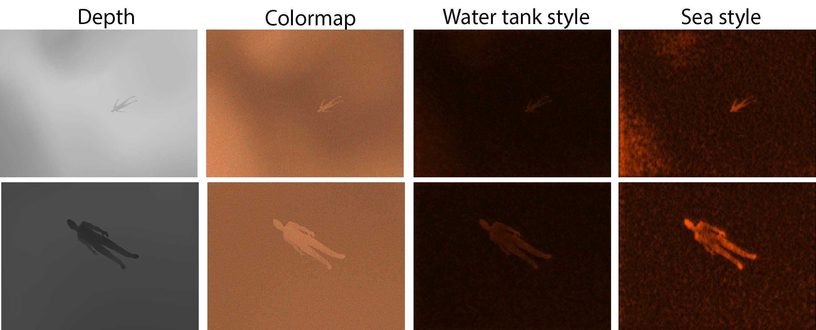
Differing from those early studies who focused on generation of images, this paper proposes an end-to-end solution to prepare a training dataset for underwater object detection and validating with real underwater sonar images. In Fig. 1, we present a simulator-based training data generation tool specifically for underwater sonar images. Our contributions are as follows:
-
•
We propose a solution to the problem of scanty data in underwater sonar applications by proposing synthetic training image generation via style transfer. The proposed method takes one channel depth image from a simulator to provide various aspects (e.g., scale, orientation and translation) of the captured data.
-
•
We performed a thorough evaluation using real sonar data from pool and sea trial experiments to validate the proposed method. Specifically, we present that the proposed simulation trained network performs equally well as the real sea data trained network. By doing so, the proposed training scheme alleviates the training data issue in underwater sonar imaging studies.
-
•
We also verified the trained network with sample images from various sonar sensors. The test sonar images are sampled from video provided by sonar companies. This validation proves the proposed scheme could be widely applicable for sonar images captured from various underwater environment. Note that the sonar data used in testing was never been used in training phase. Therefore, we suggest elimination of the real-data acquisition phase in deep learning for underwater application.
II Training Set Generation
In this section, we introduce simulation-created training data generation for underwater object detection.
II-A Base Images Preparation from Simulator
Obtaining real images from the ocean would be ideal, as reported in [16], where the author collected eight years of data from marine missions to prepare and test classifications. However, as reported, data collection in underwater missions is demanding. To overcome this limitation, we captured a base image for the synthetic training dataset from a simulated depth camera in the UWSim [21]. Using a simulator allowed us to train with various objects by loading a 3D CAD model of the target objects. By diversifying pose and capturing altitude, multiple scenes of objects were collected, as shown in the sample scene in Fig. 1.
The UWSim provides a diverse choice of underwater sensor modalities, and users may be able to implement their own sensor module within the simulator [22]. Developing a detailed sensor module for a specific perceptual sensor would require careful design of the modules in the simulator based on the detailed understanding of the sensor and the environment. However, we found that generating a photo-realistic image from a rather simple depth image may provide a feasible solution. Specifically, we proposed using the style transfer to generate realistic-enough synthetic sonar images for training, and the simulator only needed to provide a basic representation of the scene for style transfer to be applied.
II-B Image Synthesizing
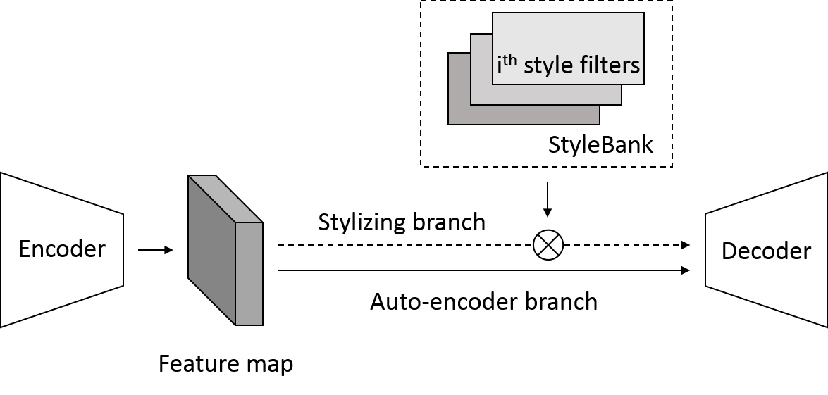
Given this base image, we adopted the StyleBankNet [23] to synthesize the noise characteristics of sonar images acquired in various underwater environments, such as water tank and sea. This network simultaneously learns multiple target styles using an encoder (), decoder (), and StyleBank (), which consists of multiple sets of style filters (Fig. 2). Each set of style filters represents the style of one underwater environment.
| Name | Architecture |
|---|---|
| Encoder | |
| Decoder | |
| style filters in SB |
II-B1 Losses
There are two different branches in the StyleBankNet: auto-encoder branch () and stylizing branch (). The StyleBankNet uses these branches to decouple styles and contents of sonar images. The auto-encoder branch uses a reconstruction loss to train the encoder and decoder for generating an output image that is as close as possible to an input image.
| (1) |
where and is input and output images, respectively. The stylizing branch uses a perceptual loss to jointly train the the encoder, decoder, and StyleBank [24]:
| (2) |
where is one of images with style. , , and are feature reconstruction loss, style reconstruction loss, regularization loss, and ATKI (ATKI) loss, respectively [24]. In this equation, the style reconstruction loss measures the difference between output and style images in style such as colors, textures, patterns, etc:
| (3) |
where and G are feature map and Gram matrix computed from layer of VGG-16 layers , respectively.
The last term is a ATKI loss. We added it to the original perceptual loss [24], as the StyleBankNet is able to learn the unique intensity distribution characteristics of sonar images. In a sonar image, some parts appear much brighter than other parts. These brighter parts may contain objects of interest because sonar signals are reflected by objects and floors. Although the intensity distribution of the brighter parts is much different from the global intensity distribution, it is likely to be overlooked when computing the style reconstruction loss to train the StyleBankNet because the brighter parts are usually much smaller than other parts. As a result, the characteristics of the brighter parts are not learned appropriately. Motivated by the ATKI [25], the ATKI loss is used to measure the intensity distributions of brighter parts in output and style images.
| (4) |
where and are the largest intensity values in grayscale output and style images, respectively. By applying the ATKI loss, the unique intensity distributions can be synthesized by the StyleBankNet.

The effect of ATKI loss is depicted in Fig. 3. When additionally using the ATKI loss, the target object appears more clearly and brightly than when not using the loss.
II-B2 Training
The dataset for training the StyleBankNet consists of a content set, which is composed of base images and multiple style sets (e.g., pool and sea). Each set contains object-centered 300 images. A single mini-batch consists of randomly sampled content images and style images with style indices. To better examine generalized characteristics of sonar images, a pair between base and style images is not fixed in each iteration. A ()-step alternative training strategy is employed to ensure a balanced learning of the encoder, decoder, and StyleBank using two branches [26]. Parameters of the StyleBankNet is updated in every iteration using the auto-encoder branch; otherwise, the styling branch is used.
III Application to Object Detection
III-A CNN Architecture
We used the deep learning toolbox including the Faster R-CNN (R-CNN) [27] model released in Matlab for underwater object detection. Although the region proposal algorithms such as EdgeBoxes [28] or Selective Search [29] are typically applied, the use of these techniques becomes the processing bottleneck in the older model [30]. Faster R-CNN addresses this issue by implementing the region proposal mechanism using the CNN and thereby making region proposal in the CNN training and prediction steps. For this RPN (RPN) training, the layers were basically set up as follows; Input layer (), 1st Convolution layer (), Relu, MaxPooling (), 2nd Convolution layer (), Relu, MaxPooling(), 3rd Convolution layer(), Relu, MaxPooling(), Fully-connected Layer(200), Relu, Fully-connected Layer(2), Softmax Layer, Classification layer. In some training cases, the hyper-parameters were slightly reduced compared to this base model.
III-B Training Image Augmentation
The style transferred image can be directly used for training, and the synthesized images themselves could be sourced for many sonar imaging applications. In this application, we propose a synthesizing scheme generally applicable to various sonar images. Thus, in this augmentation phase, we converted the images to grayscale and their inverted image in the form of general one-channel sonar images. Including inverted images is critical for sonar images because when an object is imaged by sonar, the intensity of the object may be brighter or darker than the background depending on the relative material property of the object and environment. To remedy this situation, we generated two types of images from a single channel synthesized image, as shown in Fig. 1.
For deep learning application, ensuring sufficient diversity in training datasets is meaningful. When capturing data from the simulator, physical diversity was considered to include various rotation, translation, and scaling. Additionally, we randomly flipped the captured base images. We applied variations in scale, rotation, and translation for the training dataset.
IV Experimental Results
In this section, we provides a series of experiments to evaluate style transfer performance and its application to object detection.
| Name | Environment | Description | # of Images |
|---|---|---|---|
| SIM | UWSim | Simulated depth camera | 370 |
| SIM-POOL | UWSim | Water tank styled images | 370 |
| SIM-SEA2017 | UWSim | Sea styled images | 370 |
| POOL | Water tank | Multibeam sonar images | 735 |
| SEA2017 | Sea | Multibeam sonar images | 1045 |
| SEA2018 | Sea | Multibeam sonar images | 1935 |
IV-A Datasets
For training, images (SIM) are prepared using the algorithm described in §II. The SIM images are styled targetting either water tank (SIM-POOL) and sea (SIM-SEA2017) respectively. Details are summarized in the table in Fig. 4.
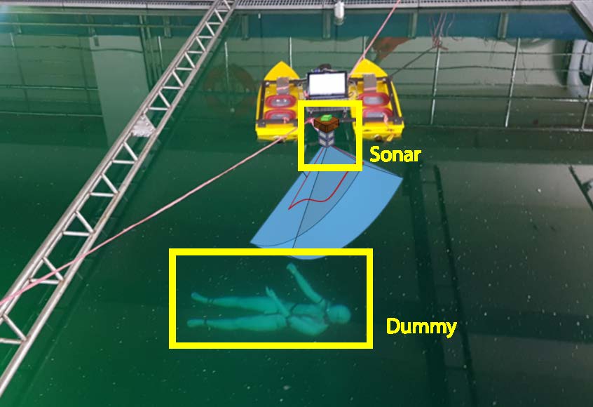
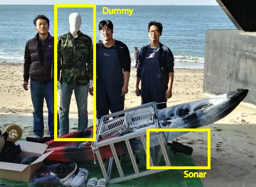
For validation, we used our own dataset listed in the table in Fig. 4(c) together with the publicly available sample images from sonar companies. When collecting our own validation dataset, images were captured by imaging a human-sized dummy using a Teledyne BlueView M900-90, a multibeam imaging sonar with a 90∘ field of view, 20∘ beam width and maximum range. Data were collected from a water tank and from the sea as shown in Fig. 4.

The first dataset, called POOL, was captured in the very clean water testbed of the KIRO (KIRO). The maximum depth of this water testbed was approximately . The dummy was positioned in a water depth of about to simulate a submerged body, as shown in Fig. 4(a). The imaging sonar was mounted on a USV platform that was capable of rotating the sonar sensor at an angular interval of 5∘ and enabled collection of underwater sonar images from various angles. The second dataset (SEA) was captured in severely turbid water from Daecheon Beach in Korea. The BlueView M900-90 was fixed to the lower part of the kayak, as shown in Fig. 4(b), and the heading direction was mounted at about 30∘ downward from the water’s surface. In this experiment, the distance between the sensor and the dummy was about 2 to 4 meters. The SEA dataset was collected twice, and the datasets were named SEA2017 and SEA2018. The dataset of POOL, SEA2017 and SEA2018 has 735, 1045, and 1935 images containing a submerged body respectively.
Fig. 5 illustrates the sample images captured from each environment. Images from water tank reveals relatively darker images than sea trial. The appearance of the target object change drastically even when captured in the same environment depending on the viewpoint and nearby sediment condition. As can be seen SEA2018 presents a brighter image than SEA2017 capturing the target object farther than previous data.
IV-B Experimental Setup and Evaluation criteria


Style transfer and object detection training was performed running on one NVIDIA GTX 1080. Adam optimizer was used. The learning rates were set to with an exponential decay. Weight decay, and were set to , and , respectively.
We considered detection IOU (IOU) larger than 0.25 as the correct detection. For terrestrial images, IOU is often used. Considering sonar images resolution and underwater navigation accuracy, we alleviated criteria of the detection IOU. We think, however, if the targeting sonar images are high resolution such as SAS different IOU can be used as the detection criterion.
IV-C Style Transfer Performance
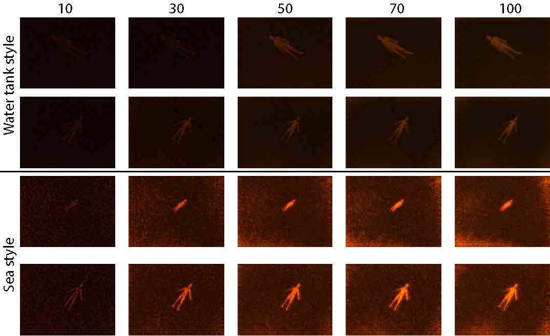
We first validated the effect of the style transfer on performance. By using a style bank, multiple aspects of the images can be synthesized. Using the base input image from the simulator, synthetic images were generated for POOL and SEA2017. The style transferred images are as given in Fig. 6. As can be seen in the figure, the original color map images are style transferred to water tank and sea styles. The style transfer results by epoch are also given in Fig. 7. The chosen target object evolves to be a cleaner, stronger object as the epoch increases.
We also validates the performance of the style transfer when generating and testing for two different target environments. Using simulator-created images, we style transferred to water tank style and sea style. Original 370 SIM-POOL and 370 SIM-SEA2017 were trained with their augmented images and tested over 735 POOL and 1045 SEA2017 images. These style transferred images from each environment were then trained and tested with real data from each case, as in Fig. 8. Both test cases present training from styled images resulting in meaningful object detection performance. Average precision of for POOL and for SEA2017 are achieved. The accuracy when testing in a water tank is higher than when testing at sea. This is because the noise induced from the background sediment is lower when testing in a water tank, as can be seen in sample images in Fig. 5.
IV-D Simulation Training Evaluation


| Name | manufacturer | Image # | Target object | Range [m] | Sonar type |
|---|---|---|---|---|---|
| T1 | Teledyne (P900-45) | 5 | Diver standing sea floor | 5 | Multibeam imaging sonar |
| T2 | Teledyne (P900-130) | 5 | Diver swimming near sea floor | 10 | Multibeam imaging sonar |
| T3 | Teledyne (P900-45) | 5 | Diver swimming far | 10 | Multibeam imaging sonar |
| T4 | Teledyne (P900-45) | 5 | Diver swimming near | 2 | Multibeam imaging sonar |
| T5 | SonarTech | 10 | Diver approaching to sensor | 1-25 | Multibeam imaging sonar |
| T6 | SonarTech | 10 | Diver swimming in-Water | 10 | Multibeam imaging sonar |
| T7 | SonarTech | 5 | Diver standing sea floor | 3 | Multibeam imaging sonar |

If possible, training from the real sea and testing with real sea images would be ideal. Hence, we use the object detection results trained from SEA2017 and tested them on SEA2018 as the baseline, considering that this would be the optimal training method. As can be seen in Fig. 9, the baseline provides around 0.65 accuracy when detecting the object.
In comparison to this baseline, we performed object detection from three cases: when trained from a water tank (735 images from POOL), when trained from stylized images from a water tank (370 images from SIM-POOL) and when trained from simulator using style transfer (370 images from SIM-SEA2017). The precision-recall curve comparison is provided in Fig. 9. The accuracy and detection performance are slightly degraded compared to training from real sea data. On the other hand, the proposed method elaborated the simulation-generated images to include characteristics of the real sea images via style transfer. The resulting object detection performance is comparable to that of the detection result when trained with real sea images.
IV-E Validation to Public Data
Lastly, we verified that the proposed method is applicable to other types of sonar from two different manufacturers by testing in the various environments. Again, we trained the network using the simulator-generated images and by applying style transfer. As described in Fig. 10, we collected sample images from various sample videos. These images contain either a standing or swimming diver at various ranges. The sample data were collected using different sensors and from different sediment conditions. An object’s relative size within an image varies when captured at close (T4) vs far range (T5). Depending on the viewing angle and diver’s posture, a strong shadow occurred when the diver was standing on the sea floor (T1 and T7). When the target is swimming in water, the ground appears separately, as in T3 and T5.
Sample test results are shown in Fig. 11. Despite the variety of sample cases, the target object (i.e., diver in the sea) was successfully detected. One notable case was found in T5 when a diver approached the sonar starting from away from the sensor. As can be seen in the sample and result cases, only a couple of pixels indicate the object. The learned network suffered from this subtle information and detected the object only when the range became closer (less than ). Also, when the target object was found in multiple pixels within a short range, the object was found multiple times when diver motion was greater. The motion could be highly diverse when the diver was swimming and this level of ambiguity was well secured by the training. Furthermore, the trained network was not fooled by other objects such as rocks or the ground, which also appear as bright objects in the scene.
V Conclusion
In this paper, we applied CNN-based underwater object detection from sonar images. The main objective was to overcome data limitations in the underwater environment by synthesizing sonar images obtained from a simulator and testing over sonar images captured in a real underwater environment. Our results validate that the proposed image synthesizing mimics real underwater images without actual performing dives. The proposed training solution is applicable for various target detection by using a 3D model of the target from the simulator.
References
- Cho et al. [2015] H. Cho, J. Gu, H. Joe, A. Asada, and S.-C. Yu, “Acoustic beam profile-based rapid underwater object detection for an imaging sonar.” Journal of Marine Science and Technology, vol. 20, no. 1, pp. 180–197, Mar 2015.
- Purcell et al. [2011] M. Purcell, D. Gallo, G. Packard, M. Dennett, M. Rothenbeck, A. Sherrell, and S. Pascaud, “Use of remus 6000 auvs in the search for the air france flight 447,” in Proceedings of the IEEE/MTS OCEANS Conference and Exhibition, Sept 2011, pp. 1–7.
- Reed et al. [2003] S. Reed, Y. Petillot, and J. Bell, “An automatic approach to the detection and extraction of mine features in sidescan sonar,” IEEE Journal of Oceanic Engineering, vol. 28, no. 1, pp. 90–105, Jan 2003.
- Belcher and Lynn [2000] E. O. Belcher and D. C. Lynn, “Acoustic near-video-quality images for work in turbid water,” Proceedings of Underwater Intervention, vol. 2000, 2000.
- Lee et al. [2013] Y. Lee, T. G. Kim, and H. T. Choi, “Preliminary study on a framework for imaging sonar based underwater object recognition,” in 2013 10th International Conference on Ubiquitous Robots and Ambient Intelligence (URAI), Oct 2013, pp. 517–520.
- Williams and Groen [2011] D. P. Williams and J. Groen, “A fast physics-based, environmentally adaptive underwater object detection algorithm,” in Proceedings of the IEEE/MTS OCEANS Conference and Exhibition, June 2011, pp. 1–7.
- Galceran et al. [2012a] E. Galceran, V. Djapic, M. Carreras, and D. P. Williams, “A real-time underwater object detection algorithm for multi-beam forward looking sonar,” IFAC Proceedings Volumes, vol. 45, no. 5, pp. 306–311, 2012.
- Lee [2017] S. Lee, “Deep learning of submerged body images from 2d sonar sensor based on convolutional neural network,” in Underwater Technology (UT), 2017 IEEE, 2017, pp. 1–3.
- Shin et al. [2015] Y.-S. Shin, Y. Lee, H.-T. Choi, and A. Kim, “Bundle adjustment from sonar images and SLAM application for seafloor mapping,” in Proceedings of the IEEE/MTS OCEANS Conference and Exhibition, Washington, DC, Oct. 2015, pp. 1–6.
- Johnnsson et al. [2010] H. Johnnsson, M. Kaess, B. Englot, F. Hover, and J. J. Leonard, “Imaging sonar-aided navigation for autonomous underwater harbor surveillance,” in Proceedings of the IEEE/RSJ International Conference on Intelligent Robots and Systems, 2010.
- Inc. [2018] S. M. T. Inc., “Navigator,” 2018. [Online]. Available: http://www.sharkmarine.com/
- Galceran et al. [2012b] E. Galceran, V. Djapic, M. Carreras, and D. P. Williams, “A real-time underwater object detection algorithm for multi-beam forward looking sonar,” IFAC Proceedings Volumes, vol. 45, no. 5, pp. 306 – 311, 2012.
- Zhou and Chen [2004] X. Zhou and Y. Chen, “Seafloor sediment classification based on multibeam sonar data,” Geo-spatial Information Science, vol. 7, no. 4, pp. 290–296, 2004.
- Williams [2015] D. P. Williams, “Fast unsupervised seafloor characterization in sonar imagery using lacunarity,” IEEE Transactions on Geoscience and Remote Sensing, vol. 53, no. 11, pp. 6022–6034, 2015.
- Zhu et al. [2017] P. Zhu, J. Isaacs, B. Fu, and S. Ferrari, “Deep learning feature extraction for target recognition and classification in underwater sonar images,” in Proceedings of the IEEE Conference on Decision and Control, 2017, pp. 2724–2731.
- Williams [2016] D. P. Williams, “Underwater target classification in synthetic aperture sonar imagery using deep convolutional neural networks,” in Proceedings of the International Conference Pattern Recognition, Dec 2016, pp. 2497–2502.
- Kim et al. [2016] J. Kim, H. Cho, J. Pyo, B. Kim, and S.-C. Yu, “The convolution neural network based agent vehicle detection using forward-looking sonar image,” in Proceedings of the IEEE/MTS OCEANS Conference and Exhibition, 2016, pp. 1–5.
- McKay et al. [2017] J. McKay, I. Gerg, V. Monga, and R. G. Raj, “What’s mine is yours: Pretrained CNNs for limited training sonar ATR,” in Proceedings of the IEEE/MTS OCEANS Conference and Exhibition, 2017, pp. 1–7.
- Denos et al. [2017] K. Denos, M. Ravaut, A. Fagette, and H. Lim, “Deep learning applied to underwater mine warfare,” in Proceedings of the IEEE/MTS OCEANS Conference and Exhibition, 2017.
- Chen and Summers [2016] J. L. Chen and J. E. Summers, “Deep neural networks for learning classification features and generative models from synthetic aperture sonar big data,” The Journal of the Acoustical Society of America, vol. 140, 2016.
- Dhurandher et al. [2008] S. K. Dhurandher, S. Misra, M. S. Obaidat, and S. Khairwal, “Uwsim: A simulator for underwater sensor networks.” Simulation, vol. 84, no. 7, pp. 327–338, 2008.
- Gwon et al. [2017] D.-H. Gwon, J. Kim, M. H. Kim, H. G. Park, T. Y. Kim, and A. Kim, “Development of a side scan sonar module for the underwater simulator,” in Proceedings of the International Conference on Ubiquitous Robots and Ambient Intelligence, Jeju, S. Korea, Aug. 2017, pp. 662–665.
- Chen et al. [2017] D. Chen, L. Yuan, J. Liao, N. Yu, and G. Hua, “Stylebank: An explicit representation for neural image style transfer,” CoRR, vol. abs/1703.09210, 2017.
- Johnson et al. [2016] J. Johnson, A. Alahi, and L. Fei-Fei, “Perceptual losses for real-time style transfer and super-resolution,” in Proceedings of the European Conference on Computer Vision. Springer, 2016, pp. 694–711.
- Fan et al. [2017] Y. Fan, S. Lyu, Y. Ying, and B.-G. Hu, “Learning with average top-k loss,” in Advances in Neural Information Processing Systems Conference, Long beach, USA, Nov. 2017.
- Goodfellow et al. [2014] I. J. Goodfellow, J. Pouget-Abadie, M. Mirza, B. Xu, D. Warde-Farley, S. Ozair, A. Courville, and Y. Bengio, “Generative adversarial networks,” in Advances in Neural Information Processing Systems Conference, Montreal, CANADA, Nov. 2014.
- Ren et al. [2017] S. Ren, K. He, R. Girshick, and J. Sun, “Faster r-cnn: towards real-time object detection with region proposal networks,” IEEE Transactions on Pattern Analysis & Machine Intelligence, no. 6, pp. 1137–1149, 2017.
- Zitnick and Dollár [2014] C. L. Zitnick and P. Dollár, “Edge boxes: Locating object proposals from edges,” in European conference on computer vision, 2014, pp. 391–405.
- Uijlings et al. [2013] J. R. Uijlings, K. E. Van De Sande, T. Gevers, and A. W. Smeulders, “Selective search for object recognition,” International journal of computer vision, vol. 104, no. 2, pp. 154–171, 2013.
- Girshick [2015] R. Girshick, “Fast r-cnn,” in Proceedings of the IEEE international conference on computer vision, 2015, pp. 1440–1448.