Further author information: (Send correspondence to R.J.H)
E-mail: rharris@lsw.uni-heidelberg.de
Website: https://www.lsw.uni-heidelberg.de/projects/NAIR/cmsms/
NAIR: Novel Astronomical Instrumentation through photonic Reformatting
Abstract
The project ”Novel Astronomical Instrumentation based on photonic light Reformating” is a DFG-funded collaboration to exploit the recognized potential of photonics solutions for a radically new approach to astronomical instrumentation for optical/infrared high precision spectroscopy and high angular resolution imaging. We present a project overview and initial development results from our Adaptive Optics-photonic test bed, Ultrafast Laser Inscribed waveguides for interferometric beam combination and 3D printing structures for astronomical instrumentation. The project is expected to lead to important technological breakthroughs facilitating uniquely functionality and technical solutions for the next generation of instrumentation.
keywords:
Astrophotonics, Spectroscopy, Interferometry, Aperture masking, Integrated optics, Waveguide, Photonic Lantern, Image slicing1 Introduction
Photonic reformatting can be defined as an instrumental technique that utilizes photonic components to improve performance through a spatial rearrangement or reformatting of the distribution of starlight collected by an astronomical telescope, either in the pupil or in the image plane.
In its simpler form, a reformatter is a network of waveguides or fibers used to remap the spatial arrangement of input ports into an equivalent number of output ports. Examples are fiber networks used in Multi Object Spectroscopy (MOS) [1] or Integral Field Spectroscopy (IFS) [2] to reformat the fibers sampling the focal plane of the telescope into a pseudo-slit feeding the spectrograph. photonic Lanterns [3] are more advanced forms of reformatters, which are tapered multi-waveguide/fiber devices, that transform an -modes multi-mode (MM) waveguide/fiber into output single-mode (SM) waveguides/fibers with minimal light losses.
Applications of photonic reformatters can be broadly classified according to the coherent or incoherent level of optical field detection required at the output of the device. In this context, incoherent reformatting implies that only the light intensity of the collected signal is measured, whereas coherent reformatting implies that both the amplitude and phase are the measurable quantities.
Coherent reformatters are needed for applications requiring coherent field detection such as high angular resolution astronomy where phase information is crucial. Examples include long-baseline interferometry, sparse aperture interferometry [4] and its improved derivative pupil-remapping interferometry [5]. The paradigmatic examples in the latter case are pupil plane reformatters that use optical-path-equalized waveguides to rearrange light, collected by a 2D array of sub-pupils, into a non-redundantly spaced waveguide array, suitable for multi-axial, interferometric beam combination schemes [6]. In this case, the critical component functionality is the capability to preserve the phase relationship between the light collected by the input sub-pupils.
Applications requiring incoherent optical field detection are most common in spectroscopy. To this category belong components like 1) mode scramblers [7] and 2) photonic reformatters [8], both based on the PL concept [3]. In these cases, the function of the reformatter is to 1) reduce the modal noise in a MM fiber-fed spectrograph through a rapid and efficient phase scrambling of the output modes of the output MM fiber, 2) increase the intensity scrambling of characteristics, thereby reducing the generation of spurious spatial distributions (”print through”), and 3) reformat the input 2D MM light distribution into a 1D pseudo-slit featuring a diffraction limited profile in the dispersion direction of the spectrograph.
In these cases, loss of the phase information contained in the input field of the device is crucial to achieve a uniform, time-averaged point spread function (PSF) of the spectrograph, as required by high-resolution spectroscopic applications.
We break our project up into three of areas of work, these are listed below:
Sparse aperture interferometry: Pioneered at optical and infrared wavelengths by Ref. 4 and 9, aperture masking treats the primary mirror as multi-aperture non-redundant interferometer that measures the visibilities and the closure phases, from which an image can be reconstructed. Non-redundancy of the sub-array is essential to recover an unperturbed estimate of the phase of the object at given spatial-frequency. This technique has produced astrophysical images with exquisite fidelity and /(2) resolution ( being the maximum baseline of the sub-array), and represents a highly competitive method to retrieve diffraction-limited images with seeing- limited telescopes. A well-known limitation of aperture masking is that it uses only between 1 % and 10 % of the photons, due to constraints imposed by the non-redundancy condition and the coherence length of the atmosphere. This biases the technique to bright sources. In order to avoid wasting a significant fraction of the light entering the telescope, [5] proposed the so-called pupil remapping technique, a derivation of the aperture masking technique. It is based on the use of photonic devices (e.g. a single-mode Fiber (SMF) bundle) to transform or remap the fully redundant input pupil of the telescope into a non-redundant output pupil used to measure interferometric visibilities and closure phases for high-fidelity, high-resolution image reconstruction. In practice, the difficulty of calculating a fully non-redundant pupil for more than 15 sub-apertures and the large number of required encoding pixels (with consequent high readout noise) has limited the efficiency of this approach to bright sources, partly because of the poor mechanical stability of fibers at visible wavelengths [10]. With the recent progress made in interferometric integrated optics beam combining devices, new designs based on multi-combiner concepts as studied in Ref. 11 can be implemented to extend sparse aperture interferometry to the full pupil.
Photonic reformatters: To achieve higher spectral resolving power the input fibers to spectrographs are frequently sub-divided by an image slicer. This allows an increase of spectral resolution, but requires another optical element, which reduces throughput and increases complexity. We propose to reformat the shape of the fiber within the fiber, which simplifies the alignment process and potentially increases throughput. Several different shapes for reformatters have been proposed and trialled (e.g. Ref. 12, 13, 14). We will concentrate on those that reformat the PSF into a long slit in a similar way to conventional spectrographs. This allows for ease of retrofitting to conventional spectrographs if required. In addition to reformatting we will trial SM (diffraction-limited) slits. These are diffraction limited in the dispersion direction, potentially removing the problem of modal noise in the spectra. However whether this is the case still needs to be proven, so the project will be a great addition to this.
Scrambling Fibers: Precision spectroscopy in astronomy, such as exoplanet detection by precision radial velocity measurement techniques, is a rapidly developing area of astronomical research, and there is a strong drive to detect habitable Earth size planets. There are several new precision spectroscopy facilities under development or recently completed, e.g. ESPRESSO [15], PEPSI [16], CARMENES [17, 18] and SPIRou [19]. Some of these instruments operate in the near-infrared (NIR) band (e.g. ELT-HIRES, [20] for the Extremely Large Telescope (ELT), GIANO [21] for TNG and HZPF [22] for HET) and are designed to determine radial velocity shifts of the order of 1 m/s or less. This not only requires a very stable spectrograph but also (if fiber fed) a very stable fiber feed. However, MM optical fibers suffer from modal noise and this has been shown to critically limit the signal-to-noise ratio achievable in fiber-coupled, high-resolution spectrographs. Because modal noise scales with increasing wavelength (i.e. decreasing mode numbers), it represents a limitation for the current and next generation of near-infrared precision radial velocity spectrographs. The scrambling fiber development that we are proposing, based on the multi-core Fiber (MCF) and PL technologies [7], aims at significantly improving scrambling and reducing modal noise in the optical fibers linking both the telescope and precision calibration system to the spectrograph, thus boosting the performance of future instruments.
The Novel Astronomical Instrumentation based on photonic light Reformating (NAIR) consortium aims to develop reformatting in all the described areas. Our project was funded in January 2017 by the Deutsche Forschungsgemeinschaft (DFG) and in this paper we summarize the work performed so far. In Section 2 and 3 we report on the initial coherent and incoherent results. In Section 4 we discuss our future work and conclude in Section 5.
2 Work on coherent reformatting devices
The combination of multiple beams within an integrated optics chip has proven to be an efficient solution in the context of both long baseline interferometry [23] as well as aperture masking interferometry [6]. Besides their small footprint, SM waveguides naturally operate as a spatial filter leading to a well-defined instrumental transfer function. As a consequence, integrated optics couplers allow the measurement of interferometric visibilities with a much higher accuracy than conventional bulk optics solutions. However, the coherent on-chip combination poses sensitive requirements in terms of differential dispersion and polarization properties and needs to compete with the high throughput of classical bulk optics. Our research efforts in this field concentrate on innovative on-chip beam combination schemes such as reformatters and discrete beam combiners as well as exploring new materials to access the 3-5 m range.
2.1 Integrated 4- Telescope coherent Reformatters
Coherent Reformatters are specially designed waveguides that rearrange between one set of positions and another whilst retaining the same path length. The tolerance required for the path length difference depends on the observing wavelength as the Fried parameter describing the atmospheric turbulence depends on . The construction of these reformatters or special waveguides is motivated by Ref. [24] using spline technique. These spline waveguides had been successfully implemented in the second generation Dragonfly instrument to achieve experimental throughputs of 70 % at the output of the waveguides [25].
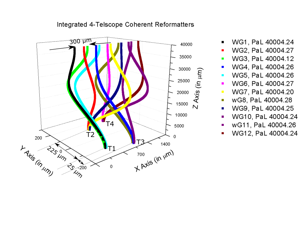
Fig. 1a shows the design of a 3D reformatter created using spline technique, it is similar to the idea of pairwise beam combination [26]. The planar design had unnecessary waveguide crossings that gave to undesirable cross-talk and we believe that it can be mitigated using 3D geometry. Light from 4 telescopes is injected at the input of a single chip and are divided by tri-couplers arranged in a triangular geometry. These are then combined interferometrically giving 6 pairs, a total of 12 outputs. The outputs from the pairwise waveguides can be combined in free-space or using integrated beam combination mechanism on the same chip to retrieve the complex visibilities. The input position for the 4 telescopes are offset by 25 m and the 6 pairwise outputs of the waveguides are kept at a period of 300 m to minimize the amount of stray light. The coherence length of the photons under turbulent atmosphere at 3.4 m is roughly 30 m [6]. Hence, for our case as seen from Fig. 1a, it is sufficient to have path length difference, of 0.1 m between all the pairs of waveguides.
We evaluated the performance of these spline waveguides using BEAMPROP in RSOFT. We used a step index profile with = 2.315, = 2.31 and a channel waveguide geometry of 8.5 m 17 m that is SM at of 3.4 m[27, 28]. We measured the output of all spline waveguides and normalized it w.r.t a straight waveguide. We can see from Fig. 1b that the average power of all waveguides within a certain discrepancy is around -0.08 dB that leads to theoretical normalized throughput of 98%. Our model does not include material dispersion and the minimum radius of curvature for all the waveguides was more than 1000 mm due to the device length of 40 mm. Our study also showed that the throughputs dropped by more than 50% when was 16 mm or when the length of the device was 25 mm for the same configuration. Hence, for the proposed geometry there were minimal bend and transition losses and the throughput of these waveguides was much higher in simulations. This will not be the case when practical devices will be fabricated using ultrafast laser inscription (ULI) [29] and will need to be addressed in the future.

2.2 Discrete beam combiners
We are investigating novel beam combination schemes that go beyond the classical 2x2 or ABCD couplers [26]. In particular, we focus on so-called DBCs [27] in which a large set of evanescently coupled waveguides produces an interferometric output pattern from which the mutual visibilities of the input beams can be derived. Mathematically, the relationship between the input visibilities and the output intensity pattern is described by the visibility-to-pixel-matrix (V2PM) [30]. The quantities of interest, i.e. the mutual coherence functions of the input beams, can be obtained by measuring the output patterns and applying the inverse V2PM (then called pixel to visibility matrix (P2VM)). The challenge is to obtain a DBC configuration for which this problem is well conditioned, i.e. insensitive to small errors in the intensity measurements.
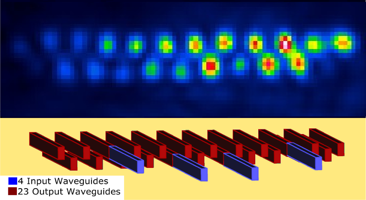
A promising realization of a DBC is the so-called zig-zag array, see Fig. 5b. Such a configuration was tested with monochromatic light at 1.30, 1.50 and 3.39 m. The advantage of this type of beam combiner is that it does not require any bends in the waveguides and therefore eliminates any bend losses. Naturally, any device based on evanescent coupling exhibits chromatic behavior. Therefore, also the V2PM of the zig-zag array is expected to be chromatic. We are currently working on the first characterizations with broadband light to progress towards a first on-sky demonstration.
2.3 6- Telescope discrete beam combiner for the H band
We have manufactured 6-telescope discrete beam combiners in Gallium–Lantanum–Sulfide (GLS) using ULI. The combiners were manufactured to demonstrate the performance of components that could be hosted at current interferometric facilities, although for the NAIR project we only use 4-input beam combiners. Since the ULI manufacturing process requires several steps of calibration we have manufactured a test facility that permits the characterization of a beam combiner of 6-telescope complexity in a couple of minutes per wavelength. We then use a tunable laser to characterize the beam combiner across the whole bandwidth.
2.3.1 Automated J and H band DBC characterization bench
.
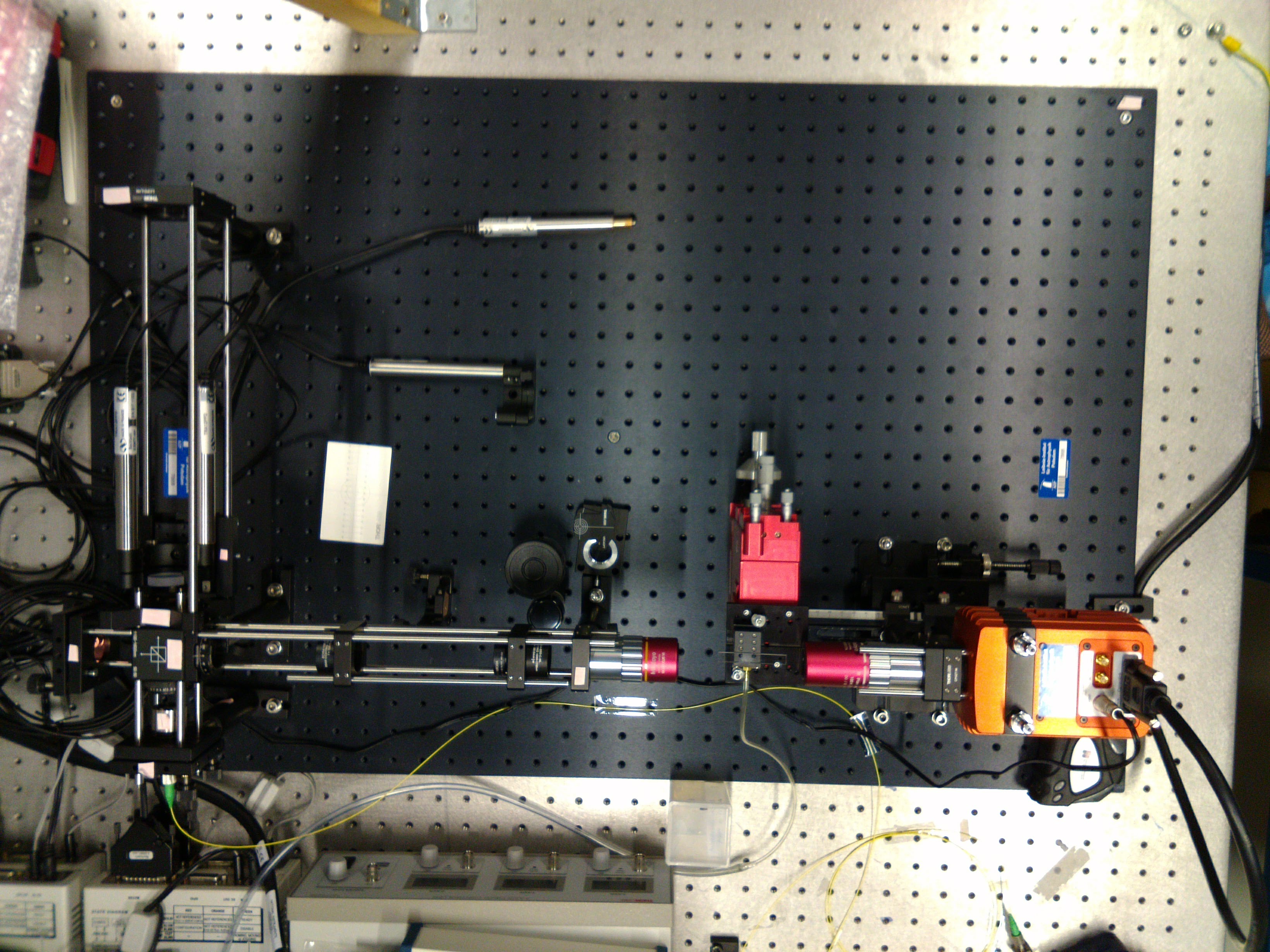
The beam combiners were characterized on our automated test rig at Potsdam using a two-beam Michelson interferometer capable of injecting two beams through a direct and a delayed pathway. The chromatic response of the component can be characterized using two separate tunable laser sources: one at 1.3 m and one at 1.5 m. The beam from the tunable source is split using a beam splitter and directed to two kinematic mounts. The mounts can be steered using stepper motors controlled by a computer through a serial link and can address the different inputs of the component. The test bench and a map of the inputs of the components are shown in Fig. 2a and Fig 3.

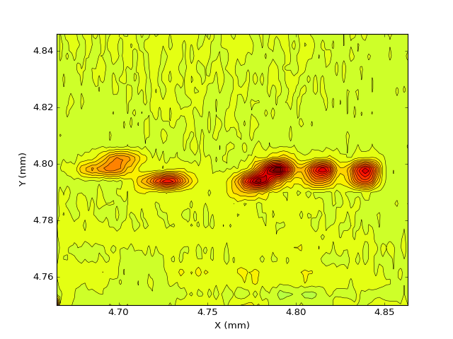
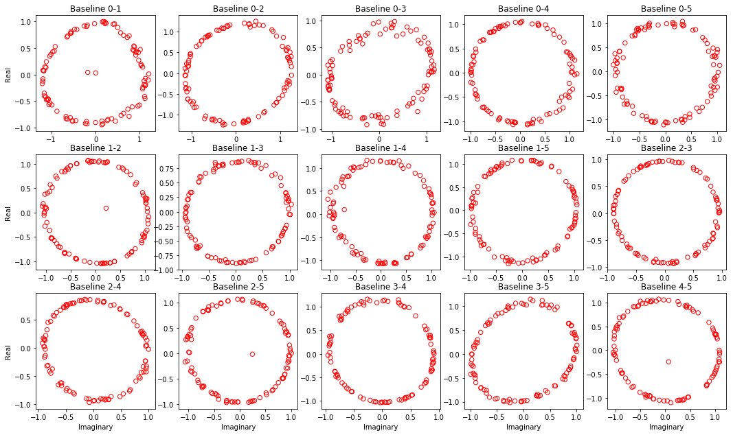
The inputs of the component are automatically found by performing a raster scan using the stepper motors and measuring the integrated intensity from the outputs. A map of the intensity is then built and the outputs found. Once we have the positions of the inputs for the two beams we can build the V2PM matrix[30]. One beam only is injected and all the outputs recorded by the camera. The procedure is repeated for all six beams. This gives us a measurement of the photometry of the inputs. Two beams are then injected and a USB-controlled delay line scanned with steps that are 1/10 of the laser wavelength in use. An image is acquired for each step. Sine and cosine quadratures are then fitted to the data to extract the real and imaginary part of the interfering fields. This values are placed in the V2PM matrix together with the photometry. After the V2PM matrix is filled up it can be inverted to give the P2VM that relates the output recorded from the camera to the complex visibilities. Fig. 4 shows the real and imaginary part of 15 visibilities obtained injecting two beams in the combiner for all possible baselines.
2.4 Exploring integrated optics beyond 3 microns
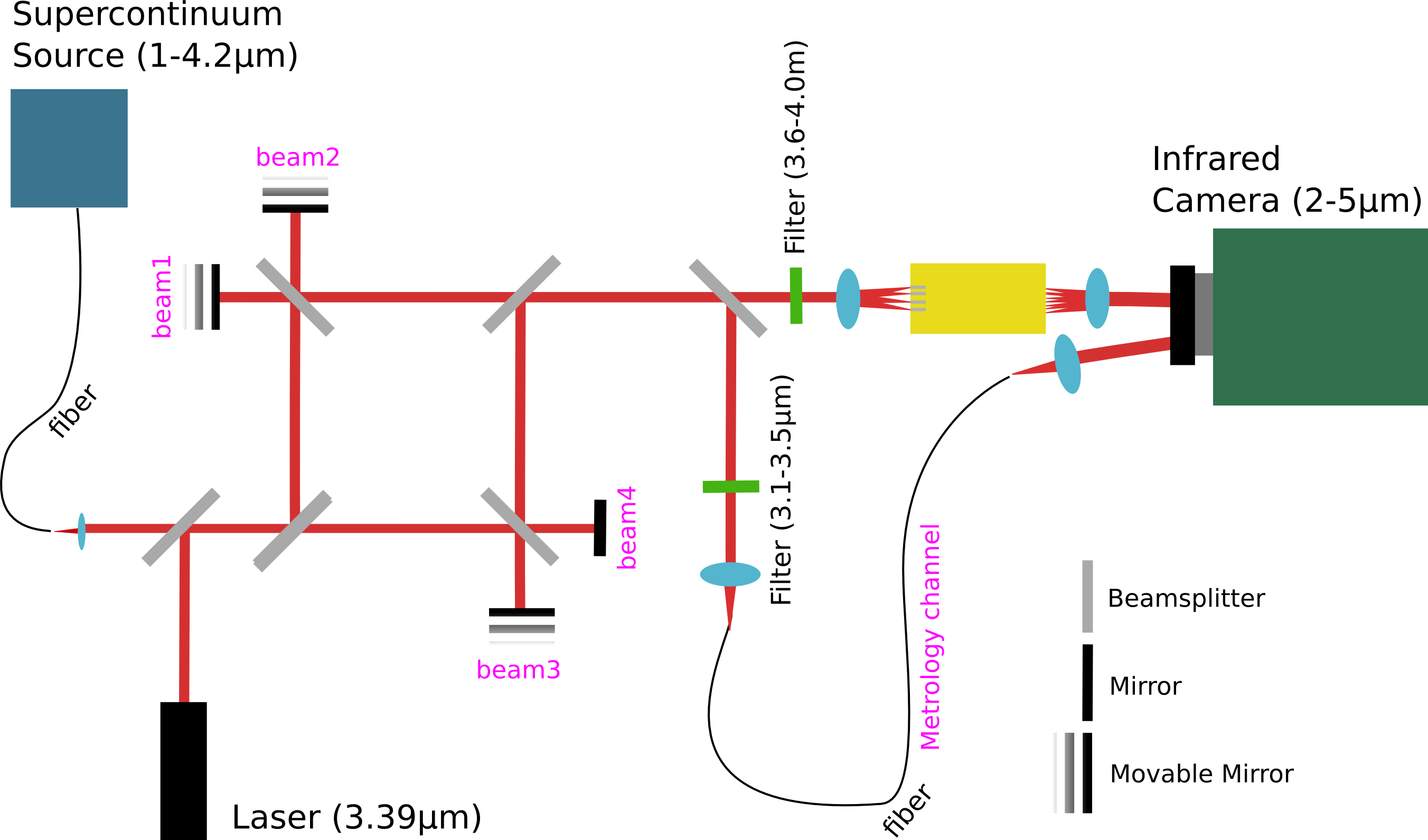
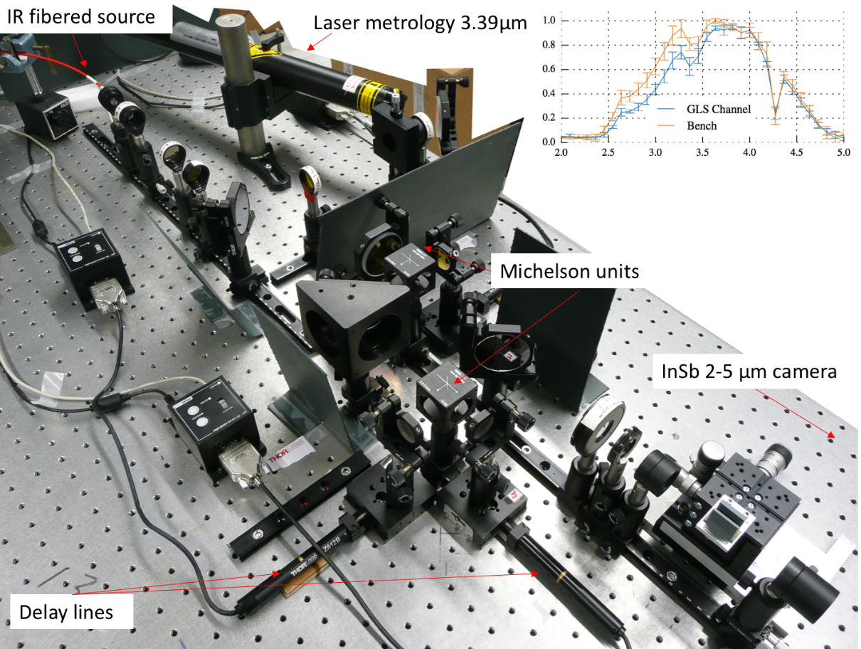
In the context of NAIR, the thermal infrared designates the spectral region where cryogenic instruments are required to mitigate the thermal background that would otherwise hamper any meaningful astrophysical observations. As these cryogenic instruments need to be placed in a large evacuated enclosure, they have a high cost, because of this the implementation of small scale integrated optics instruments quickly becomes an important parameter of any trade-off study. In parallel to the work conducted in the J and H bands, in NAIR we explore solutions to cover the K (2.2 m) and L/M (3-5 m) bands leading to a unique wavelength coverage, in particular for astrophysical studies in the field of star and planet formation. To this end, we have set up a dedicated testbench to characterize components in these wavelengths ranges, see Fig. 5a.
These solutions are based on the processing of infrared glasses, transparent beyond the spectral range of the well-researched silica platform. To this end, we are experimenting with the use of ULI [31, 32, 33] in mid-IR transparent materials such as GLS and ZBLAN in order to manufacture coherent reformatter and 4-telescope beam combiners. This work is partially based on the heritage of the Advanced Laser Writing for Stellar interferometry (ALSI) project[34], where we demonstrated the feasibility and adequate performances of laser-written integrated optics directional couplers for broadband interferometry in the L, L’ and M bands [35, 36]. These devices were based on infrared GLS and ZBLAN glasses[35, 36] and showed a total throughput across the band of 30 to 60%, respectively, including Fresnel reflections and propagation losses. This result represents a critical step towards the development of the so-called ABCD 4-telescope units, which cascade several couplers in order to retrieve the interferometric visibility and phase. In one arm of the ABCD (see Ref. [26] for details) a localized increase of the refractive index allows us to insert an intrinsic /2 phase shift in order to retrieve the instantaneous interferometric visibility and phase, without the need of scanning an internal delay-line. 2-telescope ABCD units were tested in monochromatic and polychromatic light to assess the performance of the phase-shifting unit [28].
The manufacturing of integrated optics using ULI matches well with our research on the development of Discrete Beam Combiners targeted in NAIR. The ability offered by ULI to inscribe 3D structures is unique for the manufacturing of the zig-zag DBC architecture. As we demonstrated the compatibility of ULI with infrared glasses, the extension beyond the 1.55 m telecom band is quite appealing. Following the first characterization of DBCs at 3.39 m we are improving our understanding of the DBC behavior in polychromatic light. From output images similar to those shown in Fig. 5b, we measure 23 interferograms (1 interferogram per output) for each of the 6 baselines (for a 4-telescope interferometer) from which an instrumental contrast and a relative phase is measured. This calibration phase allows us to derive the P2VM from which a static measurement of the coherence function of the source can be retrieved. The experimental characterization is complemented with a detailed simulation work using RSoft. A key capability here for this part of the work in NAIR is the mid-infrared test bench we have developed in Cologne, and which covers the 2–5 m spectral domain. It is designed to accommodate four beams that can be independently and simultaneously injected in the component. Three independent delay lines that can be scanned at different velocities allow to record temporally multiplexed signals. Finally, laser metrology operating at 3.39 microns allows us to precisely calibrate the optical delay line and to perform Fourier Transform spectroscopy of the different outputs. This will permit us to verify the level of similarity of the spectral content of each of the 23 outputs. A picture of the mid-infrared facility is shown in Fig. 2b.
3 Work on incoherent reformatting devices
This section details with the initial results of the incoherent side of the collaboration, where we are not trying to detect and control the phase of the system, or when we aim to scramble it completely.
The results in this section are based on 3D printed micro lens arrays, modeling of photonic devices and the development and modeling of scrambling fibers.
3.1 Tip-tilt sensing using a 3D printed micro-lens array
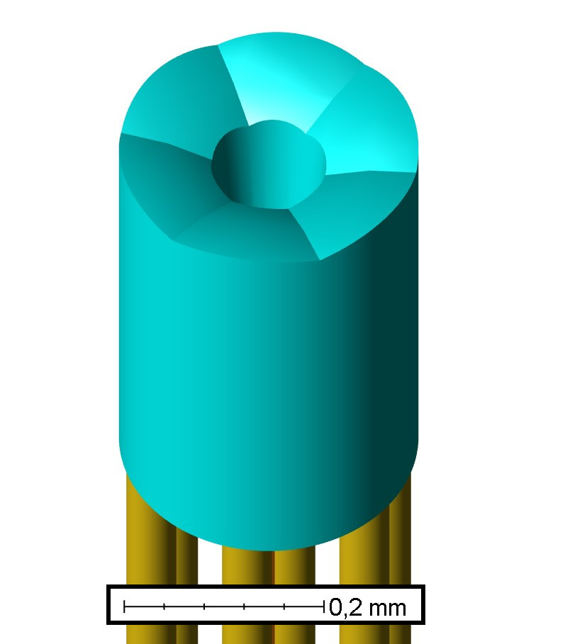
We are also developing an integrated focal plane tip-tilt sensor for SMF coupling. This is creating by printing a free-form micro-lens array (MLA) onto an array of fibers. A first study has shown the feasibility of this approach [37] and we have adapted it in order to fit it to the prototype iLocater fiber coupling instrument at the Large Binocular Telescope (LBT). Our new design consists of a central SMF leading to the science instrument and six surrounding multi-mode Fibers designed for sensing any movement of the incoming telescope beam. The model is shown in Fig. 6a, with cross-sections of the MLA with an incident aligned (Fig. 6b), slightly misaligned (Fig. 6c) and badly misaligned beam (Fig. 6d). The aligned beam is completely coupled into the SMF, while some or most of the light is coupled into the sensing MMF for the misaligned beams. This design allows optimal fiber coupling if the telescope beam is aligned to the central SMF. When the beam is decentered the light will be coupled into the surrounding sensing fibers, allowing correction.
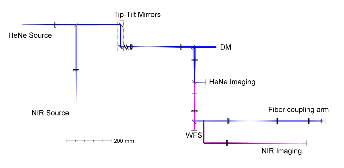
To prepare for on-sky tests, a testbed is also being developed in collaboration with the Max Plank Institute for Astronomy (MPIA), Institute for System Dynmaics Stuttgart (ISYS) and the Landessternwarte (LSW) is using and enhancing an Adaptive Optics (AO) vibration control testbed and is called the Koenigstuhl Observatory Opto-mechatronics Laboratory (KOOL). This testbed will allow the groups to simulate parts of the LBT, including vibration in the system and the beam from the telescope. The optical design of the KOOL system is shown in Fig.7.


3.2 Reformatter Modeling
We have also been working on modeling photonic reformatting devices. We have recently published a modeling comparison with the Photonic Dicer (PD) [39], a device tested on-sky in 2013[8]. Our results matched well with the reported on-sky ones. Furthermore, we improved upon the design, improving the theoretical throughput by 6.4% (which is a 30% improvement in performance) and reducing the slit output movement by 50%, resulting in lower modal noise (see Fig. 8 reproduced from Ref. 39). In addition, an improvement in the calculated value of magnification at the input of the PD [8], highlighting the importance and usefulness of simulations in optimizing the throughput performance. Our study encourages detailed simulations that prove to be a valuable tool for the design of new components for astronomy, enhancing the precision and the efficiency of them in realistic atmospheric conditions.
In this conference we will also show preliminary results from the modeling of the Hybrid reformatter [40], which compliment the reported results in literature.


3.3 Scrambling
Our collaboration aims to understand and improve the scrambling and modal noise properties of the PL, in order to better stabilize their use with spectrographs. To do this we have performed the modeling detailed below.
The traditional concept of a PL is a device in which a series of SM waveguides interfaces to a MM waveguide [41]. A common method of fabricating PLs is to thermally taper a MCF. The PL taper transition is such that the SM cores of the multi-core fiber become too small to guide light resulting in the cladding material containing the small residual SM cores to form the core of the MM section of the PL. Although the tapered SM cores may be too small to act as individual light guides, the remaining residual core refractive index profile does not disappear completely and therefore has to be considered when measuring the performance. The remaining residual SM cores slightly increase the average refractive index of the MMF core thereby increasing the Numerical Aperture (NA) of the MM PL [42] resulting in a possible mode number mismatch loss at the taper transition. Also the residual SM cores appear to influence the intensity distribution across the MM PL core, which is an effect that needs to be fully understood in order to optimize the performance of the current MCF PL fiber scrambling devices [43].
Fig. 9 shows a measured 2D refractive index profile of MM port of a 120 core MCF PL. The measurement was performed using an Interfiber Analysis IFA-100 instrument. The refractive index profile of the residual SM cores can clearly be seen as the hexagonally positioned red/orange spots within the yellow MM core.

In order to test the effect of residual SM cores on light propagation through the PL, a set of simulations were run with and without these cores. A 37 core PL was modeled, composed of a MM section of length 4500 m and the SM section of 8000 m. The MM section included a 46.1327 m diameter core ( = 1.4440) surrounded by a cladding ( = 1.44310). The SM section contains 37 tapered cores ( = 1.45397) with a maximum diameter of 6.50 m at the furthest point from the MM section. The SM section uses the = 1.4440 MM core material as the cladding for the SM cores, with the cores themselves increasing in size until they are large enough to guide light propagation. In the first simulation, the SM cores taper up from 0 m to 6.50 m, and the MM core is homogeneous. In the second, 37 residual cores of 1.339 m diameter were included in the MM core, with the SM cores tapering up from this diameter.
The simulation was run by launching a Gaussian spot with a Full Width at Half Maximum (FWHM) of 8 m and a 1.550 m wavelength into the MM end of the PL. The spot was launched at a 15 m offset from the center of the fiber to better observe the transverse behavior of the propagating light.
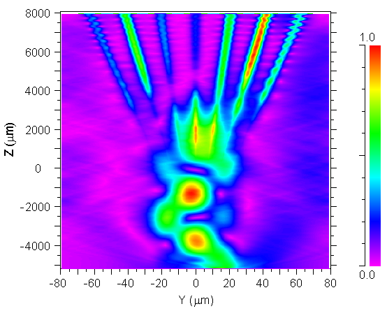
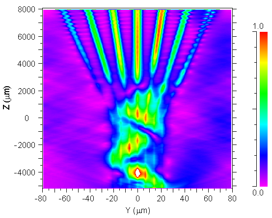
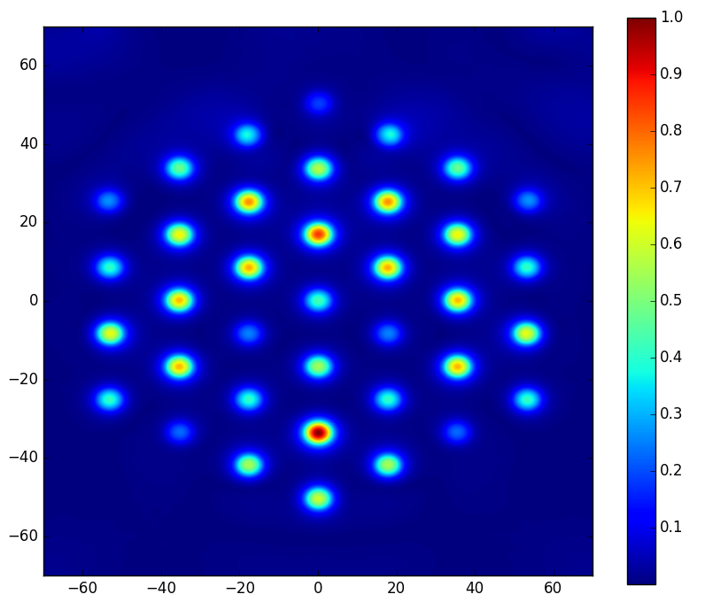
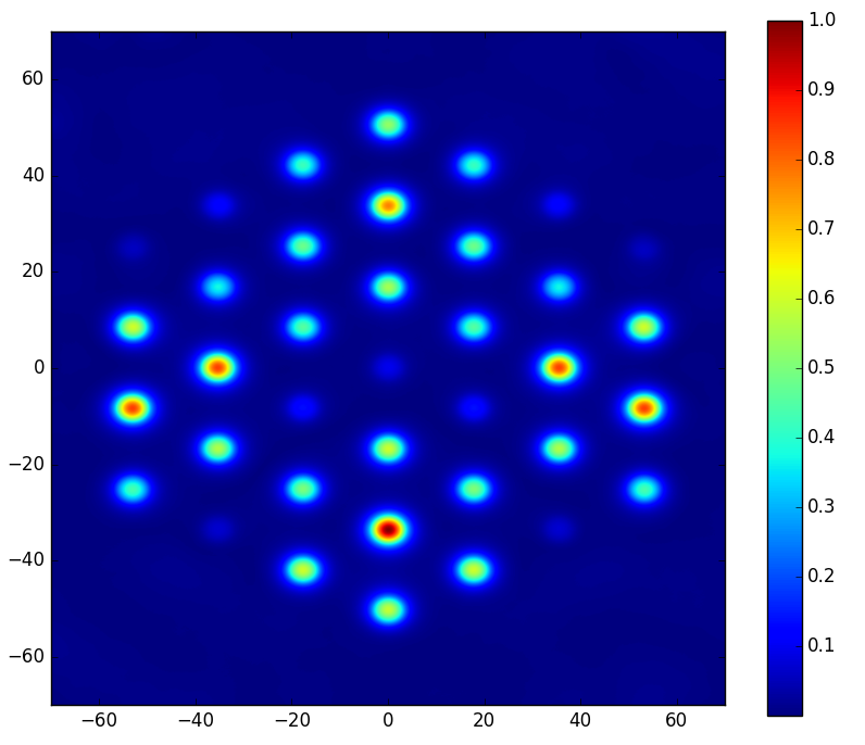
Fig. 10a shows light propagating along the MM section section of the PL by total internal reflection as would be expected. When it reaches the transition region between the MM and the SM sections, light is coupled into SM depending on the modal distribution at that point. Figure 11a shows the resulting SM distribution, although it should be noted that this distribution is heavily dependent on factors such as fiber length and curvature which affect the modal distribution at the transition region.
Fig. 10b shows the light propagation along the PL including the residual cores. In the MM section, light propagates with a fairly similar distribution, but an increase in intensity at the residual cores can clearly be seen and the general distribution is slightly altered. In the SM section, the distribution is significantly altered, confirmed by Fig. 11b. It can therefore be concluded that residual cores in the MM section of a PL caused by insufficient mixing when fusing SM fibers cannot be ignored, and theoretical and must be considered. The small change in light propagation along the MM section has a significant effect on the modal distribution at the transition region, which in turn significantly effects the SM intensity distribution.
4 Future work
With just over a year and a half left on the first three years of the project (there is potential for another 3 years of funding) we are on track to complete what we want. Our goals for the rest of the project are:
-
•
To fabricate the integrated 4-telescope coherent reformatter in substrate glasses such as Corning Eagle or GLS using ULI. We will then study the deviation from the simple model that we have considered in section 2.2.
-
•
We will also continue to develop the reformatting technologies that we successfully characterized in the lab to the telescope to perform on-sky testing. To this end, we currently investigate potential telescope sites as well the telescope-integrated optics interface.
-
•
KOOL is currently being adapted and will soon be ready for initial tests of our new tip-tilt sensor. Once our system is tested we will utilize it with the prototype fiber feed for the high resolution spectrograph iLocater [44].
-
•
We have now thoroughly tested our reformatter modeling, future work will be to help optimize devices for use on sky.
-
•
The MCF and MCF PL work will continue the parallel detailed development of the theory (via modeling and simulations) and experimental understanding (via laboratory testing of MCF PLs) of the light propagation in such devices, as a function of a large range of optical input and environmental conditions. The overall aim is to improve the design and performance of MCF based PLs with highly effective light scrambling characteristics and as integral components of reformatting devices, for applications in high precision/stability spectroscopy.
5 Conclusions
The ”Novel Astronomical Instrumentation based on photonic light Reformating” project is a collaboration between the Landessternwarte, Heidelberg, The Leibniz Institute for Astrophysics Potsdam and the University of Köln and is funded by the Deutsche Forschungsgemeinschaft. It is developing photonic reformatting technologies for both coherent (namely interferometry) and incoherent (namely spectroscopy) applications that will allow the next generation of astrophotonic instrumentation to function efficiently with large modern telescopes.
We have already made significant developments in modeling of the photonic lantern, reformatting devices and beam combiners. Prototypes of beam combiners, microlens arrays and photonic lanterns are also being tested.
Future work will be to continue these tests and integrate them into the next generation of instrumentation at observational facilities.
Acknowledgements.
This work was supported by the DFG through project 326946494, ’Novel Astronomical Instrumentation through photonic Reformatting’ This publication makes use of data generated at the Königstuhl Observatory Opto-mechatronics Laboratory (short: KOOL) which is run at the Max-Planck-Institute for Astronomy (MPIA, PI Jörg-Uwe Pott, jpott@) in Heidelberg, Germany. KOOL is a joint project of the MPIA, the Landessternwarte Königstuhl (LSW, Univ. Heidelberg, Co-I Philipp Hottinger), and the Institute for System Dynamics (ISYS, Univ. Stuttgart, Co-I Martin Glück). KOOL is partly supported by the German Federal Ministry of Education and Research (BMBF) via individual project grants. This research made use of Astropy, a community-developed core Python package for Astronomy[45], Numpy [46] and Matplotlib [47].References
- [1] J. M. Hill, J. R. P. Angel, J. S. Scott, et al., “Multiple object spectroscopy - The Medusa spectrograph,” Astrophys. J. Lett. 242, L69–L72 (Dec. 1980).
- [2] C. Vanderriest, “A fiber-optics dissector for spectroscopy of nebulosities around quasars and similar objects,” Publications of the Astronomical Society of the Pacific 92(550), 858 (1980).
- [3] S. Leon-Saval, T. Birks, J. Bland-Hawthorn, et al., “Multimode fiber devices with single-mode performance,” Optics letters 30(19), 2545–2547 (2005).
- [4] C. Haniff, C. Mackay, D. Titterington, et al., “The first images from optical aperture synthesis,” Nature 328(6132), 694–696 (1987).
- [5] G. Perrin, S. Lacour, J. Woillez, et al., “High dynamic range imaging by pupil single-mode filtering and remapping,” Monthly Notices of the Royal Astronomical Society 373(2), 747–751 (2006).
- [6] N. Jovanovic, P. G. Tuthill, B. Norris, et al., “Starlight demonstration of the dragonfly instrument: an integrated photonic pupil-remapping interferometer for high-contrast imaging,” Monthly Notices of the Royal Astronomical Society 427(1), 806–815 (2012).
- [7] D. M. Haynes, I. Gris-Sanchez, K. Ehrlich, et al., “New multicore low mode noise scrambling fiber for applications in high-resolution spectroscopy,” in [Advances in Optical and Mechanical Technologies for Telescopes and Instrumentation ], 9151, 915155, International Society for Optics and Photonics (2014).
- [8] R. J. Harris, D. G. MacLachlan, D. Choudhury, et al., “Photonic spatial reformatting of stellar light for diffraction-limited spectroscopy,” Monthly Notices of the Royal Astronomical Society 450(1), 428–434 (2015).
- [9] P. Tuthill, J. Monnier, W. Danchi, et al., “Michelson interferometry with the keck i telescope,” Publications of the Astronomical Society of the Pacific 112(770), 555 (2000).
- [10] E. Huby, G. Perrin, F. Marchis, et al., “First, a fibered aperture masking instrument-i. first on-sky test results,” Astronomy & Astrophysics 541, A55 (2012).
- [11] S. Minardi, L. Labadie, and S. Lacour, “Discrete optical multi-aperture combiner: instrumental concept,” in [SPIE Astronomical Telescopes+ Instrumentation ], 844526–844526, International Society for Optics and Photonics (2012).
- [12] S. G. Leon-Saval, C. H. Betters, and J. Bland-Hawthorn, “The photonic tiger: a multicore fiber-fed spectrograph,” in [Proc. of SPIE Vol ], 8450, 84501K–1 (2012).
- [13] R. Harris, J. Allington-Smith, D. MacLachlan, et al., “A comparison of concepts for a photonic spectrograph,” in [SPIE Astronomical Telescopes+ Instrumentation ], 91474C–91474C, International Society for Optics and Photonics (2014).
- [14] N. Cvetojevic, H. Fernando, N. Jovanovic, et al., “High-resolution integrated photonic micro-spectrographs for radial velocity exoplanet astronomy,” in [The European Conference on Lasers and Electro-Optics ], CH_1_6, Optical Society of America (2013).
- [15] F. A. Pepe, S. Cristiani, R. Rebolo Lopez, et al., “ESPRESSO: the Echelle spectrograph for rocky exoplanets and stable spectroscopic observations,” in [Ground-based and Airborne Instrumentation for Astronomy III ], SPIE Astronomical Telescopes+ Instrumentation 7735, 77350F (July 2010).
- [16] K. Strassmeier, I. Ilyin, A. Järvinen, et al., “Pepsi: The high-resolution échelle spectrograph and polarimeter for the large binocular telescope,” Astronomische Nachrichten 336(4), 324–361 (2015).
- [17] A. Quirrenbach, P. Amado, H. Mandel, et al., “Carmenes: Calar alto high-resolution search for m dwarfs with exo-earths with a near-infrared echelle spectrograph,” in [Ground-Based and Airborne Instrumentation for Astronomy III ], 7735, 773513, International Society for Optics and Photonics (2010).
- [18] A. Quirrenbach, P. Amado, J. Caballero, et al., “Carmenes instrument overview,” in [Ground-based and airborne instrumentation for astronomy V ], 9147, 91471F, International Society for Optics and Photonics (2014).
- [19] S. Thibault, P. Rabou, J.-F. Donati, et al., “Spirou@ cfht: spectrograph optical design,” in [Ground-based and Airborne Instrumentation for Astronomy IV ], 8446, 844630, International Society for Optics and Photonics (2012).
- [20] F. Zerbi, F. Bouchy, J. Fynbo, et al., “Hires: the high resolution spectrograph for the e-elt,” in [SPIE Astronomical Telescopes+ Instrumentation ], 914723–914723, International Society for Optics and Photonics (2014).
- [21] L. Origlia, E. Oliva, C. Baffa, et al., “High resolution near ir spectroscopy with giano-tng,” in [SPIE Astronomical Telescopes+ Instrumentation ], 91471E–91471E, International Society for Optics and Photonics (2014).
- [22] S. Mahadevan, L. W. Ramsey, R. Terrien, et al., “The habitable-zone planet finder: A status update on the development of a stabilized fiber-fed near-infrared spectrograph for the for the hobby-eberly telescope,” in [Ground-based and Airborne Instrumentation for Astronomy V ], 9147, 91471G, International Society for Optics and Photonics (2014).
- [23] Gravity Collaboration, R. Abuter, M. Accardo, et al., “First light for GRAVITY: Phase referencing optical interferometry for the Very Large Telescope Interferometer,” Astronomy & Astrophysics 602, A94 (June 2017).
- [24] N. Charles, N. Jovanovic, S. Gross, et al., “Design of optically path-length-matched, three-dimensional photonic circuits comprising uniquely routed waveguides,” Applied optics 51(27), 6489–6497 (2012).
- [25] B. Norris, N. Cvetojevic, S. Gross, et al., “High-performance 3d waveguide architecture for astronomical pupil-remapping interferometry,” Optics express 22(15), 18335–18353 (2014).
- [26] M. Benisty, J.-P. Berger, L. Jocou, et al., “An integrated optics beam combiner for the second generation VLTI instruments,” Astronomy & Astrophysics 498, 601–613 (May 2009).
- [27] R. Diener, J. Tepper, L. Labadie, et al., “Towards 3d-photonic, multi-telescope beam combiners for mid-infrared astrointerferometry,” Opt. Express 25, 19262–19274 (Aug 2017).
- [28] R. Diener, S. Minardi, J. Tepper, et al., “All-in-one 4-telescope beam combination with a zig-zag array of waveguides,” in [Optical and Infrared Interferometry and Imaging V ], 9907, 990731, International Society for Optics and Photonics (2016).
- [29] A. Arriola, S. Gross, N. Jovanovic, et al., “Low bend loss waveguides enable compact, efficient 3d photonic chips,” Optics express 21(3), 2978–2986 (2013).
- [30] A. Saviauk, S. Minardi, F. Dreisow, et al., “3D-integrated optics component for astronomical spectro-interferometry,” Applied Optics 52, 4556 (July 2013).
- [31] K. M. Davis, K. Miura, N. Sugimoto, et al., “Writing waveguides in glass with a femtosecond laser,” Optics Letters 21, 1729–1731 (Nov. 1996).
- [32] S. Nolte, M. Will, J. Burghoff, et al., “Femtosecond waveguide writing: a new avenue to three-dimensional integrated optics,” Applied Physics A: Materials Science & Processing 77, 109–111 (2003).
- [33] R. R. Thomson, A. K. Kar, and J. Allington-Smith, “Ultrafast laser inscription: an enabling technology for astrophotonics,” Optics Express 17, 1963–1969 (Feb. 2009).
- [34] L. Labadie, S. Minardi, G. Martín, et al., “Progress towards instrument miniaturisation for mid-ir long-baseline interferometry,” Experimental Astronomy (May 2018).
- [35] J. Tepper, L. Labadie, R. Diener, et al., “Integrated optics prototype beam combiner for long baseline interferometry in the l and m bands,” Astronomy & Astrophysics 602, A66 (June 2017).
- [36] J. Tepper, L. Labadie, S. Gross, et al., “Ultrafast laser inscription in ZBLAN integrated optics chips for mid-IR beam combination in astronomical interferometry,” Optics Express 25 (Aug. 2017).
- [37] P.-I. Dietrich, R. J. Harris, M. Blaicher, et al., “Printed freeform lens arrays on multi-core fibers for highly efficient coupling in astrophotonic systems,” Optics Express 25, 18288 (jul 2017).
- [38] P. Hottinger, R. J. Harris, P.-I. Dietrich, et al., “Micro-lens array as tip-tilt sensor for single-mode fiber coupling,” in [SPIE Astronomical Telescopes+ Instrumentation ], International Society for Optics and Photonics (2018).
- [39] T. Anagnos, R. J. Harris, M. K. Corrigan, et al., “Simulation and Optimization of an Astrophotonic Reformatter,” ArXiv e-prints (May 2018).
- [40] D. G. MacLachlan, R. J. Harris, I. Gris-Sánchez, et al., “Efficient photonic reformatting of celestial light for diffraction-limited spectroscopy,” MNRAS 464, 4950–4957 (Feb. 2017).
- [41] S. G. Leon-Saval, A. Argyros, and J. Bland-Hawthorn, “Photonic lanterns,” Nanophotonics 2(5-6), 429–440 (2013).
- [42] T. A. Birks, I. Gris-Sánchez, S. Yerolatsitis, et al., “The photonic lantern,” Advances in Optics and Photonics 7(2), 107–167 (2015).
- [43] I. Gris-Sánchez, D. M. Haynes, K. Ehrlich, et al., “Multicore fibre photonic lanterns for precision radial velocity science,” Monthly Notices of the Royal Astronomical Society 475(3), 3065–3075 (2018).
- [44] J. R. Crepp, J. Crass, D. King, et al., “iLocater: a diffraction-limited Doppler spectrometer for the Large Binocular Telescope,” 990819 (aug 2016).
- [45] The Astropy Collaboration, A. M. Price-Whelan, B. M. Sipőcz, et al., “The Astropy Project: Building an inclusive, open-science project and status of the v2.0 core package,” ArXiv e-prints (Jan. 2018).
- [46] S. Van der walt, S. C. Colbert, and V. Gaël, “The NumPy array: a structure for efficient numerical computation,” Computing in Science & Engineering 13, 22–30 (2011).
- [47] J. D. Hunter, “Matplotlib: A 2d graphics environment,” Computing In Science & Engineering 9(3), 90–95 (2007).