![[Uncaptioned image]](/html/1805.04163/assets/HKlogo-wide-color.jpg)
Design Report
(Dated: )
Hyper-Kamiokande proto-collaboration
Abstract
Hyper-Kamiokande is a next generation underground water Cherenkov detector, based on the highly successful Super-Kamiokande experiment. It will serve as a far detector, 295 km away, of a long baseline neutrino experiment for the upgraded J-PARC beam. It will also be a detector capable of observing - far beyond the sensitivity of the Super-Kamiokande detector - proton decay, atmospheric neutrinos, and neutrinos from astronomical sources.
The detector is much larger than Super-Kamiokande and presents new experimental challenges that are addressed in this report, where a full overview of the cavern and detector design R&D is given. This is also supported by a description of the upgraded beam and near detector suite. Based on the design of the experiment the expected sensitivity for both beam and atmospheric neutrinos, proton decays, solar and astrophysical neutrinos, non standard physics, etc. is shown.
List of the acronyms
We introduce here the acronyms used throughout the document:
-
•
AD: Avalanche Diode
-
•
B&L: Box-and-Line dynode
-
•
BSM: Beyond the Standard Model
-
•
CC: charged currents
-
•
CCSNe: Core-Collapse Supernovae
-
•
CCQE: charge current quasi-elastic
-
•
CE: Collection Efficiency
-
•
CPL: Concrete Protective Liner
-
•
DAQ: Data Acquisition
-
•
DR: Design Report
-
•
DT: deuterium-tritium
-
•
EBU: Event Building Unit
-
•
ECal: ND280 Electromagnetic Calorimeter
-
•
FC: Fully Contained
-
•
FCFV: Fully Contained in Fiducial Volume
-
•
FGD: Fine Grained Detector
-
•
FRP: Fiber Reinforced Plastics
-
•
FV: Fiducial Volume
-
•
GUT: Grand Unified Theory
-
•
HDPE: High Density PolyEthylene
-
•
HK: Hyper-Kamiokande
-
•
HPD: Hybrid Photodetector
-
•
HPTPC: High Pressure Time Projection Chamber
-
•
HQE: High Quantum Efficiency
-
•
Hyper-K: Hyper-Kamiokande
-
•
IBC: International Board Representatives
-
•
IBD: Inverse Beta Decay
-
•
ID: Inner Detector
-
•
INGRID: Interactive Neutrino GRID
-
•
ISC: International Steering Committee
-
•
IWCD: Intermediate Water Cherenkov Detector
-
•
LAPPD: Large Area Picosecond PhotoDetector
-
•
LBNE: Long Baseline Neutrino Experiment
-
•
LAr: Liquid Argon calorimeter
-
•
LD: Laser Diode
-
•
LLDPE:Linear Low-Density PolyEthylene
-
•
LV: Lorentz Violation
-
•
MC: Monte Carlo
-
•
MLF: Material Science Facility
-
•
mPMT: Multi-channel Optical Module
-
•
MR: Main Ring synchrotron
-
•
NC: neutral currents
-
•
ND280: Near Detector 280m
-
•
NF: Nano Filter
-
•
OD: Outer Detector
-
•
PC: Partially Contained
-
•
PE: Photo Electron
-
•
PS: Power Supply
-
•
PTF: Photosensor Testing Facility
-
•
MH: neutrino mass hierarchy
-
•
QA: quality assurance
-
•
RBU: Readout Buffer Unit
-
•
RO: Reverse Osmosis
-
•
RCS: Rapid Cycling Synchrotron
-
•
SK: Super-Kamiokande
-
•
SM: Standard Model
-
•
Super-K: Super-Kamiokande
-
•
SUS: Stainless Steel (or Steel Use Stainless)
-
•
TITUS: Tokai Intermediate Tank for Unoscillated Spectrum
-
•
TPU: Trigger Processing Unit
-
•
TS: Target Station
-
•
UF: Ultra Filter
-
•
UPW: Ultra Purified Water
-
•
WAGASCI: Water Grid And SCIntillator detector
-
•
WC: Water Cherenkov
Executive summary
On the strength of a double Nobel prize winning experiment (Super)Kamiokande and an extremely successful long baseline neutrino programme, the third generation Water Cherenkov detector, Hyper-Kamiokande, is being developed by an international collaboration as a leading worldwide experiment based in Japan.
It will address the biggest unsolved questions in physics through a multi-decade physics programme that will start in the middle of the next decade.
The Hyper-Kamiokande detector will be hosted in the Tochibora mine, about 295 km away from the J-PARC proton accelerator research complex in Tokai, Japan.
The currently existing accelerator will be steadily upgraded to reach a MW beam by the start of the experiment. A suite of near detectors will be vital to constrain the beam for neutrino oscillation measurements. They will be a combination of upgraded and new detectors at a distance ranging from 280 m to 1-2 km from the neutrino target.
A new cavern will be excavated at the Tochibora mine to host the detector. The corresponding infrastructure will be built. The experiment will be the largest underground water Cherenkov detector in the world and will be instrumented with new technology photosensors, faster and with higher quantum efficiency than the ones in Super-Kamiokande. Pressure tests demonstrate that they will be able to support the pressure due to the massive tank.
The science that will be developed will be able to shape the future theoretical framework and generations of experiments. Hyper-Kamiokande will be able to measure with the highest precision the leptonic CP violation that could explain the baryon asymmetry in the Universe. The experiment also has a demonstrated excellent capability to search for proton decay, providing a significant improvement in discovery sensitivity over current searches for the proton lifetime. The atmospheric neutrinos will allow to determine the neutrino mass ordering and, together with the beam, able to precisely test the three-flavour neutrino oscillation paradigm and search for new phenomena. A strong astrophysical programme will be carried out at the experiment that will also allow to measure precisely solar neutrino oscillation. A set of other main physics searches is planned, like indirect dark matter.
In summary, a new experiment, based on the experience and facilities of the already existing Super-Kamiokande and long baseline neutrino experiment as T2K, is being developed by the international physics community to provide a wide and groundbreaking multi-decade physics programme from the middle of the next decade (see Table 1).
| Physics Target | Sensitivity | Conditions |
| Neutrino study w/ J-PARC | 1.3 MW sec | |
| phase precision | @ , mass hierarchy known | |
| discovery coverage | 76% (3 ), 57% () | @ , mass hierarchy known |
| 1 @ | ||
| Atmospheric neutrino study | 10 years observation | |
| MH determination | CL | @ |
| octant determination | CL | @ |
| Atmospheric and Beam Combination | 10 years observation | |
| MH determination | CL | @ |
| octant determination | CL | @ |
| Nucleon Decay Searches | 1.9 Mtonyear exposure | |
| yrs (90% CL UL) | ||
| yrs ( discovery) | ||
| yrs (90% CL UL) | ||
| yrs ( discovery) | ||
| Astrophysical neutrino sources | ||
| 8B from Sun | 130 ’s / day | 4.5 MeV threshold (visible energy) w/ osc. |
| Supernova burst | 54,00090,000 ’s | @ Galactic center (10 kpc) |
| 10 ’s | @ M31 (Andromeda galaxy) | |
| Supernova relic | 70 ’s / 10 years | 1030 MeV, 4.2 non-zero significance |
| WIMP annihilation in the Earth | 10 years observation | |
| (: WIMP-proton spin | cm2 | @ GeV, dominant |
| dependent cross section) | cm2 | @ GeV, dominant |
Part I Introduction
I.1 Introduction
Recent advances in experimental particle physics have yielded fascinating insights into the inner workings of the smallest-scale phenomena. In 2012, the last missing piece of the standard model (SM) of elementary particles, the Higgs boson, was finally observed by the ATLAS and CMS experiments at the Large Hadron Collider (LHC) in CERN Aad et al. (2013); Chatrchyan et al. (2012). The SM is highly successful in explaining experimental data, however our current ability to describe nature from a fundamental physics point of view is far from satisfactory, most significantly the fact that neutrino mass cannot be incorporated, and so we need beyond the standard model (BSM) physics.
The Nobel Prize in 2002 was awarded for the detection of cosmic neutrinos (in particular the ones coming from supernova) in Kamiokande and for the pioneering solar neutrino experiment at the Homestake mine. More recently, the 2015 Nobel Prize was awarded for the discovery of neutrino oscillations using data taken by the Super-Kamiokande (Super-K) and the Sudbury Neutrino Observatory collaborations, which has the very profound implication that neutrinos have non-zero but very tiny masses.
Building on the expertise gained from the past and current experiments, Kamiokande and Super-Kamiokande, Hyper-Kamiokande (Hyper-K) is a natural progression for the highly successful Japanese-hosted neutrino program.
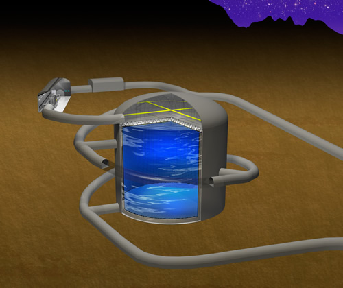 |
Hyper-Kamiokande is a next-generation, large-scale water Cherenkov neutrino detector. A dedicated task force determined the optimal tank design to be two cylindrical detectors that are 60 m in height and 74 m in diameter with 40% photocoverage, where a staging between the first and second tank is considered. We first focus on building the first tank in Japan, see Fig. 1 for the drawing.
Candidate sites for the Hyper-K experiment were selected such that neutrinos generated in the J-PARC accelerator facility in Tokai, Japan can be measured in the detector. J-PARC will operate a 750 kW beam in the near future, and has a long-term projection to operate with 1300 kW of beam power. Near detectors placed close to the J-PARC beam line will determine the information about the neutrinos coming from the beam, thus allowing for the extraction of oscillation parameters from the Hyper-K detector. The ND280 detector suite, which has been used successfully by the T2K experiment, could be upgraded to further improve the measurement of neutrino cross section and flux. The WAGASCI detector is a new concept under development that would have a larger angular acceptance and a larger mass ratio of water (and thus making the properties more similar to the Hyper-K detector) than the ND280 design. Intermediate detectors, placed 1-2 km from the J-PARC beam line, would measure the beam properties directly on a water target. Details of the beam, as well as the near and intermediate detectors, can be found in Section II.1.
Hyper-K is a truly international proto-collaboration with over 70 participating institutions from Armenia, Brazil, Canada, France, Italy, Korea, Poland, Russia, Spain, Sweden, Switzerland, Ukraine, the United Kingdom and the United States, in addition to Japan.
Hyper-K will be a multipurpose neutrino detector with a rich physics program that aims to address some of the most significant questions facing particle physicists today. Oscillation studies from accelerator, atmospheric and solar neutrinos will refine the neutrino mixing angles and mass squared difference parameters and will aim to make the first observation of asymmetries in neutrino and antineutrino oscillations arising from a CP-violating phase, shedding light on one of the most promising explanations for the matter-antimatter asymmetry in the Universe. The search for nucleon decays will probe one of the key tenets of Grand Unified Theories. In the case of a nearby supernova, Hyper-K will observe an unprecedented number of neutrino events, providing much needed experimental results to researchers seeking to understand the mechanism of the explosion. Finally, the detection of astrophysical neutrinos from sources such as dark matter annihilation, gamma ray burst jets, and pulsar winds could further our understanding of some of the most spectacular, and least understood, phenomena in the Universe. These topics will be discussed further in Section III.
This design report is organized as follows. There are a total of five parts. The remainder of this Part I.1 outlines the theoretical framework for the physics topics contained in this report and discusses the relationships between Hyper-K and other large-scale neutrino experiments. Part II describes the experimental configuration where Section II.1 describes the J-PARC neutrino beam line and near detector facility; Section II.2 discusses the technical details of the experimental design and Section II.3 details the software packages that will be utilized by the Hyper-K experiment. A discussion of pertinent radioactive backgrounds is contained in Section II.4. Part III explains the physics capabilities for Hyper-K. Part IV introduces a possible second tank in Korea. The last part, Part V, is the Appendix with details on the liner sheet tests (A) and a description of a possible second tank in Japan at Hakamagoshi (B).
I.1.1 Neutrino oscillations
Neutrino oscillations, discovered by the Super-Kamiokande (Super-K) experiment in 1998 Fukuda et al. (1998), implies that neutrinos have nonzero masses and flavor mixing, providing one of the most convincing experimental proofs known today for the existence of physics beyond the Standard Model (BSM). Indeed neutrino oscillation has been established as a very powerful tool to probe extremely small neutrino masses (or their differences) as well as lepton flavor mixing.
Throughout this design report, unless stated otherwise, we consider the standard three flavor neutrino framework. The 3 unitary matrix which describes the mixing of neutrinos Maki et al. (1962) (that is often referred to as the Pontecorvo-Maki-Nakagawa-Sakata (PMNS) or Maki-Nakagawa-Sakata (MNS) Pontecorvo (1968); Maki et al. (1962) matrix) relates the flavor and mass eigenstates of neutrinos as
| (1) |
where and denote neutrino fields with definite flavor and mass, respectively.
Using the standard parameterization, found, e.g. in Ref. Olive et al. (2014), can be expressed as,
| (14) |
where , , and — often called the Dirac phase —, is the Kobayashi-Maskawa type phase Kobayashi and Maskawa (1973) in the lepton sector. On the other hand, the two phases, and , — often called Majorana phases — exist only if neutrinos are of Majorana type Schechter and Valle (1980); Bilenky et al. (1980); Doi et al. (1981). While the Majorana phases can not be observed in neutrino oscillation, they can be probed by lepton number violating processes such as neutrinoless double beta () decay.
In the standard three neutrino flavor framework, only two mass squared differences, and , for example, are independent. Here, the definition of mass squared differences is . Therefore, for a given energy and baseline, there are six independent parameters that describe neutrino oscillations: three mixing angles, one phase, and two mass squared differences. Among these six parameters, and have been measured by solar Ahmad et al. (2002, 2001); Abe et al. (2011a) and reactor Eguchi et al. (2003); Araki et al. (2005); Abe et al. (2008) neutrino experiments. The parameters and (only its absolute value) have been measured by atmospheric Ashie et al. (2005, 2004) and accelerator Ahn et al. (2006); Adamson et al. (2011a); Abe et al. (2012a, 2014a) neutrino experiments. In the last few years, has also been measured by accelerator Abe et al. (2011b); Adamson et al. (2011b); Abe et al. (2013a, 2014b) and reactor experiments Abe et al. (2012b); Ahn et al. (2012); An et al. (2012, 2014); Abe et al. (2014c). Remarkably, the Super-K detector has successfully measured all of these mixing parameters, apart from the phase and the sign of . The current best-measured values of the mixing parameters are listed in Olive et al. (2014), where the mass hierarchy and phase are still unknown though there are some weak preferences by the current neutrino data as will be mentioned later in this section.
By studying neutrino oscillation behaviour, Hyper-K is expected to improve the current bounds obtained by Super-K for various non-standard neutrino properties, such as the possible presence of sterile neutrinos Abe et al. (2015a), non-standard interactions of neutrinos with matter Mitsuka et al. (2011), or violation of Lorentz invariance Abe et al. (2015b).
I.1.1.1 Mass Hierarchy
The positive or negative sign of (or equivalently that of ) corresponds, respectively, to the case of normal () or inverted () mass hierarchy (ordering). From a theoretical point of view, it is of great interest to know the mass hierarchy to understand or obtain clues about how the neutrino masses and mixing are generated (see e.g. Mohapatra and Smirnov (2006) for a review). Also the mass hierarchy has a significant impact on the observation of the decay for the case where neutrinos are Majorana particles. If the mass hierarchy is inverted, a positive signal of is expected in future experiments if the current sensitivity on the effective Majorana mass can be improved by about one order of magnitude beyond the current limit.
In the appearance channel, its oscillation probability at around the first oscillation maximum, , tends to be enhanced (suppressed) if the mass hierarchy is normal (inverted) due to the matter effect or the so called Mikheev-Smirnov-Wolfenstein (MSW) effect Mikheev and Smirnov (1985); Wolfenstein (1978) as we will see in Part III. For the antineutrino channel, , the effect become opposite, namely, the normal (inverted) mass hierarchy tends to suppress (enhance) the appearance probability. The longer the baseline (), larger the effect of such enhancement or suppression. Therefore, in principle, the mass hierarchy can be determined by measuring the oscillation probability provided that the matter effect is sufficiently large. This is the most familiar way to determine the mass hierarchy in neutrino oscillation which can be done using accelerator or atmospheric neutrinos.
Independently from this method, it is also possible to determine the mass hierarchy by observing the small interference effects caused by and in the medium baseline ( km) reactor neutrino oscillation experiment as first discussed in Petcov and Piai (2002). The proposed projects such as JUNO An et al. (2015) and RENO-50 Kim (2014) aim to determine the mass hierarchy by this method. Furthermore, in principle, it is possible to determine the mass hierarchy by comparing the absolute values of the effective mass squared differences determined by reactor ( disappearance) and accelerator ( disappearance) with high precision de Gouvea et al. (2005); Nunokawa et al. (2005).
It is expected by the time Hyper-K will start its operation, around the year 2025, the mass hierarchy could be determined at (3-4) or more by combining the future data coming from the ongoing experiments such as NOvA, T2K and reactor experiments, Daya Bay Guo et al. (2007), RENO Ahn et al. (2010), Double Chooz Ardellier et al. (2006), and proposed future experiments such as JUNO An et al. (2015), RENO-50 Kim (2014), ICAL Ahmed et al. (2015), PINGU Aartsen et al. (2014), and ORCA Katz (2014) where the last three projects will use atmospheric neutrinos to determine the mass hierarchy.
I.1.1.2 CP Violation
The magnitude of the charge-parity () violation in neutrino oscillation can be characterized by the difference of neutrino oscillation probabilities between neutrino and anti-neutrino channels Barger et al. (1980); Pakvasa (1980).
The current data coming from T2K Abe et al. (2015c) and NOvA Sanchez , when combined with the result of the reactor measurement, prefer the value around (or equivalently, ) for both mass hierarchies though the statistical significance is still small. Interestingly, the Super-K atmospheric neutrino data also prefers similar values with a similar statistical significance Wendell (2015).
If is maximally violated (), violation () could be established at (2-3) CL by combining the future data coming from T2K and NOvA as well as with data coming from the reactor measurements.
In Hyper-K the neutrino oscillation parameters will be measured using two neutrino sources which can provide complementary information. Both atmospheric neutrinos, where neutrino oscillations were first confirmed by Super-K, and a long baseline neutrino beam, where electron neutrino appearance was first observed by T2K, will be employed.
With a total exposure of 1.3 MW 108 sec integrated proton beam power (corresponding to protons on target with a 30 GeV proton beam) to a -degree off-axis neutrino beam, it is expected that the leptonic phase can be determined to better than 23 degrees for all possible values of , and violation can be established with a statistical significance of more than () for () of the parameter space.
Figure 2 shows how both CP-violation and mass hierarchy affect the difference between detection probability relative to detection probability for a given set of neutrino parameters.

I.1.2 Astrophysical neutrino observations
Hyper-K is also capable of observing neutrinos from various astrophysical objects. One main advantage of the detector is that its energy threshold can be set as low as several MeV; this enables us to reconstruct neutrinos from the Sun and supernovae on an event-by-event basis.
The Sun is an abundant and nearby source of neutrinos. Recently, Super-K showed the first indication of the terrestrial matter effects on 8B solar neutrino oscillations Renshaw et al. (2014). This was a direct confirmation of the MSW model Wolfenstein (1978); Mikheyev and Smirnov (1985, 1986) predictions for neutrino interactions with matter, which is also used to describe neutrino behaviour as it travels through the Sun. Furthermore, terrestrial matter effects hint at an intriguing possibility of using atmospheric and long baseline neutrinos to measure mass hierarchy and phase as both these parameters affect how neutrinos interact with matter. Hyper-K hopes to measure terrestrial matter effects with higher precision to better understand neutrino oscillation behaviour in the presence of matter. This also might resolve the tension between the current best fit values of from solar and reactor neutrino experiments, which is thought to be due to solar neutrino interactions in matter. Additionally, there are several physics goals for the solar neutrino observations in Hyper-K, such as long and short time variation of the 8B flux, the first measurement of neutrinos, and precise measurement of solar neutrino energy spectrum.
Computational simulations of core-collapse supernovae (CCSN) have failed to successfully reproduce explosions for more than 40 years. However, thanks to the recent advances in modeling techniques and the growth of available computation power, multi-dimensional (2D and 3D) simulations can now produce successful explosions Bruenn et al. (2013); Melson et al. (2015); Lentz et al. (2015); Takiwaki et al. (2014). Nevertheless, there are still some puzzles, such as the finding that the total explosion energy of the available multi-dimensional models is small compared to the SN1987A observation. Furthermore, the available 3D models are generally less energetic (or unsuccessful) compared with the more extensively simulated 2D models Couch and O’Connor (2014); Tamborra et al. (2013); Lentz et al. (2015); Takiwaki et al. (2014). Clearly, details of the supernova explosion mechanism are still lacking. High statistics observations of neutrinos from a CCSN (along with gravitational waves) are the only way to obtain precious inside information on the dynamics of the CCSN central engine and the explosion mechanism O’Connor and Ott (2013); Tamborra et al. (2013). If a CCSN explosion were to take place near the center of our Galaxy, Hyper-K would observe as many as tens of thousands of neutrino interactions (see Section III.3.1). Furthermore, Hyper-K will have the ability to precisely determine the arrival time of supernova neutrinos, which will help contribute to the understandings of both neutrino and CCSN properties. For example, by comparing of the number of and during the CCSN neutronization burst (first 10 msec) we will be able to determine the neutrino mass hierarchy (see Section III.3.1). High frequency timing will also provide experimental evidence of the multidimensional dynamics thought to be crucial in the CCSN explosion mechanism Tamborra et al. (2013). A large target volume like that of Hyper-K is also required to observe neutrinos from CCSN explosions in nearby ( few Mpc) galaxies. In this volume, CCSNe occur every few years Ando et al. (2005). Meanwhile, while waiting for a nearby explosion to occur, the continuous flux of relic supernova neutrinos from all past CCSN explosions in the observable universe will guarantee a steady accumulation of valuable astrophysical data.
Thanks to its good low energy performance for upward-going muons, Hyper-K has a larger effective area for upward-going muons below 30 GeV than do cubic kilometer-scale neutrino telescopes. Additionally, fully contained events in Hyper-K have energy, direction, and flavor reconstruction and resolutions as good as those in Super-K. This high performance will be useful for further background suppression or studies of source properties. For example, the detector is extremely sensitive to the energy range of neutrinos from annihilations of light (below 100 GeV) WIMP dark matter, a region which is suggested by recent direct dark matter search experiments. Hyper-K can search for dark matter WIMPs by looking for neutrinos created in pair annihilation from trapped dark matter in the Galactic centre or the centre of the Sun. Atmospheric neutrinos are a background to this WIMP search, so spacial cuts are made to determine if there is an excess of neutrinos coming from the Galactic centre or the Sun. Hyper-K will have the ability to detect both and components of the signal, making it more sensitive to this type of analysis.
The detection of neutrinos from solar flares is another astrophysics goal for Hyper-K. This will give us important information about the mechanism of the particle acceleration at work in solar flares. There have been some estimations of the number of expected neutrinos. Although it has large uncertainties, about 20 neutrinos will be observed at Hyper-K during a solar flare as large as the one in 20 January 2005. Hyper-K also has the potential to see neutrinos from astrophysical sources such as magnetars, pulsar wind nebulae, active galactic nuclei, and gamma ray bursts. The large target volume of Hyper-K, combined with the potential for these sources to emit neutrinos with energy at the GeV-TeV scale, could make Hyper-K an interesting experiment for observing these neutrinos. As with dark matter searches, the most significant background for detecting neutrinos for these astrophysical sources are atmospheric neutrinos. Spacial, and in some cases temporal, cuts need to be utilized to disentangle the astrophysical neutrino signal from the atmospheric neutrino background.
I.1.3 Nucleon decay searches
The stability of everyday matter motivated Weyl, Stueckelberg, Wigner, and other early quantum physicists to introduce a conserved quantity, baryon number, to explain the observed and unobserved particle reactions. Baryon number violation is believed to have played an important role during the formation of the universe, and comprises one of the famous Sakharov Conditions to explain the baryon asymmetry of the universe. Proton decay and the decay of bound neutrons are observable consequences of the violation of baryon number.
The Standard Model Lagrangian explicitly conserves baryon number, although anomalous quantum effects do violate baryon number at an unobservably tiny level. Nevertheless, there are reasons to believe that the Standard Model is part of a more expansive theory. Baryon number violation is a generic prediction of Grand Unified Theories (GUTs) that combine quarks and leptons and include interactions that allow their transition from one to the other. These theories are well motivated by observations such as the equality of the sum of quark and lepton charges, the convergence of the running gauge couplings at an energy scale of about GeV, and frequently have mechanisms to generate neutrino mass. If new forces carrying particles have masses at this GUT scale, the lifetime of the proton will be in excess of years, where past, present, and future proton decay experiments must search.
Baryon number violation has never been experimentally observed and lifetime limits, mainly by Super-Kamiokande, greatly restrict allowable Grand Unified theories and other interactions of interest to model building theorists. In Fig. 3, we show 90% CL lifetime limits by Super-Kamiokande and earlier experiments compared with representative lifetime ranges predicted by various GUTs. We also show the improvement in lifetime limits expected for 10 years of Hyper-Kamiokande exposure. The complementary experiment DUNE, assumed to be a 40 kt liquid argon time projection chamber (LArTPC) is also a sensitive to nucleon decay. Due to its smaller mass compared to Hyper-K, it is competitive mainly in modes with distinctive final state tracks such as those involving kaons.

The message the reader should conclude from this figure is that 10 years of Hyper-K exposure is sensitive to lifetimes that are commonly predicted by modern grand unified theories. The key decay channel has been emphasized, because it is dominant in a number of models, and represents a nearly model independent reaction mediated by the exchange of a new heavy gauge boson with a mass at the GUT scale. The other key channels involve kaons, wherein a final state containing second generation quarks are generic predictions of GUTs that include supersymmetry. Example Feynman diagrams are shown in Fig. 4.

Generally, nucleon decay may occur through multiple channels and ideally, experiments would reveal information about the underlying GUT by measuring branching ratios. It is a strength of Hyper-K that it is sensitive to a wide range of nucleon decay channels, however the few shown here are sufficient to discuss the details of the search for nucleon decay by Hyper-Kamiokande later in this document.
Practically, because of the stringent limits from more than 300 kty of Super-K running, the next generation experiments will have to concentrate on the discovery of nucleon decay, perhaps by one or a small number of events. The predictions are uncertain to two or three orders of magnitude, and one should not expect a negative search to definitively rule out the idea of GUTs. To excel in the search for proton decay, Hyper-Kamiokande requires the largest mass that is affordable in combination with sufficient instrumentation to minimize experimental background.
I.1.4 Synergies between Hyper-K and other neutrino experiments
This section will focus on understanding how Hyper-K will fit into the context of the global neutrino community. This includes currently operating experiments such as T2K and Super-K, as well as future experiments like DUNE.
I.1.4.1 T2K
T2K Abe et al. (2011b) is a currently-operating experiment which uses Super-K to measure neutrinos produced in the J-PARC beam line. Hyper-K will use much of the existing infrastructure used by T2K, particularly the beam line and near detectors. Hyper-K will also benefit from any improved data analysis techniques developed for T2K. Several important T2K upgrades and improvements are planned for the coming years, and this will have a direct impact on improved Hyper-K performance.
-
•
Near detector improvements: The T2K experiment uses the ND280 near detector suite. Future analysis improvements in the ND280 detector aim to reduce the cross section and flux uncertainties. Hardware upgrades, particularly to the time projection chamber component has also been proposed. The reader should refer to Section II.1.4.1 for the full details of the current and future status of the ND280 detector.
-
•
Increased beam power: J-PARC is planning an upgrade of the proton drivers in the neutrino beam. The near-term goal is to improve the beam power from 365 kW to 750 kW. After the proton driver upgrade, beam power is projected to reach 1300 kW. See Section II.1 for more details.
-
•
Better data analysis techniques: T2K demonstrated in its publications about appearance that aspects of the data analysis such rejection can be improved. Other improvements to the data analysis technique are under development, including detection efficiency, precision of the vertex determination (which could allow for an increased fiducial volume), and an improvement in separation.
In addition to benefiting directly from the upgraded hardware and analysis techniques, Hyper-K will also benefit from the expertise gained through implementing these upgrades. Furthermore, these upgrades can serve as a test bed for new near detector designs that have been proposed for Hyper-K (see Section II.1).
I.1.4.2 Super-K
In June 2015, the Super-Kamiokande Collaboration approved the SK-Gd project. This project is an upgrade of the detector’s capabilities, achieved by dissolving 0.2% gadolinium sulfate into Super-K’s water in order to enhance detection efficiency of neutrons from neutrino interactions. One of the main motivations of SK-Gd is to discover supernova relic neutrinos (SRN), the diffuse flux of neutrinos emitted by all supernovae since the beginning of the universe. SRN primarily interact in Super-K via inverse beta decay (IBD). Therefore, following the prompt detection of a positron, the accompanying IBD neutron can be identified in SK-Gd by a delayed gamma cascade, the result of the neutron’s capture on gadolinium. As a result of this positive identification of true IBD events, a much improved separation between signal and background can be achieved.
As Super-K will be the first example of gadolinium loading in a large-scale water Cherenkov detector, this will be a template for any future possibility of loading gadolinium into Hyper-K. In addition to determining the physics performance of gadolinium-loaded water, Hyper-K will also benefit from the extensive research done to optimize the water purification system, as well as the tests for material compatibility that was required to upgrade the Super-K detector.
I.1.4.3 DUNE
The Deep Underground Neutrino Experiment (DUNE), formerly LBNE LBN , is a 40 kilotonne liquid argon neutrino experiment that is projected to begin taking data around the same time as Hyper-K. Because DUNE will use a different target material than Hyper-K (liquid argon rather than water), many complementary measurements can be made, including nucleon decay measurements (as described in Section I.1.3) and supernova neutrino detection.
As mentioned in Section I.1.2, information about the neutrino signature from supernovae is much sought after, and Hyper-K and DUNE will each add to the overall picture. The primary reaction channel for these neutrinos in Hyper-K is the inverse beta decay channel, in which only electron antineutrinos will take part. In DUNE, the reaction channel will be the charged-current reaction on 40Ar, which measures electron neutrinos. Taken together, these measurements will be able to determine the relative abundance of neutrinos to antineutrinos. Furthermore, DUNE will be able to better determine some features of the neutrino spectrum which are dominated by the electron neutrino signal, such as the neutronization burst that occurs during early times, while Hyper-K will better measure features where there is an antineutrino signal, such as the accretion and cooling phases that occur at late times.
Due to the fact that the baseline between the accelerator facility and Hyper-K will be shorter than the proposed baseline for the DUNE experiment, the two experiments will have some complementarity in the information they can extract from their accelerator programs. The longer baseline to the DUNE experiment means their measurement will be more affected by matter effects, which will give them more sensitivity to the mass hierarchy. The shorter baseline of Hyper-K experiment means less sensitivity to matter effects, which should lead to an increased sensitivity to the measurement of the CP-violation phase. This is further described in Section III.1.1.
Part II Experimental Configuration
II.1 J-PARC neutrino beam facility
The accelerator neutrinos detected by Hyper-K are produced at the Japan Proton Accelerator Research Complex (J-PARC) JPA (2003). The proton accelerator chain, neutrino beamline and near detectors are located within J-PARC. Proposed intermediate detectors would be located near the J-PARC site at a distance of 1-2 km from the production target. This section describes the proton accelerator chain, neutrino beamline, near detectors and proposed intermediate detectors. In each case, the current configuration and future upgrades are described.
II.1.1 Neutrino beam and near detectors in long baseline oscillation measurements
The neutrino beam is produced by colliding 30 GeV protons extracted from the J-PARC accelerator chain with a 91 cm long graphite target. Three magnetic horns focus secondary charged particles that are produced in the proton-target collisions. The polarity of the horns’ currents determine which charge is focused and defocused, allowing for the creation of neutrino or antineutrino enhanced beams. The secondary particles are allowed to decay in a 96 m long decay volume. The dominant source of neutrinos is the decay of . Most are stopped in the absorber located at the end of the decay volume before they decay, and from decays contribute less than 1% to the total neutrino flux at at the peak energy.
The J-PARC beam is aimed 2.5∘ away from the Super-K and Hyper-K detectors to take advantage of the pion decay kinematics to produce a narrow band beam Beavis et al. (1995a) with a spectrum peaked at 600 MeV, at the first oscillation maximum for a baseline of 295 km. Fig. 5 shows the calculated energy dependent neutrino fluxes in the absence of neutrino oscillations impinging on Hyper-K for 320 kA horn currents in both horn polarities. Neglecting oscillations, neutrino detectors located near the neutrino source observe a similar neutrino spectrum to the far detector spectrum, but the peak of the spectrum is broader since the beam appears as a line source for near detectors, compared to a point source for far detectors.


The neutrino flux is calculated using a data-driven simulation that employs primary proton beam measurements, hadron production measurements, beamline element alignment measurements and horn current and field measurements Abe et al. (2013b). The dominant uncertainty on the flux calculation arises from modeling of hadron production in the graphite target and surrounding material. To minimize the hadron production uncertainties, the NA61/SHINE experiment Abgrall et al. (2014) has measured particle production with 30 GeV protons incident on a thin (4% of an interaction length) target Abgrall et al. (2011a, 2012), and a replica T2K target Abgrall et al. (2013). The thin target data have been used in the T2K flux calculation, and a 10% uncertainty on the flux calculation has been achieved, as shown in Fig. 6. Much of the remaining uncertainty arises from the modeling of secondary particle re-interactions inside the target. Preliminary work suggests that the hadron production uncertainty can be reduced to by using the NA61/SHINE measurement of the particle multiplicities exiting the T2K replica target Haesler (2015). In the context of Hyper-K, the thin target data from NA61/SHINE are applicable to the flux calculation, and the replica target data may also be used if the target geometry does not change significantly. If the target geometry or material are changed for Hyper-K, then new hadron production measurements will be necessary.


The near neutrino detectors of T2K are located 280 m from the pion production target and they include the INGRID on-axis detector Otani et al. (2010) and the ND280 off-axis detector Assylbekov et al. (2012); Allan et al. (2013); Aoki et al. (2013); Amaudruz et al. (2012); Abgrall et al. (2011b). The INGRID detector is used primarily to measure the beam direction and neutrino yield, while ND280 measurements provide constraints on the neutrino flux and interaction models that are used to predicted the event rate at the far detector after oscillations. Measurements with the ND280 detector are used for both dedicated neutrino cross-section measurements and event rate constraints that are used directly in neutrino oscillation measurements. For neutrino cross-section measurements, the neutrino flux is derived from the previously described flux calculation and the neutrino cross-section is inferred from the event rate and particle kinematics measured with the ND280 detector. The cross-section measurements provide constraints on the building of models of neutrino-nucleus interactions that are ultimately used in oscillation measurements. For the oscillation measurements themselves, nuisance parameters are introduced to describe the uncertainty on the neutrino flux and interaction models. A fit to a subset of the ND280 data simultaneously constrains the flux and interaction model nuisance parameters, and the predicted event rate and uncertainty at the far detector are updated Abe et al. (2015c). The beam direction measurement, neutrino cross section measurements and direct constraints on the neutrino event rate for oscillation measurements are all necessary for long baseline oscillations measurements at Hyper-K.
II.1.2 The J-PARC accelerator chain
The J-PARC accelerator cascade JPA (2003) consists of a normal-conducting LINAC as an injection system, a Rapid Cycling Synchrotron (RCS), and a Main Ring synchrotron (MR). H- ion beams, with a peak current of 50 mA and pulse width of 500 s, are accelerated to 400 MeV by the LINAC. Conversion into a proton beam is achieved by charge-stripping foils at injection into the RCS ring, which accumulates and accelerates two proton beam bunches up to 3 GeV at a repetition rate of 25 Hz. Most of the bunches are extracted to the Materials and Life science Facility (MLF) to generate intense neutron/muon beams. The beam power of RCS extraction is rated at 1 MW. With a prescribed repetition cycle, four successive beam pulses are injected from the RCS into the MR at 40 ms (= 25 Hz) intervals to form eight bunches in a cycle, and accelerated up to 30 GeV. In fast extraction (FX) mode operation, the circulating proton beam bunches are extracted within a single turn into the neutrino primary beamline by a kicker/septum magnet system.
| Parameter | Achieved | Original | Doubled rep-rate | Long-term Projection |
|---|---|---|---|---|
| Circumference | 1,567.5 m | |||
| Beam kinetic energy | 30 GeV | 50 GeV | 30 GeV | 30 GeV |
| Beam intensity | ppp | ppp | ppp | ppp |
| ppb | ppb | ppb | ppb | |
| RCS equivalent power | 575 kW | 1 MW | 610 kW | 1 MW |
| Harmonic number | 9 | |||
| Bunch number | 8 / spill | |||
| Spill width | 5 s | |||
| Bunch full width at extraction | 50 ns | – | 50 ns | 50 ns |
| Maximum RF voltage | 280 kV | 280 kV | 560 kV | 560 kV |
| Repetition period | 2.48 sec | 3.52 sec | 1.32 sec | 1.16 sec |
| Beam power | 485 kW111As of 2018 | 750 kW | 750 kW | 1340 kW |
In the MR FX mode operation, a beam intensity of 2.451014 proton-per-pulse (ppp) has been achieved, corresponding to 485 kW beam power (as of 2018). The accelerator team is following a concrete upgrade scenario Koseki (2014) to reach the design power of 750 kW in forthcoming years, with a typical planned parameter set as listed in Table 2. This will double the current repetition rate by (i) replacing the magnet power supplies, (ii) replacing the RF system, and (iii) upgrading injection/extraction devices. Based on high intensity studies of the current accelerator performance, it is expected that 1-1.3 MW beam power can be achieved after these upgrades Koseki (2015); Kobayashi (2015). The projected beam performance up to 2028 is shown in Fig. 7. For operation larger than 2 MW beam power, conceptual design studies are now underway Igarashi et al. , and they include approaches such as raising the RCS top energy, enlarging the MR aperture, or inserting an “emittance-damping” ring between the RCS and MR.

II.1.3 Neutrino beamline

Fig. 8 shows an overview of the neutrino experimental facility Abe et al. (2011c). The primary beamline guides the extracted proton beam to a production target/pion-focusing horn system in a target station (TS). The pions decay into muons and neutrinos during their flight in a 96 m-long decay volume. A graphite beam dump is installed at the end of the decay volume, and muon monitors downstream of the beam dump monitor the muon profile. The beam is aimed 2.5∘ off-axis Beavis et al. (1995b) from the direction to Super-K and the beamline has the capability to vary the off-axis angle between 2.0∘ to 2.5∘. The centreline of the beamline extends 295 km to the west, passing midway between Tochibora and Mozumi, so that both sites have identical off-axis angles.

II.1.3.1 Secondary beamline
The secondary beamline consists of the beamline from the TS entrance to the muon monitors. Fig. 9 shows a cross section of the secondary beamline, and a close-up of the TS helium vessel. The secondary beamline components and their capability to accept high power beam are reviewed here.
A helium cooled, double skin titanium alloy beam window separates the helium environment in the TS vessel (1 atm pressure) from the vacuum of the primary beamline. The proton beam collides with a helium-cooled graphite production target that is inserted within the bore of the first of a three-horn pion-focusing system. At 750 kW operation, a 20 kW heat load is generated in the target. The neutrino production target and the beam window are designed for 750 kW operation with 3.31014 ppp (equivalent to RCS 1 MW operation) and 2.1 sec cycle. In the target, the pulsed beam generates an instantaneous temperature rise per pulse of 200 C∘ and a thermal stress wave of magnitude 7 MPa. Given the tensile strength, the safety factor is 5. Although the tensile strength and safety factor will be reduced by cyclic fatigue, radiation damage and oxidization of the graphite, a lifetime of 25 years is expected.
The horns are suspended from the lid of the TS helium vessel. Each horn comprises two co-axial cylindrical conductors which carry up to a 320 kA pulsed current. This generates a peak toroidal magnetic field of 2.1 Tesla which focuses one sign of pions. The heat load generated in the inner conductors by secondary particles and by joule heating is removed by water spray cooling. So far the horns were operated with a 250 kA pulsed current and a minimum repetition cycle of 2.48 sec. To operate the horns at a doubled repetition rate of 1 Hz requires new individual power supplies for each horn utilizing an energy recovery scheme and low inductance/resistance striplines. These upgrades will reduce the charging voltage/risk of failure, and, as another benefit, increase the pulsed current to 320 kA. The horn-1 water-spray cooling system has sufficient capacity to keep the conductor below the required 80∘C at up to 2 MW.
All secondary beamline components become highly radioactive during operation and replacements require handling by a remotely controlled overhead crane in the target station. Failed targets can be replaced within horn-1 using a bespoke target installation and exchange mechanism.
Both the decay volume and the beam dump dissipate 1/3 of the total beam power, respectively. The steel walls of the decay volume and the graphite blocks of the hadron absorber (core of the beam dump) are water cooled and both are designed to accept 34 MW beam power since neither can be upgraded nor maintained after irradiation by the beam.
Considerable experience has been gained on the path to achieving 475 kW beam power operation, and the beamline group is promoting upgrades to realize 750 kW operation and to expand the facilities for the treatment of activated water. Table 3 gives a summary of acceptable beam power and/or achievable parameters for each beamline component Yamada (2014); Tada (2014), for both the current configuration and after the proposed upgrades in forthcoming years.
| Component | Acceptable beam power or achievable parameter | |
|---|---|---|
| Target | 3.31014 ppp | |
| Beam window | 3.31014 ppp | |
| Horn | ||
| cooling for conductors | 2 MW | |
| stripline cooling | ( 750 kW ) | 3 MW |
| hydrogen production | ( 1 MW ) | 2 MW |
| power supply | ( 250 kA ) | 320 kA |
| ( 0.4 Hz ) | 1 Hz | |
| Decay volume | 4 MW | |
| Hadron absorber (beam dump) | 3 MW | |
| water-cooling facilities | ( 750 kW ) | 2 MW |
| Radiation shielding | ( 750 kW ) | 4 MW |
| Radioactive cooling water treatment | ( 600 kW ) | 1.3 MW |
II.1.4 Near detector complex
The accelerator neutrino event rate observed at Hyper-K depends on the oscillation probability, neutrino flux, neutrino interaction cross-section, detection efficiency, and the detector fiducial mass of Hyper-K. To extract estimates of the oscillation parameters from data, one must model the neutrino flux, cross-section and detection efficiency with sufficient precision. In the case of the neutrino cross-section, the model must describe the exclusive differential cross-section that includes the dependence on the incident neutrino energy, , the kinematics of the outgoing lepton, momentum and scattering angle , and the kinematics of final state hadrons and photons. In our case, the neutrino energy is inferred from the lepton kinematics, while the reconstruction efficiencies depend on the hadronic final state as well.
The near detectors measure the neutrino interaction rates close enough to the neutrino production point so that oscillation effects are negligible. The prediction of event rates at Hyper-K for a given set of oscillation parmeters will be precisely constrained by event rates measured in the near detector and the flux simulation based on hadron production data from NA61/SHINE and other hadron production experiments. Our approach to using near detector data will build on the experience of T2K while considering new near detectors that address limitations in reducing neutrino cross section modelling uncertainties with the current T2K near detector suite.
The near detectors should be capable of measuring the signal and background processes relevant for neutrino oscillation measurements made using the accelerator produced neutrinos. The processes include:
-
•
The charged current interactions with no detected final state pion (CC0) that are the signal channel for the oscillation measurements in Hyper-K.
-
•
The intrinsic electron neutrino component of the beam from muon and kaon decays, which is a background for the electron (anti)neutrino appearance signal.
-
•
The neutral current interactions with production (NC) that are a background for the electron (anti)neutrino appearance signal.
-
•
The wrong-sign charged current processes (neutrinos in the antineutrino beam and vise versa) which are a background in the CP violation measurement.
In addition to measuring these processes, the near detectors should be designed to maximize the cancellation of systematic uncertainties when extrapolating from measured event rates in the near detector to predict the event rate at Hyper-K. Hence, the near detector should be able to make measurements with the same angular acceptance (4) and target nuclei (H2O) as Hyper-K. Another source of uncertainty in the extrapolation is the difference between the near and far detector neutrino spectra due to oscillations, which can amplify systematic errors related to the modeling of the relationship between the final state lepton kinematics and the incident neutrino energy Martini et al. (2012); Lalakulich et al. (2012); Martini et al. (2013). The near detectors should be able to sufficiently constrain the modeling of the dependence of lepton kinematics on neutrino energy over the relevant neutrino energy range.
The near detectors can also be used to constrain important neutrino interaction modes for atmospheric neutrino and nucleon decay measurements at Hyper-K. For example, Hyper-K may use neutron captures on Gd or H to statistically separate neutrinos and antineutrinos in the atmospheric measurements, or to reject atmospheric neutrino backgrounds in the nucleon decay measurements. The neutron multiplicities produced in the interactions of neutrinos and antineutrinos with energy of 1 GeV can be measured in the near detectors. The dominant sources of uncertainty in the determination of the mass hierarchy and quadrant with atmospheric neutrinos are uncertainties in the neutrino to anti-neutrino cross section ratio for both CCQE and single pion production modes, the axial vector nucleon form factor, the neutrino-tau cross section, and the DIS cross section model. Near detector measurements that would constrain these uncertainties for interactions on water, have the potential to significantly improve the sensitivity of these atmospheric neutrino measurements. The near detectors can also be used to measure the interaction modes for nucleon decay backgrounds, including the CC background to the mode and the kaon production background to the mode.
To summarize, the near and intermediate detectors for Hyper-K should cover the full momentum and angular acceptance of the far detector, include homogenous H2O targets to make precision measurements on H2O, have sign selection capability to measure wrong sign backgrounds, be capable of directly measuring intrinsic and NC backgrounds, be capable of reconstructing exclusive final states with low particle thresholds, be capable of measuring the cross sections, be capable of measuring the final state neutron multiplicities and be capable of measurements at multiple off-axis angles with varying peak neutrino energies. We have not identified a single detector technology that can achieve all of these capabilities. In the minimum configuration, it is necessary to have both a magnetized tracking detector and kiloton scale water Cherenkov detector. The magnetized tracking detector may provide full momentum and angular acceptance, sign selection, reconstruction of exclusive final states with low particle thresholds, measurement of the rates and off-axis spanning measurements. The water Cherenkov detector may provide full angular acceptance, a homogenous water target, direct measurement of the intrinsic and NC backgrounds, measurement of the cross sections, measurements of final state neutron multiplicities and the off-axis spanning measurements. Hence, in the following text we present the upgrade for the current ND280 magnetized tracking detector, new tracking detector technologies, and intermediate water Cherenkov detectors as potential components of the Hyper-K near and intermediate detector suite.
II.1.4.1 The ND280 Detector Suite
The T2K ND280 detector suite, shown in Fig. 10, comprises two detectors: INGRID Otani et al. (2010), which consists of 16 iron-scintillator modules in a cross pattern centered on the neutrino beam axis, and ND280, a multi-component detector at an angle of 2.5∘ from the beam direction. The primary purpose of the INGRID detector is to constrain the neutrino beam direction, whilst the off-axis detector is used to characterise the various neutrino interaction rates before oscillations.

The ND280 off-axis detector is composed of an inner tracking region surrounded by an upstream Pi-zero detector Assylbekov et al. (2012), electromagnetic calorimeters Allan et al. (2013) and side muon range detectors Aoki et al. (2013), all of which are held inside the UA1 magnet. The 0.2 T magnetic field allows for momentum measurement and sign selection of charged particles, and is important for operation in antineutrino mode where the neutrino background is large. The tracking region is composed of three time projection chambers (TPCs) Abgrall et al. (2011b) separated by two fine grained detectors (FGDs) Amaudruz et al. (2012), the second of which contains passive water layers to allow for neutrino interaction rate measurements on oxygen. The FGDs are the neutrino target whilst the TPCs provide precise momentum measurements, particle identification and sign selection.
T2K has successfully applied a method of fitting to ND280 data with parameterized models of the neutrino flux and interaction cross-sections, as described in Abe et al. (2015c). Using the ND280 measurements, the systematic uncertainties (estimated assuming specific models) on neutrino interaction processes constrained by ND280 have been reduced to 3% on the Super-K (SK) predicted event rates, as shown in Table 4.
| Source of uncertainty | ||||
| Flux and common cross sections | ||||
| (w/o ND280 constraint) | 10.8% | 10.9% | 11.9% | 12.4% |
| (w/ ND280 constraint) | 2.8% | 2.9% | 3.3% | 3.2% |
| Unconstrained cross sections | 0.8% | 3.0% | 0.8% | 3.3% |
| SK | 3.9% | 2.4% | 3.3% | 3.1% |
| FSI + SI(+ PN) | 1.5% | 2.5% | 2.1% | 2.5% |
| Total | ||||
| (w/o ND280 constraint) | 11.9% | 12.2% | 13.0% | 13.4% |
| (w/ ND280 constraint) | 5.1% | 5.4% | 5.2% | 6.2% |
Current limitations and future analysis improvements
As shown in Table 4, the uncertainty in the estimated neutrino flux numbers at Super-K are 5–6%. Without the near detector constraints, the uncertainties would be more than double this, but with the flux and cross-section uncertainties contributing roughly half the total uncertainty, tighter near detector constraints are still necessary to achieve the 1–2% systematic target for Hyper-K physics measurements.
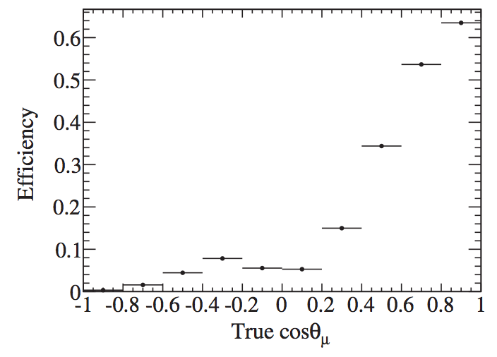
Cross section model parameters unconstrained by the near detector (“Unconstrained cross sections” in Table 4) are more significant for the and rates due to the uncertainty on the and cross sections relative to and . Reduction of these uncertainties with direct measurements is a challenge due to the relative small fraction of intrinsic and in the beam before oscillations. Separate selections with interactions in FGD1 (all scintillator) and FGD2 (40% water, 60% scintillator by mass) help to constrain cross-sections on water. Compared to a measurement on a pure water target, additional systematic and statistical errors are introduced on the FGD2 water measurements due to the uncertainties on the subtraction of interactions on the scintillator in FGD2. Another limitation of the current ND280 analysis is the difference in acceptance between ND280 and SK. These differences in accessible phase space mean that ND280 and SK are sensitive to different parts of the neutrino interaction model, which introduces additional uncertainty when performing oscillation analyses. The current ND280 analysis of CC events with no pions has an efficiency that strongly depends on the angle of the muon trajectory relative to the Z axis, which is roughly aligned with the neutrino beam direction. Fig. 11 shows the angular dependence of the efficiency for events in FGD1, which is 50% when the cosine of the angle is 0.6 Abe et al. (2016a). Future analysis improvements will provide some acceptance of events at greater angles and with backward-going muons, but will not provide the same coverage as a true detector, such as SK. Other potential analysis improvements include the use of pion kinematic information in addition to the muon kinematic information of the ND280 selected events which could help reduce potential reconstruction bias in the neutrino energy.
A fundamental limitation of near detectors in oscillation analyses is that the near and far detectors do not sample the same neutrino spectrum due to the neutrino oscillations. Since the observed final state particle distributions are produced by different spectra in the near and far detectors, the interaction models are necessary to extrapolate the rate observed with the near detector spectrum to the rate expected with the far detector spectrum. This extrapolation is sensitive to the modeling of the observed final state particle kinematics for each incident neutrino energy. For water Cherenkov detectors such as Hyper-K, the relation of the final state lepton kinematics and neutrino energy for events with only a visible lepton is critical since the neutrino spectrum is infered from the lepton kinematics, and the signal sample is chosen by the presence of a single lepton candidate ring. If this relationship is not properly modeled, systematic biases will arise in the extrapolation. This effect has been studied for both muon neutrino disappearance and electron neutrino appearance measurements and found to be a potentially limiting source of systematic uncertainty for the oscillation measurements Martini et al. (2012, 2013); Lalakulich et al. (2012); Coloma et al. (2014). Measurements of neutrino interactions from multiple neutrino spectra peaked at different energies may be used to constrain and improve the models to the level necessary for Hyper-K. This may be done at different experiments or with a single experiment by using the off-axis dependence of the neutrino beam. Alternatively, measurements at many off-axis angles may also be used to directly predict the expected event rate for the oscillated spectrum, as discussed in Section II.1.4.3. The models may also be improved with better measurements of exclusive final hadronic states.
In summary, we expect some decrease in the uncertainty (current value 3–4%) in the event rate prediction from the flux and cross section model from future analysis improvements at ND280 but upgrades to the ND280 hardware, as discussed in the next section could significantly increase sensitivity to interactions on water and those with leptons at large angles thus providing new samples to further drive down the uncertainties. However, there are fundamental limitations to the ND280 upgrade potential, due to size and space constraints within the magnet, so we also need to consider alternative water cerenkov detection as discussed in the following sections.
ND280 Hardware Upgrade possibilities
The upgrade of the ND280 detector has become an official T2K project since February 2017. Its goal is to reduce the total systematic uncertainties on the neutrino event rate prediction at the far detector, in the presence of oscillations, to better than 4% by improving the acceptance of particles produced at high angles or backward-going. The basic idea is to cover almost all the angular region thanks to a neutrino target detector rotated along the neutrino beam direction sandwiched between two horizontal TPCs.
The proposed ND280 upgrade is shown in Fig. 12. The upgrade keeps the current ND280 tracker, i.e. three vertical TPCs and two FGDs, and would replace the P0D detector with a longer horizontal target sandwiched between two horizontal TPCs. The upgraded detector also keeps the current Electromagnetic Calorimeter (ECal). Furthermore, in order to veto the sand muons and ’s produced in the magnet or cosmic particles, both coming from the upstream part of the detector, the Upstream ECal of the P0D detector (ECal-P0D) would be kept, providing . In addition the Central ECal-P0D could also be used, providing in total a radiator of .
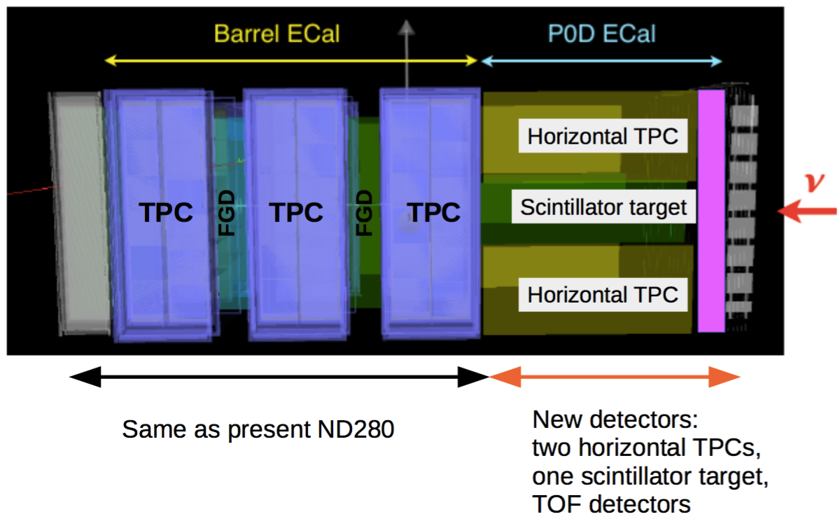
In addition to the new tracker, a Time-of-Flight (ToF) detector would be built, with the goal to improve the reconstruction of backward-going tracks, poorly detected by the current ND280 detector. Studies are ongoing in order to understand the impact of the ToF on the particle identification, combined with the TPCs. The ToF detector would be placed all around the new horizontal tracker. Furthermore two vertical ToFs may be placed one between the Upstream ECal-P0D and the tracker and the other one between the Downstream ECal and the tracker.
Currently different neutrino target detectors are considered for the new horizontal tracker: a WAGASCI detector, empty or filled with water (described in the next paragraph and shown in Fig. 14–14), an FGD-like detector rotated along the neutrino beam direction, an FGD-3D, same as FGD but with additional plastic scintillator bars along the third axis, a tracking fiber detector and a SuperFGD, made of many plastic scintillator cubes, in order to detect tracks with a 4 acceptance.
WAGASCI (Water Grid And SCIntillator detector), is a new neutrino detector with a water target under development to measure neutrino interactions with high precision and a large angular acceptance. The concept uses a 3D grid-like structure of scintillator bars to track charged particles across the full solid angle (Fig. 14 and 14), which provides a larger angular acceptance and larger mass ratio of water to scintillator bars (80:20) than the current off-axis ND280 detector.


Such a detector could be installed within the ND280 magnet as part of the upgrade, but as a first step, WAGASCI modules with water and hydrocarbon targets will be installed on the B2 and SS floors of the near detector hall at J-PARC surrounded by massive muon range detectors to range out the muons Asfandiyarov et al. (2014). These detectors have been approved by the J-PARC PAC as test experiment T59 and will measure neutrino cross sections on water and hydrocarbon Bonnemaison et al. (2014). By comparing the observed interaction rate in the two targets, the inclusive water to hydrocarbon charged current cross section ratio can be measured with better than 3% precision, an established technique that has been shown to work by the current INGRID detector Abe et al. (2014d).
In Tab. 5 the momentum threshold for different particles corresponding to a WAGASCI-like detector with size is shown. If WAGASCI is empty the momentum threshold for protons is about 300 MeV/c.
| Detector | thresholds | pp threshold | |
|---|---|---|---|
| Water-In | 150 MeV/c | 150 MeV/c | 550 MeV/c |
| Water-Out | 50 MeV/c | 50 MeV/c | 300 MeV/c |
Tab. 6 shows the neutrino target mass for the current ND280 and proposed upgrade and the number of neutrino events obtained after applying the full event selection for an exposure of POT. A simplified MC study, without a full event reconstruction, has been used. The ND280 upgrade increases the total target mass, giving twice the event rate for the same exposure.
| Number of Selected Events | ||||
|---|---|---|---|---|
| Detector Configuration | Target Mass (ton) | CC- ( beam) | CC- ( beam) | CC- ( beam) |
| Current ND280 | 2.2 | 95,860 | 27,443 | 14,862 |
| ND280 Updgrade | 4.3 | 199,775 | 54,249 | 28,370 |
One possibility is to replace the existing tracker region with a high pressure TPC, as was proposed for the LBNO design study Stahl et al. (2012). This would allow full angular coverage and a very detailed view of the vertex as well as superb particle identification and sensitivity to low momentum protons. A strength of a gas TPC in the case of T2K and Hyper-K is that it will be possible to change the target gas, which allows testing the nuclear model components of the neutrino-nucleus interaction simulation. Gas TPCs have been operated successfully with a wide range of gases, including He, CH2, Ne, Ar, CF4, and an N2:CO2 mixture that is 60% oxygen by mass. This would provide data samples unavailable to other experiments (or near detector designs), and that complementarity will help break degeneracies that arise from modelling neutrino-nucleus interactions. The ND280 tracker region could easily accommodate a TPC with 8 m3 fiducial volume, which at 10 bar pressure would accumulate sizeable data sets of CC-inclusive interactions as shown in Table 41. A gas TPC should also provide a relatively pure sample, because of the significantly reduced gamma backgrounds compared to the existing ND280, allowing data sets of hundreds of events per POT on the heavier gas targets, as shown in Table 41.
Another option to probe the hadronic final state and enhance our understanding of neutrino-nucleus interactions and to measure the low energy interaction cross-section is to add an emulsion detector to the ND280 suite. Emulsions provide 3D tracking with sensitivity to protons down to 20 MeV, and sub micrometer position accuracy through offline scanning Fukuda et al. (2014).
II.1.4.2 Intermediate detector
A water Cherenkov (WC) near detector can be used to measure the cross section on H2O directly, with the same solid angle acceptance as the far detector with no need for a subtraction analysis. This approach was taken by K2K Ahn et al. (2006) and was proposed for T2K Kearns et al. (2005). The MiniBooNE experiment has also employed a mineral oil Cherenkov detector at a short baseline to great success Aguilar-Arevalo et al. (2009). Additionally, WC detectors have shown excellent particle identification capabilities, allowing for the detection of pure -CC, -CC and NC samples. The CC rate and kaon production in neutrino interactions, which are backgrounds to nucleon decay searches, can also be measured.
These additional WC measurements are essential to achieve the low systematic errors required by Hyper-K, but are complemented by the ND280 magnetised tracking detector, which has the capabilities to track particles below the threshold to produce Cherekov light in water and to separate neutrino and antineutrino charged current interactions via the lepton charge measurement. Hence a combination of a magnetized tracking detector such as ND280 and the WC detector should have the largest impact to reduce systematic uncertainties.
A WC near detector design should be large enough to contain muons up to the momentum of interest for measurements at the far detector and should be far enough from the neutrino production point that there is minimal pile-up of interactions in the same beam timing bunch. These requirements lead to designs for kiloton size detectors located at intermediate distances, 0.7-2 km from the target, for the J-PARC neutrino beam.
Here we present the two main features that are being considered for the WC detector:
-
•
A detector that spans an off-axis angle range of to measure the final state leptonic response over a range of neutrino spectra peaked at different energies. Measurements at multiple off-axis angles can be used to address the limitation of different neutrino spectra at the near and far detectors.
-
•
Gd loading in the WC detector allows for the measurement of neutron multiplicities in neutrino and antineutrino interactions. These measurements can be used for statistical separation of neutrino and antineutrino interactions as well as different interaction modes and may be applied to the atmospheric and accelerator neutrino analyses in Hyper-K. The measurements can also be used to predict the rejection of nucleon decay backgrounds in Hyper-K with neutron tagging.
An international collaboration called E61 was formed in May 2017, combining groups working on the off-axis spanning detector and Gd loading features. The E61 collaboration is working closely with the Hyper-K near detector working group to develop a detector design that meets the goals of Hyper-K. The E61 collaboration has proposed a staged approach to realize the final intermediate water Cherenkov detector (IWCD). The initial phase would consist of a kiloton scale detector on the surface near the current ND280 detectors at an off-axis angle of 6–12∘. The initial phase may provide a test-bed for new detector technolgies to be used in the IWCD and Hyper-K, and will be used to prove that the kiloton scale water Cherenkov detector can be calibrated with sufficient precision to make neutrino interaction measurements with percent level systematic errors. The E61 collaboration proposes the second phase of the intermediate water Cherenkov detector as an intermediate detector for Hyper-K.
The IWCD will also have its own physics program independent from the measurements in service to Hyper-K. At a 0.7-2 km baseline, it can search for neutrino oscillations through sterile neutrinos, on its own and in combination with ND280. The WC detector can also be used as an independent supernova alarm, and with the addition of gadolinium, would provide valued neutrino-type discrimination in the event of a supernova in the local galaxy.
In the following text, the above main features of the intermediate detector will be described in more detail, making use of the studies from other detectors.
II.1.4.3 Off-axis angle spanning configuration
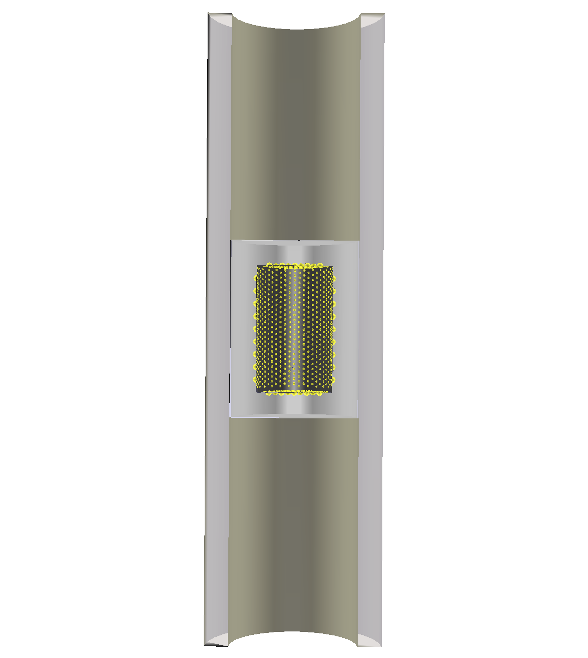
The intermediate WC detector can be oriented with the polar axis of the cylinder in the vertical direction and the detector extending from the ground level downward. This configuration was originally proposed as the NuPRISM detector Bhadra et al. (2014), located at a baseline of 1 km filling a 10 m diameter, 50 m deep pit. Fig. 15 shows the conceptual drawing for the NuPRISM detector and the spectra for the off-axis angle range spanned by the detector. The baseline design for the detector is an instrumented structure with a 10 m tall inner-detector containing 3215 8 inch inward facing photomultiplier tubes to detect the Cherenkov light, giving 40% photo-coverage. A crane system will move the detector structure vertically in the 50 m pit to make measurements at different off-axis angles. By orienting the long axis of the detector perpendicular to the beam direction, the detector covers a range of angles relative to the beam direction. Hence, each vertical slice of the detector samples a different neutrino spectrum due to the decay kinematics of the pions and kaons producing the neutrinos, the so-called off-axis beam effect.

There are three primary motivations for making neutrino measurements over a range of off-axis angles. First, the change in the neutrino spectrum with off-axis angle is well known from the flux model, so the predicted off-axis spectra can be combined in a linear combination to produce almost arbitrary neutrino spectra. Measured distributions at different off-axis angles can be combined in the linear combination to produce the predicted measured quantity for the neutrino spectrum of interest. In this way, it is possible to measure the muon spectrum for a nearly mono-chromatic neutrino spectrum, or a spectrum that closely matches the oscillated spectrum that is expected at the far detector. This approach can nearly eliminate the main model dependent uncertainty in near to far extrapolations, which arises from the combination of two factors: the near and far detector do not see the same flux due to oscillations, and the relationship between the true neutrino energy and final state lepton kinematics strongly depends on nuclear effects, which are not well modelled Bhadra et al. (2014).
The second physics motivation is the measurement of the electron neutrino cross section relative to the muon neutrino cross section. At further off-axis positions, the fraction of intrinsic in the beam becomes large, making the selection of pure candidate samples possible. By taking advantage of the enhanced purity at large off-axis angles, a measurement of the cross section ratio, with 3% precision or better may be possible. A measurement of the ratio is also possible, although the precision is expected to be degraded due to the larger neutral current background rate for electron antineutrino candidates and the presence of a larger wrong-sign background for both muon and electron antineutrino charge current interactions.
The third physics motivation is the search for sterile neutrino induced oscillations that are consistent with the LSND Aguilar-Arevalo et al. (2001) and MiniBooNE Aguilar-Arevalo et al. (2013) and appearance anomalies. At a 1 km baseline, the of the neutrino spectrum peak varies between 1.1 km/GeV at off-axis to 2.5 km/GeV at off-axis. Since the neutrino spectrum varies with off-axis angle, it is possible to search for the oscillation pattern not only through the reconstructed energy of the neutrino candidate events, but also through the reconstructed off-axis angle. This method provides a significant improvement in the electron neutrino appearance search sensitivity, and preliminary studies with a non-optimal detector configuration already show that much of the LSND allowed region can be excluded at 5 Bhadra et al. (2015).
II.1.4.4 Gadolinium Loading
Recent developments in the addition of gadolinium (Gd) Watanabe et al. (2009) and Water-based Liquid Scintillator (WbLS) compounds Alonso et al. (2014) to water raise the possibility to separate neutrino and antineutrino interactions by detecting the presence of neutrons or protons in the final state.
Final state proton tagging has been studied intensively for an application for LArTPC detectors Acciarri et al. (2014), where final state protons can be counted to further purify the sample to improve the oscillation sensitivity Mosel et al. (2014). An analogous approach is possible for the larger WC detectors. Namely, Gd-doped WC detectors possess neutron tagging ability on top of the 4 detector coverage Abe et al. (2014e), which allows statistical separation of primary interaction modes, otherwise impossible. In particular, the ability to tag neutrons provides charge separation information due to the enhanced presence of neutrons in the final state for charged current interactions. This will allow studies of neutrino:anti-neutrino cross-section ratios on water and constraints on wrong-sign backgrounds, thus reducing a critical systematic uncertainty in both the beam and atmospheric neutrino oscillation analyses. Neutron tagging also allows more detailed studies of the interaction modes, and in particular final state interaction effects, for the main backgrounds to proton decay.
The TITUS detector was originally proposed to provide an intermediate detector with neutron tagging capabilities for Hyper-K as described in Ref. TIT . Figure 16 shows an example of a WC near detector simulation study for TITUS in which selecting “neutron1” increases the selection purity for CCQE interactions and hence improves the energy resolution. This technique will be also applied to the ANNIE experiment Anghel et al. (2015) in the next years.


One aspect of the intermediate detector’s design that needs to be carefully considered with Gd-doped water is how to veto incoming neutrons from beam-induced interactions in the material surrounding the detector which will be the dominant contributor for the number of particles entering the detector. Vetoing most of these particles requires at least 1 m of water to reduce the low energy tail, plus a fiducial cut on the reconstructed capture vertex. Preliminary studies using spallation rates induced by muons Galbiati and Beacom (2005) and interactions in the material surrounding the detector show this veto can reduce the number of neutrons entering the detector’s ID to just 10% of all the events entering the tank and the fiducial region further reduces this to approximately 7% of the entering particles.
In principle, Gd loading is compatible with the off-axis spanning detector configuration described in the previous section. The off-axis spanning detector should be as near as possible to the beam origin to reduce the depth of the excavated volume, while the Gd loaded detector should be far enough away to limit the beam induced entering neutron background to the necessary level. Preliminary studies suggest that the entering neutron rate is sufficiently low for the off-axis spanning detector located at 1 km from the neutrino production point.
II.1.5 Summary
This section has outlined the performance and requirements of the accelerator complex, neutrino beamline and near detectors at J-PARC that will be required for the Hyper-K physics program. The J-PARC accelerator chain has achieved 475 kW beam power extracted to the neutrino beamline. The accelerator upgrade plan, which includes the upgrade of the MR magnet powers supplies and RF, is expected to achieve 1.3 MW beam operation with protons per pulse, as early as 2026.
The neutrino beamline components require some upgrades to accept the repetition rate, proton intensity and total beam power necessary to achieve 1.3 MW at protons per pulse. To achieve the 1.16 Hz operation, each magnetic horn requires an individual power supply utilizing an energy recovery scheme and low inductance/resistance striplines. The treatment facilities for activated cooling water will be expanded to accept up to 2 MW operation as well. The current beam window and target are rated to ppp, however their lifetime at ppp and 1.16 Hz will be studied and upgrades may be necessary.
The current T2K near detectors, including ND280 and INGRID, are used to control neutrino flux and cross-section systematic errors at the 5–6% level. Further upgrades to the ND280 data analyses with water target measurements and large angle tracks will reduce the systematic error, although the ultimate performance may be limited by the relatively low water fraction and low efficiency for large angle track reconstruction. Upgrades to ND280 are being considered by T2K and these include a high pressure TPC, the WAGASCI water/scintillator 3D grid detector and emulsion detectors. A reconfiguration of the TPC geometry is also being considered to give better reconstruction at high angles. It is expected that some of these upgrades may be carried out during the T2K experiment and Hyper-K may benefit from their continued use. If they are not implemented during T2K, these ND280 upgrades as well as the continued operation of ND280 are an expected area for international contributions to Hyper-K.
An intermediate water Cherenkov detector provides a necessary complement to the ND280 magnetized tracking detector in order to constrain all the dominant systematics at the precision required. The WC detector requires a new facility off of the J-PARC site and the excavation of a new pit to house the detector.
II.2 Hyper-Kamiokande detector
II.2.1 Introduction of the Hyper-Kamiokande detector
The 1TankHD design, i.e. one cylindrical vertical tank with 40% phoocoverage as shown in Fig.17, corresponds to the optimized configuration studied by the proto-collaboration. It is referred as 1TankHD in this report.
The strategy considers also a staged second tank (2TankHK-staged) currenlty being investigated (see appendix B).

The Hyper-K experiment employs a ring-imaging water Cherenkov detector technique to detect rare interactions of neutrinos and the possible spontaneous decay of protons and bound neutrons. Table 7 summarizes the key parameters of the Hyper-K detector compared with other previous and currently operating water Cherenkov detectors. These types of detectors are located deep underground in order to be shielded from cosmic rays and their corresponding daughter particles and thereby to achieve a very low background environment.
The detector mass – or equivalently the underground detector cavern size or water tank size – is one of the key detector parameters that determines the event statistics in neutrino observations and nucleon (proton or bound neutron) decay searches. The detector water plays two roles: a target material for incoming neutrinos and source of nucleons to decay. We need a detector mass of at least kton. in order to accumulate electron neutrino signal events (as shown in Table 36) from the J-PARC neutrino beam. This is necessary to measure the violation effect with a few % accuracy. This mass of water contains nucleons (protons and nucleons) which would give an unprecedented sensitivity to nucleon lifetime at the level of years. The location and detailed designs of the Hyper-K cavern and tank are presented in Section II.2.2, II.2.3, and II.2.4.
The detector is filled with highly transparent purified water, as shown in Section II.2.5. A light attenuation length above 100 m can be achieved which allows us to detect a large fraction of the emitted Cherenkov light around the periphery of the water volume. Radon concentration in the supplied water is kept below 1 mBq/m3 to control the radioactive background event rate in solar neutrino and other low energy observation. An option being investigated is the Gd-doping of the water. This option, in addition to the nominal water one, is presented in Section II.2.5.
| KAM | SK | HK-1TankHD | |
|---|---|---|---|
| Depth | 1,000 m | 1,000 m | 650 m |
| Dimensions of water tank | |||
| diameter | 15.6 m | 39 m | 74 m |
| height | 16 m | 42 m | 60 m |
| Total volume | 4.5 kton | 50 kton | 258 kton |
| Fiducial volume | 0.68 kton | 22.5 kton | 187 kton |
| Outer detector thickness | 1.5 m | 2 m | m |
| Number of PMTs | |||
| inner detector (ID) | 948 (50 cm ) | 11,129 (50 cm ) | 40,000 (50 cm ) |
| outer detector (OD) | 123 (50 cm ) | 1,885 (20 cm ) | 6,700 (20 cm ) |
| Photo-sensitive coverage | 20% | 40% | 40% |
| Single-photon detection | unknown | 12% | 24% |
| efficiency of ID PMT | |||
| Single-photon timing | nsec | 2-3 nsec | 1 nsec |
| resolution of ID PMT |
The detector is instrumented with an array of sensors with single-photon sensitivity in order to enable reconstruction of the spatial and timing distributions of the Cherenkov photons which are emitted by secondary particles from neutrino interactions and nucleon decays. The dimension of the photo-sensors and their density are subject to an optimization that takes into account the required signal identification efficiencies, background rejection power, and cost. As a reference, the Super-K detector shown in Table 7 covers of the detector wall with Hamamatsu R3600 50 cm diameter hemispherical photomultiplier tubes (PMTs) with the original goal to measure the solar neutrino energy spectrum above 5 MeV.
The Hyper-K detector is designed to employ newly developed high-efficiency and high-resolution PMTs (Hamamatsu R12860) which would amplify faint signatures such as neutron signatures associated with neutrino interactions, nuclear de-excitation gammas and in proton decays into Kaons, and so on. This increased sensitivity greatly benefit the major goals of the Hyper-K experiment such as clean proton decay searches via and decay modes and observation of supernova electron anti-neutrinos. The characteristics of the R12860 tubes are shown in Section II.2.6. The photo-sensors have vacuum glass bulbs and will be located as much as 60 m underwater in the Hyper-K cavern. At this depth, the applied pressure is close to the manufacturers upper specification of the Super-K R3600 PMT (0.65 MPa). Therefore, we need to develop a new bulb design and a quality controlled production method to ensure that the sensors can withstand this pressure. Furthermore, PMT cases will envelop each photo-sensors to avoid a potential chain reaction accident due to the implosion of a glass bulb in the water. The designs of the bulb and case are also described in Section II.2.6.
The detector is instrumented with front-end electronics and a readout network/computer system as shown in Section II.2.7 and II.2.8. The system is capable of high-efficient data acquisition for two successive events in which Michel electron events follow muon events with a mean interval of 2 sec. It is also able to collect the vast amount of neutrinos, which would come from nearby supernova in a nominal time period of 10 sec.
Similar to Super-K, an outer detector (OD) is being envisaged that, in addition to enabling additional physics, would help to constrain the external background. Sparser photo-coverage and smaller PMTs than that for the ID is also planned.
II.2.2 Detector site
II.2.2.1 Detector location
The Hyper-K detector candidate site, located 8 km south of Super-K, is in the Tochibora mine of the Kamioka Mining and Smelting Company, near Kamioka town in Gifu Prefecture, Japan, as shown in Fig. 18.

The J-PARC neutrino beamline is designed so that the existing Super-Kamiokande detector and the Hyper-K candidate site in Tochibora mine have the same off-axis angle. The experiment site is accessible via a drive-in, 2.5 km long, (nominally) horizontal mine tunnel. The detector will lie under the peak of Nijuugo-yama, with an overburden of 650 meters of rock or 1,750 meters-water-equivalent (m.w.e.), at geographic coordinates Lat. 36∘21’20.105”N, Long. 137∘18’49.137”E (world geographical coordinate system), and an altitude of 514 m above sea level (a.s.l.). The candidate site is surrounded by several faults as shown in Fig. 19 and the caverns and their support structure are placed to avoid a conflict with the known faults.

The site has a neighboring mountain, Maruyama, just 2.3 km away, whose collapsed peak enables us to dispose of more than one million m3 of the excavated rock from the detector cavern excavation.
II.2.2.2 Geological condition at the site vicinity
Rock quality is investigated in the existing tunnels and in sampled borehole cores near the candidate site. Fig. 20 summarizes the geological surveys.

The rock wall in the existing tunnels and sampled borehole cores are dominated by Hornblende Biotite Gneiss and Migmatite in the state of sound, intact rock mass. This is desirable for constructing such unprecedented large underground cavities. A rock mass classification sytem developed by Central Research Institute of Electric Power Industry (CRIEPI) Tanaka (1964), which is widely used for dams and underground cavities construction for the electric power plants in Japan, is utilized to classify rock quality. The CRIEPI system categorizes rock quality in six groups as A, B, CH, CM, CL, and D (in order of good quality), among which the A, B, and CH classes are suitable for cavern construction. Fraction of rock quality at the measured sites is summarized in Table 8.
| Place | Rock quality fraction (%) | |||||
|---|---|---|---|---|---|---|
| A | B | CH | CM | CL | D | |
| Tunnel No.1 | 0.0 | 51.6 | 43.6 | 3.0 | 1.8 | 0.0 |
| (553 m a.s.l.) | 95.2 | 4.8 | ||||
| Bore-hole No.1 | 0.0 | 67.9 | 27.7 | 4.0 | 0.4 | 0.0 |
| (553 m a.s.l.) | 95.6 | 4.4 | ||||
| Tunnel No.2 | 0.0 | 11.4 | 45.4 | 39.8 | 3.4 | 0.0 |
| (483 m a.s.l.) | 56.8 | 43.2 | ||||
| Tunnel No.3 | 0.0 | 4.9 | 55.7 | 25.0 | 14.4 | 0.0 |
| (483 m a.s.l.) | 60.6 | 39.4 | ||||
| Bore-hole No.2 | 2.4 | 10.5 | 49.2 | 29.7 | 5.7 | 0.2 |
| (483 m a.s.l.) | 62.1 | 35.6 | ||||
| Bore-hole No.3 | 0.0 | 19.2 | 59.2 | 16.5 | 3.8 | 0.3 |
| (483 m a.s.l.) | 78.4 | 20.6 | ||||
| Bore-hole No.4 | 6.6 | 20.5 | 36.4 | 22.6 | 7.1 | 3.1 |
| (483 m a.s.l.) | 63.5 | 32.8 | ||||
| Tunnel No.4 | 0.0 | 18.1 | 39.0 | 38.1 | 1.9 | 2.9 |
| (423 m a.s.l.) | 57.1 | 42.9 | ||||
The geological surveys are performed at three different altitudes (423 m, 483 m and 553 m a.s.l.) and better fraction of B and CH classes is observed at higher altitude. The measured fraction of rock quality is used for an assumption of rock quality distribution in cavern stability analyses.
The initial stress of the rock is also measured at three points, two of which are located at the bottom of the detector cavern (483 m a.s.l.) and one at top (553 m a.s.l.). It was found that the two measurements at 483 m a.s.l. are strongly influenced by existing faults. We aim to build our detector at a place where there is no interference with any faults or fracture zone, and the inputs, like initial stress, to the cavern stability analysis should not be influenced with faults. Thus, the two measurements at 483 m a.s.l. are eliminated and the one at 553 m a.s.l. is used for a cavern stability analysis described later. The measured rock stress at 553 m a.s.l. is shown in Fig 21.

Based on the in-situ measurements of the rock quality and the rock stress, it is confirmed that the Hyper-K caverns can be constructed with the existing excavation techniques (described in section II.2.3).
II.2.2.3 Refining the cavern construction candidate site
As shown in previous section, the candidate site for cavern construction has area of approximately 300 m300 m (see Fig. 20). In order to further refine and narrow the candidate area where has the best geological condition for the cavern construction, a geological survey in wide-range, called “seismic prospecting,” has been carried out.
Seismic prospecting uses an artificially generated elastic wave that transmits underground bedrock, and identifies physical properties of bedrock and geological structure underground, based on the classical physics principle of transmission, reflection, and refraction of the elastic wave. For example, the speed of elastic wave transmission is varied if the elastic wave propagates in a bedrock with different physical properties, e.g. elastic modulus.
The target area of seismic prospecting is defined as 423703 m a.s.l., 400 meters from east to west and 400 meters from south to north, that covers the entire Hyper-K candidate site shown in Fig. 20. There are six existing tunnels around the target area and they locate at different elevations between 423723 m a.s.l. For the seismic prospecting, receivers or sensors, called ‘geophones,’ which detect the elastic wave, were installed in all the six tunnels at interval of 20 m – 111 locations in total and each location has three geophones to capture triaxial components of the elastic wave. A seismic source is set in the tunnels and generated the elastic wave at all the six tunnels with interval of 2.5 m in order – 738 seismic source points in total.
Figure 22 shows a waveform data obtained with all geophones when an elastic wave generated at a location in the tunnel at 723 m a.s.l. One can find that an elastic wave transmitted from the seismic source point through the tunnels in lower altitude.

The data obtained in the seismic survey were analyzed with two methods, seismic tomography and reflection imaging. Seismic tomography uses the speed of transmission of the elastic wave. The speed of elastic wave transmission varies depending on the physical properties, e.g. elastic modulus, density, and seismic tomography identifies the physical properties of rock in the target region, the entire Hyper-K candidate site. Reflection imaging identifies fault, fracture zone and open cracks in rock using a nature that an elastic wave is reflected if there is a discontinuous or uneven structure, like a fault, in the bedrock. Left figure in Fig. 23 shows the results of reflection imaging. In the figure, blue dashed lines indicate the known faults location. As shown in the figure, the reflection imaging identified the known faults, and confirmed that there is no major fault, fracture zone nor open cracks in the Hyper-K cavern construction candidate site. Right figure in Fig. 23 is rock class distribution obtained by combining the results of seismic tomography, reflection imaging and by comparing those results with the geological survey results shown in Fig. 20, which are obtained with borehole coring and investigation of the existing tunnels. The red dashed rectangles in the figures denote a region where has the best rock quality and the least uneven rock over the entire Hyper-K candidate site. From the seismic prospecting results, the location for Hyper-K cavern construction is narrowed down to approximately m m region (red dashed rectangle in Fig. 20).
In conclusion, the risk associated with insufficient geological information, especially regarding geological discontinuities, e.g. faults, and low quality rock mass with CM or lower classes, has been largely reduced by the seismic surveys.


II.2.3 Cavern
II.2.3.1 Cavern shape
The Hyper-K cavern has a cylindrically shaped, barrel region 76 meters in diameter and 62 meters in height with a 16 meter high dome above it. Figure 24 shows the cavern dimension.

The excavation volume of the cavern is approximately 0.34 Million m3. It should be noted that the dimension of the excavation volume will be slightly larger than the detector dimension since the water containment system, e.g. a concrete lining, is constructed inside of the excavated cavern surface.
II.2.3.2 Cavern stability and support
The excavated rock wall is supported by rock-bolts, pre-stressed (PS) anchors and shotcrete. A cavern structural stability analysis has been carried out based on the geological condition obtained from the geological surveys. The vertical profile of rock quality is assumed to have the uniform distribution of the CH-class, which is the major component in the rock quality measurement. The initial rock stress for this analysis is based on the measured stress at 553 m a.s.l. as shown in Fig. 21 and the rock stress at each depth is corrected by taking into account the depth, overburden. The FLAC3D analysis software, which uses a finete difference method, is adopted to perform a three-dimensional stability analysis. The Hoek-Brown model Hoek and Brown (1997); Hoek et al. (1995, 2002) is applied as a dynamic model. The Hoek-Brown model is the method to estimate physical properties of rock by using results obtained from examinations of sampled rock, and is widely used in the world.
Figure 25 shows the plastic region at 45 degree and 105 degree slices in the case of no support (i.e., no rock-bolts, no PS-anchors, and no shotcrete).


The plastic region depth is estimated to be 2.5 m to m. The variation of the plastic region depth is due to the geological condition, e.g. initial stress direction. Based on the plastic region obtained, the respective cavern support (PS-anchors) patterns are considered as shown in Fig. 26.


The number of PS-anchors and the total length for the cavern construction are summarized in Table 9. The total length of PS-anchors is estimated to be approximately 45 km.
| Section | # of anchors | Total length (m) |
|---|---|---|
| Dome | 1,537 | 26,539 |
| Barrel | 1,307 | 18,823 |
| Total | 2,844 | 45,362 |
Another analysis is performed with a different vertical profile of rock quality, as shown in Fig. 27.

In Fig. 27, the fraction of rock quality is based on the measurements of rock quality and CM-class is arranged to the dome and bottom sections, which are structurally weaker due to its shape, so as to perform an analysis with a severe condition. Figure 28 shows the plastic region at 45 degree and 105 degree slices with the CH-CM mixed assumption in the case of no support.


The plastic region depth is estimated to be 10 m to m. In the plastic region at 105 degree slice, two spikes in the plastic region can be seen at the boundary between CH and CM classes. These sharp spikes are due to the discontinuity of rock quality, which corresponds to a discontinuous change in physical strength, and it is difficult to correctly analyze the plastic region in such a discontinuous condition. PS-anchor pattern is also considered for this case, as shown in Fig. 29.


The number of PS-anchors and the total length for the cavern excavation are summarized in Table 10. The total length of PS anchors is estimated to be approximately 81 km in this assumption. The difference in the total length between two cases can be considered as an uncertainty on the PS-anchors estimation.
| Section | # of anchors | Total length (m) |
|---|---|---|
| Dome | 1,962 | 44,479 |
| Barrel | 2,020 | 36,392 |
| Total | 3,982 | 80,871 |
While the geological surveys that have been completed already show the feasibility of the required cavern construction, further detailed surveys in the vicinity of the candidate site must be conducted for the final determination of the cavern allocation and PS-anchors pattern before starting cavern excavation. It should be stressed that structural stability of the detector cavern with the proposed shape can be achieved by using existing cavern construction technologies.
A detailed plan for the additional geological surveys, which need to be done before actual construction begins, has been established. The surveys are divided into three steps: Step-1 begins with drilling boreholes in the vertical direction from the existing tunnels at 653 m a.s.l. to the cavern location where is defined in Fig.23, Step-2 carries out an ‘in-situ testing’ to measure the physical properties of the rock at around the cavern construction site using the existing tunnels, Step-3 is the final step of making the detailed cavern design (e.g. PS-anchor pattern) for the actual cavern excavation, based on the geological survey results in Step-1 and Step-2.
II.2.3.3 Cavern construction
This section describes the cavern construction method and procedure.
The cavern excavation begins with construction of access tunnels and approach tunnels. The tunnels and cavern are excavated with a blasting technique.
The tunnels leading from the mine entrance into the detector site vicinity are called “access tunnels,” and the tunnels leading from the access tunnels into the group of tunnels connected to the cavern are collectively called “approach tunnels.” Figure 30 shows overview of the access tunnels.

The access tunnel, named as ‘Wasabo’ access tunnel, is also used to transport the excavated rock to the Wasabo site where excavated rock is temporarily stored (described in later section).
The cavern is excavated from top to bottom, and there are two general phases in the cavern construction – excavation of “dome” and “barrel” sections. The dome section is top portion of the cavern, and the barrel section is vertical straight wall section of the cavern (see Fig. 24). The barrel section is further divided into four stages. Each stage has 15.5 m height, and the barrel section is excavated in stage by stage basis. Top and bottom of each stage are connected to approach tunnels, and excavation of each stage proceed from the top approach tunnel to the bottom approach tunnel. Figures 31 and 32 illustrate the layout of the approach tunnels. As shown in the figure, “outer incline tunnel” is helicoidally or spirally arranged around the cavern and the outer incline tunnel works as an interface between access tunnels and approach tunnels.


Figure 33 shows schematic of the excavation steps of the cavern construction. The dome section is excavated with thirteen steps (from section “A-1” through section “A-6”). The barrel section is divided into four stages and each stage has three “benches.” The excavation of barrel section proceeds from “bench 1-1” through “bench 4-3”.
II.2.3.3.1 Excavated rock handling and disposal
For the excavated rock handling and disposal, two sites are used for different purposes:
-
•
Wasabo-site
Wasabo-site is an intermediate (temporary) excavated rock deposition site. All the excavated rock from cavern and tunnels excavation is transported and temporary stored at Wasabo-site. -
•
Maruyama-site
Maruyama-site is the main rock disposal site for all the excavated rock from tunnels and cavern excavation. Capacity of the site is more than two Million-m3. The total distance from Wasabo-site to Maruyama-site is about 14 km.
The excavated rock will be transported with dump-trucks from the detector site to Wasabo-site and from Wasabo-site to the Maruyama-site. Figure 34 shows the route of excavated rock transportation from the detector site vicinity through to Maruyama-site.

There are the existing roads from Wasabo-site to Maruyama-site, that can be used for the transportation of the excavated rock. Some part of the existing roads, however, need to be improved, e.g. widening the roads or allocating turnouts (passing-places), in order to get a large number of dump-trucks pass through.

The rock disposal site at Maruyama has a large sinkhole (see FIG. 35) induced by the past underground block caving. The excavated rock with a soil volume of 570,000 m3 produced by the Hyper-K cavern construction will be piled up on top of this sinkhole. The base of such a sinkhole induced by block caving is mainly filled with caved waste. To investigate the geological condition of the rock disposal place, two vertical boring holes, No.1 and No.2, were excavated.
The No.1 borehole with a length of 24 m was excavated near the edge of the sinkhole to understand physical properties of the surface soil layer and its thickness. First, the standard penetration test has shown that the thickness of the surface layer (i.e. the depth to bedrock) was about 21 m. Then, core samples were subjected to various laboratory testings, such as uniaxial compression test and consolidated-undrained triaxial compression test, to measure their physical properties, namely the wet bulk density, the uniaxial compression strength, the deformation coefficient, the cohesion, and the internal friction angle.
The No.2 borehole with a length of 100 m was excavated at the midpoint of the sinkhole to understand the geological condition of the caved waste. First, the core inspection has shown that a gravel bed ( m) overlay a sandy clay layer ( m), and no cavity was found in the surveyed range. The laboratory testings of the core samples obtained by the No.2 borehole drilling have indicated that the filling state and relative density of the sandy clay were higher at a deeper position. A suspension P-S velocity logging was also performed by using the No.2 borehole. A several meters long probe, containing a source and two receivers spaced 1 m apart, was lowered into the borehole to a specific depth, where the source generated seismic waves. The elapsed time between arrivals of the waves at the receivers was used to determine the average velocity of a 1 m column of the ground around the borehole. It was confirmed by the P-S logging that no cavity existed in the surveyed range and the filling state of the ground were higher at a deeper position.

By using geological information obtained by the boring survey, we have performed two types of stability analyses. One is a standard slope stability analysis considering circular slip surfaces. In the analysis, safety factors during a normal period and those during earthquakes were calculated both for the slope made of the piled excavated rock and for the existing slope around the sinkhole. The design horizontal seismic coefficient was set at 0.15 according to the technical guideline established by METI (Ministry of Economy, Trade and Industry in Japan). The safety factors were found to be above 1.20, which is the reference value described in the guideline, both for the slope of the piled rock and for the existing slope.
The other is an elasto-plastic analysis using the finite element method (FEM) of the sinkhole ground. Distributions of stress, plastic region, and displacement were calculated for both the situations before and after piling up the excavated rock on top of the sinkhole, and were compared for estimating influences of the piling up. In the analysis, physical properties of the excavated rock were set according to results from the past boring survey at Tochibora (i.e. Hyper-K tank construction site), and those of the caved waste and surrounding bedrock were set based on the boring survey results at the Maruyama sinkhole. As a result of the analysis, FIG. 36 shows the distribution of the expected ground subsidence which might arise by piling up the Hyper-K excavated rock on the Maruyama sinkhole. The size of possible subsidence is expected to be at most about 1.7 m, which would not be difficult to deal with. Monitoring subsidences during the rock piling work will be important for safety.
In the undergound of the sinkhole exist many mine tunnels, which were excavated to extract ores in the past block caving. Dead ends of such tunnels are located near the boundary between the caved waste region and the surrounding bedrock. Currently the caved waste including broken ores stay at the dead ends by an arch effect and don’t flow into the mine tunnels, but it might be possible that they will start to move and flow in due to the pressure from the excavated rock piled on the ground. According to the FEM stability analysis mentioned above, additional horizontal compression stresses at dead ends of existing mine tunnels, which might cause such an inflow of rocks, were calculated to be 0.8 MN at most. By constructing concrete plugs with a length of about 3 m in front of dead ends, such an inflow of rocks into existing tunnels can be prevented.
All the stability analyses of the Maruyama rock disposal site described in this section were performed by assuming that the volume of the piled excavated rock was 2,600,000 m3, which was an estimation from the old 1 mega-ton Hyper-K design and was much larger than 570,000 m3 from the current design. Therefore, in the current rock disposal plan, the safety factors of the slope stability during a normal period and during earthquakes must be even higher, the expected ground subsidence must be even smaller, and the length of concrete plugs necessary to prevent possible inflow of caved wastes to existing tunnels must be even shorter than those described above.
II.2.3.3.2 Cavern construction time
The construction sequence has been established by making every effort to minimize the total construction time and construction cost, for example, the approach tunnels construction and cavern construction run in parallel at different elevations, etc.
As described in the previous section, the cavern construction begins with Wasabo access tunnel constructions, and the cavern constructions will follow. The construction of the access tunnels takes 17 months, and the cavern excavation takes 30 months. The total duration of cavern construction is estimated to be 4 years.
It should be noted that additional 10 months will be required in the cavern construction time if the cavern excavation volume and/or PS-anchor supporting region is near a weak layer, such as a fracture zone, that requires additional construction work. Further detailed surveys in the vicinity of the candidate site is important to minimize such slippage of the cavern construction,
II.2.4 Water Tank
Figure 37 shows a schematic view of the Hyper-K water tank. The excavated cavities for Hyper-K are lined with a watertight liner to contain ultra-pure detector water. The liner surface bounding the detector water is made of waterproof polyethylene sheets, which are stuck on the backside concrete layer. Dimensions of the cylindrical water volume is 74.0 m in diameter and 60.0 m in height, so the total water mass after the two Hyper-K tanks are built is million metric tons. The water volume in each of the two tanks contains two photo-sensitive segments optically separated by a 60 cm thick insensitive region.

The inner segment called the Inner Detector (ID) has a cylindrical shape of 70.8 m in diameter and 54.8 m in height. This main active volume for physics measurements is viewed by an array of inward-facing 50 cm photosensors per tank. The photocathode coverage in the ID wall is 40%, equivalent to that of SK-IV. Since the new 50 cm PMTs (Hamamatsu R12860) developed for Hyper-K have about twice higher single photon detection efficiency than that of the Super-K PMTs (Hamamatsu R3600), the overall photon detection efficiency in the ID is almost double that of SK-IV. A standard fiducial volume in each tank, defined as the region inside a surface drawn 1.5 m from the ID wall, is 0.187 million tons, The Hyper-K total fiducial volume, million tons, is about 17 times the fiducial volume of Super-K.
The outer segment monitored by outward-facing 20 cm photosensors per tank is called the Outer Detector (OD), which acts mainly as a veto for entering particles such as cosmic ray muons. Another important task of the OD is to determine whether a particular event occuring within the ID is fully contained in the ID or not. The OD water thickness is 1 m in the barrel region and 2 m in the top and bottom regions. The number density of the OD photosensors is about (1 photosensor)/(3 m2), one sixth of that of the ID photosensors, making the photocathode coverage of about 1%.

The photosensors for the ID and OD are mounted on stainless steel supporting framework. The arrangement of ID and OD photosensors is shown in Figure 38. The grid size of the ID photosensor array is about 70 cm, while the grid size of the OD photosensor array is roughly 2 m. The space between the ID photosensors is lined with opaque black sheets to prevent light leaks, while the gaps between the OD photosensors are lined with reflective sheets to enhance light collection in the OD. The stainless steel framework and the photosensor cables are located in the 60 cm thick insensitive region between the ID and the OD.
Every component of the Hyper-K tank, such as the waterproof tank liner and the photosensor supporting framework, was designed so that the tank can be built with a construction cost as low as possible, while fulfilling the requirements from the Hyper-K physics programs. The design of each component and the tank construction procedure will be described later in this section.
II.2.4.1 Tank-Cavern Interface
After the cavity is excavated, shotcrete is sprayed onto the bedrock surface. The tank liner, made of waterproof polyethylene sheets lying on a backfill concrete layer, is constructed inside of the shotcrete surface. The backfill concrete layer is reinforced by steel rods to ensure the integrity of the water tank. In between the shotcrete layer and the backfill concrete liner, waterproof sheets are placed to prevent both the leakage of the detector water to the outside and the penetration of external sump water into the tank.
The boundary between the cavern excavation and the water tank construction is shown in Figure 39. As illustrated in the figure, the shotcrete spraying process is included in the cavern excavation work, while the liner installation, including the middle waterproof sheet layer, is included in the tank construction.

II.2.4.2 Tank Liner
The lining covers inner surface of the Hyper-Kamiokande tank. It is to contain ultra purified water (UPW) or gadolinium sulfate (Gd2(SO4)3) water solution inside of the tank ideally without any leakage and without any dissolution of impurities into the medium. Durability should be 30 years. The lining structure is to be constructed inside of the cavern bedrock coated with shotcrete. Between the shotcrete and the lining, a backfill concrete is to be employed. As a former example, a 4 mm-thick stainless steel membrane, backfilled with a reinforced concrete, was adopted as the lining material for the Super-Kamiokande tank Fukuda et al. (2003). In designing a similar lining structure for Hyper-K, we assume the following conditions:
-
•
Physical properties of the bedrock surrounding the tank are the same as those used for the Super-Kamiokande designing. For example, elastic modulus of the bedrock is 51 (20) GPa for non-damaged (damaged) region, respectively.
-
•
Physical properties of the backfill concrete are taken from Standard Specification for Concrete StructureConcrete Committee (2012).
-
•
The surrounding bedrock will not be displaced during/after tank construction.
-
•
The backwater is controlled so that there is no water pressure on the lining structure from the bedrock side. To satisfy this critical condition, location of the entire detector cavern(s) is to be chosen at the -370 mL above the main water drainage level of the candidate mine site (-430 mL).
II.2.4.2.1 Liner sheet characteristics
As a lining material for the gigantic Hyper-K, firm adhesion to the backfill concrete wall and enough elongation to follow possible deficits and cracks of the concrete wall are both desirable characteristics. To fulfill these functionalities, concrete embedment liner, or the Concrete Protective Liner (CPL), made of High Density PolyEthylene (HDPE), has been chosen as the baseline candidate lining material. Figure 40 shows schematic views of the candidate CPL (Studliner, GSE Environmental). It has a 2.05.0 mm thick section of HDPE with a number of studs protruding from one side, that lock the liner into the surface of concrete to prolong the service life of concrete structures.


HDPE is a thermoplastic resin, a linear polymer prepared from ethylene (C2H4) by a catalytic process. The absence of branching results in a more closely packed structure with a higher density (greater than 0.94), and somewhat higher chemical resistance than Low Density Polyethylene (LDPE). HDPE is also harder and more opaque, and it can withstand higher temperatures (120∘ Celsius for short periods, 110∘ Celsius continuously). HDPE is known to maintain pure water quality as shown later. Advantages of HDPE as the lining material are: impact/wear resistance, flexibility (very high elongation before breaking), good chemical resistance, very low water permeability, good plasticity (particularly well to blow molding), and low price. On the contrary, disadvantages of HDPE are: it may have voids, bubbles or sink in the thick sections, poor dimensional accuracy, and low mechanical and thermal properties.
A former example to apply HDPE liner to large water tank can be found in the IMB detectorBecker-Szendy et al. (1993) as shown in Fig.41(a). The 8 kt water tank (22.51718 m3) utilized 2.5 mm -thick double layered non-reflective black HDPE liners, separated by a plastic drainage grid allowing water to flow between the liners. They were produced and installed by Schlegel Lining Technology, one of the precursors of GSE Environmental. Figure 41(b) shows an application of the CPL as the water-sealing walls of a large industrial waste processing trench. Table 11 shows material parameters of the candidate CPL, GSE Studliner. It is also to be noted that the original design for the far-site LBNE Water Cherenkov Detector (WCD) with 200 kt volume adopted the water containment system option with use of 1.52.5 mm-thick Linear Low-Density PolyEthylene (LLDPE) geomembrane.Inc (2011)
| Material property | Nominal Value | |
| Thickess | (mm) | 5.00 |
| Density | (g/cm3) | 0.94 |
| Yield strength | (MPa) | 15.2 |
| Elongation at break | (%) | 500 |
| Carbon black content | (%) | 23 |
| Pigment content | (%) | 1.52.5 |
| Notched constant tensile load | (hours) | 400 |
| Thermal Expansion Coefficient | (C∘) | 1.20E-04 |
| Low temperature brittleness | (C∘) | -77 |
| Dimensional stability in each direction | (%) | 1.0 |
| Water vapor transmission | (g/m2/day) | 0.01 |
| Typical roll dimension | (m) | 2.44(W)59.73(L) |


The planned procedures of the CPL installation into cavern are illustrated in Fig.42: At first CPL is fastened to the inside of molds before concrete is poured to create a surface lined with HDPE. The backfill concrete flows around the studs anchoring CPL firmly in place, and fastens it securely to the surface of the concrete. The waterproof sheet between bedrock-covering shotcrete and backfill concrete aims conveyance of water, coming from tiny leakage of water through the CPL and backfill concrete structure, if any, and/or penetrating underground backwater from bedrock.
The adjacent CPLs are welded by the extrusion welding of thermoplastics, which is used typically for assembly of large fabrications (such as chemical storage vessels and tanks) with wall thicknesses up to 50 mm. Figure 43(a) shows an extrusion welding work and close-up to the welded seam. In this method, molten thermoplastic filler material is fed into the joint preparation from the barrel of a mini hand-held extruder based on an electric drill. For the CPL welding the same HDPE is used as the filler material. The molten material emerges from a PTFE shoe shaped to match the profile being welded. At the leading edge of the shoe a stream of hot gas is used to pre-heat the substrate prior to the molten material being deposited, ensuring sufficient heat is available to form a weld.
For the quality control of the lining, the holes in the CPL sheets with size of 0.5 mm, including those on the welded seams, can be identified by a high-voltage pin-hole testing method Association (2010), as illustrated in Fig. 43(b): It utilizes a charged metal or neoprene-rubber broom above the liner. The power source is grounded to the conductive deck and creates a high potential difference (30 kV at maximum) with tiny current. When the metallic broom head is swept over a breach or a hole in the insulating membrane surface, current is detected by the test unit which turns off the power to the broom and emits a beep sound to alert the test operator. The area is then carefully swept again at 90 degrees to the original sweeping direction to pinpoint the exact location of the breach/hole. This process is continued until all areas of the CPL have been tested. Occasionally negative pressure tests with a vacuum box can be applied on the possible breaches and the welded seams. The leakage water through the holes less than 0.5 mm diameter, if any, can be collected and controlled by a leakage detection and drain system, as described later.
II.2.4.2.2 Liner sheet tests
Various material tests were carried out for the candidate CPL, as are described in Appendix A. To see the change of light absorbance and elusion of impurities, specimens of the lining sheet were soaked both into ultra-purified water and into 1% gadolinium sulfate solution: increase of the light absorbance were observed at the wavelength lower than 300 nm, and certain amount of material elution, i.e. total organic carbon, anions and metals, were observed. The relation between material elusion and change of light absorbance should be studied carefully. Meanwhile, since PMT is sensitive for higher wavelength, the effect to the experiment can be limited.
Measurements on material strength, i.e. tension test and creep test, were performed: the candidate CPL sheet has basically enough strength. If cracks or rough holes happen in the backfill concrete, the liner should locally stand for water pressure. To simulate the situation, tests to apply localized water pressure on the lining were performed with variety of slits and holes: For all cases, the liner survived without breaking. Another concern is that tensile or shear stress may be applied to the liner sheet if deformation in the backfill concrete occurs after installation. A crack elongation of the liner sheet was tested in the following way: A liner sheet was attached to a concrete block and a crack or a step was created in the concrete as shown in Figure 44,

then strain on surface of the liner sheet was measured. The surface of the liner sheet was pressurized with 0.8 MPa during the measurement to simulate a water pressure. Figure 45 shows the actual setup of the crack elongation test.

From the experience of Super-K operation222During Super-K operation, observed deformation was at most %. Cracks in concrete tend to be created in an even pitch. Assuming deformation of 0.1 % (with a safety factor of 10) and crack pitch of 600 mm, a gap of crack can be estimated to be 0.6 mm., a gap or a step of 1 mm was applied to the concrete block as shown in Figure 44. In this test, the concrete was moved by 1 mm for 6 miniutes, held for 30 minutes, and then moved back to the original position. This procedure was repeated 10 times. The measured strain with 1 mm gap/step was at most 1.4%/0.9%, respectively. These values were consistent with the simulated ones based on the test condition. From the simulation results, it was found that strain of approximately 6% at maximum could be applied on the back (concrete) side of the liner sheet. After this test, no damage was observed on the liner sheet by visual inspection. Furthermore, water leak test with 0.8 MPa was also performed and no leakage was observed. From the crack elongation test, it was concluded that the HDPE liner sheet had enough strength against deformation and water tightness could be proved even in case that deformation of the backfill concrete occured after installation.
The water leak can happen around components which penetrate the water tank lining, such as anchors and water pipes. A possible design of the penetration structure was developed. Its prototype was exposed to series of pressure tests, which showed no leaks.
II.2.4.2.3 Long term stability
Long term stability of the liner sheet is one of big concerns on a water tank. Polyethylene materials have been used for sheeth of PMT cables and PMT endcap inside SK for 20 years, and no obvious problem is observed. Possible sources of degradation of HDPE material are physical stress, and some other effects (materials attached to the liner, oxidization, temperature, etc.)333Generally, a UV light is one of the big concern on long term stability of HDPE material, but this is not the case for underground area.. Effect of oxidization on lifetime of a HDPE material was reported in Koerner et al. (2005). Lifetime of HDPE liner can be strongly affected by temperature. At 20 ∘C its lifetime is predicted to be 446 years, however it reduces to 69 years at 40 ∘C. Since water temperature in HK tank will be controlled below 15 ∘C, lifetime can be expected to be more than 500 years. To estimate long term stability, an accelerating test to measure strength of a HDPE liner sheet after long-term soak in ultra pure water is being considered.
II.2.4.2.4 Leakage detection and drain system

The water leakage, if it happens, will be not through the sheets themselves, but through small holes, which are undetectable by the pin-hole/vacuum tests, or breaches, which are caused unavoidably by works after the tests. To be prepared for these possible failures, a leak detection/drainage system is to be developed. Figure 46 shows preliminary concept of the system. HDPE plastic moldings are embedded together with the CPL in the backfill concrete, to work as partition at a pitch of about 10 m in the direction of circumference of the tank. Water leaks from the CPL(s) or seam(s) in each partition are to be collected individually, so that leak detector installed at the bottom can identify the partition with the problem. Occasionally, water leak through the CPL can flow into bedrock side through cracks of the backfill concrete. Water-proof sheets (high panel signal sheet), installed between bedrock and backfill concrete, can separate leakage of inside (tank) water and sump water coming from outside bedrock. These water will be drained separately, and tank water will be treated with care especially for the case with gadolinium sulfate solution is used in the tank.
II.2.4.3 Photosensor Support Framework
The structural framework on which ID and OD photosensors are mounted is basically made of commercially available SUS304 shaped steels, like Super-K. The stainless steel framework has been designed to support the weight loads listed in Table 12.
| ID photosensor | ( / PMT ) |
| 50 cm PMT | 13 kg |
| Protective cover | 39 kg |
| Cable (for readout/power supply, 10 m) | 2 kg |
| OD photosensor | ( / PMT ) |
| 20 cm PMT | 2 kg |
| Protective cover | 8 kg |
| Wavelength shifting plate | 5 kg |
| Cable (for readout/power supply, 10 m) | 2 kg |
| Underwater electronics (for readout/power supply) | 47 kg / unit |
| Network cables connecting adjacent underwater electronics units | 2 kg/ unit |
| Water system pipes (65A PVC) | 1.4 kg/m |
| Calibration system (w/ 200A SUS pipe holes) | 1000 kg/m |
| 100 kg/m | |
| Other distributed load on the roof | 100 kg/m2 |
The PMT supporting framework in the tank bottom part is constructed on the floor, independently from the top/barrel frameworks. The supporting frameworks in the top and barrel parts are truss structures hung from the ceiling, unlike the Super-K’s framework whose barrel part is freestanding on the ground, while the top roof is supported at the edge contacting the side concrete wall. A suspension structure can usually be built with relatively thinner and lighter steel members, resulting in a lower construction cost, while a freestanding structure usually needs thicker and heavier framework members to avoid a buckling. Figure 47 shows part of the top and barrel frameworks along with their suspension parts. The weight load at each suspension point is about 110 kN for the top structure including the photosensors and other instruments on the top deck and about 70 kN for the barrel structure including the photosensors etc. The anchor bolts for the suspension points are embedded in the ceiling rock during the excavation of the dome part of the cavern.


The top floor of the tank on which people can walk is made of the stainless steel plates placed on the truss framework. On this top deck, the following penetrating components are built; the “calibration holes” through which various instruments for the detector calibration are inserted into the water tank, the “water pipes” for the tank water supply/drain, and the “cable holes” for the photosensor/electronics cables. As described in Section II.2.7, unlike the Super-K detector in which all the PMT cables are directly connected to the readout electronics placed on the top deck, the photosensor cables in Hyper-K are connected to nearby electronics submerged to the water tank. The underwater electronics modules are connected to each other and only the top modules are connected to the readout computers, thus the size of the cable holes can be reasonably small. The top deck will be designed to also allow the penetration of the pipes to hang the barrel supporting structure.
When the tank is filled with water, the overall load to the framework is reduced by the buoyancy of the various components such as photosensors. Therefore, the design of the structural framework has been made so that it has sufficient strength when the tank is empty (i.e. no water inside). As for the horizontal load in the case of an earthquake, the peak horizontal acceleration is set as 0.15 ( = 9.8 m2/s), although there is no official regulation for considering the effect of an earthquake in “the Law on Special Measures related to Public Use of Deep Underground”. The peak horizontal acceleration of 0.15 is equal to that used for designing the Super-K water tank, which is a conservative assumption as it is derived based on “the Seismic Design Code for High-Pressure Gas Facilities of Japan” , a standard for facilities on the ground.
For the designed tank structure, a seismic response analysis has been performed to estimate the maximum displacement of the tank structure during an earthquake assuming various seismic waveforms. The result shows that the framework displacement becomes maximum at the bottom end of the suspended structure and its size is estimated to be smaller than 50 cm. Since the Hyper-K water tank is built deep underground, the actual displacement of the framework during an earthquake is expected to be much smaller. To ensure safety for people working inside the narrow outer detector layer in time of an earthquake, we are considering putting some temporary ’spacer’ structure for securing a safe space in the outer detector only during tank construction and future detector maintenance periods.
Finally the tank will have an enough air space below the top deck so that a water sloshing in the tank caused by an earthquake does not damage detector components.
II.2.4.4 Geomagnetic Field Compensation Coils
II.2.4.4.1 Introduction
Photon collection efficiency (CE) decreases when a magnetic field is applied on a PMT especially perpendicular to the PMT direction. For example, the CE for box and line PMT decreases by about 1%, 2%, and 3% at 100 mG, 150 mG, and 180 mG, respectively. On the other hand, decrease of the CE is negligible when a magnetic field is applied parallel to the PMT direction even at 200 mG. An initial goal of the geomagnetic field compensation coil design is to keep the remaining magnetic field perpendicular to the ID PMT () smaller than about 100 mG.
II.2.4.4.2 Calculation of remaining geomagnetic field
The remaining geomagnetic field at each ID PMT is calculated for a 60 m height and 74 m diameter vertical cylindrical tank. The geomagnetic field compensation coils are located along the tank inner wall. To compensate for the geomagnetic field (x, y, z) = (-303, 0, -366) mG, vertical rectangular coils along the x-axis and horizontal circular coils along the z-axis (vertical direction) are assumed. For simplicity after several initial studies, the interval between each coil is set to be 2 m for both vertical and horizontal coils, and the following three currents are used to minimize : a common constant current for all the vertical coils (), a common constant current for all the horizontal coils (), and additional currents only at the top and bottom horizontal coils (, where is a positive integer and corresponds to the number of winding of the coils). The last parameter is found to be effective to reduce at around both the top and bottom tank corners. Distances between the tank inner wall and the ID surface are (2+0.6) m at the top and bottom and (1+0.6) m at the barrel, where 2/1 m are for the OD regions and 0.6 m is for a dead region. Note that the OD region is reduced from 2 m to 1 m at the barrel (SK and the baseline tank) to minimize cost. This is one of the HK detector design parameters to be evaluated from this calculation of the remaining geomagnetic field.
The ID PMTs are mounted on the ID inner wall (54.8 m height and 70.8 m diameter cylinder). The interval between each PMT is 70.7 cm except in the horizontal direction at the barrel (7080/314 = 70.84 cm, where 314 is an appropriate integer value to make the interval close to 70.7 cm). There are 39,424 ID PMTs in total. The coil locations are shown in Figure 48.


A current set to (, , ) = (60A, 67A, 7) is the best case (the minimum fraction with 100mG). Figure 49 shows the distribution for all the ID PMTs at the best currents. The fraction of the number of the ID PMTs with 100 mG is 97.8%. Even though the OD region at the barrel is reduced from 2 m to 1 m, the fraction with 100 mG is large enough.

Figure 50 shows the location of the ID PMTs with 100 mG at the best currents, along with positions of all ID PMTs.


From Figure 49, decrease of CE is at most 1% on average. This satisfies the initial goal. If necessary, at the tank corners could be reduced by adding more coils and so on.
II.2.4.4.3 Cables and power supplies (PSs)
The cables for the geomagnetic field compensation coils are installed near the lining surface of the tank. We are considering of placing the cable inside tubes embedded in the backfill concrete layer. In an alternative design, the cables are located in the tank water, like those of the magnetic coils in Super-K, supported by the fixtures attached to the lining sheets. We are investigating which design is better for Hyper-K.
A 4-conductor cable (0.491 /km) is assumed for the total power consumption estimation. Table 13 and Table 14 show PSs used for the estimation and their consumption for the horizontal and vertical coils, respectively.
| PS # | Coil length [km] | Voltage [V] | [A] | consumption [kW] |
|---|---|---|---|---|
| 1 (bottom) | 1.62 | 53.4 | 67 | 0.894 |
| 2 | 1.62 | 53.4 | 67 | 0.894 |
| 3 | 1.62 | 53.4 | 67 | 0.894 |
| 4 (z=0) | 0.23 | 7.6 | 67 | 0.127 |
| 5 | 1.62 | 53.4 | 67 | 0.894 |
| 6 | 1.62 | 53.4 | 67 | 0.894 |
| 7 (top) | 1.62 | 53.4 | 67 | 0.894 |
| Total | 5.49 |
| PS # | Coil length [km] | Voltage [V] | [A] | consumption [kW] |
|---|---|---|---|---|
| 1 | 1.18 | 34.8 | 60 | 0.522 |
| 2 | 1.48 | 43.6 | 60 | 0.654 |
| 3 | 1.59 | 46.8 | 60 | 0.702 |
| 4 (x=0) | 0.27 | 7.9 | 60 | 0.119 |
| 5 | 1.59 | 46.8 | 60 | 0.702 |
| 6 | 1.48 | 43.6 | 60 | 0.654 |
| 7 | 1.18 | 34.8 | 60 | 0.522 |
| total | 3.88 |
For the horizontal (vertical) coils, PSs are assigned for 7 circles (6 rectangular) along the z-axis (x-axis) except 1 PS for 1 circle (rectangular) at z (x) = 0, respectively. The total power consumption for the tank is 5.49 kW (horizontal coils) + 3.88 kW (vertical coils) = 9.37 kW. This is higher than that for SK (about 6.5 kW with 7 PSs in total) but reasonable.
Note that the coils between PSs and both horizontal/vertical coils are neglected (about 2/1%, respectively).
II.2.4.5 Construction
The water tank construction work includes laying the liner, building the photosensor support framework, and the installation of the underwater instruments (photosensors, electronics, light shielding sheets, magnetic coils, etc.). The planned construction procedure is similar to that of the Super-K water tank.
First, the drainage structure and the leveling concrete layer are constructed at the bottom of the cavern. Then, the side-wall liner is constructed ring-by-ring from bottom to top using mobile scaffoldings built along the whole circumference. Such a barrel liner laying using elevating scaffoldings was successful in the Super-K water tank construction (see Figure 51). To fasten HDPE sheets on the concrete layer by their studs, the backfill concrete is poured after setting a form with a HDPE sheet attached. After the concrete sets hard, the form is disassembled.

After the barrel liner construction is completed, building the photosensor support framework starts.
First, the roof structure and the support framework for the photosensors in the top region are built on the bottom floor. The installation of the top photosensors is also done on the bottom floor. Then the top framework with photosensors mounted is lifted up from the bottom floor to its final destination by using the jacks. The total lifting load of the top structure with the photosensors mounted is about 9,400 kN. The number of hanging points is about 150, and the weight load per jack is about 70 kN.
The construction of the barrel framework and the photosensor installation are performed layer-by-layer on the bottom floor. Once the first stage of the barrel units with photosensors is completed, the whole structure is lifted up by using jacks, and then the second stage of barrel units with photosensor is hung just below the first stage one. The total lifting load of the barrel structure with the photosensors mounted is about 21,000 kN. The number of hanging points is about 320, and the weight load per jack is about 70 kN.
Finally, after the barrel framework construction and the photosensor installation is completed, the support framework in the bottom region is built and the photosensors are mounted.
During the tank construction, most of the components such as the liner sheets, the framework members, the photosensors are transported into the tank through the bottom approach tunnel. After the construction of the support framework is completed, the tunnel is closed by using the concrete and the waterproof liner sheets. The plug manhole made of the stainless steel is built there so that people can enter the tank through this manhole for future maintenance works (see Figure 37).
As for the tank construction time, the liner laying work will take 14 months, then the support framework construction in parallel with the photosensor installation will take 14 months. In the current estimation, the time for the framework construction and the photosensor installation is determined by the speed for supplying the photosensor assemblies. In total, about 2.5 years will be needed for the tank construction.
II.2.5 Water purification and circulation system
II.2.5.1 Introduction
Water is the target material and signal-sensitive medium of the detector, and thus its quality directly affects the sensitivity. In order to realize such a huge Cherenkov detector, achieving good water transparency is the highest priority. In addition, as radon emanating from the photosensors and detector structure materials is the main background source for low energy neutrino studies, an efficient radon removal system is indispensable.
In Super-Kamiokande the water purification system has been continually modified and improved over the course of SK-I to SK-IV. As a result, the transparency is now kept above 100 m and is very stable, and the radon concentration in the tank is held below 1 mBq/m3. Following this success, the Hyper-Kamiokande water system design will be based on the current Super-Kamiokande water system.
Naturally, ever-faster water circulation is generally more effective when trying to keep huge amounts of water clean and clear, but increasing costs limit this straightforward approach so a compromise between transparency and re-circulation rate must be found. In Super-Kamiokande, 50 ktons of water is processed at the rate of 60 tons/hour in order to keep the water transparency (the attenuation length for 400 nm-500 nm photons) above 100 m, and 20 Nm3/hour of radon free air is generated for use as a purge gas in degas modules, and as gas blankets for both buffer tanks and the Super-Kamiokande tank itself. For the 258 ktons of water in the tank of Hyper-Kamiokande, these process speeds will need to be scaled-up to 310 tons/hour for water circulation and 50 Nm3/hour for radon free air generation.
II.2.5.2 Source water
The rate of initial water filling is restricted by the amount of available source water. In Mt. Nijuugo-yama, the baseline location of Hyper-Kamiokande, the total amount of the spring water is about 600 tons/hour. (It varies seasonally between 300 tons/hour and 800 tons/hour and it is above 600 tons/hour except in Winter (December-March).) However, as the mine company uses all the water for their smelting factory, the available spring water for Hyper-Kamiokande is limited and cannot be allocated at this point. Therefore, the baseline plan is getting 105 tons/hour of source water from the outside of the mine, making 78 tons/hour of ultra-pure water and filling the 258 ktons for 180 days. The source water site is the well for snow-melting system in the Kamioka town at Oshima public hall which is about 5 km away from the tank position. Hida city is supportive in our use of the well and Gifu prefecture is also helping to decide the route from the well to the entrance of the Tochibora mine. Serious investigations and negotiations are ongoing with these local governments.
The water quality of the snow melt water and Tochibora spring water are compared with that of Mozumi spring water in Table 15. In the Mozumi mine, the location of Super-Kamiokande, there is sufficient mine water and no mining/smelting activities.
| The well for Kamioka snow melt | Tochibora spring water | Mozumi spring water | ||
| as of 21 Jun. 2016 | as of 1 Mar. 2011 | as of 16 Mar. 2011 | ||
| Temperature(Typical) | ∘C | 11.9 | 11 | 12 |
| pH (25∘C) | 7.1 | 7.8 | 7.8 | |
| Conductivity | S/cm | 101 | 170 | 221 |
| Turbidity | degree(Kaolin) | |||
| Acid consumption (pH 4.8) | mg CaCO3/L | 27.9 | 40.0 | 75.8 |
| TOC | mg/L | |||
| Phosphate | mg/L | |||
| Nitrate | mg/L | 3.0 | 1.0 | 1.6 |
| Sulfate | mg/L | 4.4 | 36.4 | 30.2 |
| Fluoride | mg/L | 0.3 | 0.4 | |
| Chloride | mg/L | 8.6 | 1.6 | 1.8 |
| Sodium | mg/L | 4.6 | 4.9 | 6.2 |
| Potassium | mg/L | 0.8 | 0.5 | 0.5 |
| Calcium | mg/L | 12.3 | 25.2 | 32.0 |
| Magnesium | mg/L | 1.5 | 1.5 | 2.9 |
| Ammonium | mg/L | |||
| Ionic silicon dioxide | mg/L | 12.8 | 17.1 | 11.8 |
| Iron | mg/L | |||
| Copper | mg/L | |||
| Zinc | mg/L | - | 0.09 | |
| Lead | mg/L | |||
| Aluminum | mg/L | |||
| Boron | mg/L | 0.2 | ||
| Strontium | mg/L | - | 0.18 | 0.52 |
| Barium | mg/L | 0.03 |
II.2.5.3 Main system flows and layouts
The HK main water purification system consists of a 1st stage system (filling) and a 2nd stage (re-circulation) system for the 258,000 m3 tank as shown in Figure 52. Figure 53 shows their layouts.


The process power of the 1st stage system is 78 m3/h, and accordingly, it takes 138 days to fill the tank without consideration of any maintenance. It may take about 180 days in the realistic case. Preferably, an additional, same amount, of 11 ∘C cooling water is required for the heat exchangers.
The process power of the 2nd stage system for the recirculation is 310 m3/h.
II.2.5.4 Water flow simulation in the tank
Water flow in the tank directly affects the water quality and the physics results, therefore water flow simulations for the baseline design tank were conducted. Water flow is determined not only by the total water flow rate but also by detector geometry, the configuration of water inlets and outlets, supply water temperature, heat sources in the tank, surrounding rock temperature and so on. The input parameters are summarized in Table 16, and the main results are shown in Figure 54. When cold water is supplied from the bottom of the tank, convection in the tank is suppressed and the flow becomes laminar, resulting in effective water replacement. When cold water is supplied from the top of the tank, large convection is evoked and the water quality in the tank becomes uniform, spoiling effective water replacement. Actually this behavior was confirrmed in Super-Kamiokande’s 50 kton tank and seem to be common to cylindrical tanks; thus the water flow in Hyper-Kamiokande should be controlled as in Super-Kamiokande.
| ID flow rate | 271.8 m3/h |
|---|---|
| OD flow rate | 37.9 m3/h |
| Inlets/Outlets | 65A37/65A37 |
| ID boundary condition | Inlet: 0.61 m/s, 286K Outlet: 0Pa |
| OD boundary condition | Inlet: 0.67 m/s, 286K Outlet: 0Pa |
| Supply water temperature | 13.0 ∘C |
| Top level rock temperature | 16.7 ∘C |
| Bottom level rock temperature | 17.7 ∘C |
| Heat flux from the PMT/electronics/coil | 3.2W/m2 |
| Total heat form ID top and bottom | 2100W and 2100W |
| Total heat from ID wall | 6502W |
| Total heat from OD wall(rock) | 5384W |
| Water density | 999.4 kg/m2 @286 K, 998.4 kg/m2 @292 K |
| Water heat conductivity | 0.587 W/m/K @286 K, 0.597 W/m/K @292 K |
| Water viscosity | 0.0012 kg/m/s @286 K, 0.0010 kg/m/s @292 K |


II.2.5.5 Radon in the water
The dominant low energy background is expected to be radon and the dominant radon source in the tank is expected to be the PMTs themselves. The radon emanation from Hyper-Kamiokande photon sensors have not been measured yet, but each Super-Kamiokande ID PMT emanates about 10 mBq and the measured radon concentration in the Super-Kamiokande water is 2 mBq/. Super-Kamiokande has 11129 ID PMTs and 50 ktons of water, therefore the average radon concentration should be around 10 mBq/PMT 11129 PMTs / 50000 tons = 2.2 mBq/. Accordingly, the radon concentration expected in one Hyper-Kamiokande HD tank is 10 mBq/PMT 40000 PMTs / 258000 tons = 1.6 mBq/.
Regarding radon suppression, the Hyper-Kamiokande water system includes Super-Kamiokande-based vacuum degasifiers which reduce radon by about one order of magnitude as shown in Figure 52. That being said, in the experience of Super-Kamiokande the best way to reduce radon is by inducing a gentle laminar flow in the fiducial volume, allowing the radon to primarily decay close to the PMTs (i.e., not in the fiducial volume) where it can do the least harm.
II.2.5.6 Gd option
In order to realize the many physics benefits provided by efficient tagging of neutrons in water, it has been proposed (and recently approved) to add dissolved gadolinium sulfate to Super-Kamiokande. As a result, over a period of years much effort has gone into the design and demonstration of a specialized water system capable of maintaining the exceptional water transparency discussed above, while at the same time maintaining the desired level of dissolved gadolinium in solution. In other words, somehow the water must be continuously recirculated and cleaned of everything except gadolinium sulfate.
Built in 2007, a 0.2 tons/hour prototype selective filtration system at the University of California, Irvine, led in 2010 to the 3 tons/hour system at the heart of the Kamioka-based EGADS (Evaluating Gadolinium’s Action on Detector Systems) project. EGADS has now shown that this novel selective water filtration technology — known as a ”molecular band-pass filter” — is both feasible and scalable. It continuously improves and then maintains the transparency of water loaded with Gd2(SO4)3 to SK ultrapure water levels, removing unwanted impurities while simultaneously and indefinitely retaining the desired levels of both the gadolinium and sulfate ions.
Since EGADS was built specifically to show that gadolinium loading would be feasible in Super-K, scalability was always an important design criterion. Therefore, from the beginning the EGADS band-pass system was conceived of as a modularized design. It uses cost-effective, readily available components operating in parallel to achieve the desired throughput and assure serviceability.
As the band-pass design is modular and uses off-the-shelf equipment, albeit in novel ways, scaling it up from the current 3 tons/hour to 60 tons/hour for Super-Kamiokande, or 310 tons/hour for Hyper-Kamiokande, is straightforward. Figure 55 indicates how one rack of filtration membrane housings, the modular unit around which the Hyper-K band-pass system is designed, is derived from the operating EGADS selective filtration system.

Figure 56 depicts how the modular rack from Figure 55 may be duplicated and operated in parallel to provide the needed throughput. Further design simplification and cost savings are achieved by using this standardized membrane housing array and filling the housings with a variety of filter membranes, each of which handles a different cleaning task. These components include nanofilters (NF), ultrafilters (UF), and reverse osmosis (RO) membranes; in each case there are two stages. Note that the layout shown in Figure 56 is schematic in nature. Due to space constraints underground the illustrated system would likely be split into two levels, one atop the other.

Using the baseline Hyper-K design, the system shown in Figure 56 represents what is needed for selective filtration following the addition of gadolinium sulfate to the Hyper-K water. It is assumed that pure water for filling the detector will be provided by the main, non-Gd-capable water system described above. The Gd-specific “molecular band-pass” system described here will be augmented with additional Gd-capable water handling equipment – also demonstrated by and scaled up from a working EGADS version – known as a “fast recirculation” system. The Hyper-K fast recirculation system will be used in conjunction with HK’s band-pass to maintain the Gd-loaded water’s quality.
Due to gadolinium sulfate’s benign nature with regards to the usual detector components (materials compatibility was another component of the EGADS study), retaining the ability to add gadolinium to Hyper-Kamiokande primarily means retaining the option of adding gadolinium filtration capability to the Hyper-K water system. Indeed, if gadolinium works as well as expected in Super-Kamiokande over the next few years, it is hard to imagine that a next-generation detector like Hyper-K would not also want to enjoy the physics advantages a gadolinium-loaded Super-K would already have. Therefore, we have been careful to keep the possibility of gadolinium loading in mind when designing the overall Hyper-Kamiokande water system.
II.2.6 Photosensors
II.2.6.1 Introduction
The Hyper-K photosensors detect the Cherenkov ring pattern created in particle interactions. Photosensors view the ID, as well as the OD where they are used to tag particles entering or exiting the detector.
The ID photosensor was newly developed for Hyper-K to meet the requirements listed in Table 17. The new photosensor is based on the well established and reliable design of the 50 cm R3600 PMT by Hamamatsu Photonics K.K. with a Venetian blind dynode type, which is used for Super-K, and the 43 cm PMT with a box-and-line dynode (Hamamatsu R7250), which is used for the KamLAND experiment. Further improvements include a higher quantum efficiency photocathode and an optimized box-and-line dynode, resulting in the new photosensor, a Hamamatsu R12860-HQE PMT (Figure 57).
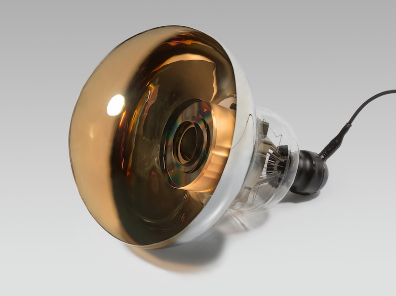
| Requirements | Value | Conditions | |
|---|---|---|---|
| Photon detection efficiency | 26% | Typ. | Quantum Efficiency Collection Efficiency |
| around 400 nm wavelength | |||
| (10%) | (including Photo-Coverage on the inner detection area) | ||
| Timing resolution | 5.2 nsec | FWHM, Typ. | Single Photoelectron (PE) |
| Charge resolution | 50% | , Typ. | Single PE |
| Signal window | 200 nsec | Max. | Time window covering more than 95% |
| of total integrated charge | |||
| Dynamic range | 2 photons/cm2 | Min. | Per detection area on wall |
| Gain | Typ. | ||
| Afterpulse rate | 5% | Max. | For single PE, relative to the primary pulse |
| Rate tolerance | 10 MHz | Min. | Single PE pulse, within 10% change of gain |
| Magnetic field tolerance | 100 mG | Min. | Within 10% degradation |
| Life time | 20 years | Min. | Less than 10% dead rate |
| Pressure rating | 0.8 MPa | Min. | Static, load in water |
The OD photosensor design is based on the Super-K OD photosensor, the 20 cm Hamamatsu R5912 PMT, with an improved high quantum efficiency photocathod and a hard waterproofing cover to stand the 60 m deep water pressure in Hyper-K.
This section describes the characteristics of these photosensors. In addition, we present prospects for alternative options, which may be adopted in future.
II.2.6.2 Photosensor for Inner Detector
II.2.6.2.1 Performance
A newly developed 50 cm R12860-HQE PMT (HQE, high quantum efficiency) for Hyper-K by Hamamatsu (hereafter referred to as the HQE B&L PMT), has a faster time response, better charge resolution and a higher detection efficiency with a stable mechanical structure, compared to the existing large aperture PMTs. This section describes the specifications of the HQE B&L PMT, as well as the safety design that ensures longevity of operation.
II.2.6.2.1.1 Design and Specifications
Figure 58 shows a side view of the HQE B&L PMT, whose shape is similar to the PMT used in Super-K. Hence, the support structure developed in Super-K to attach the PMT is also appropriate for the HQE B&L PMT in Hyper-K. The dynode structure and the surface curvature were improved. A typical bias voltage of 2,000 V is divided to each dynode by a PMT base circuit such the one shown in Figure 59. The specifications for a typical HQE B&L PMT is listed in Table 18.


| Shape | Hemispherical |
|---|---|
| Photocathode area | 50 cm diameter (20 inches) |
| Bulb material | Borosilicate glass ( mm) |
| Photocathode material | Bialkali (Sb-K-Cs) |
| Quantum efficiency | 30 % typical at nm |
| Collection efficiency | 95 % at gain |
| Dynodes | 10 stage box-and-line type |
| Gain | 107 at V |
| Dark pulse rate | kHz at gain (13 Celsius degrees, after stabilization for a long period) |
| Weight | 9 kg (without cable) |
| Volume | 61,000 cm3 |
| Pressure tolerance | 1.25 MPa water proof |
II.2.6.2.1.2 Detection Efficiency
The single photon detection efficiency of the HQE B&L PMT is a factor of two better than the conventional R3600 in Super-K (Super-K PMT). Figure 60 shows the measured quantum efficiency (QE) of several HQE B&L PMTs as a function of wavelength compared with a typical QE curve of the Super-K PMT (dotted line). The QE of the R12860-HQE PMT is typically 30% at peak wavelength around 390 nm, while the peak QE of the Super-K PMT is about 22%.

The HQE B&L PMT has a high collection efficiency and large sensitive photocathode area. The photocathode area with a collection efficiency (CE) of 50% or better is 49.2 cm for the HQE B&L PMT, compared to 46 cm in case of the Super-K PMT and 43.2 cm in the KamLAND PMT. Compared with 73% CE of the Super-K PMT within the 46 cm area, the HQE B&L PMT reaches 95% in the same area and still keeps a high efficiency of 87% even in the full 50 cm area. This high CE was achieved by optimizing the glass curvature and the focusing electrode, in addition to the use of a box-and-line dynode. In the Super-K Venetian blind dynode, the photoelectron sometimes misses the first dynode while the wide first box dynode of the box-and-line accepts almost all the photoelectrons. This also helps improving the single photoelectron (PE) charge resolution, which then improves the hit efficiency at a single PE level. By measuring the single PE level, we confirmed the CE improvement by a factor of 1.4 compared with the Super-K PMT, and 1.9 in the total efficiency including HQE. Figure 61 shows that the CE response is quite uniform over the whole PMT surface despite the asymmetric dynode structure.
A relative CE loss in case of a 100 mG residual Earth magnetic field is at most 2% in the worst direction, or negligible when the PMT is aligned to avoid this direction on the tank wall. The reduction of geomagnetism up to 100 mG can be achieved by active shielding by coils.

II.2.6.2.1.3 Performance of Single Photoelectron Detection
The single photoelectron pulse in a HQE B&L PMT has a 6.7 nsec rise time (10% – 90%) and 13.0 nsec FWHM without ringing, which is faster than the 10.6 nsec rise time and 18.5 nsec FWHM in the Super-K PMT. The time resolution for single PE signals is 1.1 nsec in for the fast left side of the transit time peak in Figure 63 and 4.1 nsec at FWHM, which is about half of the Super-K PMTs. This would be an important factor to improve the reconstruction performance of events in Hyper-K.
The nominal gain is and can be adjusted for several factors in a range between 1500 V to 2200 V. Figure 63 shows the charge distribution, where the 35% resolution in of the single PE is better for the HQE B&L PMT compared to the 50% of the Super-K PMT. The peak-to-valley ratio is about 4, defined by the ratio of the height of the single PE peak to that of the valley between peaks.
![[Uncaptioned image]](/html/1805.04163/assets/x80.png)
![[Uncaptioned image]](/html/1805.04163/assets/x81.png)
|
II.2.6.2.1.4 Gain Stability
Because the Hyper-K detector aims for various physics subjects in a wide energy range, the PMT is required to have a wide dynamic range. The Super-K PMTs have an output linearity up to 250 PEs in charge according to the specifications and up to about 700 PEs as measured in Super-K (with up to 5% distortion) Abe et al. (2014f), while the linearity of the HQE B&L PMT was measured to be within 5% up to 470 PEs as seen in Figure 64. Even with more than 1,000 PEs, the output is not saturated and the number of PEs can be calculated by correcting the non-linear response. The linearity range depends on the dynode current, and can be optimized by changing the resistor values in the PMT base circuit. This result demonstrates sufficient detection capabilities in the wide MeV – GeV region as in Super-K, as long as it is corrected according to the response curve.

A fast recovery of gain for high signal rate is needed for supernova observation, decay electrons from muons, and any accidental pileup events. On the other hand, separation of individual signals in time is limited by the charge integration range, that is 200 nsec (equivalent to 5 MHz) or more depending on the electronics.
The rate dependence of the output charge was measured at several light intensities while varying the constant interval time of light pulses (as shown in Figure 66). A 5% drop is observed at the output current of 170 A. It corresponds to 78 MHz in the single PE intensity or 1 MHz in most of detected intensities like at the level of few tens of PE. This is sufficient to detect possible burst physics events (Section III.3.1).
![[Uncaptioned image]](/html/1805.04163/assets/x83.png)
|
Even when two near continuous events are detected, like in the case of an event with a decay particle, no loss of charge was observed for the second delayed pulse. By measuring two continuous pulses of about 150 PEs in both, the observed loss of gain is stable within 0.5% as shown in Figure 66. Therefore, the output charge fidelity for a delayed signal is sufficient with the HQE B&L PMT.
A long term stability test was performed on three HQE B&L PMTs in a 200 ton water Cherenkov detector at the Kamioka mine, which was constructed to evaluate the feasibility of anti-neutrino tagging via gadolinium doping in water. All the HQE B&L PMTs functioned over two years, and the gain measured using the charge peak resulting from a pulsed calibration source was stable within 1% RMS (Figure 67).

II.2.6.2.1.5 Backgrounds
The dark hit rate originates from a thermionic emission on the photocathode, and depends on the environmental temperature, the bias high voltage and the accumulated operating time for stabilization. For Hyper-K, the energy threshold for low energy physics studies depends largely on the PMT dark hit rate, because the sum of the PMT dark hits create fake event triggers.
The dark hit rates of several HQE B&L PMTs were measured to be 8.3 kHz at a temperature of 15 ∘C in air after a month-long stabilization period. The adequacy of this dark hit rate on the physics sensitivities will be discussed in Section III. Since the detection efficiency is doubled for the HQE B&L PMTs, the obtained current dark hit rate is relatively high compared to the Super-K PMT (4.2 kHz). A lower dark rate results in a better sensitivity to low energy events, thus the HQE B&L PMT production is being optimized to achieve a lower dark hit rate. We expect further improvements within the next year.
The afterpulse has a long delay of several microseconds order after the primary PE, and can result in mis-reconstruction for tagging delayed particles. Afterpulsing is caused by a feedback of the ionized residual gas to the photocathode, and several timing peaks appear due to the different gas molecular masses. As shown in Figure 68, hit timing distribution of the HQE B&L PMT has several peaks of afterpulses. The afterpulse rate is, in total, less than 5% relative to the main pulse at single PE observation. It is comparable to the Super-K PMT.

The radioactive contamination in the surface glass was measured by a germanium semiconductor detector. It is listed in Table 19 by Uranium series, Thorium series and Potassium-40. The contamination of Potassium-40 was reduced by an order of magnitude compared to the glass used in the Super-K PMT.
| U-chain | Th-chain | K40 | |
|---|---|---|---|
| Bq/kg | 5.4 | 1.8 | 1.6 |
| Bq/PMT | 34.5 | 11.3 | 10.5 |
II.2.6.2.2 Mechanical Characteristics
The HQE B&L PMT bulb has been improved and proven to survive under 60 meter water for Hyper-K as described in this section. It is sufficiently better than the Super-K PMT, which is only specified for 40 meter deep water.
However, with the large number of photosensors in Hyper-K we expect that even with a pre-selection (using a quick pressure test, etc.) before installation, it is difficult to ensure that there is no glass failure. In 2001, a chain implosion of 6,779 PMTs out of 11,146 took place at Super-K. It was triggered by an accidental implosion which was transmitted to other PMTs as pressure pulse. In order to avert a similar accident, a protective cover made of a ultraviolet (UV) transparent acrylic cover for the detection area and a Fiber Reinforced Plastics (FRP) for the rear was introduced in Super-K.
Such a protective cover is needed to avoid any cascade implosion of the photosensors, making up for the difficult control of the glass quality in the production. The cover was re-designed to further reduce the impact of pressure pulse, because a 60 meter water depth boosts the peak pressure caused by the implosion by a factor of 1.6 from Super-K, corresponding to 6–7 MPa. The new design of the ID photosensor cover and its validation are explained in this section.
II.2.6.2.2.1 Design and Confirmation Test
The weakest point of the Super-K PMT, which is around the largest reverse curvature (Neck in Figure 69), was improved for the HQE B&L PMT. Based on a stress analysis, the first bulb shape, R12860-A, was designed to reduce the stress concentration around the neck. Further improvement was achieved in R12860-B by optimizing the curvature because there was a crack observed on the photocathode surface of R12860-A (in Figure 69) after a high pressure water test.

To validate the degree of improvement, a dedicated test of the PMT in water under high pressure was performed. In a high pressure vessel filled with water, one PMT was tested by increasing the pressure in steps of 0.1 MPa above 0.5 MPa and waiting for 7 minutes in each step.
At first, we tested 35 samples of the initial prototypes (R12860-A), and the depth range of implosion or crack was between 70 and 155 meters pressure water (Figure 71). According to a survey of the glass thickness before the test, samples that imploded around a shallow depth of 70–100 meters were found to have a relatively thin thickness of around 2.0–2.5 mm at the thinnest point as in Figure 71. To mitigate this, a quality control step will be introduced whereby we measure the glass thickness and reject bulbs with thin thicknesses. The glass quality, in regards to bubbles, foreign matter, cracks and thickness, is expected to be enhanced after improved training in bulb blowing over the year prior to mass production.
The R12860-B PMT improved with the new shape was also tested. 21 R12860-B PMTs out of the total 25 did not implode up to 1.5 MPa (150 m equivalent) as shown in Figure 71. All tested PMTs had sufficient high pressure resistance for the 60 meter water depth of Hyper-K. It should be noted that the test performed this time was in several different conditions of PMT length or waterproofing, in order to find the best design with high pressure bearing.
One of the two PMTs that imploded did so between 1.2 and 1.3 MPa (120 m and 130 m equivalent). This PMT had the smallest measured glass thickness around the neck out of all of the 25 tested R12860-B PMTs. Another PMT formed crack around the metal pins in the back, which the stress analysis determined to be the weakest part in the R12860. This PMT had a waterproofed guard cover around the pins with the same design as the R3600’s, and its Polyethylene material is not sufficiently hard to guard the glass against the high pressure water that exists above 1 MPa level. Thus, the guard cover was improved with a new hemisphere design made of PPS (Poly Phenylene Sulfide) resin and adopted for a subsequent test of fifty PMTs.
![[Uncaptioned image]](/html/1805.04163/assets/x88.png)
![[Uncaptioned image]](/html/1805.04163/assets/x89.png)
|
II.2.6.2.2.2 Quality Control of the PMT Glass Bulb
The glass bulb is manufactured by hand; therefore it is difficult to expect uniform thickness throughout the mass production. In order to find an indication of a possible failure, the glass thickness was checked by an ultrasonic thickness gauge at various measurement points. As indicated in Figure 71 there exists a relation between the glass thickness and failure pressure, and therefore screening PMTs based on glass thickness would be effective to minimize the failure. Also the bulb was inspected by eye to find unexpected cracks, foam and foreign matter.
Eventually after the production, individual PMTs will be tested before installation. It is planned to load a high pressure in water over a few minutes before the installation to the Hyper-K tank, in order to reject a bad bulb. In case of Super-K, 4,727 PMTs were checked with 0.65 MPa high pressure water to be safely used up to 40 m water depth for the reconstruction after the accident. Sixteen PMTs of 4,727 were rejected using the test, that is 0.3% fraction.
Before the mass production of photosensors starts, we aim to establish the quality control criteria. We performed a screening test using fifty of the R12860 PMTs, in order to set the best criteria that we will use for the mass production.
-
•
Remarkable failures such as bubbles, foreign matter and striae were recorded and photographed during the quality check to measure the size and to count the number of occurances.
-
•
The glass thickness was measured at 57 points.
It is noted that the photocathode and dynode are absent, but it does not matter because we only investigated the mechanical characteristics without measuring the detection performance. Similar to the screening performed in Super-K, we tested all fifty PMTs in a high pressure water vessel. At this time, the load pressure is assumed to be 0.95 MPa for the use in 60 meter water corresponding to 0.65 MPa for 40 meter in Super-K. So far, fifty PMTs were tested after the production and there was no damage at 0.95 MPa. All of the fifty PMTs were also tested up to 1.25 MPa for further investigation, but here we also found no damage in all PMTs.
According to this test, the selection criteria and condition is optimized. In the 2017 fiscal year, we will test 140 functional PMTs and will apply the criteria that will be used in Hyper-K. Although the bulb design of the R12860 PMT is same as the previous test, the production will be improved as below.
-
•
The metal mold is renewed.
-
•
The amount of glass is controlled by an automated machine to reduce variations in glass thickness.
-
•
The automated measurement system of glass thickness is available for the precise and quick screening.
II.2.6.2.2.3 Degradation of the PMT Glass Bulb
As for a degradation of the glass material, the HQE B&L PMT uses stable glass made of borosilicate like Super-K, which is highly resistant to an aqueous corrosion. A general pressure cooker test for the glass plate, in 100% humidity air at 121∘C and 0.2 MPa for 17 hours, showed almost no optical degradation, where the largest degradation is about 1% only seen at around 350 nm wavelength and negligibly small. A test to immerse a glass powder in 98∘C boiled pure water for an hour showed a small 0.03% dissolution in weight, which is very low compared to existing glass.
Mechanical characteristics were evaluated at four different points on the PMT using PMT sampling glass taken from the bottom of the Super-K tank after 5-years of running. A composition ratio of material and bending strength are surveyed, and found to be comparable with other Super-K PMTs stored in air at atmospheric pressure. The high pressure test was also performed on nine sample PMTs from Super-K – three each from the top, bottom and barrel sections after 5-years in water – and there was no implosion with a 0.65 MPa load.
To examine the possibility of degradation by glass crystallization, the glass surface was surveyed using X-ray diffraction at the four different points as well. There was no diffraction peak originating from the crystallized glass, in either of the two samples; one stored in air and the other from the bottom of Super-K.
The number of dead channels of the ID photosensors is 0.4% after seven years of Super-K operation, including the ones with wrong cable connections. It might also include PMTs with an unknown crack or implosion, and therefore we would expect a similar rate of glass damage in Hyper-K, 1% at maximum for twenty years.
It is concluded that the borosilicate glass used in the HQE B&L PMT is expected to have stable material characteristics over twenty years, and several mechanical tests using the Super-K PMTs could find no degradation in the long run. The mass production and selection should be well managed such that the physical damage rate is suppressed to the 1% level. This level of failure is acceptable because the protective cover will avoid a chain implosion.
II.2.6.2.2.4 Shockwave Prevention Covers for PMTs
Necessity of PMT covers
As described in previous sections, every effort has been and will be made to avoid a PMT implosion inside the Hyper-K water tank. Based on the knowledge of the mechanical characteristics of the Super-K PMT, the new 50 cm PMT has been designed to have enough strength for the safe use at a water depth of 60 m, and its performance has been demonstrated by hydrostatic pressure tests. The production of the forty thousand PMTs for Hyper-K will be carried out under a strict quality control, and the total inspection of the products including a pressure test will get rid of any individual PMTs having a higher risk of an implosion before their installation.
However, the possibility of a single PMT implosion cannot be zero. To prevent a chain reaction of imploding PMTs caused by the failure of a single one, all PMTs in Hyper-K are housed in the shockwave prevention covers, similar to those installed on the 50 cm PMTs in Super-K after the catastrophic accident.
Basic design concept
The PMT cover for Hyper-K is designed on the same basic concept as that for the Super-K PMT cover design. In both detectors, the PMT cover has several small holes, and the gap between the PMT surface and the cover is filled with the tank water. Since the covers themselves are not usually exposed to the water pressure, there is no need to care about any deformations caused by a long-term exposure to the high water pressure. On the other hand, the PMTs are constantly exposed to the water pressure. In the unlikely event of an imploding PMT, the water pressure is immediately applied to the cover housing the broken PMT. The tank water slowly flows in through the small holes on the cover and fills up the vacuum region made by the PMT implosion. The PMT cover is designed to have enough strength so that it can keep its shape even in such a case. Therefore, the peak amplitude of the pressure shockwave is significantly reduced outside the PMT cover and thus cannot cause a chain reaction.
Super-K PMT covers
In developing the Super-K PMT cover, there were strict restrictions on its weight and shape, since the PMT supporting framework constructed in the tank had originally been designed to support the bare PMTs. Among three major candidate designs, the PMT cover formed by combining an acrylic front window and a backside cover made of fiber-glass reinforced plastic (FRP) was selected in Super-K, since it had been demonstrated by a hydrostatic test and a PMT implosion test that the cover would not be crushed even if the PMT inside would implode. Thus, the Super-K group decided that the combination of the acrylic and FRP parts with flange coupling bolts was suitable for a possible future PMT replacement work and that the components can be readily produced.
A cover formed by combining two half bodies of a molded acrylic product was another candidate. This full-acrylic cover also was found to have enough mechanical strength for withstanding the water pressure in the case of a PMT implosion, but it was not adopted due to its mass production difficulty, a higher manufacturing cost and uncertainty of the strength when combining two bodies.
A cover composed of an acrylic front cover and a stainless steel (SUS) backside cover was also a candidate. The reproducibility of its shape and thickness is better than those of FRP cases. The SUS cover with a thickness of 2 mm could not pass a PMT implosion test, while PMT covers with a thicker SUS component were not possible due to the restriction on the cover weight in Super-K,
Cover design selection for Hyper-K
Since the depth of the Hyper-K water tank (60 m) is about 1.5 times larger than that of the Super-K water tank (41.4 m), the Hyper-K PMT covers have to withstand a higher pressure in the case of an implosion of the PMT inside. The three cover designs which had been studied for Super-K (i.e. acrylic+FRP, full acrylic, and acrylic+SUS covers) can be also candidates for the Hyper-K PMT cover.
However, it is now known that FRP does not just contain much more radioisotopes than those in the PMT glass but FRP itself also emits light via chemiluminescence, as observed in Super-K. Since these unwelcome things can produce more background events for low energy physics, we have decided not to use any FRP-made covers in Hyper-K. As for the PMT cover formed by a molded acrylic product, there are still the problems such as a higher cost for an initial prototype. If these problems could be solved within a reasonable time scale, the full-resin cover can be an alternative design for Hyper-K.
The cover made of the stainless steel contains less radioisotopes and is suitable for mass production. Unlike the Super-K case, in which SUS-made PMT covers were not adopted due to the weight limit coming from the existing tank framework specification, the Hyper-K tank framework can be designed so that it can support the PMT system including the SUS covers of a sufficient strength. Therefore, we have adopted the PMT cover design of a combination of acrylic and SUS components for Hyper-K.
Hyper-K cover design

Figure 72 shows the shape of the Hyper-K PMT cover. The front-side cover with a partial spherical shape is made of a UV transparent acrylic with thicknesses of 11 mm at the center position and 15 mm at the flange part (Figure 73), which is about 1.2 times thicker than the acrylic part of the Super-K PMT cover. The light transmittance of the acrylic cover measured in water is more than 95% for a wavelength longer than 350 nm, which is reasonably good considering the quantum efficiency of the 50 cm Hyper-K PMT. Since the section modulus is proportional to the square of the thickness, the Hyper-K acrylic cover could have about twice the strength of the Super-K one, though this is just a crude estimation. The backside cover with a combination of ring and circular truncated cone shapes is made of stainless steel with a thickness of 3 mm. The front acrylic part and the backside SUS part are connected to each other by flange coupling bolts.
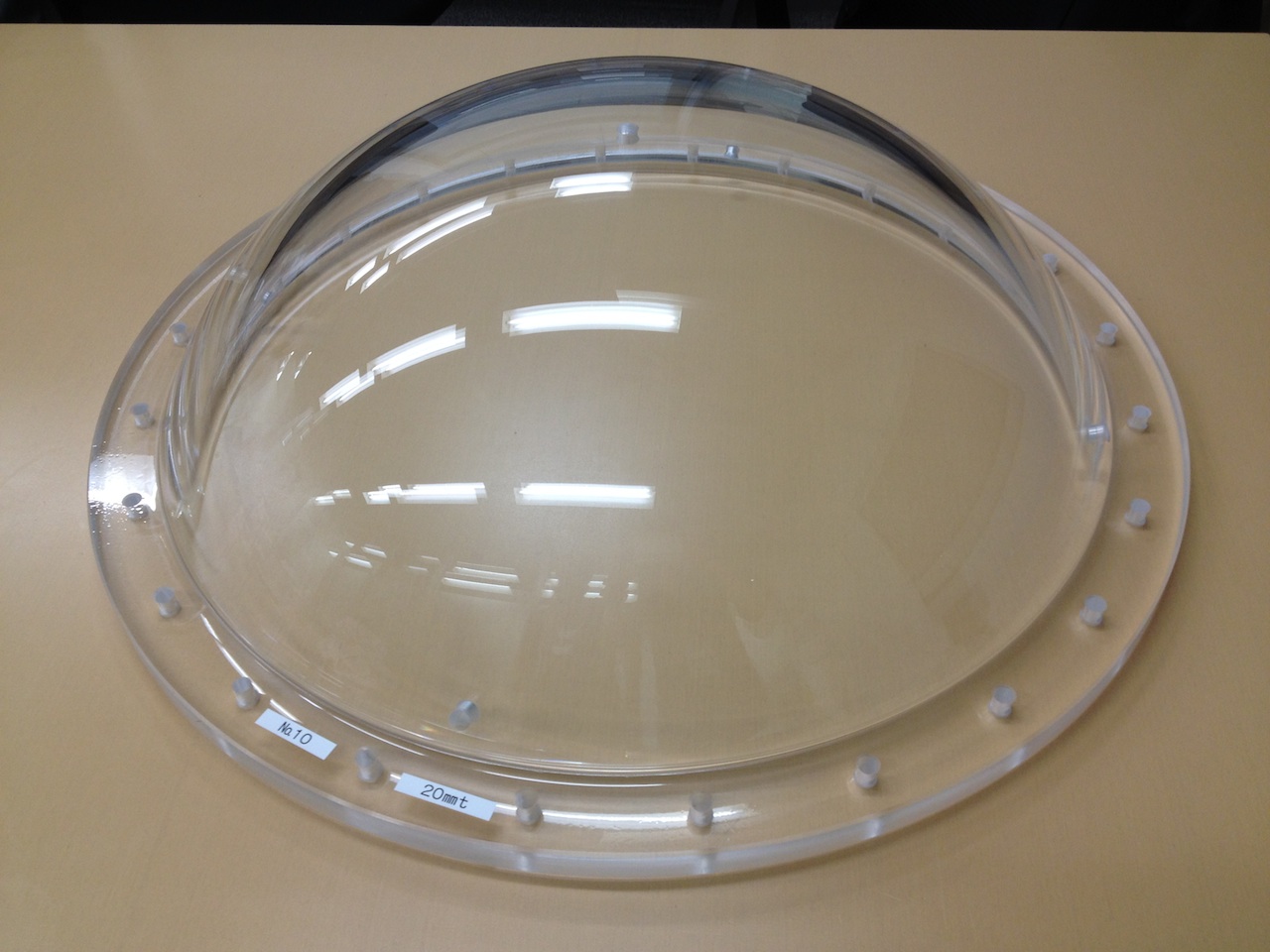
The detailed design of the cover, such as a thickness of each part, has been determined based on a dynamic behavior analysis, simulating the situation after a PMT implosion. The analysis has shown that the PMT cover of the design mentioned above will not be crushed even if the PMT inside would implode at a water depth of 100 m. The PMT implosion simulation should have some uncertainties, but we think they cannot change the conclusion that the cover will be functioning well at the depth of 60 m. This was confirmed by the performance demonstration tests described later.
On the acrylic cover, five holes with a diameter of 10 mm are formed; one at the center and four near the flange. These number, diameter and position of the holes on the acrylic cover are the same as those for the Super-K PMT cover. In developing the Super-K PMT cover, the soundness of the holes on the acrylic cover against the water stream caused by a PMT implosion had been checked. The test had shown that the holes were not affected when exposed to a water stream with a hydraulic pressure of 0.65 MPa. Therefore, the hole design should be sufficient for the Hyper-K PMT cover.
It is measured that acrylic is degraded to 77% by water absorption. Therefore, if it is confirmed by the PMT implosion test at 80 m that the covers have enough performance to prevent a chain implosion of PMTs, they are expected to be functioning for the duration of the Hyper-K lifetime.
II.2.6.2.2.5 Demonstration Test of Shockwave Prevention Covers
The Hyper-K PMT cover has been designed so that it will not be crushed in the unlikely event of a PMT implosion and will prevent the occurrence of the shockwave causing a chain reaction of imploding PMTs. To measure the performance of our PMT cover, we carried out two tests. First, we carried out a hydrostatic pressure test of the PMT cover in Kamioka Mine to ensure the mechanical strength. In this test, PMT cover was wrapped by a waterproof plastic bag and set in a high pressure vessel filled with water. We pressurized the water surrounding the PMT cover, and the test showed that our PMT cover stood up to 1.1 to 1.5 MPa as it was designed.
Next we carried out a prevention of the chain reaction of implosion with a mock-up of the PMT array of Hyper-K. We utilized a test site formally used by Japan Microgravity Center (JAMIC), in Kami-Sunagawa, Hokkaido, Japan, for our chain implosion test. The site has a vertical shaft depth of about 700 m with about 4 m diameter, filled with spring water.
In the test, nine PMTs were aligned 3 3 and mounted on a framework with same 70 cm spacing in the Hyper-K inner detector. Figure 74 shows the photograph of the mock-up just before sinking to deep water. The central PMT was housed in the PMT cover, and implosion of the central PMT in the cover was induced by the apparatus which was designed to hit and crash the PMT remotely. The others were bare to confirm there is no damage by a shockwave of the implosion at the center.

This mockup was sunk into the deep water (60 m or 80 m) with pressure gauges and high-speed camera. Three trials for each depth were done, and we found that the pressure was reduced to less than 1/100 and the cover was not crushed. Figure 75 shows the measured pressure at the front of the central PMTs for each test at 60 m water depth. The PMTs surrounding the center one were used in the second and third tests, but no damage was incurred due to a sufficient suppression of the shockwave by the central cover. We conclude that our PMT cover works to prevent the chain implosion in both 60 m and 80 m water depths.


We successfully established the cover design for Hyper-K using these tests. In order to reduce cost and weight, improvement of the cover is on-going and several alternative ideas are under study.
II.2.6.2.2.6 Summary

The strength of the PMT bulb was enhanced by the improved bulb design, quality check and pre-test in the high pressure vessel before the installation. A schematic flow diagram of various measures to avoid a chain reaction of imploding PMTs is summarized in Figure 76. In general, it is hard to expect there will be no implosion in Hyper-K over the decades-long operation. Thus, the protective cover is conservatively designed to avoid any chain implosion by suppressing the shockwave, and this design will be tested in advance of final production.
II.2.6.3 Photosensor for the Outer Detector
The primary function of the Outer Detector is to reject the incident cosmic ray muons that make up part of the background in the measurement of nucleon decays and neutrino interactions occurring in the Inner Detector. The photosensor design for the Hyper-K Outer Detector will be similar to that of the successful Super-K Outer Detector using 20 cm Hamamatsu R5912 PMTs. The OD PMT array is sparse relative to the ID PMT array, resulting in a 1% photocathode coverage on the inner wall of the OD. To improve the light collection efficiency by about a factor of 1.5, an acrylic wavelength shifting plate of a 60 cm 60 cm square shape is placed around the glass bulb of each of the 20 cm OD PMTs.
The pressure tolerance tests have demonstrated that R5912 PMTs could withstand the water pressure at a depth of 60 m. For Hyper-K, the R5912 was improved using PPS resin for the guard cover like the R12860 PMT, as shown in Figures 78 and 78. It also has improved high quantum efficiency of 30%
![[Uncaptioned image]](/html/1805.04163/assets/design-photosensor/figures/photosensor_8pmtassy2.png)
![[Uncaptioned image]](/html/1805.04163/assets/design-photosensor/figures/R5912HQEpic.jpg)
|
In Super-K, there is no cover attached to the 20 cm OD PMTs. It is noted that the volume of the 20 cm PMT bulb is 6% of the 50 cm one, with the similar glass thickness and far distance among OD PMTs. Because of the 60 m deep water level compared with Super-K, we would reconsider a safety use of the PMT and cover with appropriate evaluation and tests such as implosion.
II.2.6.4 Alternative Designs
There is still room to improve the Hyper-K performance with new possible photosensors which are under development. The key of the alternative options is to show sufficient or superior physics sensitivities while demonstrating safe use in the water tank over a long period of time at a reasonable cost. All the listed alternative candidates are expected to be ready before the Hyper-K construction period, but are currently shown as options because the product design is not finalized.
II.2.6.4.1 50 cm High-QE Hybrid Photodetector
Another new 50 cm photosensor with the better time and charge resolution than the existing 50 cm photosensors is a combination semiconductor device, called a hybrid photodetector (HPD), and is made by Hamamatsu (R12850-HQE).
The HPD uses an avalanche diode (AD) instead of a metal dynode for the multiplication of PEs emitted from a photocathode. A simple AD structure will have good quality control in mass production, and a lower production cost than the complex of metal dynodes. In order to collect PEs in a small 20 mm diameter area of the AD, a high 8 kV is applied. Related items such as the cable, connector and power supply were also developed.
Figure 80 shows that electrons are multiplied by a factor of with a combination of a bombardment gain and then avalanche gain. The gain is adjusted by the bias voltage applied on the AD, around a few hundred volt, while the 8 kV is fixed. The HPD is equipped with a pre-amplifier, so the resulting gain is equivalent to PMTs. The size and surface material are almost the same as those of the 50 cm PMT as shown in Figure 80, thus the same support structure and protective cover can be used.
![[Uncaptioned image]](/html/1805.04163/assets/x95.png)
![[Uncaptioned image]](/html/1805.04163/assets/x96.png)
|
The single PE detection is significantly better, though it is still limited by the pre-amplifier because of a large junction capacitance of the AD (400 nF). The transit time spread at single PE is 3.6 nsec in FWHM measured at the fixed threshold, as drawn by the red line in Figure 82. It is superior to 7.3 and 4.1 nsec for the Super-K PMT (black) and B&L PMT (blue), respectively. With the time walk correction using measured charge, the HPD resolution reached 3.2 nsec in FWHM as shown by the dotted magenta line.
Figure 82 shows the 15% charge resolution of the HPD as the standard deviation at the single photoelectron peak as in the red line. It is superior to both the 53% and 35% for the Super-K PMT (black) and B&L PMT (blue). If the AD is segmented into two channels as a test, individual readout of HPD showed better resolution of 10% as shown by a dotted line due to a half junction capacitance. Further five segmentation into a center channel and surrounding four channels brings a position sensitive detection with considering a hit probability in five channels by a slight focusing shift by different arrival points of photons on the glass. It might help a good event reconstruction and background rejection.
![[Uncaptioned image]](/html/1805.04163/assets/x97.png)
![[Uncaptioned image]](/html/1805.04163/assets/x98.png)
|
The waterproof HPD was successfully operated for 20 days in a dark box filled with water as shown in Figure 83. In very near future, the HPD would be a superior option to the PMTs, after successful long-term tests of all performance and usability criteria.

II.2.6.4.2 Smaller Photosensors
Photosensors with a 20–30 cm aperture can also be an alternative option. These are available with the HQE and by another manufacturer. Using two small photosensors are comparable to a single 50 cm photosensor as for the detection efficiency, or a little larger aperture size than the 20 cm photosensor can be considered as the OD photosensor. A smaller 7.7 cm PMT with a large photo-collection plate is also a possible alternative option with a low cost for the OD photosensor system.
II.2.6.4.2.1 20–30 cm High-QE PMTs
Based on the successful development of the 50 cm HQE B&L PMT, 20 cm or 30 cm PMTs can obtain superior performance compared to the existing small PMTs. By applying the same techniques, the 20 cm and 30 cm PMTs with a high QE box-and-line dynode and improved performance will be available easily by scaling the 50 cm PMT down with a similar design. The performance is expected to be equivalent or better compared with the 50 cm HQE B&L PMT.
Prior to that, the HQE 30 cm PMT, R11780-HQE by Hamamatsu, was developed aimed at a large water Cherenkov detector planned in US for the LBNE project. It reached a QE of 30% and pressure rating over 1 MPa. Further improvement was tried, and a new bulb design of the HQE 30 cm PMT based on the R12860-HQE and R11780-HQE was made. In order to validate the high pressure tolerance, a test in a high pressure water was performed on three samples at Kamioka. As a result, all the samples got no implosion up to 150 meter water equivalently.
Until recently, photomultiplier tubes with an aperture over 25 cm have been almost exclusively supplied to the market by Hamamatsu. It is important that additional vendors come in the marketplace for price competition and for additional supply capacity.
ET Enterprises Limited ADIT, now a US-based PMT manufacturer in Texas, has been developing a large area PMT, financially supported by NSF. Testing of the operational first generation 28 cm HQE PMTs have been performed at Pennsylvania, UC Davis, etc. showing comparable efficiency and charge measurement performance to those of similarly-sized Hamamatsu HQE PMTs.
If successfully produced, the PMTs can be a cost-effective alternative to Hamamatsu for Hyper-K OD PMTs.
II.2.6.4.2.2 7.7 cm Photodetector Tube
In this section we will focus on an alternative design of the outer-detector using the 7.7 cm photosensors. It is expected that the costs will be lower than the nominal configuration as well as also providing an extended market and production capacity. At the moment the nominal configuration of the outer-detector consists of an array of 20 cm hemispherical photosensors placed on a grid to reach a photo-coverage of 1%, as represented in Fig. 38. These photosensors are mounted on wavelength shifting plates, to improve the light collection.
By using 7.7 cm photosensors instead of the 20 cm, the number of photosensors is multiplied by six to keep the same coverage. The photosensors are therefore closer to each other thus increasing the number of hits collected, and improving the coincidence accuracy. Moreover, the outer-detector water thickness is about 1 m, and particles will produce less light and in a narrower region — compared to the Super-Kamiokande detector where the outer-detector water thickness is about 2 m. Thus, a setup with more photosensors closer to each other should allow a better sensitivity, especially with the configuration of Hyper-Kamiokande with a reduced water thickness.
We are currently testing candidate 7.7 cm photosensors to be used in the outer-detector, see Fig. 84 for the teststand, as well as implementing the outer detector in that simulation and reconstruction, which is needed for optimizing the configuration.

Our tests have been performed using the ET9302KB and other photosensors. The ET9302KB was extensively tested and many of its parameters measured. It has a QE of 30% and a small dark current rate which has been measured at 400 Hz — about ten times less than typical rates for 20 cm photosensors — and a small after-pulse rate with respect to the gain.
The ET9302KB would fit perfectly in a configuration with several photosensors like the outer detector, since the number of accidental coincidences inherently raised by the amount of photosensors used will be reduced thanks to its low-noises properties.
Furthermore, these photosensors also showed excellent linearity and resolution, allowing an accurate reconstruction of the energy of the particles inside the outer-detector. Figure 85 shows the linearity of the photosensor, where deviation was measured to be of the order of 1%. The resolution at 1000 photoelectrons collected — which is what is expected for a few-MeV gamma event for example — is measured to be 2%.

The newly improved photosensor from ET Enterprises Ltd., D793KFLB, with a transit time spread of 1.6 nsec, a nominal gain at 850–1100 V and nominal dark rate 1000 Hz at 800 V is currently under test. Preliminary results showed excellent linearity and resolution.
The photosensors are hemi-spherical and will also be mounted on wavelength shifting plates, which allow an easy way to enhance the light collection. Wavelength shifting plates will reemit the absorbed photons in the direction of the photo-cathode of the photosensors at a wavelength around 400 nm, where the quantum efficiency of the ET9302KB is maximum.
Outer detector alternative configurations with 7.7 cm photosensors will be evaluated in simulation and the best setting will be selected accordingly, using realistic cosmic flux files from the Super-K collaboration to test the performance.
The chosen configuration should achieve at least the minimum detection efficiency to have sufficient ability to veto cosmic rays or catch through-going particles.
Finally, also another alternative of using 12.7 cm photosensors, i.e. an intermediate solution between 7.7 cm and 20 cm photosensors, is planned to be addressed in both the optimization in simulation of the configurations and in testing the photosensors.
II.2.6.4.3 Multi-PMT Optical Module
The concept of an optical module with a 20 to 40 cm PMT housed in a glass pressure vessel has been developed the past decades for neutrino telescopes in water and ice (DUMAND Babson et al. (1990), Baikal Belolaptikov et al. (1997), NESTOR@ Rapidis et al. (2009); E.G.Anassontzis et al. (2002), ANTARES Ageron et al. (2011); Amram et al. (2002), AMANDA Braun et al. (2009) and IceCube Achterberg et al. (2006)). For KM3NeT KM3Net Consortium , the km3 neutrino observatory under construction in the Mediterranean, a single large area phototube has been replaced by 31 7.7 cm PMTs packed in the same glass pressure vessel. This new fly’s eye photosensor concept, in which small PMTs replace a single PMT, has been dubbed the “multi-PMT Optical Module (mPMT)”. The mPMT has several advantages as a photosensor module:
-
•
Increased granularity
The increased granularity of mPMT provides enhanced event reconstruction, in particular for multi-ring events, such as in proton decays and multi-GeV neutrinos which is important for mass hierarchy studies, and for events near the wall where fiducial volume is defined. Since each of the PMTs have different orientations with limited field of views, the mPMT carries information on the direction of each detected photon. This directional information effectively reduces the dark hit rate since the dark hits only applies to the field of view of the PMT. As a result, it improves signal-to-noise separation for low energy events such as solar/supernova neutrinos and the neutron tagging as discussed in Section III.2.2. -
•
Mechanically safe pressure vessel with readout and calibration integrated
The pressure vessel protect against implosion. Since the vessel is filled with small PMTs, electronics and the support structure without large void, shock waves would be suppressed even when implosion takes place. The pressure vessel contains digitization electronics and calibration sources, providing natural solutions for readout and calibrations. -
•
Cost, geomagnetic field tolerance, and fast timing for 7.7 cm PMT’s
Economical mass-production of 7.7 cm PMT’s in particular for medical use provides almost the same cost per photocathode area for 7.7 cm PMT compared to larger PMTs. For example, KM3NeT claims the cost per photocathode area is cheaper than for the 20 to 40 cm PMTs. Additional advantages of small PMTs are their much lower sensitivity to the Earth’s magnetic field, which makes magnetic shielding unnecessary V.Giordano et al. (2015), and potentially better timing resolution, which could further reduce the dark hit background and event reconstruction. The failure rate of small PMTs is of the order of 10-4/year. Any loss of a single PMT would affect the detector performance minimally compared to the loss of one large area PMT. -
•
Complex structure, an opportunity for international contributions
A potential draw back of mPMT compared to off-the-shelf 50 cm PMT is its complicated structure with multiple components. This could be regarded as an advantage for international contributions where each partner can take on mPMT module parts and/or assembly and testing procedures, as is successfully done for the KM3NeT mPMT and IceCube mDOM (Digital Optical Module) constructions.
![[Uncaptioned image]](/html/1805.04163/assets/design-photosensor/figures/mPMT_NuPRISM.png)
![[Uncaptioned image]](/html/1805.04163/assets/design-photosensor/figures/3inchPMT.jpg)
|
II.2.6.4.3.1 The Multi-PMT Reference Design
As a reference design for Hyper-K, we consider 50 cm size vessel, the same size as the baseline 50 cm PMT so that the same mechanical support structure can be used. This would allow part of the photocathode coverage to be replaced by an mPMT without major change in the support structure. Fig. 87 shows the 50 cm diameter mPMT design originally developed for the NuPRISM detector. There are 19 7.7 cm PMTs looking inner detector side and 6 7.7 cm PMTs looking outer detector side. The 7.7 cm PMTs will be supported by a 3D printed foam structure and optically and mechanically coupled by Silicon Gel to an acrylic pressure sphere. When reflector cones are added to each 7.7 cm PMT to increase the effective photocathode area by about 30%, we get about half of the effective photocathode area as a single 50 cm PMT. For the low energy events such as neutron tagging, the number of detected photons will be reduced by a factor of two, which can be compensated by the reduction of the effective dark hit rate with the limited field of view. A back-of-the-envelope calculation shows that the neutron tagging efficiency would be similar or better than all 50 cm PMT, although more detailed simulation studies are required.
Currently, there are two main candidate 7.7 cm PMTs that have been developed specifically for KM3NeT, the Hamamatsu R12199-02 (see Fig. 87) and the ET Enterprises D792KFL/9320KFL. They have been measured in detail Aiello et al. (2014); Bourlis et al. (2014); Bormuth et al. (2014) and would be adequate for Hyper-K. Both PMTs have a high peak QE of 27% at 404 nm. Their collection efficiency is more than 90%. The transit time spread is about 4 nsec at FWHM and the dark rate is 200–300 Hz.
Recently, improved photosensors from both Hamamatsu and ET Enterprises have been made available, and are currently under test to fully characterize their performances. Preliminary measurements of the newly developed Hamamatsu R14374 7.7 cm PMT showed an improved TTS and dark rate respect to Hamamatsu R12199 PMT, finding a gain at 1.2 V with negative HV ( 1.1 V with positive HV) and a TTS of 1.35 ns with negative HV ( 1.58 ns with positive HV) at gain . The dark hit rates were measured to be 0.3 kHz at the 25 ∘C temperature in air. An improved photosensor from ET Enterprises Ltd., D793KFLB, which has been recently made available, and is currently under test. Preliminary results are given in Section II.2.6.4.2.2. In addition to Hamamatsu and ET Enterprises PMT’s, HZC XP72B20 is currently reducing the TTS and dark rate and becomes a candidate. HZC has a mass production capacity and potential to provide significantly lower cost. MELZ PMT, that is considered for the JUNO experiment, is another potential candidate.
The price for 19 7.7 cm PMTs is comparable or cheaper than one large area 50 cm HQE B&L PMT. In addition, the cost could be reduced due to the competition between several companies like Hamamatsu, ET Enterprises and HZC in the next couple of years. The front-end electronics will be situated in modules in the water near the PMTs which need to be pressure tolerant, water-tight and use water-tight connectors (see Section II.2.7.1). This cost may be reduced by encasing the front-end electronics inside the same pressure vessel as the ID and OD PMTs. The HV generation for each ID PMT can be done on a board attached to the PMT base. Only one water-proof cable for both communication, LV and signal can then be connected to the whole module through a penetrator, as done in previous deep water neutrino experiments.
A flexible implementation in the simulation software WCSim (see Section II.3.1) makes optimization of the reference design possible and will be the main topic for further study together with further improvement of small photosensors. Based on the results of the optimization studies facilities a prototype mPMT will be built and tested. Figure 88 shows an event display of mPMT for NuPRISM which assumes mPMT for all the photosensors. The event shows an improved ring pattern recognition by mPMT for an event.
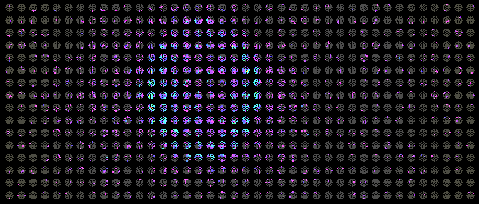
II.2.6.4.3.2 The mPMT Prototype
The design of a KM3NeT mPMT module is restricted by the size of commercially available transparent pressure vessels: borosilicate glass spheres with a diameter of 33.3 cm and 43.5 cm. The glass sphere also contains radioactive contaminants that emit Rn into the water, which is not a problem for KM3NeT where the radioactive background rate is limited by 40K in the sea water. Pure glass could be used for the vessel in Hyper-K, but the cost should increase, therefore a good alternative is given by acrylics. A first prototype of an mPMT of the future Hyper-K experiment is under construction mainly to demonstrate the effectiveness of a vessel system based on acrylic and to study a better solution for the PMT Read-out system. Other prototypes will be built and tested when the final design of the mPMT will be defined on the basis of the optimization studies. Several comparative tests are ongoing to identify the best acrylic for the experimental requirements, including optical tests, stress and compression mechanical tests and thermal tests. The water absorption tests are based on Nuclear Reaction Analysis (NRA), whereas radioactivity contamination measurements are based on gamma spectroscopy. The UV transparency has been measured for several commercial acrylics. For some sample, the light transmittance of the acrylic cover measured in water is greater than 95% for a wavelength longer than 350 nm. The pressure vessel will be realized starting from two acrylic hemispheres. The hemisphere fabrication processes starts by blowing the flat sheet onto a positive mold. A mold made from two parts (i.e., positive and negative) could be used to have a more uniform thickness. The final design of the vessel will be defined on the basis of the simulation studies for the mPMT optimization.
For the pressure vessel closure system, the two acrylic hemispheres might be glued by using a specific glue for acrylics. However, glue itself could emit light, producing more background events for low-energy physics. A mechanical system has been evaluated, both to avoid fluorescence emissions, and to guarantee a longer endurance, and to simplify the anchorage to the tank frame and the implementation of the cooling system of the mPMT. Thus a metallic ring is being evaluated, modifying the spherical final shape by extending the equatorial zone with a cylinder. The acrylic vessel in the mPMT is similar in price to the protective cover required for the single large PMTs.
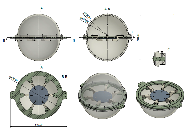
The first mPMT prototype will have an acrylic vessel with a diameter of 17 inches (432 mm, as in KM3NeT). Several commercial acrylics have been studied and tested. EVONIK UV transmitting PLEXIGLAS GS 444http://www.plexiglas.net has been chosen for the construction of the first prototype. The thickness of the vessel has been studied on the basis of simulation and three vessel prototype with thickness of 12, 15 and 18 mm will undergo to preliminary pressure tests. The sphere will house 26 PMTs with a photocathode diameter of 7.7 cm.
19 PMTs will view the inner detector side and 7 PMTs will view the outer detector side. The final number of PMTs in the mPMT will be defined on the basis of simulation studies. The PMTs will be placed into a 3D printed structure and will be optically and mechanically coupled by Silicon Gel to an acrylic pressure sphere. The optical gel used for this prototype will be the same as in KM3NeT. The compatibility between optical gel and acrylic has been checked and the transparency of acrylic+optical gel has been measured. For the final mPMT design, other options for the optical gel are under study.
For the present prototype module, Hamamatsu R12199 PMTs are used. They are arranged in 3 rings of PMTs in the hemisphere looking at the inner detector with zenith angles of 33∘, 56∘, 72∘, respectively. In each ring 6 PMTs are spaced at 60∘ in azimuth and successive rings are staggered by 30∘. The central PMT in the hemisphere point at a zenith angle of 0∘, looking at the inner detector axis. Seven PMTs are arranged in the hemisphere looking at the outer detector. Six of them are arranged in one ring which opens a half angle of 33∘ with respect to the nadir.
A basic Cockcroft-Walton voltage multiplier circuit design developed by KM3NeT Collaboration Timmer et al. (2010) is used to generate multiple voltages to drive the dynodes of the photomultiplier tube. The system draws less than 1.5 mA of supply current at a voltage of 3.3 V with outputs up to -1400 Vdc cathode voltage. A passive cooling system, based on the heat conduction mechanism, aimed at keeping the temperature of the electronic components as low as possible, thus maximizing their lifetime has been designed in order to optimize the transfer of the heat generated by the electronics. In KM3NeT the time over threshold (ToT) strategy is exploited; this is not a good solution for Hyper-K project in which charge measurement is important. To fulfill the requirements of low consumption and charge and time resolution, a solution based on a Sample&Hold plus ADC has been investigated. Several commercial low power and highly versatile ASIC from Weeroc 555http://www.weeroc.com are under study.
For this prototype, the module was developed as a complete stand-alone detector and it will fully test both in air and in water.
II.2.6.4.4 Alternative Cover Design
An alternative design of the shockwave prevention cover is a cheap stainless steel tube with the acrylic window, instead of the conical shape cover, as shown in Figure 91. Benefit of the mass production and installation is expected due to the simple outer shape.
Figure 91 shows another possible idea to use a resin instead of stainless steel. It can give a cheap and light weight option. One of the possible material is PPS resin mixed with a reinforced filler.
![[Uncaptioned image]](/html/1805.04163/assets/x101.png)
![[Uncaptioned image]](/html/1805.04163/assets/x102.png)
|
The light weight of the cover allows for a lower cost of the tank structure because the current cover weight is much heavier than the PMT and dominant in overall weight of the photosensor system. Fast production and installation are also cost effective. In both alternative cases, the design was evaluated by a simulation assuming a high pressure load outside, but it is still preliminary. The hydrostatic test and demonstration test with implosion are necessary to ensure that the alternative covers are feasible for Hyper-K.
II.2.6.5 Schedule
Before the photosensor mass production, it takes 0.5 years to complete a design of a production line, and 1–1.5 years for the setup and startup of the equipment in the factory. The capacity of the factory production is expected to be 11k 50 cm and 4k 20 cm photosensors per year.
A test in Super-K using about a hundred of the B&L PMTs starts from 2018 to demonstrate the Hyper-K photosensor system. Moreover, criteria for the quality control including a selection with high pressure load will be established by the production.
Table 20 summarizes the default design and alternatives for photosensors described in this section. Even without the alternatives, Hyper-K has sufficient performance with a realistic time line using the default options. Further improvements could be achieved and could be available in time for Hyper-K tank construction.
| Items | Type | Remaining studies | ||
|---|---|---|---|---|
| ID photosensor |
HQE 50 cm
B&L PMT (Hamamatsu R12860-HQE) |
![[Uncaptioned image]](/html/1805.04163/assets/x103.png)
|
Mass test using about 100 PMTs with reduced dark hit rate | |
| (Alternative) | HQE 50 cm HPD (Hamamatsu R12850-HQE) |
![[Uncaptioned image]](/html/1805.04163/assets/x104.png)
|
Electronics tuning, Confirmation of pressure resistance, Long-term proof test in water, Cost estimation | |
| OD photosensor |
HQE 20 cm
B&L PMT (Hamamatsu R5912) |
![[Uncaptioned image]](/html/1805.04163/assets/design-photosensor/figures/photosensor_8pmtassy2.png)
|
Test in high pressure water | |
| (Alternative) | HQE 20–30 cm PMT | HQE study using prototype, | ||
| Trial manufacture and necessary test | ||||
| (Alternative) | 7.7 cm PMT |
![[Uncaptioned image]](/html/1805.04163/assets/design-photosensor/figures/3inchPMT.jpg)
|
Performance simulation in Hyper-K, Detection efficiency measured with prototype, Selection between design | |
|
(ID and OD
photosensor alternative) |
Multi-PMT optical module |
![[Uncaptioned image]](/html/1805.04163/assets/design-photosensor/figures/mPMT_NuPRISM.png)
|
Performance simulation in Hyper-K, Cost estimation, Selection of 7.7 cm photosensor, Trial manufacture and necessary test | |
| ID cover |
Acrylic and
stainless steel cone |
![[Uncaptioned image]](/html/1805.04163/assets/x105.png)
|
Improved with light weight, Test of the improved design | |
| (Alternative) | Acrylic and stainless steel tube |
![[Uncaptioned image]](/html/1805.04163/assets/x106.png)
|
Design and simulation, Implosion test | |
| (Alternative) | Acrylic and full resin |
![[Uncaptioned image]](/html/1805.04163/assets/x107.png)
|
Design and simulation, Prototype production, Implosion test | |
II.2.7 Frontend electronics
II.2.7.1 General concept of the baseline design
It is not possible to tell when and where a natural neutrino interacts in the detector. Therefore, the front-end electronics modules for the detectors, which are used to study neutrino from nature, are required to digitize all signals from photo-sensors that are above a certain threshold – i.e. the acquisition needs to be self-triggered. The digitized information is then either recorded or discarded, depending on the design of the detector-wide trigger system.
Current design of the HK detector is quite similar to the SK detector, in terms of the required specifications and the number of photo-sensors in one detector. Therefore, it is reasonable to start with the system used in the SK detector.
The photo-sensor for the inner detector of HK is newly developed. Based on the baseline option, around 40,000 20inch PMT R12860-HQE is used. The R12860-HQE PMT has better timing and charge resolution compared to the same diameter PMT (R3600), which has been used in SK. The dark (noise) rate is required not to exceed 4 kHz, which is a similar requirement to the R3600 PMT. Based on these information, we have estimated the total data rate and concluded that it is possible to design the data acquisition system, which has similar to the concept of the SK-IV DAQ.
As already realized in the SK-IV DAQ system, it is possible to read out all the hit information from the photo-sensors, including the dark noise hits. There is no technical problem in selecting the actual events to be recorded for the analyses by software.
One difference is the size of the detector. The total amount of photo-sensors in one entire detector is expected to be up to 47,000, including the sensors for OD. If we locate the front-end electronics modules on the top of the detector, it is necessary to run the cable from the PMT to the roof and the detector structure has to support the weight of the cables, which is expected to be 800 tons. Thus, it would be possible to simplify the detector structure if we can reduce the weight of the cables. Also, the maximum length of the cable is 30% longer than in the SK case. This not only reduces the signal amplitude, but also degrades the quality of the signal – the leading edge is smoothed out due to higher attenuation of the cable in the high frequency region. Therefore, we plan to place the modules with the front-end electronics and power supplies for the photo-sensors in the water, close to the photo-sensors. This configuration makes it possible to have shorter signal cables from the photo-sensors and also allows for significant reduction of the weight that needs to be supported by the photo-sensor support structure. Of course, it is necessary to place the front-end module and power supply for the photo-sensors in a pressure tolerant enclosure, and also to use water-tight connectors. This kind of “water-tight” casing has been studied in other experiments and there are several possible options. One concern is the cost of the special cables and connectors – consequently, we are developing special cables and connectors dedicated for HK.
The other issue we have to keep in mind is an inability to do any repairs to a broken module that will be submerged in water. Furthermore, a failure of one module could affect the data transmission from other modules, resulting in a much larger region of the detector that could be lost. Therefore, the system must be redundant and care must be taken to avoid a single point of failure. Also, careful design of the data transport connections and the timing distribution system are essential.
The current baseline design of the front-end module is prepared considering these requirements. The schematic diagram of the front-end module is shown in Fig. 92.

There are 4 main function blocks in the front-end board. The signal digitization block, the photo-sensor power supply block, the slow control block and the communication block. In the current baseline design, one module accepts signals from 24 photo-sensors, digitizes them and sends out the data.
In the following sections, details of each component of the front-end module are described, along with the data readout and processing parts.
II.2.7.2 Signal digitization block
The signal digitization block accepts the signals from the photo-sensors and converts them to the digital timing and charge data. As mentioned in the previous section, there is no way to tell when a neutrino or a nucleon decay event happens. Therefore, the front-end electronics module is required to have self-triggered analog to digital conversion mechanism and to be dead-time free. The actual event rate is expected to be smaller than a tens of kHz, even with the background events from gamma-rays from the surrounding wall or from cosmic-rays. Also, the number of photo-sensors, which detect sufficient charge in case of gamma-ray events is quite small, much less than 1% of the photo-sensors in the detector. Therefore, the time interval between photons hitting a single photo-sensor is rather long, much longer than the dark rate of the sensor. However, muons decay into electrons in the detector and photons from both of them may hit a single photo-sensor. Therefore, it is necessary to have the capability to detect both photons, generated by the parent muons and the decay electrons. The lifetime of muons are rather long, 2 sec and thus, it it not necessary to be completely dead-time free but the dead-time should be as short as possible.
One possible way to satisfy these requirements is to employ the charge-to-time conversion (QTC) chips. The QTC chip receives the signal from the photo-sensor and produces the digital signal, whose width is linearly dependent on the amount of the input charge. Also, the leading edge of the output digital signal corresponds to the time when the input signal exceeded the pre-defined threshold to produce the output digital signal. The digital output signal from the QTC chip is read out by a TDC. Usually, the maximum width of the output signal may be slightly longer than the charge integration gate width. Therefore, there is a small dead-time after the first signal but it is no larger than several hundreds of ns and is acceptable for use in the water Cherenkov detector.
The requirements of the charge and timing resolution are summarized in Table 21.
| items | required values |
|---|---|
| Built-in discriminator threshold | 1/4 p.e ( 0.3 mV ) |
| Processing speed | 1sec. / hit |
| Charge resolution | 0.05 p.e. ( RMS ) for 5 p.e. |
| Charge dynamic range | 0.2 2500 pC ( 0.1 1250 pe. ) |
| Timing response | 0.3 ns RMS ( 1 p.e. ) |
| 0.3 ns RMS ( 5 p.e. ) | |
| Least time count | 0.52 ns |
| Time resolution | 0.25 ns |
| Dynamic range | 15 bits |
The QTC chips ( CLC101 ) used in the front-end module of SK-IV, called the QBEE, are a good reference and satisfy all the requirements. The design rule of these chips is 0.35m and it is possible to produce them again. As for the TDC, the chips used in the QBEE, called AMT3, have been discontinued. However, there are several implementations of a ‘TDC in an FPGA’ and some of them seem to have sufficient performance. One candidate is the ‘wave union TDC’ developed at FNAL. The performance of this TDC is expected to be better than that of the AMT3 and we are currently evaluating this TDC design.
Even though the current baseline design is to utilize the QTC-TDC approach, we are also investigating possibility of adopting Flash-ADC (FADC) type digitization. In this case, the FADC chip would run all the time and digitize the input signal. Afterwards, FPGA-based on-the-fly digital signal processing would be utilized to find the PMT pulse and determine its charge and time of arrival. An advantage of this approach is that it is completely dead-time free – we would be able to detect photons both from prompt muons and from decay electrons, even if the latter happen only 100 ns after the initial interaction. We may also be able to distinguish photons from direct and reflected light. Another potential advantage is an ability to remove deterministic interference that may be present in the PMT signal. Example sources of such an interference are switching power supplies and high voltage supplies. The disadvantage is potentially larger power consumption and higher cost.
Since both the power consumption and the cost are highly dependent on the speed and precision of the FADC ICs, it is advisable is to use the slowest possible configuration that will ‘do the job’. As such, a study has been performed in order to understand the performance of the system as a function of both the resolution and the sampling frequency of the FADC. Furthermore, models of the system were developed and validated, so that further studies can be streamlined. Finally, various signal processing methods were tested for determining timing of the pulse – among them the digital constant fraction discriminator Huber et al. (2011), optimal filters Gatti et al. (2004); Abbiati et al. (2006) and matched filters. The results of the study are presented in Fig. 93. It is relatively easy to achieve the timing resolution that is below 10% of the sampling period (). With sufficiently high SNR it is also possible to reach even better timing accuracy, well below 1% of . Based on these results, we decided to use a 100 MSPS/14 bit FADC as the current baseline design for this digitization scheme. Two FADC channels will be used per single PMT (high-gain and low-gain channels), so that the dynamic range requirements are fulfilled. Current studies concentrate on optimizing an anti-aliasing filter, in order to achieve best possible timing resolution.


Another solution, which allows for savings in power consumption and still maintains high sampling frequency, is to use switched capacitor arrays (SCA). The biggest advantage of this approach is that no bandwidth-limiting anti-aliasing filter is necessary. The price to pay is dead-time introduced due to ‘freezing’ of the capacitor, which is necessary for its readout. One possibility of alleviating this problem is to utilize multiple SCA channels per photo-sensor. This way a dead-time free readout can be provided up to a certain trigger frequency. A better option is to use SCAs with segmented memory, so that one can avoid potentially expensive increase of the number of SCA chips. Unfortunately, we are currently not aware of an existence of such an IC, with sufficiently large memory buffer. Therefore, we are considering possibility of a development of a new IC. The goal would be to allow both a dead-time less readout, typical for pure FADC-type digitization, as well as high sampling speeds and low power consumption, provided by the SCAs.
The basic assumption of the new design is that the chip would consist of both an SCA-type analog memory, a flash-ADC and a discriminator. The sampling speed of both the SCA and the flash-ADC would be equal. The flash-ADC, which is the most ‘power hungry’ part, would be kept off most of the time – it would be activated only once a sufficiently high pulse is detected at the input. Since some time is required for resuming the flash-ADC operation, the analog memory would be used to store the pulse – sampled, but not yet quantized. Once the ADC is fully active, the analog memory would act as a first-in first-out buffer, without any freezing of its content. Thus, the system would be able to work as long as there is any useful signal, without any dead-time.
In either case, it is necessary to be prepared for a failure of the digitization component. We are therefore considering to have a set of spare digitizer channels and to insert analog switches between the signal inputs and the digitization block. With this configuration, we have some flexibility to change the assignment of input signals to digitizer channels. This also provides us with an additional way to calibrate the digitization blocks. Of course, analog switch is known to degrade the quality of the signal. Thus, we are going to study carefully prior to implementing this solution. Furthermore, the photo-sensors, which are currently considered, produce faster pulses and, consequently, higher maximum voltage, which is expected to exceed 6 volts. This is larger than the maximum allowable voltage of the digitizer chips. Therefore, we need to design the protection circuit, which will not degrade the timing and charge resolutions.
Because the relative timing is used to reconstruct the event vertex in the detector, all the modules have to be synchronized. Therefore, it is necessary to drive the TDC or FADC by a clock synchronized to the reference clock fed externally. Also, the system-wide counter is attached to the data to combine the data from different modules at a later stage.
II.2.7.3 The timing synchronization block
Synchronization of the timing of each TDC or FADC is crucial for precise measurement of the timing of photon arrival. In Hyper-Kamiokande, timing resolution of the photo-sensor is expected to be largely improved. Therefore, we have to be careful with the synchronization of the modules – the design should minimize the clock jitter, so that the timing resolution of the whole system is as good as possible. We are planning to distribute the common system clock and the reference counter to all the modules. We have not yet started the actual design of this system, but there are several existing examples. The first method is to send the clock and serialized 32 bit counter information using special STP cable, called the nano-skew cable, whose skew is less than a few nanoseconds for a 100 m long cable. This system has been used in current SK DAQ system and the skew is measured to be much smaller than 100 ps. It requires intermediate timing distributor and therefore needs to be modified for use in Hyper-Kamiokande, but it is not difficult. The other possibility is to use the idea of White Rabbit. The White Rabbit system is designed for the synchronization in the accelerator complex and corrects the timing differences with measured delay in each node. It is not necessary to implement entire functionality of White Rabbit for our case but employ the main part of the timing synchronization and stabilization.
II.2.7.4 The photo-sensor power supply block
If HPDs are used as the photo-sensor, the high voltage supplies for the acceleration voltage and the avalanche photodiode bias voltage will be put on the HPD base. In this case, the front-end module will control both power supplies via control signals.
If the normal PMTs are used as the photo-sensors, we are considering to put the high voltage module in the same enclosure as the front-end module. In this case, the control signal would be fed internally between the two modules.
The control signals to the HPD base or to the internal high voltage modules will be controlled remotely through the communication block.
II.2.7.5 The slow control and monitor block
It is important to control and monitor the status of the power supply for the photo-sensors. Also, the voltage, the current and the temperature of the front-end module has to be monitored. This slow control and monitor block is prepared for this purpose. It accepts the commands from the communication block and also keeps the current status, which is available for read-back. All communication with the ‘external world’ is done through the communication block.
II.2.7.6 The communication block
In order to reduce the amount of cables, we are planning to connect the modules in a mesh topology, with each module connected to its neighbors – Fig. 94. Only the top modules would be connected to the readout computers. Each module will have several communication ports, so that a single point of failure would be avoided. In case of failure of one of the modules, the data would simply be re-routed to one of the neighbors, thus ensuring that communication path will be secured.

There are several possibilities for the connection, but one of the promising ones is the SiTCP, an FPGA based TCP/IP stack. This TCP/IP stack does not require a CPU core in the FPGA and is accessible like a simple FIFO buffer. SiTCP acts as either a TCP/IP server or a client, so it is possible both to receive data from the other module and to add own data and later to send everything to the next module. Also, SiTCP has registers, which can be accessed via UDP commands. With this functionality, it is possible to realize the slow control and monitor system, such as setting the high voltage or monitoring the status, for example read-back of voltages of the power supply. Recently, CPU cores are embedded in the FPGA chip. With this kind of chips, TCP/IP communication part is also possible to be handled with the embedded CPU. We will investigate this possibility. Apart from TCP/IP, there are several other industry standard communication protocols available. One example is the Rocket-I/O. Rocket I/O is the standard interface supported in Xilinx FPGA. This allows us to transfer data at speeds exceeding gigabit per second. We are also investigating this possibility for a faster communication between the modules.
II.2.7.7 Pressure tolerant cable and Water tight connectors
In order to connect the front-end electronics module with other modules, the photo-sensors and the clock modules, we need to have water tight connectors and pressure tolerant cables. It is known that normal Ethernet cables are not capable of transmitting the data at full rate under the pressure, because the characteristics of the cable are changed when the cable is squeezed under the pressure. Therefore, we have started the R&D of the pressure-tolerant, water tight Ethernet cable. This cable will use the similar sheath material to the one used as the photo-sensor signal cable not to affect the water quality of the detector. We have also started designing the water tight connectors for the PMT connection and the Ethernet connection. Both of the connectors are using screws and are easy to connect. This will reduce the time to connect cables during the construction. The mock-up connectors have been designed and we are going to produce samples and evaluate them in the coming years.
II.2.7.8 Timeline
Current plan from the finalization of the design to the completion of the production and tests is shown in Table 22
| Spring 2020 | Final design review of the system |
| Autumn 2020 | Start the design of the system based on the design review |
| Autumn 2021 | Start bidding procedure |
| Autumn 2022 | Start mass production |
| Autumn 2023 | Start final system test |
| Autumn 2024 | Complete mass production |
| Autumn 2025 | Complete system test and get ready for install |
In order to complete the design by Spring 2020, R&D and evaluation of each component have to be finished by then. Table 23 shows the deadlines for each component.
| Digitizer | Autumn 2018 based on the decision of the photo sensors |
| Timing and synchronization | Select technology by Autumn 2018 |
| Communication block | Fix specification by Autumn 2018 |
| Design by Spring 2019 | |
| High voltage system | Product selection and design by Autumn 2019 |
| Water tight components | Technology choice by Spring 2019 |
Considering the schedule, we need good coordination with the other groups, including not only the photo-sensor groups but also the construction groups. The allocated time for each item is not much but still achievable.
II.2.8 Data acquisition system
II.2.8.1 Data acquisition and triggering
All PMT hits from the detector (above a threshold of p.e.) will be delivered to the data readout and processing system where they will be formed into events and recorded on disk for further processing offline. The overall rate of hits (mostly from dark noise) from the inner detector will be about 460 MHz, leading to a total input data rate of 5GB/s including additional data, in the absense of waveform information. The OD adds less than 10% to this data load. To reduce the data recorded, trigger decisions will be made using real-time processing of the hits in the detector. Events will be formed from all hits within a time-window surrounding the trigger and recorded to disk for offline study.
The main trigger will be the same as that used in SK-IV; a trigger will be generated when the total number of hits seen (NHITS) in a sliding time-window exceeds a certain threshold (e.g. 27 hits). This trigger will accept all the necessary data for studies of proton decay, atmospheric neutrinos, beam neutrinos and cosmic ray muon events. It is important that there is no dead time in the triggering or data collection so that delayed energy depositions following a triggered event, such as from a Michel electron or neutron capture, are recorded, either as part of the same event or separately. More sophisticated trigger algorithms, which can be added into the architecture, are being studied to increase sensitivity to lower energy events (by distinguishing events with fewer hits from random combinations of dark-noise hits) and detection of supernova bursts (by observing elevated trigger rates). As in Super-K, an additional trigger input will be derived from the J-PARC beam-spill gate to define readout windows around the beam spill time, independent of the number of hits observed. Triggers will be defined to receive calibration events. Also, external trigger inputs are necessary to take the calibration data with synchronized timing. The estimated rate of events is shown in Table 24 for readout with the hit-only electronics, which require 12 bytes per hit (the waveform option needs a factor four higher bandwidth, bytes of information per hit).
| Data source | Event rate | Hits/event | Data rate | Data rate | Data rate per |
|---|---|---|---|---|---|
| (event window) | pre-trigger(a) | pre-trigger(b) | event window | ||
| Dark noise | 10 kHz each in 46,700 PMT | 1 | 5.6 GB/s | – | – |
| Very low energy background | 10 kHz (1.5 s) | 25 | 3 MB/s | 84 MB/s | 200 MB/s |
| Low energy background | 35 Hz (40 s) | 50 | 21 kB/s | 7.8 MB/s | 15 MB/s |
| Cosmic muons | 100 Hz (40 s) | 46,700 | 56 MB/s | 78 MB/s | 15 GB/s |
| Beam events | 1 Hz (1 ms) | 0 | 0 MB/s | 5.6 MB/s | 5.6 kB |
| Calibration | 2 Hz | 46,700 | 2 MB/s | 2 MB/s | – |
| Pedestal | 1 Hz | 46,700 | 2 MB/s | 2MB/s | – |
| Total rate | 5.6GB/s | 180MB/s |
A requirement of the data acquisition system is to reliably trigger and collect information from a supernova burst. This is one of the more challenging design aspects and benefits from the large memory buffers available in modern commodity hardware, sufficient to retain all raw hit information for around 100 s of detector operation. In the event of a supernova, the detector will self-trigger on a supernova burst by searching for an elevated rate of individual triggers in a sliding time-window e.g. 0.1 s. If such a trigger occurs, all raw hit information in a large time window around the supernova trigger would be saved in the local hardware and then slowly written to disk. Note that even a close supernova burst yielding 100,000 events per second of 50 PMT hits each (5 million hits/s) will not overwhelm the readout which is designed to continuously read 460 MHz of dark noise hits. A large storage buffer on hard disk drives is used to save all the hit data, overwriting the oldest data. An external observation may reveal up to a few hours after the event that a supernova signature was seen, perhaps in a neighbouring galaxy, in which only a few events are expected to be observed in Hyper-K.

Figure 95 is a schematic diagram of the data readout and processing system showing the five steps in the sequence of readout operations. The main components are readout buffer units (RBU) that receive PMT hit (and possibly waveform) data from the front-end boards, trigger processing units (TPU) and event building units (EBU). The sequence of operation is indicated by the numbers 1-5 on Figure 95: (1) Data on hits in a group of channels are streamed into buffers in the RBUs, where they are retained for the duration of the trigger decision. (2) A summary block of information for triggering is sent to the TPUs. (3) Trigger decisions are delivered back to the RBUs to extract event data from the buffer. (4) The event data are sent to the EBUs. (5) Built events are written to disk for later processing offline. A description of each of the blocks shown is given in the following sections. The DAQ system will be designed to be homogeneous, flexible and scalable.
Parameters of the readout system, including data rates at each point in the sequence of readout operation are shown in Table 25. Since the architecture is flexible, the additional data generated by the waveform option is easily accommodated, although a larger number of Readout buffer units (RBUs) would be required.
| Parameter | Hit-only option | Waveform option |
|---|---|---|
| Pre-trigger input data rate | 5,600 MB/s | 23,400 MB/s |
| Number of RBUs | 38 | 122 |
| Input rate to each RBU | 150 MB/s | 188 MB/s |
| Latency provided by RBU (pre-trigger buffer length) | 109 s | 87 s |
| Trigger info output rate per RBU | 50 MB/s | 15 MB/s |
| TPU data input rate (for 16 TPUs in detector) | 117 MB/s | 117 MB/s |
II.2.8.2 Readout buffer unit (RBUs)
The RBUs receive continuous streams of data from the front-end cards and perform three main tasks. First they store incoming data in buffer storage. A short-term store of the most recent data is retained whilst trigger decisions are made and a long-term storage area is reserved in case of a supernova event until it can be read out. Second, it forms a compressed block of data which is handed to the TPU for trigger decision making. Finally, the RBU handles trigger requests to dispatch complete event data to the event builder unit, and supernova trigger requests to move data to the long term storage area. Since the detector is large, and to allow scalability, there are many RBUs working in parallel, each responsible for processing data from a designated region of the detector. In the current design of 45,000 PMTs, between about 40 and 120 RBUs will be required depending on the amount of data received per hit, and each will use 16 GB of memory to provide the necessary storage. The RBU design is scalable and thus largely independent of the detector size.
The final design of the RBUs depends on the layout and interface of the upstream electronics. Possible implementations use either commodity computers with commodity network switches to direct the data, or hardware receiver cards in a communication-crate such as Advanced Telecommunications Computing Architecture (ATCA) with a commodity computer as a controller. The RBU may also include an interface to the upstream link for monitoring information.
II.2.8.3 Trigger processing unit
The Trigger Processing Units (TPUs) will accept compressed trigger data blocks from the RBUs and use these to form trigger decisions, such as the simple, robust NHITS trigger. Hooks will be provided to allow for more sophisticated triggering. The trigger will also search for large collections of individual events, which may indicate a burst of neutrinos from a supernova explosion in the galaxy.
The trigger will operate using windows of fixed time duration (e.g. 60 per second) in order to allow the trigger processing to be parallelized. The parallelisation allows for a scalable design that can be extended easily if workloads change due to increased darknoise, as well as handling any reprocessing due to errors or data corruption. One TPU is allocated for a given time window and will process all the data in that time window. The TPUs are connected to the RBUs by a switched Ethernet network to allow the data from the different RBUs (one for each section of the detector) to be routed to the correct TPU. The data is transferred asynchronously and the TPU starts processing when all data packets have arrived.
The trigger information can be compressed into a 32-bit word per hit to identify the channel number within the RBU (10 bits) and the time within the window (21 bits) to 10 ns accuracy (better time resolution is not needed in the trigger) and one spare status bit. The trigger information can be truncated if it is clear that the NHITS trigger will be satisfied from the data in that one RBU alone, as in this case, the event is guaranteed to be collected without further transfer or processing of trigger data. For this level of packing, the output rate per RBU will be about 30 MB/s and if a farm of 16 TPUs is used, the input rate to each will be around 100 MB/s. The final design of the TPUs is largely independent of the choice of front-end electronics, because the RBUs provide the trigger data in the same format regardless. The TPU design depends on the type of processing required for the sophisticated triggers. The base line design is to use commodity computer componets, where data packets would be received by the computer and complex trigger processing would occur in FPGAs or GPUs that read the data over PCIe links and deliver the trigger verdict for a given time block back to the main memory.
II.2.8.4 Event Building Unit
Once the trigger decision has been made for a time-window, the decision is reported back to a central trigger control process, from where it is delivered to the RBUs. The request contains an event number, and the definition of the position and width of the trigger window. The central trigger control process also looks for an increased rate of positive triggers, which would be indicative of a supernova burst, and in such case sends the RBUs an instruction to save the relevant data in the long-term part of the buffer memory.
On receipt of a normal trigger, the RBUs send all the hits in the trigger window to a designated event-building node, which puts the event together and writes it to the output file. Once the file reaches a certain size, it is closed and released for offline processing, and new events are recorded in a new output file without interruption. The event builders also allow events to be read by monitoring and event display programs. Once a supernova trigger has occurred, a separate event-building stream is used to gather the data in the long-term part of the RBU memory and output it to a separate file. There will be one file per supernova trigger. A straightforward implementation of the event builders is to use commodity computers.
II.2.8.5 Triggering
A trigger will be issued if any event exceeds a pre-determined threshold of hits (NHITS) in a sliding time window. This trigger will accept with high efficiency, all events for studies of proton decay, atmospheric neutrinos, beam neutrinos and cosmic ray interactions. Aside from the NHITS requirement, the trigger must have no dead time as this could lead to the loss of information from associated delayed energy deposition events such as Michel electrons or neutron captures.
The low energy threshold limited by the dark noise rate of the PMTs, which prevents the use of such a simple NHITs trigger for low energy physics events such as solar neutrinos, supernova and neutron capture. To allow sensitivity to low energy physics, the Hyper-K DAQ system must incorporate intelligent, fast trigger algorithms that can reject noise events but retain the low energy physics events of interest. Any event that fails the NHITS threshold will be passed to the low energy trigger.
The base line low energy trigger design uses a grid of test vertex positions with 5 m spacing inside the detector. The distance between each test-vertex and PMT position is used to produce a look up table of time of flight information for each test-vertex PMT pair. For an event, the ID and TDC information for each tube are recorded and passed to the test-vertices algortihm. The algorithm loops over the test-vertices and corrects the measured TDC by the time of flight for each test-vertex PMT pair. This corrected value represents the time at which the photon was emitted by the test vertex to produce the observed PMT hit. A one dimensional histogram of photon emission times is produced with a carefully chosen bin width corresponding to half of the time resolution. The best vertex is found by selecting the histogram bin with the highest number of entries and if this number of entries is greater than a pre-determined threshold, the trigger is accepted. Due to the computational intensity of this process, it will be executed using high performance Graphical Processing Units (GPUs). Results from Monte Carlo simulations show high noise rejection and good low energy acceptance.
A second trigger that uses convolution neural nets and GPUs to perform real-time image recognition for triggering is also being investigated. Initial studies have proven very promising, with good performance even at very low energies. Other specialist triggers will be developed for calibration sources and supernova detection.
Adaptations will be made to trigger algorithms for the use in the intermediate detector. As the low energy physics reach of the intermediate detector is less than that of the far detector, the triggering scheme can be simplified. However, low energy triggers will be required to accept gadolinium gamma cascades. Work in this area is continuing.
II.2.9 Detector calibrations
The Hyper-K detector consists of an Inner Detector and an Outer Detector and both detectors need to be calibrated. The Super-K detector has been successfully operated for about two decades and established several techniques to calibrate a large water Cherenkov detector Abe et al. (2014f). Hyper-K calibrations are designed based on and extension of the Super-K calibrations. This section describes the calibration strategy and methods for Hyper-K detector.
II.2.9.1 Inner Detector Calibration
Hyper-K detector calibrations consist of two major phases: calibrations of the detector system, e.g. PMTs, and calibrations dedicated for physics analyses. The calibrations for the detector system is to characterize the PMT responses, including readout electronics, and the optical properties of detector material, e.g. water, PMT (glass bulb and housing material), black sheet, and tyvek sheet. The calibrations for physics analyses are designed to satisfy the requirements from Hyper-K physics program which consists of variety of physics topics covering wide range of energy region, from a few MeV to several hundred GeV. For these calibrations, various calibration techniques have been developed and established by Super-K and they are applicable to Hyper-K calibrations without major technical difficulties.
Table 26 summarizes the calibration items and the calibration sources used in Super-K calibrations for reference. These calibration items are important to characterize the Hyper-K detector responses, and the calibration results need to be implemented in the detector simulation.
| Calibration items | Calibration sources used in SK |
|---|---|
| Photosensor & electronics calibrations | |
| High-voltage tuning | Xe flash lamp |
| Single photo-electron charge (gain) | Nickel source |
| Electronics threshold effect | Nickel source |
| Photo-detection efficiency | Nickel source |
| Non-linearity (photosensor and electronics) | Nitrogen-dye laser |
| ‘Time-walk’ correction (TQ map) | Nitrogen-dye laser |
| Timing resolution | Nitrogen-dye laser |
| Dark noise | Off-timing hits |
| Optical properties of detector material | |
| Light transparency of water (absorption, scattering) | Nitrogen laser, laser diodes, Xe flash lamp |
| Optical properties of PMT glass & housing material | Nitrogen laser, laser diodes, Xe flash lamp |
| Calibrations dedicated for physics analyses | |
| Solar and supernova etc.: energy scale and vertex | LINAC, DT generator, Nickel source |
| Beam and atmospheric etc.: energy/momentum scale | Cosmic-ray muons, decay-e’s, etc. |
As shown in the Table 26, the detector calibrations require various calibration sources: light sources, radioactive sources and physics events such as cosmic rays. Note that “Nickel source” listed in Table 26 is a calibration source to generate single photo-electron (p.e.) level of light, which isotropically emits 9 MeV gamma rays from thermal neutron capture on nickel with the reaction of 58Ni()59Ni, where 252Cf is used as a neutron source. With the use of a Nickel source, for example, “relative” photo-detection efficiency, (quantum efficiency times collection efficiency) of each single PMT is calibrated by evaluating relative differences of the hit rates between PMTs for single photon level of light. The “low-energy physics” events like solar neutrinos mostly consist of 1 p.e. hits and thus the relative photo-detection efficiency calibration plays an important role for the low energy physics analyses. On the other hand, PMT/electronics linearity calibration for the full dynamic range is important for “high-energy physics” events like atmospheric neutrinos, which can involve 100 GeV-scale muons. For the linearity calibration, a nitrogen-dye laser is used in Super-K, which is utilized with a variable light attenuation filtering system to obtain a variety of light intensities covering the full dynamic range of PMT and readout electronics (0.25 p.e. to 1000’s p.e.). In addition to calibrations of the PMTs and electronics, understanding of the optical properties of the water plays a key role in all physics analyses of Super-K and Hyper-K. The water optical properties, absorption and scattering of light, are calibrated as a function of time and position in the detector volume using a series of laser diodes with various wavelengths. Since the detector condition can change from time to time, the continuous monitoring and periodical calibrations of these detector components are also indispensable over the lifetime of the experiment. There are many other calibrations to characterize/monitoring the detector system, as explained in Ref. Abe et al. (2014f) for further details.
The Hyper-K physics program consist of various physics topics which cover a wide range of energy from a few MeV to several hundred GeV. For example, low energy events like solar neutrinos and supernova neutrinos are in a few MeV up to tens of MeV, neutrinos from the J-PARC beam and nucleon decay events are around 1 GeV, and atmospheric neutrinos are in a range between 1 GeV and several hundred GeV. For physics analyses in each energy regime, there are a series of dedicated calibrations, e.g. energy scale, which are described in the later sections.
For all necessary detector calibrations in Hyper-K, the calibration methods and techniques established in Super-K are sufficiently good enough, and we do not see any technical difficulty to apply them to Hyper-K. We have, however, been developing more sophisticated calibration sources/systems for Hyper-K in order to minimize the detector downtime and manpower required for the detector calibrations since Hyper-K detector has a larger detector volume than Super-K. The following sections discuss the status of research and development for Hyper-K calibrations.
II.2.9.1.1 Detector Calibration Systems
In order to achieve the level of calibration required for the Hyper-K physics program we require an extensive calibration infrastructure. Data from in situ sources such as cosmic muons or Michel electrons will be used to supplement the information from these systems, but they cannot replace them. In Hyper-K we propose two systems, a source deployment system to allow the deployment of calibration sources across the detector inner region and an integrated light injection system for the inner and outer detector regions. These two calibration systems provide the data that will be required to characterise the detector and reduce the systematic uncertainties to the required level. The integrated calibration system allows for calibration and monitoring of the detector without the deployment of specialised manpower while calibration sources can be used for more extensive calibrations during the time when the neutrino beam is off.
II.2.9.1.1.1 Calibration sources and deployment system
Similar to other water Cherenkov detectors the ability to deploy calibration sources is essential to understand the Hyper-K detector. The Hyper-K source deployment system will consist of a number of source deployment points above the detector down which calibration sources may be lowered down to any required detector level with high precision. In addition to the -axis option, that these points provide optionally a full 3D manipulator system may be developed allowing sources to be deployed over a wider range of the detector volume.
In order to calibrate the detector efficiently, a computer-controlled source deployment system is desirable. The first prototype of the source deployment system has been developed (Fig. 96). The system will be installed in Super-K in 2018, and we plan to further develop the source deployment system for Hyper-K based on the Super-K operational experience.
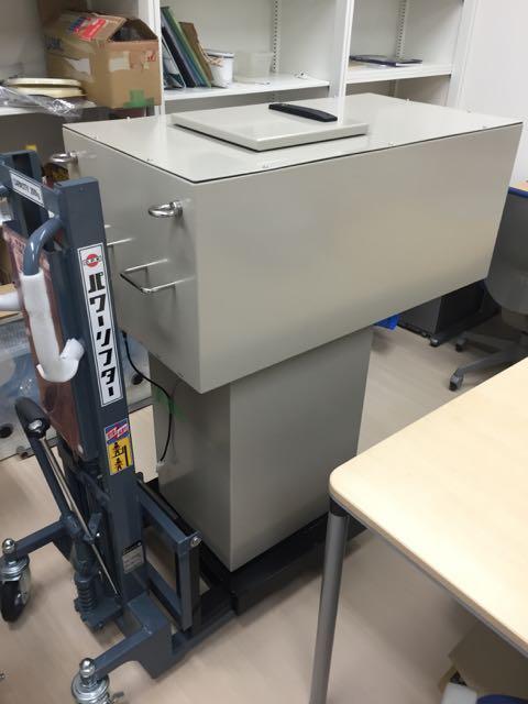
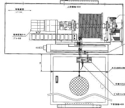
A variety of sources can be deployed through this system including optical sources for PMT and measurements of detector optical properties, and various radioactive sources. Based on previous experience at Super-K this would include a deuterium-tritium base reaction pulsed neutron generator (DT generator) to create 16N for calibration in the solar neutrino energy regime. A number of sources can be developed to provide neutrons for calibration. These include 252Cf and AmBe sources that were previously used to calibrate the neutron response of the SNO detector. These sources produce neutrons at a known rate; measuring the neutron detection efficiency and its possible variations for capture on H. If the decision is made to deploy Gd in Hyper-K, these measurements will also need to be made for neutron capture on Gd. In addition to the conventional neutron sources, we currently explore ideas for compact and pulsed neutron generator Elizondo-Decanini et al. (2012) for Hyper-K detector calibrations, that uses a similar technology to DT generator but is a palm-size portable neutron generator and can manoeuvre more effectively in detector calibrations. The neutron producion of these sources will ideally be tunable to provide single neutron calibration and also to provide the copious neutron required for calibration. Development of additional calibration sources to exploit this system can be expected over the lifetime of Hyper-K.
II.2.9.1.1.2 Integrated light injection system
Hyper-K will include an integrated light injection system for optical (absorbtion and scattering) and PMT (timing, gain and multi-photon) calibrations. This system consists of a number of light injection points connected via optical fibres to light pulsers in the electronics. Light pulses of 1-2 ns can be produced using LEDs, laser diodes (LDs) or similar solid state optical devices can be produced relatively inexpensively. This allows multiple optical sources to be deployed around the edge of the detector that can then be used for calibration. This system consists of an LED (or similar) coupled to an optical fibre, which is then connected to an optical diffuser on the PMT support structure. The optical diffuser is used to shape the light inside the detector and designs can provide different calibration pulses for different needs.
In order to maintain fast light pulses over the order 100 m distance of optical fibres required for Hyper-K graded index fibre is required rather than the step index fibre used in for example SNO+. Graded index fibre has a small active core complicating the challenge of light collection. The key challenges of this system are the coupling of the LEDs to the optical fibre, minimising dispersion in the fibre to maintain short optical pulses and achieving the required dynamic range without compromising the fast optical pulses. Research and development is currently underway in the UK to solve these problems. Figure 97 shows the current prototypes of the LED driver unit and the wide angle optical diffuser..


For some calibrations, it will be essential to monitor the light injected into the detector and this will be part of the light injection system. There are multiple options for to do this. One option is to use light that is not collected into the fibre, alternatively fibre splitters are commercially available with 99:1 split ratios allowing a small fraction of the light to be collected for monitoring. The monitoring light can be measured via optical sensors in the calibration equipment such as a monitoring PMT. The monitoring PMT signal will itself be calibrated and monitored by a dedicated monitoring channel where the main pulse is not injected into the detector, but is instead delivered to a well calibrated optical power meter. The cross calibration will allow the absolute optical signal of the monitoring system to be determined allowing comparison of light injected pulse to pulse and across the running time of Hyper-K.
This system allows PMT and optical calibration data to be taken without manpower intensive calibration source deployment that has been previously used in water Cherenkov detectors. These data either can be collected in either dedicated high rate calibrations or interspersed during data taking. This system also allows calibration to be conducted during extended periods of beam running where deployment of calibration sources would otherwise result in detector downtime. Given the systematic error budget of Hyper-K this system will mean we do not have to compromise between efficiency and the collection of sufficient calibration data.
The calibration of the PMT timing requires a short duration light pulse of known origin and time. The integrated light injection system, from any given fibre, provides this but clearly cannot illuminate the entire PMT array at once. To minimise the number of fibres required the optical diffuser for the PMT calibration is required to provide a wide opening angle, to illuminate of order 1000 PMTs on the far side of the detector. The diffuser must be carefully designed to ensure that there is no time dependence as a function of angle. To achieve the overall calibration of global time offset of the array PMTs must be illuminated by at least two fibres to allow the fibre times to be cross calibrated. We target a six-fold degeneracy of the PMT calibration fibre points to allow to for improved cross calibration and to provide redundancy against single point failures in the fibres. This system will allow for the calibration of PMT timing, the dependence of time on charge and the PMT time response.
The integrated calibration system can also be used to measure optical scattering, extinction and the PMT response. While the basic elements of the system are the same as that used for PMT calibration, a number of changes are required meaning that fibres and diffusers used for these calibrations are different. These properties are required as a function of wavelength, thus several LED types will be used to provide light at six different wavelengths between 320 nm and 500 nm. To measure scattering a narrow beam is required from the optical diffuser; the scattering length is measured by monitoring the light level of PMTs outside the narrow beam as a function of the path length of the beam through the detector. Optical absorbtion is measured by monitoring the light levels on given PMTs inside the optical beams; unlike scattering wide angle beams are important in this calibration to provide a variety of path lengths. The optical calibration system must be constructed at multiple detector levels to allow for any variation of optical properties with detector height. The pulse by pulse monitoring of the calibration system is essential for this calibration as the light level at given PMTs is the key measurement of the system. The measured light level at the PMTs is a combination of absorbtion and PMT response as a function of angle and thus several light paths and angles are required for these to be decoupled in analysis requiring a variety of diffuser points and diffuser directions to be deployed. A prototype of these systems is planned for deployment in SK-Gd. The calibration procedures and performance for the full system planned for Hyper-K will be determined using this system.
II.2.9.1.2 Photosensor calibration ex-situ
As discussed in the previous sections, many of PMT properties can be calibrated in-situ by deploying several calibration sources in the detector. We will have additional ex-situ measurements to understand further details of PMT properties that are difficult to measure in-situ.
A number of PMTs that are installed into Hyper-K must first be precalibrated to allow the gain of the detector to be tuned for uniformity. The charge recorded per photoelectron is a function of the high voltage applied to the PMT and of the PMT itself. It is important to characterise the response of a number of PMTs that are installed uniformly into the detector. Using these known PMTs once the detector is running, the high voltage applied to each PMT will be tuned such that each PMT has the same gain. In Super-K 420 PMTs were precalibrated using a Xe lamp connected via an optical fibre to a scintillator ball in a shielded dark box in which the PMT to be calibrated was mounted.
Large photo-cathode area PMTs have non-uniform charge and time responses. The photo-detection efficiency for example can vary depending on the photon incident angle and position on the photo-cathode of the PMT (e.g. Goon and Stancu (2012)). Such non-uniformity of PMT responses need to be understood and are required to build a better model of PMT responses, which is then adopted in the detector simulation. There are some difficulties to measure such non-uniformity of PMT responses after they are installed in the detector since, for example, a small non-uniformity of water transparency can make an apparent variation of PMT responses. Thus, we need to establish a special test stand for the measurements.
A test facility, called ‘photosensor test facility (PTF),’ has been built at TRIUMF. Figure 98 shows a photograph and schematic diagram of PTF.


The PTF has two manipulator arms (gantries) which are motorized and move independently in the -, -, -direction, rotation, and tilt. Each gantry is equipped with an optical box that contain a light source with a chosen wavelength, a (monitor) PMT to measure the intensity of the injected light and a (receiver) PMT which is used for measurement of reflectivity. The PTF is equipped with a water purification system, which generates ultra-pure water, and can measure PMT responses under water. As discussed in the photosensor section, Hyper-K PMT will be completely encased in a pressure housing. The optical properties of the PMT housing in ultra-pure water will also be measured by the PTF. Currently, characterization of the 20-inch SuperK PMT is under way at PTF. The ambient magnetic field is compensated down to 5mG level by a three sets of Helmholtz coils and the desired magnetic field can be applied to study the impact of the ambient magnetic field (Figure 99). Five milli-meter grid scan on the SK PMT photocathode revealed significant gain variation due to the venetian blind dynode structure. Significant gain variation due to the magnetic field is also observed (Figure 100).
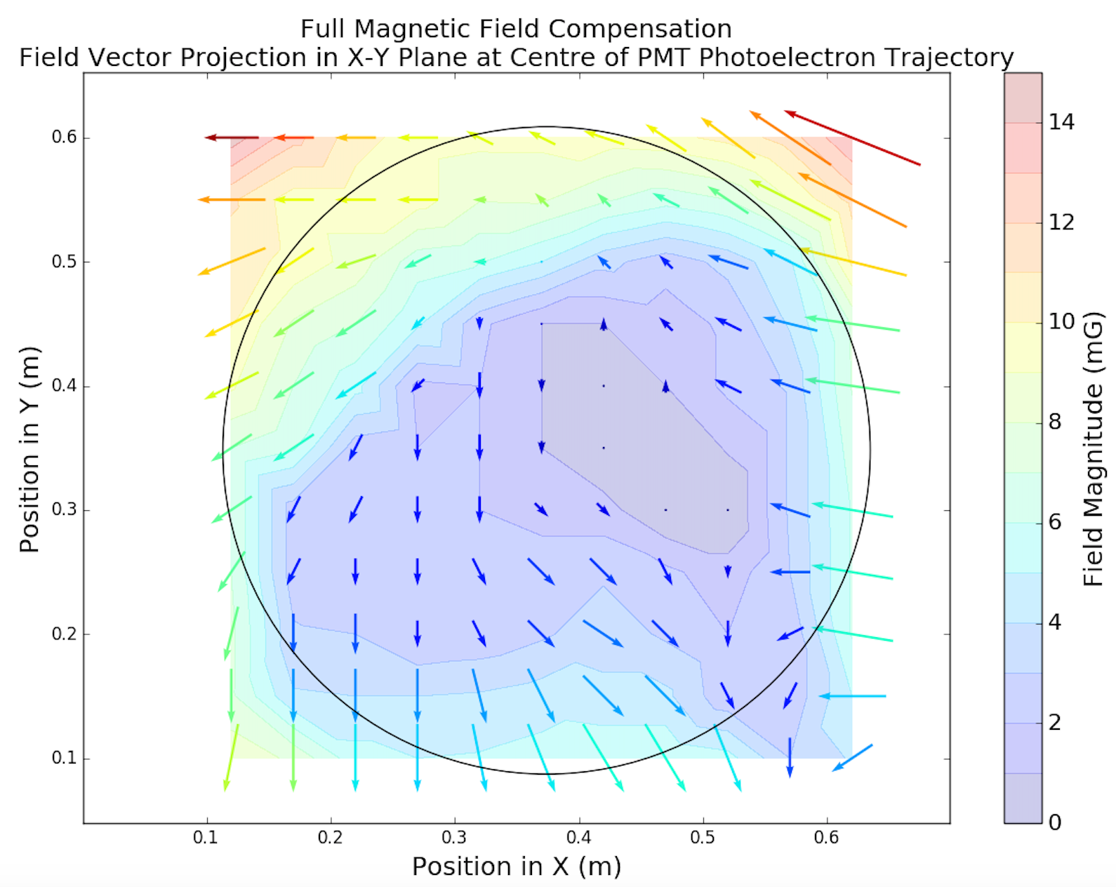 |
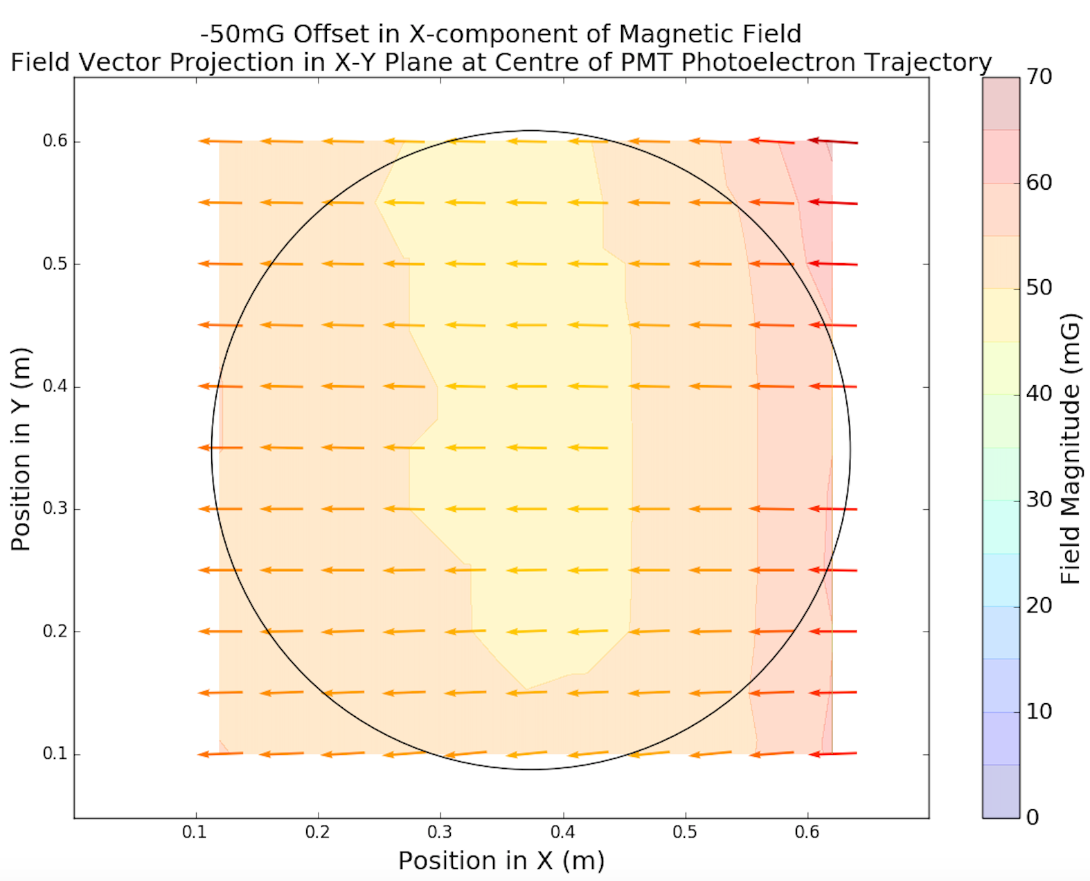 |

Calibration of the SK PMT along with the establishment of the PMT characterization procedure at PTF will continue till the end of 2017. From 2018, PTF will focus on the characterization of mPMT prototype for NuPRISM and Hyper-K and the final version of the 20-inch B&L PMT for HyperK. From 2019 PTF will focus on the design study of mPMT for NuPRISM, and then test the sampled modules for NuPRISM production. From 2022, PTF will test sampled photosensors for HyperK production till the end of 2024 when the HyperK photosensor installation starts.
In addition to PMT studies at the PTF facility, measurements of Super-K PMT properties continue at Kamioka. Initial measurements from these studies are complete and have been implemented into SKDETSIM. The impact of these measurements on physics analyses are ongoing.
II.2.9.2 Detector Monitoring
To ensure optimal detector performance, minimise systematic uncertainties and facilitate timely responses to detector problems, robust detector monitoring is essential. This will be enabled by the integrated light injection system. The integrated light injection system is being designed to allow calibration of PMT response and detector optical properties. A dedicated calibration can be performed using the system at high rate (1-10kHz) collecting sufficient statistics for each calibration channel in a short period of time. However, the system can also operate at low rate, (0.1-10 Hz) cycling through calibration channels allowing lower statistics calibration samples to be collected over the period of a few hours. Using these low statistics samples the detector calibration can be monitored for changes that might require a dedicated calibration from the inbuilt system to update the detector calibration. These monitoring pulses will also allow the health of other detector systems such as the PMT efficiency to be monitored, tracking any changes to the system as a function of time. Data from this system can be used both by experts, automated systems and detector shifters to track detector performance and understand the health of the detector.
II.2.9.3 Calibrations dedicated for physics analyses
II.2.9.3.1 Calibrations for low energy physics
In this section, detector calibration methods for so-called ‘low energy’ physics, which is a range from a few MeV to a few tens’ MeV energy region, are described. The physics targets are solar neutrinos, supernova neutrinos and geo neutrinos etc.
II.2.9.3.1.1 Review of calibration in Super-K
In the low energy physics, electrons generated by neutrino-electron elastic scattering and positrons by inverse beta decay are the detection particles. It is essential to reconstruct their vertex, direction and energy accurately for a precise observation. For this purpose, Super-K employed multiple calibration techniques.
First, an electron LINAC is used to calibrate the absolute energy scale, energy resolution, vertex and direction resolution. Single electrons with mono-chromatic energy, from 5 to 16.3 MeV, are injected from the LINAC into the detector downward at nine different detector heights. A comparison between the observed LINAC data and the Monte Carlo simulation is shown in Fig. 101. As shown in the figure, the Monte Carlo prediction and data are in good agreement after tuning. Since the LINAC calibrations require a long detector downtime and significant manpower, LINAC data are taken once per year or two years. Detail of the LINAC system and its performance can be found in reference Nakahata et al. (1999).

The decay of 16N is used to independantly check the energy calibration across the detector. Decay of 16N is dominated by an electron with a 4.5 MeV maximum energy, coincident with a 6.1 MeV ray. To create 16N, a DT generator deployed within the detector to generate the (n,p) reaction on 16O in the water, which decays with a 7.13 s half-life. After a neutron pulse the DT generator is retracted from the activated water to reduce shadowing from the calibration hardware. The DT calibrations are carried out more frequently than LINAC, that is three or four times per year. The DT calibration results are good agreement with LINAC calibration. Since 16N decay generates electrons and gammas isotropically unlike the LINAC, the DT calibration technique allows to estimation of systematic uncertainty not measured by the LINAC calibration; both the position and angular dependence of the energy scale uncertainty, for example. Detail of the 16N calibration system can be found in reference Fukuda et al. (2003). From these results, the energy scale uncertainty is estimated to be around 0.5%.
The ‘Nickel source’ is used for the calibration of the event vertex and detector uniformity. This is a 9 MeV source generated by thermal neutron capture on nickel. Neutrons are produced by the spontaneous fission of 252Cf, and a 20 cm diameter ‘nickel ball’, which consists of 6.5 kg of NiO and 3.5 kg of Polyethylene, is used. Since nickel source is easy to handle and can be deployed in the detector with good position accuracy (less than 1 cm uncertainty), nickel source calibration is carried out about every month by deploying the source at multiple locations in the detector. From this calibration, the vertex reconstruction uncertainty is estimated to be less than 5 cm. The monthly nickel source calibration also measures the variation of the detector uniformity which is caused by the water quality change.
II.2.9.3.1.2 Toward Hyper-K
For the solar and supernova neutrino detection, the similar level of precise calibration to Super-K is needed for Hyper-K. Many of calibration sources used in Super-K, like nickel source, can also be used in Hyper-K, however, employing an electron LINAC system requires further considerations since Hyper-K will have a larger volume than Super-K, that causes a much larger burden to operate LINAC calibration system at Hyper-K. Thus, alternative approaches to the LINAC calibration are being developed. One possible approach can be the following. Super-K detector simulation is tuned with LINAC calibration data, and the LINAC-tuned simulation reproduces DT calibration data very well, as described above. By adopting the tuning parameters of the LINAC-tuned Super-K simulation in Hyper-K, DT calibration data of Hyper-K can provide a good calibration of the absolute energy scale without employing LINAC calibrations in Hyper-K. This way does not requires LINAC calibrations at Hyper-K but requires an intensive DT calibrations. For the purpose, a compact DT generator or an alternative neutron generator would be desirable. In order to calibrate the energy regime, up to a few tens MeV, which is higher energy than DT calibration, we need to develop new calibration sources. These new systems are under development.
The decision for the inclusion of the LINAC within HK will require resources such as the purchase of a new LINAC and the production of an extra cavity to house it. As such this decision is a significant milestone for the HK calibration design requiring further study before it can be made. We aim to make this decision prior to the end of 2018.
II.2.9.3.2 Calibrations for high energy physics
In this subsection, the energy scale calibration of the inner detector for the higher-energy physics analyses (atmospheric neutrino oscillation, nucleon decay search, T2K, etc.) is described.
II.2.9.3.2.1 Review of calibration in Super-K
The charge scale of the SK detector simulator (SKDETSIM) is initially calibrated by measuring each PMT quantum efficiency, single photo-electron charge distribution, etc. by using various control samples such as the nickel source. A global correction factor which scales the total photo-electron yield is then tuned in SKDETSIM using cosmic-ray through-going muons.
After this correction, particle momentum is reconstructed as follows: the total integrated corrected charge from all the hit PMTs within a 70 degree cone from the reconstructed vertex with respect to the reconstructed ring direction is measured for each ring. The correction of the charge is done for each hit PMT by taking into account the photon acceptance as a function of the incident angle to the PMT and the light attenuation length in water. The corrected charge is converted to momentum by using a conversion table made with MC for each particle type assumption. For multi-ring events, the momentum for each ring is determined by separating charge for each hit PMT to maximize agreement of observed and expected ring charge pattern according to the particle type assumption determined by PID. For the expected charge calculation, photon scattering in water and reflection at the inner detector wall are taken into account. Time variation of the attenuation length and PMT gain is taken into account and the momentum is corrected in the real data.
| SK-I | SK-II | SK-III | SK-IV | |
|---|---|---|---|---|
| Absolute Energy Scale | 0.74 | 1.60 | 2.08 | 2.4 |
| Time Variation | 0.88 | 0.55 | 1.79 | 0.41 |
| Total Energy Scale | 1.1 | 1.7 | 2.7 | 2.4 |
| Directional Dependance | 0.6 | 0.6 | 1.3 | 0.8 |
Tabel 27 summarises the energy scale uncertainties in Super-K. Figure 102 shows the result of a comparison of the energy scale between data and MC from around 10 MeV/c to 10 GeV/c, using cosmic-ray stopping muon and associated decay electron data, and data produced in atmospheric neutrino interactions in SK-IV.

The absolute scale error is estimated to be 2.4% from the largest difference between data and MC which occurs in the sub-GeV stopping muon sample. Note that the global momentum scale for data was adjusted typically in the end of each SK detector period to minimize the absolute scale error but has not been done yet in SK-IV. The time variation of reconstructed momentum is shown in Fig. 103 and Fig. 104.


For the entire SK-IV time period, the momentum has been stable to within 1% and the time variation (RMS/mean) is estimated to be about 0.4%, taken as the largest value between these two calibration sources. By taking the quadratic sum of the absolute scale error and the time variation, the energy scale error is estimated to be 2.4% in SK-IV. Further, the directional dependence of decay electron momenta is used to estimate the asymmetry of the energy scale. The asymmetry was estimated to be 0.8% in SK-IV.
Fig. 105 shows the absolute energy scale checks from SK-I to SK-III.
 |
 |
 |
There have been a number of changes to SK over its running period. In SK-II the photo-coverage was reduced to 20% from 40%, and PMT acrylic covers were installed from this point on. From SK-III photo-coverage was restored to 40% and new readout electronic modules were installed from SK-IV. Despite these changes, the absolute scale error remains at about 1-2% from SK-I through SK-IV. The absolute energy error is estimated to be 0.74%, 1.60%, and 2.08% for SK-I, SK-II, and SK-III, respectively.
Figure 106 shows the result of the momentum time variation (RMS/mean) from SK-I to SK-III.

The time variation during SK-I, SK-II, and SK-III was 0.88%, 0.55%, and 1.79%, respectively. The time variation in SK-III was relatively larger due to worse water quality and it is at a minimum in SK-IV due to improved momentum time variation correction for SK-IV. During SK-I, SK-II, and SK-III, the directional dependance of the momentum was estimated to be 0.6%, 0.6%, and 1.3% respectively.
II.2.9.3.2.2 Toward Hyper-K
To achieve the physics goals of Hyper-K we must achieve an uncertainty in the momentum scale as has been achieved in Super-K. In current analyses of Super-K data involving, atmospheric neutrinos, neutrinos from the T2K beam and nucleon decay, systematic uncertainties are dominated by uncertainties in the physics model, such as cross section uncertainties. We aim to reduce these for Hyper-K, but they are still likely to be larger than the current Super-K momentum scale uncertainty. We aim, in the first instance, to match the current Super-K uncertainties, and to over the duration of the experiment make further improvements to reduce these uncertainties further.
Thanks to the similar vertical cylindrical tank, there is no major concern which makes the energy scale error significantly larger in Hyper-K.
The current energy scale error in SK-IV comes from the unknown momentum dependence of the absolute scale, especially as seen in the sub-GeV stopping muon sample. The muon momentum of the sub-GeV sample is below about 500 MeV/c where the Cerenkov angle significantly depends on the momentum. Each sub-sample of the sub-GeV sample is defined by using the reconstructed Cerenkov angle. The Cerenkov angle reconstruction depends on the charge profile shape which is especially affected by the tuning of the scattering parameters in SKDETSIM. As Hyper-K is significantly larger than Super-K the variation of water properties across the detector, especially the vertical dependence, becomes more of a concern. To address this analysis of light from horizontal injectors at different depths is being developed in Super-K and will form an important part of the Hyper-K calibration program where better understanding of the water quality is important.
As the sophistication of reconstruction and calibration continues to increase, addressing the various contributions to the momentum scale uncertainty and improving our understanding of their effects, we can expect the overall systematic uncertainty to continue to improve. A recent example of this includes the improvement of the PMT gain time variation correction in to SK-IV analysis, reducing the time variation with respect to that from SK-I-III. Further improvements can be expected over time, through Super-K and into the Hyper-K era.
II.2.9.4 OD calibration system
The major task of the OD part of the Hyper-K detector is not to obtain the exact energy deposited but to identify the neutrino events out of the cosmic-ray muons. For example, “fully contained” events are identified by requiring no energy deposition in OD, and “partially contained” events and “upward-going muon” events, which are important sub-samples in atmospheric neutrino analyses, are identified with OD hits coinciding with ID hits. For these physics analyses, an ‘inter-calibrations’ between OD and ID, e.g. timing calibrations between OD and ID, is also important in addition to the calibrations of OD itself.
Compared the ID part, the OD has various disadvantages in having a calibration system. They are: 1) many light injection points are necessary to illuminate all the light sensors in the OD area to an intensity level of a few 100 PE’s, 2) there are sensor support structures which can hinder the delivery of calibration light, and 3) there is no easy way to deploy additional light injection points to replace non-functional ones once the detector is filled with water. The latter 2 points can be mitigated by having redundant light injectors, but this will certainly increase the total cost of the system.
In the case of Super-Kamiokande experiment, the OD calibration system consists of a and a dye laser, monitoring PMT’s, a variable attenuation wheel, optical switches, and 52 fibers. Each fiber is equipped with a light diffusing tip at the end. Of these fibers, 24 are placed in wall section and 14 each are placed in top and bottom sections. They are 72 m long, except for those placed in the bottom section which is 110 m long. In average, each wall fiber covers 160 m2 of OD sensor area and about 2.5 m away from the OD PMT plane. Top and bottom fibers cover 64 m2 per fiber and about 1.6 m away. These fibers are reasonably redundant and a little over a half of them are actually used to calibrate all the OD PMT’s.
For the SK OD calibration system to be adopted to the Hyper-K detector, 79 fibers are required to achieve the same fiber density as the SK for the Hyper-K wall section. For top and bottom, 61 each is necessary. In total, 201 fibers are needed for the entire Hyper-K detector. In terms of length, 200 m fibers for bottom and 120 m ones for other sections are necessary to compensate the linear dimension difference between the SK and Hyper-K detectors.
II.2.10 Computing
Hyper-K adopts a Tiered computing model where Kamioka and KEK sites form the Tier-0 due to the distributed nature of the experiment. A general overview of a future Hyper-K tiered system is shown in Fig. 107.

The Tier0 sites will hold the raw experiment data as well as the processed data. The KEK Tier0 will also contain a The Tier1 centres (such as RAL, TRIUMF, ccin2p3) would hold portions of the raw, processed and simulated data and provide computational resources for the simulation, processing and reprocessing. The Tier2 sites which typically consist of universities will provide computational and storage resources (the storage is usually used to hold specific subsets of the data or simulation). The model makes efficient use the available computing resources that exist at collaborating sites. The model will be regularly reviewed as changes to the computing landscape take place.
A current estimate of the rate of raw data to be stored is 20 TB/day. About 80 PB of the disk space is necessary to store the raw data for the 10 years operation.
Reduction and reconstruction software will be applied to all the data in the Kamioka Tier0 as soon as the data are taken to provide different samples for different energy regions or different analysis groups, i.e. low energy region mainly for the study of solar neutrinos, higher energy for the study of nucleon decay and atmospheric neutrinos, downward going muons for the background study of solar neutrinos, the data during the beam timing from the accelerator for the beam neutrino analyses. These data sets also provide timely feedback to the experiment and beam operations groups on the quality of the beam and performance of the detector. Also, early detection of a supernova burst is crucial and dedicated realtime analysis has to be performed in the independent system. The required computing power for data reduction and reconstruction at this level, together with the supernova detection system, is not so huge and 1000 cores of the current Intel IA64 CPUs will be sufficient.
II.2.10.1 Simulation production
Mass production of the simulation data sets and their analyses are expected to be performed in the Tier-1 centres because the required CPU resource for the huge amount of simulation data is expected to be at least a few tens of times larger than the ones necessary for the real time data processing. On the other hand, the simulated data set is not extremely large and the cost of the storage could be less than 10% of the storage for the real data sets. All the data sets after reduction and the processed simulation data sets are shared among the geographically distributed analysis working groups. The Tiered model ensures results in a more scalable architecture capable of meeting the computational and storage demands of the experiment.
The Monte Carlo simulation production currently makes use of existing HEP computational Grid resources to produce sufficient quantities of physics events necessary to optimise the detector design for maximum efficiency. The data are managed by the iRODS data management system (http://irods.org/) that enables distributed storage to be managed and accessed in an uniform manner. Collaborators access the stored data using the intuitive and simple iRODS client API.
II.3 Hyper-Kamiokande software
The Hyper-K software system is designed around the following principles:
-
•
Adaptable. The Hyper-K experiment is expected to run for more than a decade. This period typically spans more than one generation of software and infrastructure. The Hyper-K offline system is being designed to be flexible enough to accommodate changes in tools or infrastructures.
-
•
Reliable. Each component needs to demonstrate it’s reliability by exhibiting well defined behaviour on control samples.
-
•
Understandable. Documentation on what the component does, what it’s dependencies are as well as test samples and outputs are essential in being able to use it successfully.
-
•
Low overhead. The management and maintenance should be as automated as possible to free collaborators to focus on the challenge of extracting the high-quality physics measurements.
The software consists of a collection of loosely-coupled packages, some of which are open-source and some of which are specific to Hyper-K. The distributed code management system Git git is used to manage the software. Each package is hosted on a third-party central repository (https://github.com/) that provides distributed access to the packages. The distributed nature of the code management allows researchers the possibility to develop the software independently without impacting other researchers. The loose-coupling between packages allows those that reach their end of life to be replaced by better alternatives with minimal impact on the rest of the system. Where possible standard particle physics software libraries are used to reduce the burden of support of experiment-specific code. The working language for the Hyper-K software packages is C++, with the output files being written in ROOT Brun and Rademakers (1997) format.
The flow for the simulation is as follows: The event topologies are generated by a neutrino interaction package(GENIE Andreopoulos et al. (2010) and NEUT Hayato (2009), for example), and modeled by a Monte Carlo detector response code called WCSim WCS . The event information is reconstructed using either BONSAI M.Smy (2007) (for low energy events) or fiTQun (for high energy events) Tobayama (2016). This is shown schematically in Figure 108. These packages will be described in more detail in the next Sections.
An online workbook is also maintained to provide higher-level documentation on overall procedures and information for new users of the software and developers. An overall software control package allows for the fully automated download, compilation and running of the software, based on user requests.

II.3.1 WCSim
The Water Cherenkov Simulation (WCSim) package is a flexible, Geant4-based code that is designed to simulate the geometry and physics response of user-defined water Cherenkov detector configurations. WCSim is an open-source code and is available for download at https://github.com/WCSim/WCSim.
The final performance of the Hyper-Kamiokande detector depends on the detector geometry, the type of photodetectors, and the photocoverage that will be used. WCSim takes these variables as inputs and simulates the detector response, which can then be used to determine the physics potential. WCSim users specify the type of photodetectors, the number of photodetectors, the detector diameter and radius, and whether the water should be doped with gadolinium. The outer detector volume is currently not implemented in WCSim, though it is actively being developed for a future release.
For this report, the relevant photodetectors in WCSim are the R3600 20” diameter PMTs, as well as the R12850 20” and 12” diameter box and line photodetectors. Photodetector parameters in the simulation include the timing resolution, dark noise rate, and the overall efficiency for a photon to register a charge (including the quantum efficiency, collection efficiency, and hit efficiency as described in Section II.2.6). For the R3600 PMTs, the parameters were taken from the Super-Kamiokande simulation code SKDETSIM. The parameters for the R12850 are taken from measurements as described in Section II.2.6. Some higher-level photodetector effects such as after-pulsing are not currently simulated in WCSim, though this is a planned upgrade for a future releases.
Geant4 Agostinelli et al. (2003) is used to track the particles as they pass through the detector and compute the final deposited energy. Particles that reach the photodetector glass and pass the quantum efficiency and collection efficiency cuts are registered as a hit. The hits are then digitized based on the SK-I electronics scheme, though the code has the flexibility for users to include their own custom electronics configurations.
The output for the WCSim code includes both the raw hit and the digitized information. The raw hit information includes which tubes were hit and how many times each tube was hit. The digitized information includes the number of hits in a trigger window, as well as the charge and time of the hit tubes. WCSim output files can be used for event reconstruction by fiTQun or BONSAI, which are described in the following subsections. Geant4 visualization tools can be used to display the detector geometry and particle tracks. Figure 109 is a rendering of one of the proposed Hyper-K tanks. Figure 110 shows an example of an event display for an electron and for a muon, each with 1 GeV kinetic energy.

 |
 |
Figure 111 shows how the flexibility of WCSim can be used to explore different detector configurations. Here, the total charge distribution for electrons and muons at several momenta in the Hyper-Kamiokande detector with two different photocoverage options are shown. RMS divided by mean charge is plotted in Figure 112 indicating better resolution with 40% photocoverage than with 14% photocoverage. For lower energy particles, the resolution can be approximated using nhits (the number of phototubes that register a hit). The nhit distribution for both 14% photocoverage and 40 % photocoverage are shown in Figure 113.
 |
 |
 |
 |
 |
 |
II.3.2 FiTQun
FiTQun is an event reconstruction package initially developed for the Super-K detector based on the formalism used by the MiniBooNE experiment Patterson et al. (2009). The reconstruction algorithm allows for single- and multiple-ring event hypotheses to be tested against observed data. For a given event hypothesis, a prediction is made for the complete set of observables at each PMT. This includes whether or not the PMT was hit, and for hit PMTs, the hit time and integrated charge. The hypothesis and associated kinematic parameters that best describe a given event are found by maximizing a likelihood function of the prediction with respect to the observed data.
FiTQun has been shown to perform well on Super-K data, with significant improvements on vertex, angle and momentum resolutions, as well as particle identification when compared to previous reconstruction algorithms. In particular, fiTQun was successfully deployed to reject events from the Super-K sample in the T2K appearance analysis (Figure 114) Abe et al. (2014b, 2015c).

II.3.2.1 Reconstruction algorithm
At the core of fiTQun lies a likelihood function, which is evaluated over all the PMTs in the detector:
| (15) |
Event hypotheses are characterized by , which includes the time and position of the interaction vertex, momentum and direction of the charged particle tracks, and any other relevant kinematic parameters such as the distance or time interval between tracks, or the energy lost between track segments. For a given , a prediction of the amount of charge at each PMT, , is made and the time at which the light is expected to arrive each PMT is calculated.
The detector response is folded into these predictions to give the probabilities of a PMT being hit and the read-out time and charge probability distribution functions and , respectively. The negative log-likelihood () is maximised to obtain the that best describe the event according to some event topology (e.g., single electron-like ring).
Once the best-fit parameters have been obtained for several topologies, the ratio between their likelihoods is used to determine which topology gives the best match to the event. This can be used as a particle identification tool if simple one-particle hypotheses are used, or as a more complex selection criterion if multiple final-state particles are included in the hypothesis (e.g., a nuclear de-excitation photon followed by a decay muon for the selection of events).
II.3.2.2 Integration with WCSim and tuning
FiTQun has been adapted to reconstruct events simulated with WCSim, in the various detector configurations implemented in the simulation software. A C++ class was written (WCSimWrapper) that reads in both detector geometry (positions and radius of PMTs) and event data from the WCSim ROOT output files. A preprocessor flag allows fiTQun to be compiled against WCSim libraries, removing its dependence on Super-K software.
In the context of WCSim, events can be generated in an arbitrary number of detector configurations. For fiTQun to adequately reconstruct events in any given configuration, some of its components have to be re-evaluated. For example, the charge and time response of PMTs must be accurately known in order to obtain unbiased estimates of particle momentum and vertex position. The tuning procedure developed for Super-K and SKDETSIM was adapted to be used with WCSim and with generalized cylindrical geometries.
The tunes produced for each simulated detector consist of ROOT files and run-time parameters. A configuration file (that contains the information needed by fiTQun to load the appropriate files and parameters) is given for each tune. These configuration files are packaged with fiTQun, such that any tune available can be selected in a single step.
II.3.3 BONSAI
For event reconstruction at low energy, i.e. few MeV - few tens MeV, a reconstruction algorithm BONSAI (Branch Optimization Navigating Successive Annealing Iterations) is supplied for Hyper-Kamiokande. BONSAI was originally developed for Super-Kamiokande M.Smy (2007) and written in C++. It has been used for the low energy physics analysis of SK-I to SK-IV. In the low energy region, most of the photosensor signals are single photon hits. BONSAI uses this relative hit time information to reconstruct the position of the Cherenkov light source, i.e. the position of low energy event. For Hyper-K analysis, a wrapper library (libWCsimBonsai) is supplied for ROOT environment.
II.3.3.1 Vertex reconstruction
For the vertex reconstruction, BONSAI performs a maximum likelihood fit using the photosensor hit timing residuals. This likelihood fit is done for the Cherenkov signal as well as the dark noise background for each vertex hypothesis. The likelihood of the selected hypothesis is compared to the likelihood of a hypothesis in an area nearby. Highly ranked hypotheses and new points in the likelihood will survive this step. Finally, after several iterations, the hypothesis with the largest likelihood is chosen as the reconstructed vertex.
The vertex goodness criterion testing the time residual distribution
is defined as follows:
| (16) |
where are the measured PMT hit times, the photosensor locations, is reconstructed event vertex, is the effective timing resolution expected for Cherenkov events (total of photosensor and DAQ resolution). is the group speed of light in the water, i.e. with the speed of light in vacuum and refractive index . are Gaussian hit weights also based on the hit time residuals, but with a much wider effective time resolution. The weights reduces the dark noise contamination of the Cherenkov light. A result of vertex reconstruction performance study with BONSAI and WCSim can be found in the figure 115. More Cherenkov photons could be detected with new photosensors for Hyper-K and it improves the reconstruction results, comparing to those of Super-K Though, at same time, the random photosensor signals caused by their dark pulse can spoil the merit. So reducing dark pulse is a crucial factor to improve the low energy event detection. Many efforts for the dark pulse reduction (II.2.6.2.1.5) and improvements of the softwares are being continued.

II.3.3.2 Energy and direction reconstruction
BONSAI and its related subroutines also determine the energy and the
event direction reconstruction.
Because most of the photosensor signals consist of single photon hits at low energy below few tens MeV,
the total number of photosensor hits is the leading parameter for
reconstructing the energy of events. First, time-of-flight values are
subtracted from each of the hit timing values based on the position of
each photosensor and the result of the BONSAI vertex reconstruction.
Next, the number of photosensor hits around the expected event timing
is calculated, considering its cross-section and the local
photocoverage with neighboring photosensors. Finally, the number of
hits are scaled to energy using the information from detector
simulations and calibrations.
The direction reconstruction is also performed on the photosensor hit
patterns using a circular KS test that checks the azimuthal symmetry
around the Cherenkov cone.
As the result, the vertex position, direction and energy of low-energy
events are available after BONSAI reconstruction.
Several likelihoods to test mis-reconstruction are also available during the reconstruction. Likelihoods calculated using photosensor hit patterns are also used in particle identification, e.g. to differentiate between electron and gamma events.
II.4 Background rate estimation
II.4.1 Background rate estimation for low energy neutrino study
In this subsection, we will show the background rate estimation used for the study of low energy neutrinos, such as solar neutrinos, supernova neutrinos, and relic-supernova neutrinos. The most important background sources are the radioactive isotope of 222Rn contained in water, and radioactive spallation products created by cosmic-ray muons. Other important radioactive isotopes are U and Th in the water, and 40K in the PMT glass; we need to suppress the concentration of those isotopes to the similar level in Super-K as well. On the other hand, the major background sources for the anti-neutrino measurement is anti-neutrino backgrounds from nuclear power reactors, which limit the energy threshold at around 10 MeV; the smaller contribution comes from the radioactive background of reactions. In the background calculation, the most complicated task is the estimation of the muon spallation productions and its background reduction by the analyses, because it depends on the detector location and the detector performance. In the following paragraphs, after discussing radon backgrounds, we focus on the discussion of the muon spallation backgrounds.
II.4.1.1 Radon background
Radon (222Rn) is a radioactive noble gas, with a half-life of 3.8 days. 222Rn occurs as a daughter nuclide in the 238U decay scheme, via the decay of 226Ra ( years). Small but finite quantities of 226Ra exist in all materials and therefore, every material can produce 222Rn. As a gaseous isotope, 222Rn can easily escape from materials used in the construction of Hyper-K and the radioactivity content of construction materials must be carefully screened. The decay of 222Rn produces several daughter isotopes, most of which are not sufficiently energetic to produce Cherenkov light in the Hyper-K detector. The most serious background for solar neutrino measurements is the radon daughter bismuth-214 (214Bi) which decays via beta emission with a Q-value of 3.27 MeV. This limits the energy threshold of the solar neutrino measurements in which a neutrino-electron elastic scattering reaction is used.
In the same energy region, 208Tl in thorium series could become another serious source of the background. However, from the results of radon assay with special radon detectors Takeuchi et al. (1999a); Mitsuda et al. (2003) in Super-K, the contamination of the radon in thorium series (220Rn) looks much smaller than that of 222Rn in Super-K water. So, we discuss only 222Rn in this section.
Typical radon concentrations in Mozumi mine and Super-K are summarized in Table 28.
| Detector site | Radon concentration |
|---|---|
| Mine air in Mozumi Takeuchi et al. (1999b) | [Bq/m3] |
| SK-I inner detector water (upper half) Takeuchi et al. (1999b) | [mBq/m3] |
| SK-I inner detector water (bottom) Takeuchi et al. (1999b) | [mBq/m3] |
| SK-IV supply water | [mBq/m3] |
| SK-IV return water | [mBq/m3] |
The SK-IV return water is taken at ton/hour from inner detector and at ton/hour from outer detector Abe et al. (2014f). So, we think the radon concentration in the SK-IV outer detector is close to (or larger than) that in the SK-IV return water. From the event rate comparison between SK-IV and SK-I, the radon concentration in SK-IV inner detector is similar or less than that of SK-I. Therefore, the radon concentration would be different by several factors between inner and outer detectors in SK-IV. However, in Super-K detector, water flow is controlled well by temperature and flow rate balances Abe et al. (2014f), and then the water condition in inner detector has been stable. Figure 116 shows a vertex distribution of the final data sample of the solar neutrino analysis in SK-IV.

The remaining event rate in the central detector is kept low while the barrel and bottom of the detector are higher than that. This shows the water flow control in Super-K detector works well. For the solar neutrino measurements, a threshold of 4.5 MeV (electron kinetic energy) in 22.5 kton fiducial volume was achieved in Super-K I.
In this design report, we estimate the radon concentration in the Hyper-K tank water would be about 1.6 in average in whole detector, as described in section II.2.5.5. When applying the same water flow control technique as Super-K, the radon concentration in the central Hyper-K detector will be reduced.
Moreover, we could suppress 214Bi events thanks to better photon yield in Hyper-K. Figure 117 shows expected observed energy spectrum of beta decay of 214Bi in Super-K and Hyper-K.

At 4.5 MeV (electron kinetic energy), a suppression about factor 10 is expected in Hyper-K detector comparing to Super-K detector. Actually, we have observed an expected energy resolution difference due to photon yield change between SK-I and SK-II.
Another possible difference among Super-K and Hyper-K detectors related to radon background would be the lining material of the detector. As discussed in section II.2.4.2, 5 mm thickness HDPE will be used to line the Hyper-K detector, and radon could permeate a HDPE sheet. Typical radon permeability through a HDPE sheet is reported by various groups as cm2/s Ashrya et al. (2011); Jiranek (2004); Mamedov et al. (2011); Rau (2012); Fernandez et al. (2004).
As shown in Table 28, the typical radon concentrations are different by about 5 order of magnitude between mine air and Super-K OD water. For Hyper-K, radon concentration in OD water through the radon permeation from outside detector into Hyper-K detector could be estimated as mBq/m3 in Hyper-K OD water under several assumptions, like (1) a radon permeability of the Hyper-K HDPE sheet is cm2/s, (2) radon concentration in mine water (spring water in the mine) is Bq/m3, (3) there is no water flow between Hyper-K ID and Hyper-K OD, and (4) the volumes of mine water and Hyper-K OD water contributing to this effect are similar. This estimation gives a similar radon concentration in Super-K OD detector, though the uncertainty is large.
In order to reduce the uncertainty of (1) in this estimation, we are planning to measure radon permeability of a Hyper-K HDPE sheet. Figure 118 shows a device to assay radon permeability through a sheet in Kamioka.

The performance of the device is still under tuning, but the current sensitivity on radon permeation assay is about cm2/s for a 1 mm thickness sheet. Therefore, this device has enough sensitivity to test the Hyper-K HDPE sheet.
In order to achieve (3) in Hyper-K, we are designing more hermetic ID detector to reduce water flow between ID and OD. We also apply the same water flow control techniques realized in Super-K to keep radon around detector wall in Hyper-K ID.
As a summary, applying the same radon reduction techniques developed in Super-K, a similar radon concentration in Hyper-K inner detector water is expected. The radon permeation through lining material might increase, but an initial estimation shows a similar level of the radon concentration in outer detector water in Hyper-K. In order to avoid increase of radon in inner detector, we are planning more hermetic inner detector. We are going to measure radon permeation of our liner candidates, too. Moreover, about factor 10 tolerance is expected at 4.5 MeV thanks to improvement of the energy resolution. Therefore, we think 4.5 MeV (electron kinetic energy) threshold for solar neutrino measurements would be feasible in the Hyper-K detector.
II.4.1.2 Muon spallation
Radioactive isotopes produced by cosmic-ray muon-induced spallation are potential backgrounds for low energy neutrinos. Generally, the production rate depends strongly on the muon flux and the average energy, and the delayed radioactive decays cause the backgrounds in the energy region below about 20 MeV. If the lifetime of radioactive isotope is relatively short on the order of a few seconds or less, the spallation backgrounds can be mitigated by time/volume cuts based on the reconstructed muon track. Therefore, the detailed estimation of the cosmic-ray muon intensity and the spallation production rate are of great importance in demonstrating the sensitivity of Hyper-K to low energy neutrinos.
The muon intensity at the planned site can be estimated using the calculated surface muon flux and energy, the mountain profile, the rock density and compositions. The muon flux () and average energy () at underground sites are estimated by the muon simulation code (MUSIC) Antonioli et al. (1997), a three-dimensional MC tool dedicated to muon transportation in matter. In this MC, surface muons are generated according to the Modified Gaisser Parameterization Tang et al. (2006) sea-level muon flux distribution. A digital map of the topological profile of Nijuugo-yama with a 5 m mesh resolution Geo (2010) is shown in Fig. 119. The Hyper-K detector will be located around the basing point at the altitude of 508 m, referenced in Section II.2.2 corresponds to a position under the old mountain peak before the surface mining. Based on this elevation data, we calculate slant depths as a function of zenith and azimuth angle at an arbitrary point of Hyper-K candidate sites, and estimate the survival probability of muons after the muon transportation through the rock for each angle using the MUSIC simulation.

Previously, the value of and at KamLAND in Ikeno-yama are evaluated based on the MUSIC simulation for various rock types Tang et al. (2006); Abe et al. (2010). The value of is dependent on the type of rock. Varying the specific gravity of rock from 2.65 to 2.75 in the MUSIC simulation yields values of that agree with the KamLAND muon flux measurement Abe et al. (2010). As both Nijuugo-yama and Ikeno-yama are skarn deposit, which are common characteristic in the Kamioka mine, the simulation for Hyper-K assumes the same rock type used in Ref. Abe et al. (2010). Figure 120 shows the calculated and for Hyper-K at the altitude of 508 m for 2.70 specific gravity Ikeno-yama rock. The values of and vary greatly depending on the shallowest rock thickness on the west or south side, as indicated in Fig. 119.


Table 29 summarizes the calculated and in Hyper-K and Super-K for 2.70 specific gravity. Considering the variation of for different rock types, we assume uncertainties of 20% for . Because the Super-K site is deeper, the value of for Hyper-K is higher than Super-K by a factor of 4.9. On the other hand, the value of for Hyper-K is smaller than Super-K as indicated in Fig. 121, because the relative contribution of lower energy muons becomes larger at a shallower site. Figure 122 shows the muon flux as a function of zenith angle (upper) and azimuth angle (lower) for Super-K and Hyper-K at the basing point. We confirmed that the MUSIC Monte Carlo simulation has been shown to be in good agreement with the Super-K data, as shown in Figure 122. In Hyper-K, the major contribution of muon flux is introduced by the flux in the west and the south.
| Detector site | Vertical depth (m) | () | (GeV) |
|---|---|---|---|
| Hyper-K (basing point) | 600 | 7.55 | 203 |
| Super-K | 1,000 | 1.54 | 258 |


Based on the muon flux and energy spectrum calculated by the MUSIC simulation, we can estimate the isotope production rates by muon spallation in a planned detector. FLUKA can be used to reliably model nuclear and particle physics processes involved in muon spallation. Previously, the measured isotope production rates in a underground detector were compared with the FLUKA simulation Abe et al. (2010). However, owing to large uncertainties on the isotope production cross sections by muons or their secondaries, the production rate between data and MC differ by up to a factor of two, as shown in Table V of Ref. Abe et al. (2010). In order to minimize the uncertainties, we use the isotope production rates observed in Super-K as a basis, and the values in Hyper-K are estimated based on the muon flux ratio calculated by MUSIC and the isotope yield ratio by FLUKA,
| (17) |
where is the production rate per unit volume for isotope , the muon flux (), the yield per muon track length () for isotope . We use FLUKA version 2011.2b to estimate the isotope yields in Hyper-K and Super-K. A water-filled volume of 40-m square and 40-m length is used in the simulation, and the analysis of isotope productions is limited within the inner volume of 40-m square and 20-m length in order to avoid a boundary effect. To include the muon charge and energy dependence in isotope production yields, beams of both and with a calculated energy spectrum produced by MUSIC were simulated, and the isotope yields by and are combined based on their weighted average assuming that a relative intensity of to is 1.3. Table 30 shows the estimation of isotope production yields for Hyper-K and Super-K, the ratio of isotope yields, . The ratio of the production rates, , are also calculated by multiplying the isotope yield ratio by the muon flux ratio, , which was evaluated from the MUSIC simulation. We assume uncertainties of 20% for the muon flux ratio considering the possibility of different rock types for the Hyper-K and Super-K sites. The resulting increase in isotope production rate per unit volume from Super-K is approximately a factor of in Hyper-K, which is used for studies of the Hyper-K physics potential in the following sections.
| Isotope yield by FLUKA (/m) | Ratio of isotope yield | Ratio of production rate | ||
|---|---|---|---|---|
| Isotope | Hyper-K | Super-K | (Hyper-K / Super-K) | (Hyper-K / Super-K) |
| 12B | ||||
| 12N | ||||
| 9Li | ||||
| 8Li | ||||
| 15C | ||||
| 16N | ||||
| 11Be | ||||
II.4.1.3 Muon spallation background reduction
The spallation products as backgrounds have their origin in the spallation reaction of the cosmic muons. Therefore, we can identify and remove these spallation products if we compare their four-dimensional correlation with corresponding muons. In this section, we will discuss the muon spallation backgrounds using these correlations. The spallation reduction method is being used in supernova relic neutrino searches at Super-K.
II.4.1.3.1 Method of muon spallation background reduction
We apply a likelihood ratio test on low-energy events to reduce
spallation backgrounds. The detail is discussed below.
With water
Cherenkov detectors, such as Super-K or Hyper-K, we
can measure the times, positions and energies of the spallation
products and their preceding muon tracks. It is also possible to
measure the energy deposit per unit length along muon tracks,
by deconvoluting Cherenkov ring hits. The peak position of
distribution can be assumed as the position where muon spallation
occurs.
We use following valiables for spallation background reduction.
-
•
Time difference , between the low-energy event and the preceding muon.
-
•
Transverse distance , which is defined as the perpendicular distance from the muon track to the low-energy event.
-
•
Longitudinal distance , which is defined as the horizontal distance from the peak position of on reconstructed muon track and the low-energy event.
-
•
Residual charge , which is the amount of light seen in dE/dx distribution in a width of 4.5 m centered on the peak.

A schematic figure of spallation distance variables are shown in Figure 123. Their actual distributions can be found in a reference Bays (2012). The probability density functions and of each valuables are given from the fitting results of actual spallation candidates and non-spallation (random) event samples, respectively. The likelihood ratio is defined using PDFs as follows:
| (18) |
Because any preceding cosmic muon can be a cause of spallation backgrounds, we calculate the likelihood ratio with all muons within 30 seconds before the low energy event. The largest likelihood ratio is adopted as the value for the low energy event. We can arbitrarily choose the cut value for the likelihood ratio, which defines the reduction efficiency and the signal efficiency.
II.4.1.3.2 Estimated muon spallation background after reduction
When we have more cosmic muon flux, the number of preceding muons
that are randomly paired with a low-energy event will be increased. As a result, we
will have more chance to have “more spallation like” value
for a low-energy event even if it is a non-spallation event. On the
other hand the likelihood ratio is not changed for real spallation
events, because they will be paired to their mother muons regardless
of the number of preceding muons. Consequently we will have worse
separation between the likelihood distribution of spallation
backgrounds and that of non-spallation events with more cosmic muon flux.
Here we studied the spallation reduction efficiency and the signal efficiency in Hyper-K, based on the data of SK-II.
The spallation reduction efficiency is defined as the rate of spallation events that survived the likelihood cut.
The likelihood distribution of
non-spallation event sample is also made from the data, pairing the
low energy events with muons which were detected 300330 s before these events.
The effect of shallower Hyper-K location on the spallation reduction method is studied by increasing the proceding muons with random muon data.
In following, we will show two cases of spallation cuts.
One is defined to keep the signal efficiency of 80%, which is applied for usual analysis, e.g. solar neutrino analysis.
To estimate the performances of this cut, those are signal efficiency and background reduction efficiency,
we use the real events of SK-II between 17.5 and 20 MeV.
We assume the same signal efficiency and the same reduction efficiency below 17.5 MeV.
As the result, the spallation reduction efficiency () will be 1.2% and 3.9% for the same and 5 times larger amount of the cosmic muons for this criteria, respectively. Finally, the ratio of remaining spallation events in the solar neutrino analysis is calculated as follows:
| (19) |
Here, is found to be 3.9% for Hyper-K at Tochibora-site as discussed above. of 6% is taken form SK-II solar neutrino analysis. and are the rate of spallation isotope production per unit volume in Hyper-K and Super-K respectively. Referring to the result of the former section, is assumed to be . Since, we conclude the ratio of remaining spallation events of Hyper-K to Super-K is .
More strict spallation cut is applied for very low background analysis, e.g. supernova relic neutrino search. In this case, the cut value is defined to remove the spallation backgrounds to the level of less than 1 event left between 17.5 and 20 MeV or between 20 and 26 MeV. So, the signal efficiency will be affected by the increased amount of muons. The signal efficiency will be 79% (29%) for the energy range of 17.520 MeV and 90% (54%) for 2026 MeV, for the same (5 times larger) amount of the cosmic muons. Because the amount of spallation backgrounds decreases exponentially at the higher energies, no spallation background is expected above 26 MeV. The results are shown in Table 31 and Table 32.
| Cosmic muons rate, comparing to Super-K | (Tochibora site) | ||
|---|---|---|---|
| Signal Efficiency | 80% | 80% | |
| Spallation Reduction Efficiency | 1.2% | 3.9% |
| Cosmic muons rate, comparing to Super-K | (Tochibora site) | ||
|---|---|---|---|
| Signal Efficiency ( - 20 MeV) | 79% | 29% | |
| Signal Efficiency (20 - 26 MeV) | 90% | 54% |
II.4.2 Neutron background estimation for atmospheric neutrino/proton decay study
This subsection will discuss the possible cosmic-ray backgrounds for the atmospheric neutrino and proton decay analyses, which visible energy is greater than 30 MeV. In this energy range the spallation background caused by cosmic muons, which is described in Section II.4.1, can be neglected.
In the Super-K detector case, thanks to the double structure of the inner and outer detector, cosmic muons entering the detector can be easily rejected by looking at hit clusters around the entering and exiting points of muons. According to Super-K’s experience, the estimated background of the cosmic muons are negligible (0.1% in the final atmospheric neutrino fully-contained sample). Considering that Hyper-K design is basically same structure, similar level of the background rejection performance for cosmic muons by the outer detector is expected even if the cosmic muon rate is increased by several factor due to the shallower site of Hyper-K.
One possible concern about the background due to neutral particle, such as neutrons and neutral kaons, which are produced by hadronic interaction of cosmic muons near the detector, and enter the detector without being detected by the outer detector. Such particles may penetrate deep into the detector and produce hadrons, such as , by interacting with water, which could become electron-like backgrounds. Figure 124 shows a Super-K event display of the simulated neutron background events which produced particle in the detector.

For the study of neutron backgrounds, the flux of cosmic neutron at the detector site are estimated based on Mei and Hime (2006) and shown in Table 33. According to this table, the neutron flux of MeV at Hyper-K site will increase by a factor of 8 than that of Super-K site.
| Super-K site | Hyper-K site | ||
|---|---|---|---|
| Site depth (m.w.e.) | 2700 | 1750 | |
| Cosmic muon rate (10-6/cm2/sec) | 0.130.14 | 1.02.3 | |
| Effective depth (m.w.e.) | 2050 | 1170 | |
| (GeV) | 219 | 146 | |
| (10-9/cm2/sec) | 12.3 | 101 | |
| (100 MeV) | 0.81 | 6.7 | |
| (MeV) | 76 | 53 |
Though detecting neutron is difficult, their backgrounds can be reduced by two ways;
-
•
Self-shielding effects due to surrounding water around fiducial volume. In Super-K case, a water volume of 4.6 m thick (2.0 m in the inner detector and 2.62.8 m in the outer detector) is surrounded around fiducial volume. Since the neutron is reduced by hadronic interactions in water in a scale of several 10 cm, neutrons is expected to be reduced significantly before reaching the fiducial volume.
-
•
By detection of the accompanying cosmic muon. As seen in Fig 125, cosmic neutron and its parent muon are correlated spatially. This means that neutrons are reduced after traveling in several meter from muon track in the rock. Considering the detector size of the Hyper-K, when neutrons comes into the detector, it is supposed that accompanying muons go through the detector also in most case, and rejected by the signal in the outer detector.

In order to estimate the neutron background in Hyper-K, neutron background simulations that took into account the effect of the accompanying muons were performed. The detector simulation of Super-K was used. Since most of the neutrons are expected to be rejected by taking the coincidence with muon signal, as described above, simple toy Monte Carlo simulation considering the detector geometry are performed, and then events in which only neutron is entering are simulated with the Super-K simulator. The detail procedure of the simulation is described as follows:
-
1.
Determine muon track. The starting position of muon track is in the plane about 20 meter above the top of Super-K detector and the vertex is randomly determined within the region of 200 meter from the detector center.
-
2.
Determine the point at which neutron enters the detector according to the neutron lateral distribution from muon track. If there is no neutron which track does not hit the detector, this event is not counted.
-
3.
Rejection by muon track. If muon track goes through the detector region, this event is discarded.
-
4.
For the events which pass the previous step, neutron vector information, such as vertex, energy, direction, are fed into Super-K detector simulator and simulate neutron interactions.
-
5.
Apply simple fully-contained (FC) reduction cut to simulated neutron events. Criterion that the number of hits in the outer detector () is less than 16 and the visible energy in the inner detector () is greater than 30 MeV are required.
The energy and directional angle distributions of neutrons are determined based on Mei and Hime (2006). According to the toy simulation, 97% of events are rejected by the criteria of muon coincidence with neutron in step 3.
Fig 126 shows the distributions of the reduction parameters, and . Fig 127 shows the distribution of neutron kinetic energy for all simulated events and the remaining events after FC and fiducial volume (FCFV) cut. Fig 128 shows the vertex distribution in Z (height) vs R (radius) of the detector, distribution, which is the distance to the wall. In the vertex distribution events are gathering around the side wall and fewer events around top, suggesting the vertical muons passing nearby the detector produced neutrons entering the detector.


Table 34 shows the summary of the neutron background MC events in each reduction step. Normalizing to the number of events per one year at Super-K detector condition, 2.1 and 0.2 events are expected for fully-contained (FC) and fully-contained fiducial volume (FCFV) event, respectively. Considering the event rate of 3000 atmospheric neutrinos, this corresponds to % background rate in FCFV sample. As for the case of Hyper-K site, neutron flux is increased by about factor of eight according to Table 33 due to the shallower overburden of detector site condition. When the background rate is simply scaled by the factor of eight according to the increase of the muon flux, 8 % of the neutron background rate is estimated for Hyper-K case, which seems to be negligible level for physics study.
| All simulation | Event/1year at Super-K | ||
|---|---|---|---|
| entering neutrons | 4.5108 | 8.9106 | |
| w/o muon coincidence | 1.1107 | 2.1105 | |
| passed fully-contained cut (FC) | 105 | 2.1 | |
| vertex is in FV (FCFV) | 11 | 0.2 |
Another possible neutral particle which could be the background is neutral kaon. According to the calculation of neutral kaon flux in underground Bueno et al. (2007), neutral flux is estimated to be significantly smaller; 0.3% of neutron flux at 3 km m.w.e..
The neutral kaon background is also estimated by the same simulation method as in the neutron case with the estimated flux and energy spectrum described in Bueno et al. (2007). The simulation data corresponding to 50 years livetime in Hyper-K are produced. After applying FCFV selection, no background events are remained in the fiducial volume, concluding that the background from neutral kaon is negligible for the atmospheric neutrino analysis.
It would plausible to consider that the impact of the neutron and kaon backgrounds on the proton decay analysis is negligible as in the atmospheric neutrino case since the there is no reason that those backgrounds have the same event topologies as proton decay. These backgrounds will be also reduced similarly as atmospheric neutrino background by the proton decay selection cuts.
Part III Physics Potential
III.1 Neutrino Oscillation
III.1.1 Accelerator based neutrinos
A long baseline neutrino oscillation experiment with the J-PARC neutrino beam is one of the key elements of Hyper-K physics program. Especially, a precise study of asymmetry in the lepton sector is one of the major goals of Hyper-K. The existence of violation is one of necessary conditions to explain the matter-antimatter asymmetry of the Universe.
In the Standard Model, extended to accommodate non-zero neutrino masses, the source of violation is (apart from the QCD phase) attributed to irreducible complex phases in the flavor mixing matrices. In the quark sector, with more than fifty years of extensive study after the initial discovery of violation in kaon decays, all measurements related to violation are consistently explained by the Kobayashi-Maskawa phase Amhis et al. (2014). On the other hand, in the lepton sector, experimental study of asymmetry has just begun. Recently, the T2K collaboration reported the first constraint on Abe et al. (2015c, 2017c) with measured by reactor experiments assuming the standard mixing framework. It suggests that the violation in the lepton sector may be large, although the statistical significance is not yet sufficient. This is the first step in an experimental program towards the test of leptonic symmetry following the discovery of the relatively large value of . Now, it is necessary to build a next generation experiment with a definitive sensitivity to study the asymmetry.
For a direct and model-independent measurement of the asymmetry, a comparison of oscillation probabilities between neutrino and anti-neutrino is necessary. Measurements of and oscillations are practically the only possible way to study the lepton asymmetry. Furthermore, it will be possible to check the consistency of the mixing framework by comparing the accelerator ( to appearance of GeV neutrino over 295 km) and reactor ( disappearance of MeV neutrino over 1 km) measurements, which are related to the same parameters in the standard framework but may receive different contribution from new physics.
The observation of violation in the lepton sector will open a new field of research. A quest will start to understand its origin with precision measurements, as it has been done in the quark sector. A measurement of violating phase, together with precision measurements of mixing angles and mass differences, will provide crucial information to discriminate the fundamental physics behind mass and mixing generation. There are various models proposed based on flavor symmetries or other methods, and many of them give testable predictions for relations among those parameters Mohapatra and Smirnov (2006); Altarelli and Feruglio (2010); King and Luhn (2013); King (2015). Precision measurements of oscillation parameters require both large statistics and well controlled systematics. Combining an intense (MW) and high quality neutrino beam from J-PARC, the huge mass and high performance of Hyper-K detector, a highly capable near/intermediate detector complex, and the full expertise obtained from ongoing T2K experiment, Hyper-K will be the best project to probe neutrino violation and new physics with neutrino oscillation.
III.1.1.1 J-PARC to Hyper-Kamiokande long baseline experiment
The neutrino energy spectrum of J-PARC neutrino beam is tuned to the first oscillation maximum with the off-axis technique, which enhances the flux at the peak energy while reducing the higher energy component that produces background events. The peak energy, around 600 MeV, is well matched to the water Cherenkov detector technology, which has an excellent / separation capability, high background rejection efficiency and high signal efficiency for sub-GeV neutrino events. Due to the relatively short baseline of 295 km and thus lower neutrino energy at the oscillation maximum, the contribution of the matter effect is smaller for the J-PARC to Hyper-Kamiokande experiment compared to other proposed experiments like DUNE in the United States Acciarri et al. (2015). Thus the asymmetry measurement with the J-PARC to Hyper-K long baseline experiment has less uncertainty related to the matter effect, while other experiments with km baseline have much better sensitivity to the mass hierarchy (the sign of ) with accelerator neutrino beams. Nevertheless, Hyper-K can determine the mass hierarchy using atmospheric neutrinos as described in Section III.1.2. The sensitivities for violation and mass hierarchy can be further enhanced by combining accelerator and atmospheric neutrino measurements.
The focus of the J-PARC to Hyper-K experiment is the measurements of , , and . The standard flavor mixing scenario is assumed in the following as a baseline study, although it is possible that new physics is involved in neutrino oscillation and will be revealed by Hyper-K. The analysis presented in this report is based on Abe et al. (2015d) but with an updated treatment of systematic uncertainties.
III.1.1.2 Oscillation probabilities and measurement channels
In what follows, the oscillation probabilities and sensitivities to oscillation parameters with appearance and disappearance measurements are discussed. The analysis will be performed by a combination of these two channels.
III.1.1.2.1 appearance channel
The oscillation probability from to is expressed, to the first order of the matter effect, as follows Arafune et al. (1997):
| (20) | |||||
where , , , and , , and are the baseline, the neutrino energy, the Fermi coupling constant and the electron density, respectively. The corresponding probability for a transition is obtained by replacing and . The third term, containing , is the violating term which flips sign between and and thus introduces asymmetry if is non-zero. The last two terms are due to the matter effect. Those terms which contain change their sign depending on the mass hierarchy. As seen from the definition of , the amount of asymmetry due to the matter effect is proportional to the neutrino energy at a fixed value of .


Figure 129 shows the and oscillation probabilities as a function of the true neutrino energy for a baseline of 295 km. The Earth matter density is assumed to be 2.6 /cm3. The cases for , 90∘, 180∘ and , are shown together. One can see the effect of different values on the oscillation probabilities. For example, if , the appearance probability will be enhanced for neutrino but suppressed for anti-neutrino. By comparing the oscillation probabilities of neutrinos and anti-neutrinos, one can measure the asymmetry. The information on the phase can be derived from not only the total number of events but also the energy spectrum of the oscillated events. For example, for both and , is conserved () and the oscillation probabilities in vacuum are the same for neutrino and anti-neutrino, however those two cases can be distinguished using spectrum information as seen in Fig. 129.
Also shown in Fig. 129 are the case of normal mass hierarchy () with solid lines and inverted mass hierarchy () with dashed lines. There are sets of different mass hierarchy and values of which give similar oscillation probabilities, resulting in a potential degeneracy if the mass hierarchy is unknown. By combining information from experiments currently ongoing Abe et al. (2011c); Ayres et al. (2004); Guo et al. (2007); Ahn et al. (2010); Ardellier et al. (2006) and/or planned in the near future Aartsen et al. (2014); Katz (2014); Ahmed et al. (2015); An et al. (2015); Kim (2014), it is expected that the mass hierarchy will be determined by the time Hyper-K starts to take data. If not, Hyper-K itself has a sensitivity to the mass hierarchy by the atmospheric neutrino measurements as described in the next section. Thus, the mass hierarchy is assumed to be known in this analysis, unless otherwise stated.


Figure 130 shows the contribution from each term of the and oscillation probability formula, Eq.(20), for km, , , , and normal mass hierarchy. For GeV which gives ,
| (21) | |||||
| (22) |
where is called Jarlskog invariant. The effect of violating term can be as large as 28%, while that of the matter effect is 9%. The first term will be with Patrignani et al. (2016).
The uncertainty of the Earth’s density between Tokai and Kamioka is estimated to be at most 6% Hagiwara et al. (2011). Because the matter effect contribution to the total appearance probability is less than 10% for 295km baseline, the uncertainty from the matter density is estimated to be less than 0.6% and neglected in the following analysis.
III.1.1.2.2 disappearance channel
The currently measured value of is consistent with maximal mixing, Abe et al. (2014a); Adamson et al. (2014); Himmel (2014), while NOvA collaboration recently reported a possible hint of non-maximal mixing Adamson et al. (2017). It is of great interest to determine if is maximal or not, and if not, whether is less or greater than , as it could constrain models of neutrino mass generation and quark-lepton unification King and Luhn (2013); Albright et al. (2010); Altarelli and Feruglio (2010); Ishimori et al. (2010); Albright and Chen (2006); Mohapatra and Smirnov (2006). When we measure with the survival probability which is proportional to to first order,
| (23) | |||||
| (24) |
there is an octant ambiguity, as for each value of (in the first octant), there is a value in the second octant () that gives rise to the same oscillation probability. As seen from Eq. 20, appearance measurement can determine . In addition, the reactor experiments provide an almost pure measurement of . Thus, the combination of those complementary measurements will be able to resolve this degeneracy if is sufficiently away from Fogli and Lisi (1996); Minakata et al. (2003); Hiraide et al. (2006).
Measurement of disappearance by reactor neutrino experiments provides a constraint on the following combination of mass-squared differences,
| (25) |
while disappearance measurement with Hyper-K provides a different combination Nunokawa et al. (2005); de Gouvea et al. (2005)
| (26) |
Because the mass squared difference measurements by Hyper-K and by reactor experiments give independent information, by comparing them one can check the consistency of the mixing matrix framework, and obtain information on the neutrino mass hierarchy. In order to have sensitivity to the mass hierarchy, uncertainties of both measurements must be smaller than 1%. Future medium baseline reactor experiments, JUNO An et al. (2015) and RENO-50 Kim (2014), plan to measure with precision better than 1%. Thus, precision measurement of by Hyper-K will provide important information on the consistency of three generation mixing framework and mass hierarchy.
III.1.1.3 Analysis overview
The analysis used in this report is based on a framework developed for the sensitivity study by T2K presented in Abe et al. (2015e). A binned likelihood analysis based on the reconstructed neutrino energy distribution is performed using both () appearance and () disappearance samples simultaneously. A full oscillation probability formula, not the approximation shown in Eq. 20, is used in the analysis. Table 35 shows the nominal oscillation parameters used in the study presented in this report, and the treatment during the fitting. Parameters to be determined with the fit are , , and .
An integrated beam power of 13 MW107 sec is assumed in this study, corresponding to protons on target with 30 GeV J-PARC beam. It corresponds to about ten Snowmass years with 1.3 MW. We have studied the sensitivity to violation with various assumptions of neutrino mode and anti-neutrino mode beam running time ratio for both normal and inverted mass hierarchy cases. The dependence of the sensitivity on the : ratio is found not to be significant between :=1:1 to 1:5. In this report, : ratio is set to be 1:3 so that the expected number of events are approximately the same for neutrino and anti-neutrino modes.
| Parameter | mass hierarchy | ||||||
|---|---|---|---|---|---|---|---|
| Nominal | 0.10 | 0 | 0.50 | Normal | |||
| Treatment | Fitted | Fitted | Fitted | Fitted | Fixed | Fixed | Fixed |
Interactions of neutrinos in the Hyper-K detector are simulated with the NEUT program library Hayato (2002); Mitsuka (2007, 2008), which is used in both Super-K and T2K. The response of the detector is simulated using the Super-K full Monte Carlo simulation based on the GEANT3 package Brun et al. (1994), although some improvements are expected with new photo-sensors with higher photon detection efficiency and timing resolution (see Section II.2.6). The simulation is based on the SK-IV configuration, which has an upgraded electronics and DAQ system compared to SK-III. Events are reconstructed with the Super-K reconstruction software, which gives a realistic estimate of the Hyper-K performance.
Based on the experience with the SK-II period when the number of PMT was about half compared to other periods (corresponding to 20% photocoverage with the Super-K PMT R3600), the reconstruction performance for beam neutrino events with around 1 GeV energy is known not to degrade significantly with reduced photocathode coverage down to 20% (with R3600). Thus, the performance for the beam neutrino interactions is comparable within the range of the photocathode coverage considered for Hyper-K. There will be additional capabilities such as neutron tagging with higher coverage, but they are not yet taken into account in the current study.
In what follows, results are presented assuming ten years of running with a single tank detector with 187 kton fiducial volume unless otherwise noticed. Also shown for comparison are results from the staging approach with ten years of running, with a single tank for the first six years, and two tanks starting in the seventh year.
III.1.1.4 Expected observables at the far detector
The criteria to select and candidate events are based on those developed for and established with the Super-K and T2K experiments. Fully contained (FC) events with a reconstructed vertex inside the fiducial volume (FV), which is defined as the region more than 1.5 m away from inner detector wall, and visible energy () greater than 30 MeV are selected as FCFV neutrino event candidates. In order to enhance charged current quasielastic (CCQE, or ) interaction, a single Cherenkov ring is required.
Assuming a CCQE interaction, the neutrino energy () is reconstructed from the energy of the final state charged lepton () and the angle between the neutrino beam and the charged lepton directions () as
| (27) |
where are the mass of neutron, proton, and charged lepton, respectively, is the charged lepton momentum, and is the mean nuclear potential energy (27 MeV). It was shown in T2K analysis that the sensitivity can be slightly improved by using two-dimentional information of in oscillation fit.
Then, to select / candidate events the following criteria are applied; the reconstructed ring is identified as electron-like (-like), is greater than 100 MeV, there is no decay electron associated to the event, and is less than 1.25 GeV. Finally, in order to reduce the background from mis-reconstructed events, additional criteria using the reconstructed mass and the ratio of the best-fit likelihoods of the and electron fits Abe et al. (2014b) are applied.


| signal | BG | Total | ||||||||
|---|---|---|---|---|---|---|---|---|---|---|
| CC | CC | CC | CC | NC | BG Total | |||||
| mode | Events | 1643 | 15 | 7 | 0 | 248 | 11 | 134 | 400 | 2058 |
| Eff.(%) | 63.6 | 47.3 | 0.1 | 0.0 | 24.5 | 12.6 | 1.4 | 1.6 | — | |
| mode | Events | 206 | 1183 | 2 | 2 | 101 | 216 | 196 | 517 | 1906 |
| Eff. (%) | 45.0 | 70.8 | 0.03 | 0.02 | 13.5 | 30.8 | 1.6 | 1.6 | — | |
Figure 131 shows the reconstructed neutrino energy distributions of events after all the selections. The expected number of candidate events is shown in Table 36 for each signal and background component. The efficiencies of selection with respect to FCFV events are also shown in Table 36. In the neutrino mode, the dominant background component is intrinsic contamination in the beam. The mis-identified neutral current production events are suppressed thanks to the improved reconstruction. The total rejection factor, including FCFV selection, for NC interactions is %. In the anti-neutrino mode, in addition to and , and components have non-negligible contributions due to larger fluxes and cross-sections compared to their counterparts in the neutrino mode.


| CCQE | CC non-QE | CCQE | CC non-QE | CC | NC | total | |||
|---|---|---|---|---|---|---|---|---|---|
| mode | Events | 6043 | 2981 | 348 | 194 | 6 | 480 | 29 | 10080 |
| Eff. (%) | 91.0 | 20.7 | 95.6 | 53.5 | 0.5 | 8.8 | 1.1 | — | |
| mode | Events | 2699 | 2354 | 6099 | 1961 | 7 | 603 | 4 | 13726 |
| Eff. (%) | 88.0 | 20.1 | 95.4 | 54.8 | 0.4 | 8.8 | 0.7 | — |
For the / candidate events the following criteria are applied; the reconstructed ring is identified as muon-like (-like), the reconstructed muon momentum is greater than 200 MeV/, and there is at most one decay electron associated to the event.
Figure 132 shows the reconstructed neutrino energy distributions of the selected / events. Table 37 shows the number of candidate events for each signal and background component. In the neutrino beam mode, the purity of CC events, after oscillation and for GeV, is 89%. For the anti-neutrino mode data, the contribution of wrong-sign CC events is significant because the cross section for neutrino interactions is about three times larger than anti-neutrino interactions in this energy range. The fractions of and CC events in anti-neutrino beam mode data after selection, for GeV, are 66% and 26%, respectively.


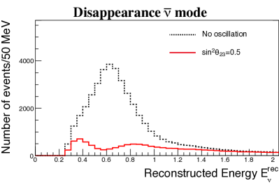
The reconstructed neutrino energy distributions of events for several values of are shown in the top plots of Fig. 133. The effect of is clearly seen using the reconstructed neutrino energy. The bottom plots show the difference of reconstructed energy spectrum from for the cases and . The error bars correspond to the statistical uncertainty. By using not only the total number of events but also the reconstructed energy distribution, the sensitivity to can be improved and one can discriminate all the values of , including the difference between and for which CP symmetry is conserved.
Figure 134 shows the reconstructed neutrino energy distributions of the sample, for the cases with and without oscillation. Thanks to the narrow energy spectrum tuned to the oscillation maximum with off-axis beam, the effect of oscillation is clearly visible.
III.1.1.5 Analysis method
As described earlier, a binned likelihood analysis based on the reconstructed neutrino energy distribution is performed to extract the oscillation parameters. Both appearance and disappearance samples, in both neutrino and antineutrino mode data, are simultaneously fitted.
The used in this study is defined as
| (28) |
where is the log likelihood for a Poisson distribution,
| (29) |
Here, and are the number of events in -th reconstructed energy bin for the hypothesis and test oscillation parameters, respectively. The index runs over all reconstructed energy bins for muon and electron neutrino samples and for neutrino and anti-neutrino mode data. The parameters represent fractional variations of the bin entries due to systematic uncertainties.
The penalty term in Eq. 28 constrains the systematic parameters with the normalized covariance matrix ,
| (30) |
In order to reduce the number of the systematic parameters, several reconstructed energy bins that have similar covariance values are merged for .
A robust estimate of the uncertainties is possible based on the T2K experience. For each of three main categories of systematic uncertainties, we have made the following assumptions taking into account improvements expected with future T2K data and analysis improvements.
- i) Flux and cross section uncertainties constrained by the fit to near detector data
-
Data from near detectors will be used in conjunction with models for the neutrino beam, neutrino interactions, and the detector performance to improve our predictions of the flux at SK and some cross-section parameters. The understanding of the neutrino beam, interaction, and detector is expected to improve in the future, which will result in reduction of uncertainties in this category. On the other hand, the near detector analysis is expected to include more samples to reduce the uncertainty for category ii), which will result in migration of some errors into this category. This category of uncertainties is assumed to stay at the same level as currently estimated by T2K.
- ii) Cross section uncertainties not constrained by the fit to near detector data
-
This category of error stems from the cross-section parameters which are independent between the near and far detectors because of their different elemental composition and the cross-section parameters for which the near detector is insensitive. In T2K, an intensive effort has been made to include more samples into analysis, such as data from FGD2 containing a water target Abe et al. (2017c) and large scattering angle events, to provide more constraints on the cross section models. Further improvement is expected in future analysis as T2K accumulates and analyze more data. In addition, the intermediate detector will significantly reduce the uncertainty due to the neutrino interaction models.
- iii) Uncertainties on the far detector efficiency and reconstruction modeling
-
Because most of the uncertainties related to far detector performance are estimated by using atmospheric neutrinos as a control sample and the current error is limited by statistics, errors in this category are expected to decrease with much larger statistics available with Hyper-K than currently used for T2K. Uncertainties arising from the energy scale are kept the same because they are not estimated by the atmospheric neutrino sample, although it could be also reduced with a larger statistics control sample and better calibration of the detector.
Compared to the systematic uncertainty used for the past publication Abe et al. (2015d), the uncertainties for anti-neutrino beam mode have been reduced to a similar level as those for neutrino beam mode, based on the experience with T2K anti-neutrino oscillation analysis. The flux and cross section uncertainties are assumed to be uncorrelated between the neutrino and anti-neutrino data, except for the uncertainty of / cross section ratio which is treated to be anti-correlated considering the theoretical uncertainties studied in Day and McFarland (2012). Because some of the uncertainties, such as those from the cross section modeling or near detector systematics, are expected to be correlated and give more of a constraint, this is a conservative assumption. The far detector uncertainty is treated to be fully correlated between the neutrino and anti-neutrino data.
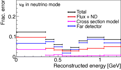
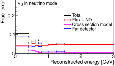
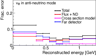
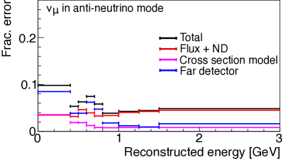
Figures 135 and 136 show the fractional and total systematic uncertainties for the appearance and disappearance reconstructed energy spectra in neutrino and anti-neutrino mode, respectively. Black lines represent the prior uncertainties and bin widths of the systematic parameters , while colored lines show the contribution from each uncertainty source. It should be noted that because some uncertainties are correlated between bins, the uncertainty on the total number of events is not a simple flux-weighted sum of these errors. For example, the energy scale uncertainty of the far detector has a large contribution around the flux peak, but it does not change the total number of events. Figure 137 shows the correlation matrix of the systematic uncertainties between the reconstructed neutrino energy bins of the four samples. The systematic uncertainties of the number of expected events at the far detector are summarized in Table 38.
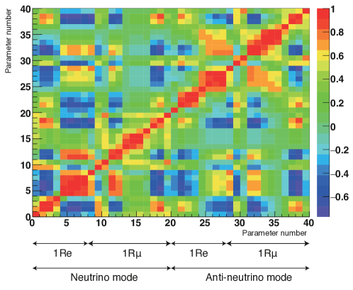
| Flux & ND-constrained | ND-independent | Far detector | Total | ||
|---|---|---|---|---|---|
| cross section | cross section | ||||
| mode | Appearance | 3.0% | 0.5% | 0.7% | 3.2% |
| Disappearance | 3.3% | 0.9% | 1.0% | 3.6% | |
| mode | Appearance | 3.2% | 1.5% | 1.5% | 3.9% |
| Disappearance | 3.3% | 0.9% | 1.1% | 3.6% |
III.1.1.6 Measurement of asymmetry
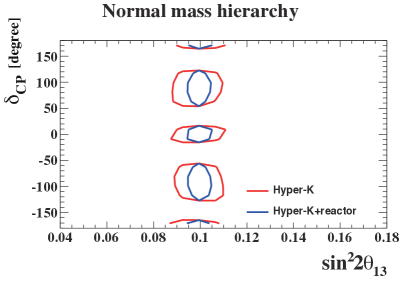
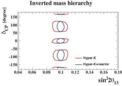
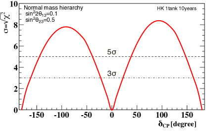
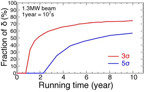
Figure 138 shows examples of the 90% CL allowed regions on the – plane resulting from the true values of . The left (right) plot shows the case for the normal (inverted) mass hierarchy. Also shown are the allowed regions when we include a constraint from the reactor experiments, . With reactor constraints, although the contour becomes narrower in the direction of , the sensitivity to does not significantly change because is constrained by the comparison of neutrino and anti-neutrino oscillation probabilities by Hyper-K and not limited by the uncertainty of .
Figure 139 shows the expected significance to exclude (the conserved case). The significance is calculated as , where is the difference of for the trial value of and for or 180∘ (the smaller value of difference is taken). We have also studied the case with a reactor constraint, but the result changes only slightly. Figure 140 shows the fraction of for which is excluded with more than 3 and 5 of significance as a function of the integrated beam power. The ratio of integrated beam power for the neutrino and anti-neutrino mode is fixed to 1:3. The normal mass hierarchy is assumed. The results for the inverted hierarchy are almost the same. violation in the lepton sector can be observed with more than 3(5) significance for 76(57)% of the possible values of .
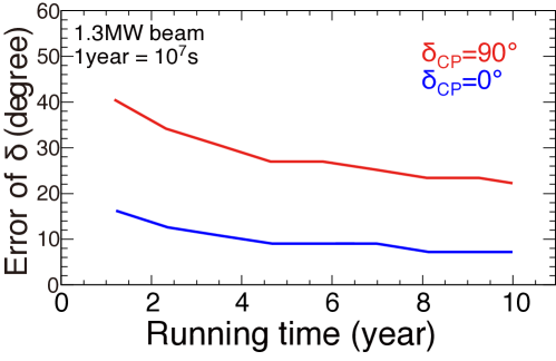
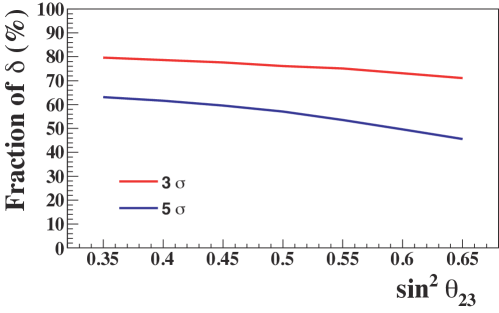
Figure 141 shows the 68% CL uncertainty of as a function of the integrated beam power. The value of can be determined with an uncertainty of 7.2∘ for or , and 23∘ for .
As the nominal value we use , but the sensitivity to violation depends on the value of . Figure 142 shows the fraction of for which is excluded with more than 3 and 5 of significance as a function of the true value of . T2K collaboration reported in case of the normal hierarchy Abe et al. (2017d).
| () exclusion | 68% uncertainty of | |||
| Configuration | ||||
| 1 tank | 76% | 57% | 7.2∘ | 23∘ |
| Staging | 78% | 62% | 7.2∘ | 21∘ |
| PTEP Abe et al. (2015d) | 76% | 58% | 7∘ | 19∘ |
Table 39 shows a comparison of several configurations for CP violation sensitivities.
III.1.1.7 Precise measurements of and
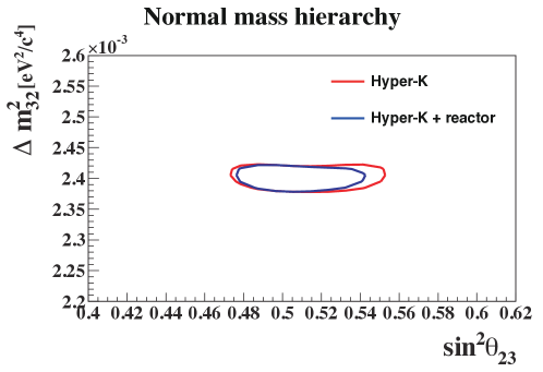
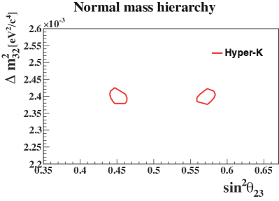
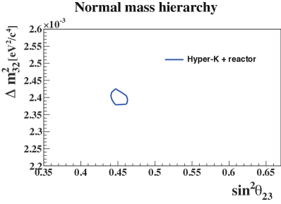
| True | ||||||
|---|---|---|---|---|---|---|
| Parameter | (eV2) | (eV2) | (eV2) | |||
| NH | 0.006 | 0.017 | 0.009 | |||
| IH | 0.006 | 0.017 | 0.009 | |||
A joint fit of the and samples enables us to also precisely measure and . Figure 143 shows the 90% CL allowed regions for the true value of . The expected precision of and for true with reactor constraint on is summarized in Table 40.
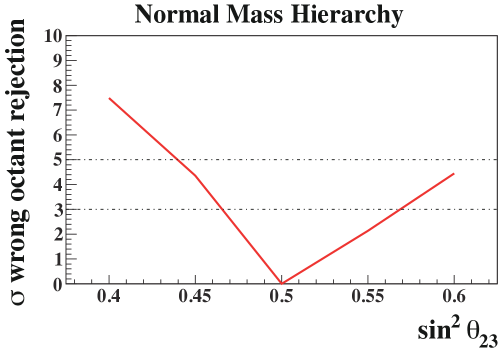
Figure 144 shows the 90% CL allowed regions on the – plane, for the true values of and eV2. With a constraint on from the reactor experiments, Hyper-K measurements can resolve the octant degeneracy and precisely determine . Figure 145 shows the expected significance for wrong octant rejection with beam neutrino measurement alone as a function of true value of in the normal hierarchy case.
As discussed earlier, a precision measurement of , compared with reactor measurements of , will enable a consistency check of the mixing matrix framework. The difference expected from the current knowledge of oscillation parameters is a few %. The uncertainty of by Hyper-K is expected to reach , while measurements by future reactor experiments are expected to achieve precision. Thus, the comparison will yield a significant consistency check.
III.1.1.8 Neutrino cross section measurements
With a set of highly capable neutrino detectors envisioned for Hyper-K project, a variety of neutrino interaction cross section measurements will become possible. The near detector suite offers a range of capabilities to probe different theoretical models for neutrino interactions: in particular data across different momenta ranges and a range of lepton emission angles. Figure 146 shows the efficiency of different detectors as a function of angle and muon momentum. The ability to measure exclusive hadronic final states, using techniques such as high pressure gas TPCs or emulsion detectors, provides valuable additional information for exclusive cross-sections. In table 41 we estimate the sensitivity of each proposed near detector for key selections based on a flux of POT.
| Detector | Selection | Nevents | Selection Characteristics |
| ND280 detector, 280m | CC0 | 20k | FGD1 (1–3 GeV), 72% Abe et al. (2015c) |
| ND280 detector, 280m | CC1 | 6k | FGD1 (1–3 GeV), 50% Abe et al. (2015c) |
| ND280 detector, 280m | CC inclusive | 40k | FGD1 (1–3 GeV), 90%Abe et al. (2015c) |
| INGRID | CC inclusive | 17.6 | 70% (1–3 GeV), 97% Abe et al. (2015f) |
| HPTPC, 8 m3, 10 bar Ne (CF4) | CC inclusive | 4.2k (18.4k) | 70%, protons 5 MeV detected |
| HPTPC, 8 m3, 10 bar Ne (CF4) | CC inclusive | 80 (450) | 70%, protons 5 MeV detected |
| WAGASCI | CC0 | 63k | P=75%, proton reconstruction: % at p=500 MeV/c, water in; % at p=250 MeV/c, water out (15% @ 150MeV/c) |
| WAGASCI | CC1 | 10k | P=50% (protons as above) |
| WAGASCI | CC inclusive | 75k | P=96% (protons as above) |
| 200kg Water target | CC+NC inclusive | 10k-20k | 4 automated readout |
| emulsion off-axis, 280m | proton 10-30 MeV detected | ||
| 200kg Water target | CC inclusive | 1k | 4 automated readout |
| emulsion off-axis, 280m | proton 10-30 MeV detected | ||
| 1kton WC 1 km | CC0 (1-2∘,2-3∘,3-4∘) | 1682k,1060k,519k | 92%,95%,95% |
| 1kton WC 1 km | CC0 (1-2∘,2-3∘,3-4∘) | 519k,331k,186k | 74%,77%,76% |
| 1kton WC 1 km | CC1 (1-2∘,2-3∘,3-4∘) | 208k,65k,27k | 46%,44%,31% |
| 1kton WC 1 km | CC0 (1-2∘,2-3∘,3-4∘) | 11.2k,6.9k,4.6k | 54%,71%,80% |
| 1kton WC 1 km | NC (1-2∘,2-3∘,3-4∘) | 300k,111k,45k | 58%,63%,60% |
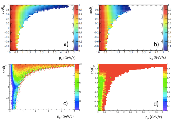
III.1.1.9 Searches for new physics
In addition to the study of standard neutrino oscillation, the combination of intense beam and high performance detectors enables us to search for new physics in various ways. Examples of possible searches for new physics with Hyper-K and accelerator beam are listed below.
III.1.1.9.1 Search for sterile neutrinos
Sterile neutrinos can be searched for in both disappearance and appearance channels in near and intermediate detectors. With neutrino energy of 0.1–few GeV and baseline of 0.3 km and 1–2 km, it will be sensitive to of eV2, which is the interesting region in light of several anomalies reported by recent experiments. T2K has searched for sterile neutrino in appearance and disappearance with near detectors Abe et al. (2015g); Dewhurst (2015). With more statistics, improved detectors, and possible two detector configuration with near and intermediate detectors, Hyper-K near detectors will have chance to improve the sensitivity for sterile neutrino searches.
Neutral current measurements at the far detector will be also sensitive to the sterile neutrino, because the neutral current channel measures the total active flavor content. By selecting two electron-like ring events with no decay electron and invariant mass consistent with , neutral current events with 96% purity can be obtained. With protons on target and 560 kton fiducial mass, more than 4,000 NC events are expected after selection. Normalization of the NC production can be strongly constrained by the high statistics data at the intermediate detector as shown in Table 41.
III.1.1.9.2 Test of Lorentz and CPT invariance
Lorentz Violation arises when the behavior of a particle depends on its direction or boost velocity and is predicted to occur at the Planck scale (1019 GeV). Searches for Lorentz Violation have been performed by various experiments, including T2K, by looking for a sidereal time dependence of the neutrino event rate. Similar searches can be carried out with larger statistics and improved detectors.
III.1.1.9.3 Heavy neutrino search
The existence of heavy neutral leptons (heavy neutrinos) is predicted in many extensions of the Standard Model. Such heavy neutrinos may be produced in decays of kaons and pions from the target. Then, decays of heavy neutrinos can be detected in the near detector. The feasibility of search for heavy neutrinos in accelerator neutrino experiment, in particular with T2K, is studied in Asaka et al. (2013) and the sensitivity is expected to be better than previous searches. Because interactions of ordinary neutrinos produce background to this search, having a low density detector such as a gas TPC inside a magnetic field like ND280 is an advantage for this search. The sensitivity will be further enhanced if a larger volume of gas detector is employed.
III.1.1.10 Summary
The sensitivity to leptonic asymmetry of a long baseline experiment using a neutrino beam directed from J-PARC to the Hyper-Kamiokande detector has been studied based on a full simulation of beamline and detector. With 108 sec of running time with 1.3 MW beam power, the value of can be determined with 7.2∘ for or , and 23∘ for . violation in the lepton sector can be observed with more than 3 (5 ) significance for 76%(57%) of the possible values of . Using both appearance and disappearance data, precise measurements of and will be possible. The expected 1 uncertainty of is 0.017 (0.006) for . The uncertainty of is expected to reach .
There will be also a variety of measurements possible with both near and far detectors, such as neutrino-nucleus interaction cross section measurements and search for exotic physics, using the well-understood neutrino beam.
III.1.2 Atmospheric neutrinos
Primary cosmic ray interactions with nuclei in the atmosphere produce charged hadrons whose decays further create a continuous flux of neutrinos known as atmospheric neutrinos. Since the primary cosmic ray flux is known to be nearly isotropic about the earth, the resulting neutrino flux is present at all zenith angles observed by a terrestrial detector. Further, these neutrinos are less energetic than their cosmic ray parents by roughly an order of magnitude meaning that the range of available neutrino energies for observation spans several orders of magnitude starting near O(100) MeV. This diversity of both energy and pathlength, which ranges from O(10) to O() km, makes atmospheric neutrinos a particularly versatile tool for studying neutrino oscillations. However, these neutrinos represent the most serious background to nucleon decay searches (discussed in Section III.2.1). At the same time they form the basis for searches for exotic particles, such as dark matter (discussed in Section III.3.2), whose interactions may produce neutrinos that would subsequently appear atop the atmospheric neutrino spectrum. For these reasons a precise characterization of the atmospheric neutrino flux is key to future discoveries at Hyper-Kamiokande.
Though atmospheric neutrinos were used to make the first discovery of the neutrino oscillation phenomenon, for very large detectors like Hyper-Kamiokande, they provide excellent sensitivity to many of the remaining open questions in oscillation physics. Indeed, current neutrino telescopes have demonstrated constraints on the atmospheric mixing parameters comparable to beam measurements using atmospheric neutrinos alone. Additionally, future experiments seek to use these neutrinos to study the mass hierarchy. While both of these measurements and more are available to Hyper-Kamiokande, it offers two distinct advantages over current and planned projects. First, with its exquisite ability to distinguish between charged current and interactions, it will have improved access to the oscillation modes with the most hierarchy sensitivity, and . It is indeed the asymmetry in these two probabilities for few GeV neutrinos traversing the earth that provides the cleanest signature of the mass hierarchy. Additionally, Hyper-Kamiokande will make combined beam and atmospheric neutrino oscillation measurements to yield increased sensitivity. Details of Hyper-K’s physics potential using atmospheric neutrinos by themselves and in conjunction with beam neutrinos are presented in the next two subsections.
III.1.2.1 Neutrino oscillation studies (MH, octant, phase)
As atmospheric neutrinos span both low and high energies as well as long and short path lengths, they are in principal sensitive to all parameters in the PMNS mixing paradigm. That being said, the most apparent oscillation features are driven by the so-called atmospheric mixing parameters, and , and they induce a deficit of observed upward-going interactions at predominantly multi-GeV energies as these neutrinos oscillate into primarily unobserved . However, now that the value of is known to be non-zero the presence of matter effects on atmospheric neutrinos that traverse the earth makes important contributions to this picture. Matter-induced parametric oscillations in the energy range 2-10 GeV lead to significant enhancement of either the or the appearance probability for upward-going neutrinos depending upon the mass hierarchy. For the normal (inverted) hierarchy neutrino (antinuetrino) oscillations are enhanced. This enhancement leads to appearance probabilities around 50% for both hierarhies. The separation of atmospheric neutrino data into neutrino-like and antineutrino-like subsets can therefore be used to extract the hierarchy signal. Importantly, the features of these oscillations are also a strong function of and, to a lesser extent, the value of . It should be noted that these matter effects affect both the appearance and disappearance, , channels, enabling mass hierarchy sensitivity in both the -like and -like data at Hyper-K.
Including these effects the flux of atmospheric at the detector may be written roughly as,
| (31) | |||||
where these three terms are identified as the “solar”, “interference,” and “parametric (resonance)” terms, respectively. Here is the two neutrino oscillation probability driven by the solar mass splitting . Note that the effect of appears in the interference term, which is controlled by an effective mixing angle in matter, , and where and denote amplitudes for CP-even and CP-odd oscillations. Antineutrino oscillations are described by changes to these amplitudes under an inversion of the sign of both the matter potential and of . At sub-GeV energies the flux ratio , , is , and increases above 1 GeV until reaching at 10 GeV.
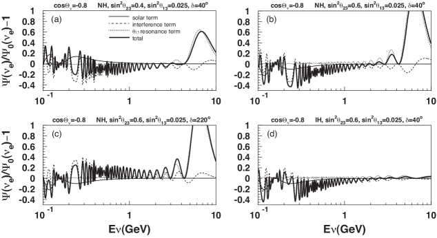
Figure 147 shows the expected flux at the detector normalized to the unoscillated prediction under this approximation for four configurations of the oscillation parameters and neutrinos with . At energies between 5-10 GeV the most prominent feature of the figure is the parametric resonance driven by , whose amplitude increases with ( c.f. panels a. and b.). Further, this resonance becomes suppressed in the neutrino channel when the hierarchy is switched from normal to inverted (compare panels a. and d.). Though some change in the resonance can be seen via the interference term as is varied, the dominant effect appears below 1 GeV (panels a. and c.). For these reasons the atmospheric neutrino oscillation analysis has been designed to maximize each of these potential effects.
Hyper-Kamiokande’s reconstruction performance is expected to meet or exceed that of its predecessor, Super-Kamiokande. Nominally the size and configuration of the two detectors are similar enough that event selections and systematic errors are not expected to differ largely. While the larger statistics afforded by Hyper-K may result in improved detector systematic uncertainties, such improvements are not assumed here. Similarly, improvements in the uncertainty of the atmospheric neutrino flux, the leading systematic for studies of with atmospheric neutrinos, or the cross section model, which largely affects the mass hierarchy sensitivity, are not assumed in the studies below. The analyses proceed following those at Super-K using simulation and reconstruction tools tuned and validated for that experiment.
Atmospheric neutrino MC corresponding to a 75 year exposure of the 186 kton Hyper-K detector has been generated based on the flux model presented in Honda et al. (2007) and using the NEUT interaction generator. The analysis is based on 19 samples optimized for sensitivity to potential oscillation signals at both high (multi-GeV) and low (sub-GeV) energies. Interactions are divided into sub-samples based upon the particle ID of their most energetic reconstructed Cherenkov ring (-like or -like) and the number of such rings. Additional selections are made to the multi-GeV -like samples to separate them into antineutrino-like and neutrino-like subsamples Pik (2012). Event topologies with particles exiting the inner detector and depositing light in the outer veto as well as muons from neutrino interactions in the rock surrounding the detector are also included in the analysis. Further details of the sample selection are presented elsewhere Abe et al. (2015a). Zenith angle distributions for six of the analysis samples are shown for both assumptions in figure 148.
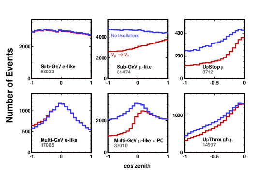
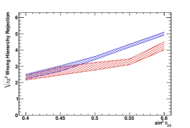
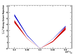
Figure 149 shows the Hyper-K’s expected sensitivity to resolving the neutrino mass hierarchy and the octant of assuming a single detectors after 10 years. Both panels of the figure are shown as a function of the true value of for the range of values allowed by recent measurements from the T2K experiment Abe et al. (2015c) and the width of the bands in the figures illustrates the uncertainty from . In each panel the sensitivity is defined as , which for mass hierarchy resolution corresponds to , where and refer to the true hierarchy and the alternate hierarchy hypotheses, respectively. The octant sensitivity is defined similarly. After 10 years (a 1.9 Mtonyear exposure) Hyper-K is expected to resolve the mass hierarchy at for both hierarchy assumptions and when . Similarly the atmospheric neutrino data alone can be used to determine the octant at when Note further that atmospheric neutrinos can be used to measure the chemical composition of the Earth’s interior. Details of Hyper-K’s expected sensitivity are presented in section III.3.4.
III.1.2.2 Combination with Beam Neutrinos
Hyper-K will have improved sensitivity to neutrino oscillations by joint analysis of its atmospheric and accelerator (long-baseline beam) neutrino data sets. A particularly striking example comes in the form of mass hierarchy resolution. Since matter effects are small for the 295 km baseline Tokai-to-HK baseline, the beam neutrino data will have limited sensitivity to the mass hierarchy. At the same time, though matter effects are strong in the resonance-enhanced oscillation region of the atmospheric neutrino energy spectrum, lacking precise knowledge of these neutrinos’ true baseline limits their ability to constrain the atmospheric neutrino mixing parameters which govern the size of the expected enhancement namely, . Further, approximate degeneracies between this parameter and the sign of weaken the mass hierarchy sensitivity. Note, for instance, the dramatic influence has on Hyper-K’s atmospheric neutrino-only sensitivity in Figure 149. The off-axis angle of the beam measurement, on the other hand, provides a clean measurement of the atmospheric mixing parameters and therefore provides for a precise prediction of the expected amount of appearance expected in the resonance region. Fitting the two data sets together in turn improves the overall mass hierarchy sensitivity. Figure 150 shows the evolution of the combined sensitivity over time. With five years of data with the 1TankHD detector the combined atmospheric neutrino and beam samples show better than ability to reject the incorrect mass hierarchy, assuming either the normal or inverted hierarchy is true. Similarly, the ability to resolve the octant improves with the combination as shown in Figure 151. While atmospheric neutrinos alone can resolve the octant at 3 if in the combined analysis it can be resolved when this difference is only in ten years.
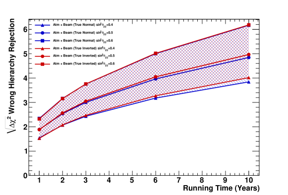
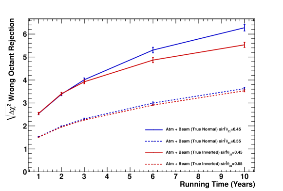
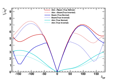
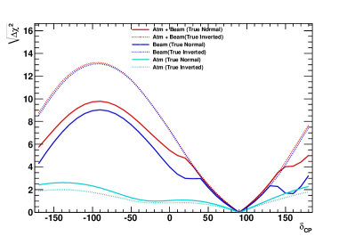
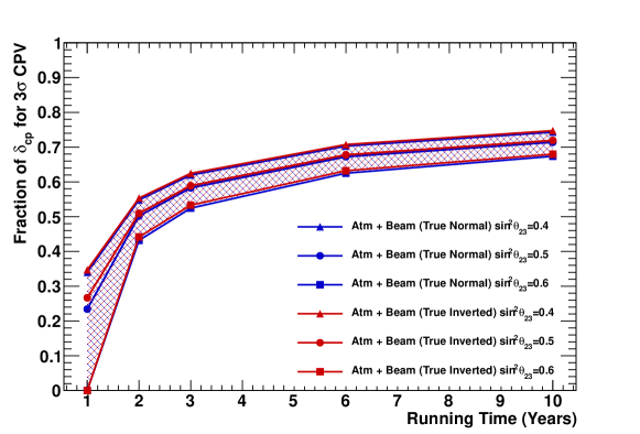
However, it is not just the atmospheric neutrinos that benefit from combined measurements. Indeed, for a fixed baseline uncertainty in the mass hierarchy leads to parameter degeneracies in the the beam neutrino measurement of . The atmospheric neutrino data, on the other hand, can be used not only to resolve the mass hierarchy and subsequently these degeneracies, but they also provide complementary sensitivity to . The left panel of Figure 152 shows the expected constraint on this parameter assuming its true value is for separate beam and atmospheric neutrino measurements. While the beam measurement (gray) shows excellent precision near the true parameter value, there is a strong degeneracy near when the mass hierarchy is unknown. This false solution is not present in the atmospheric neutrino measurement (blue), so the combination of the two (red) measurements yields a very precise measurement. The situation is similar in the right panel, which shows the sensitivity when Hyper-K’s ability observe CP violation at or better is shown as a function of time for the combined measurement in Figure 153. Table 42 summarizes Hyper-K’s expected sensitivity to various parameters when using atmospheric neutrinos only and when combining them with the beam data.
| Metric | 1TankHD | ||
|---|---|---|---|
| Atmospheric | Atm Beam | ||
| Hierarchy | 2.2 | 3.8 | |
| 4.9 | 6.2 | ||
| Octant | 2.2 | 6.2 | |
| 1.6 | 3.6 | ||
III.1.2.3 Exotic Oscillations And Other Topics
Though the standard paradigm of neutrino oscillations driven by two mass differences has been well established, hints for a third mass difference with have been seen in a variety of short-baseline experiments (c.f. Aguilar-Arevalo et al. (2001, 2013); Huber (2011); Mention et al. (2011)). Measurements of the decay width, however, indicate that there are only three neutrinos that participate in the weak interaction and therefore explaining the short-baseline data with an additional neutrino means it cannot couple to the and therefore cannot participate in ordinary weak interactions. Such a state is referred to as “sterile.” Even without weak interactions the existence of such sterile neutrinos can make imprints on the atmospheric neutrino spectrum visible at Hyper-K. In addition to sterile neutrinos, other sub-dominant contributions to the standard oscillation picture, such as effects of Lorentz-invariance violating (LV) processes are expected to influence the oscillations of atmospheric neutrinos. Positive observation of LV would provide access to physics at the Planck scale, an energy regime far beyond the reach of current accelerator technology. Though Hyper-K will have an atmospheric neutrino sample of unprecedented size, its increased sensitivity to sterile and LV oscillations relative to existing measurements is hampered by our current understanding of atmospheric neutrino flux and interaction uncertainties. In particular, reductions in the uncertainty on the absolute neutrino flux, the ratio below 10 GeV, and the cross section ratio will improve Hyper-K’s sensitivity to these oscillations.
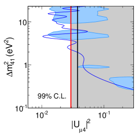
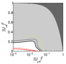
Extensions of the standard (PMNS) oscillation framework to include sterile states expand the mixing matrix with additional rows and columns that include terms describing mixing between the active and sterile neutrinos, such as , , and Interestingly, for mass differences , as suggested by short-baseline measurements, atmospheric neutrinos are not sensitive to the exact value of the splitting and further, they are essentially insensitive to the exact number of sterile neutrinos. Nonetheless, non-zero mixing of the active and sterile neutrinos is expected to produce spectral distortions of the atmospheric neutrino flux or suppress it. Sterile neutrinos lack NC interactions, which makes them subject to an additional effective potential, when traveling through matter. Here, is the local neutron density and the Fermi constant.
Due to the complications of simultaneously describing sterile matter effects and oscillations that include for atmospheric neutrinos two searches for sterile neutrinos are performed following the formalism of Maltoni and Schwetz (2007). For the first analysis both and are set to zero, decoupling oscillations from the other active neutrinos. In so doing, atmospheric neutrinos are sensitive to the effects of , which is expected to decrease the overall survival probability, and , which causes an energy dependent distortion of the flux through the sterile matter potential. However, this comes at the expense of a slight bias in the measurement of . Constraints on are possible via its effect on the partially contained (PC) and upward-going (Up )samples, both of which are enriched in interactions. In the second analysis, sterile matter effects are assumed to be negligible and oscillations are reintroduced. This approximation allows for an unbiased measure of . The results of these analyses are shown in comparison to limits from Super-K are shown in Figure 154. It should be noted that the relatively modest improvement in Hyper-K’s measurement of is due to uncertainties in the flux and CCQE cross section below 10 GeV.
| Analysis | [GeV] | |||||
|---|---|---|---|---|---|---|
| Super-K | ||||||
| Hyper-K | ||||||
Atmospheric neutrino oscillations are particularly sensitive to effects of LV processes due to their interferometric nature. Though such effects may manifest in atmospheric neutrinos as either sidereal variations in their oscillations or as distortions in the oscillated spectra, the present analysis considers only the latter. The search is performed within the context of an effective field theory which contains the standard model, general relativity, and all possible LV operators known as the standard model extension (SME) Kostelecky (2004). Much like the sterile oscillations described above the SME extends neutrino Hamiltonian by introducing a LV component,
| (38) |
where and are complex coefficients for isotropic LV operators. In general the parameters produce oscillation effects proportional to the neutrino propagation distance, , while the induce effects that depend on , where is the neutrino energy. While atmospheric neutrinos are effective probes of such exotic oscillations due to their the large variety of pathlengths and energies, this same feature prohibits perturbative solutions to SME Hamiltonian and instead the problem must be fully diagonalized.
Event modest amounts of LV can have large effects on atmospheric neutrino oscillations, but generally they are expected to appear primarily in the multi-GeV (both -like and -like), PC, and Up samples. Both the real and imaginary components of each of the LV coefficients found in the Hamiltonian above are then fit for in the analysis, with each coefficient considered individually while all others are held at zero. Limits from a 5.6 Mtonyear exposure of Hyper-K within this framework appear in conjunction with limits from Super-K in Table 43. For each of the considered coefficients the expected Hyper-K limit is roughly three or four times more stringent. Additional sensitivity may be gained by incorporating more detailed shape information into the Hyper-K analysis through finer binning.
In addition to the studies presented above, Hyper-K’s atmospheric neutrino sample is expected to enable measurements of several other physical phenomena, including the CC cross section, non-standard neutrino interactions, the primary atmospheric neutrino flux, and others. The study of interactions is a topic of particular importance, since oscillation-induced events within the detector are often reconstructed as multi-GeV e-like interactions in the upward-going direction making them a significant background to Hyper-K’s mass hierarchy sensitivity. In addition, since creating and subsequently observing in accelerator experiments is difficult the world data is comprised of only a handful of events (nine events from DONuT Kodama et al. (2008), and five from OPERA Agafonova et al. (2015)). For this reason the uncertainty in the interaction cross section is large, with reference Abe et al. (2015a) assigning a 25% systematic error based on a survey of theoretical models. Super-Kamiokande has developed a method to extract oscillation-induced events from the atmospheric neutrino background based on a neural network procedure trained to select CC interactions in which the lepton has decayed hadronically. This technique was used to successfully identify an oscillation-induced signal of events atop of a background of events per 100 kton years Abe et al. (2013c). Extrapolating to a 10 year exposure of Hyper-K, this would correspond to more than 700 CC interactions. Further, by incorporating the neural network variable into the oscillation analysis described in Section III.1.2 it is possible to isolate the -like events and use them to measure their cross section normalization. Hyper-K’s expected sensitivity to this normalization is shown in Figure 155.
III.1.3 Solar neutrinos
The solar neutrino measurements are capable of determining the neutrino oscillation parameters between mass eigenstate and in the equation (14). Figure 156 shows the latest combined results of the allowed neutrino oscillation parameters, and from all the solar neutrino experiments, as well as the reactor neutrino experiment KamLAND Koshio (2015). The mixing angle is consistent between solar and reactor neutrinos, while there is about 2 tension in . This mainly comes from the recent result of the solar neutrino day-night asymmetry and energy spectrum shape observed in Super-K. In solar neutrino oscillations, regeneration of the electron neutrinos through the MSW matter effect in the Earth is expected. According to the MSW model, the observed solar neutrino event rate in water Cherenkov detectors in the nighttime is expected to be higher – by about a few percent in the current solar neutrino oscillation parameter region – than that in the daytime as shown in the Figure 156. Super-K found the first indication of this day-night flux asymmetry at the 3 level Renshaw et al. (2014), but conclusive evidence is expected in Hyper-K. If the 2 tension of between solar () and reactor () neutrinos is a real effect, new physics must be introduced.
In addition to that, the observation of the upturn in the solar neutrino survival probability might be possible. The spectrum upturn is produced by the transition of the survival probability in from the matter dominant energy region to the vacuum dominant energy region in the solar neutrino oscillation, and has been observed by the comparison between 8B solar neutrino flux in Super-K and SNO and 7Be solar neutrino flux in BOREXINO Bellini et al. (2011). However, the precise measurement of the spectrum shape can distinguish the usual neutrino oscillation scenario from several exotic models such as non standard interaction Friendland (2004), MaVaN Barger (2005), and sterile neutrino Holand and Smirnov (2004), for example. Due to the high photo-coverage of 40 %, the lower energy threshold required to measure the upturn is possible because of better energy resolution and reduction of the radio active background. 666 Though the energy of the radioactive events are lower than the energy threshold, they can be misreconstructed such that they contaminate the region above the energy threshold. If the energy resolution is better, the background will be reduced more. See more in Section II.4.1.
In the following sections, the sensitivity of the day-night flux asymmetry and spectrum upturn in Hyper-K are described.
Hyper-K also could be used for variability analyses of the Sun. For example, the 8B solar neutrino flux highly depends on the Sun’s present core temperature Bahcall and Ulmer (1996). Unlike multiply scattered, random-walking photons or slow-moving helioseismic waves, free streaming solar neutrinos are the only available messengers with which to precisely investigate ongoing conditions in the core region of the Sun. Hyper-K, with its unprecedented statistical power, could measure the solar neutrino flux over short time periods. Therefore, short time variability of the temperature in the solar core could be monitored by the solar neutrinos in Hyper-K.
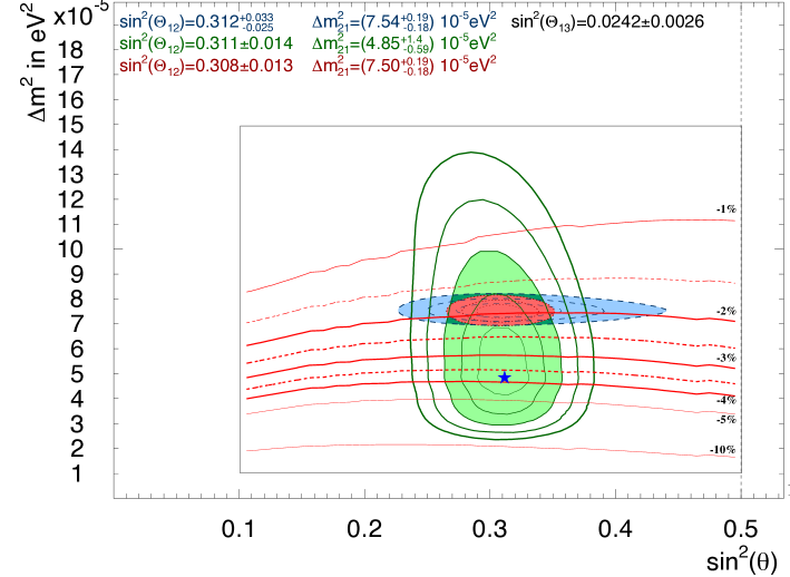
III.1.3.1 Background estimation
The major background sources for the 8B solar neutrino measurements are the radioactive spallation products created by cosmic-ray muons Zhang et al. (2016) and the radioactive daughter isotopes of in water. The spallation products is discussed in detail in the paragraph II.4.1.3.2, and the rate of spallation which result in relevant backgrounds is 2.7 times higher in Hyper-K compared to Super-K because of its shallow depth. As the radioactive daughter isotopes, is an important background source for the spectrum upturn measurement. First of all, the water purification system must achieve levels similar to that achieved at Super-K. Furthermore, this background level must be achieved across the full fiducial volume, unlike at Super-K, where only a limited volume can be used for events with less than 5 MeV of energy. It is a challenging task but we believe that this should be possible by design improvements over the next several years. Therefore, the same background level as Super-K in full fiducial volume is assumed in the following calculation.
III.1.3.2 Oscillation studies
In order to calculate the neutrino oscillation sensitivity, the signal and background rates in each option have to be estimated. As for the day-night asymmetry analysis, the energy threshold is set to 6.5 MeV (in kinetic energy) since its effect is larger at higher energy region. In this energy region, only spallation backgrounds should be considered. The remaining spallation background rate in Super-K phase IV (40% photo-coverage) has been reduced by a factor three comparing to Super-K phase II (20% photo-coverage) because of the better energy resolution and better vertex resolution. From this experience in Super-K, the spallation background in Hyper-K will be reduced by a factor three because of the higher photon detection efficiency than Super-K.
Figure 157 shows the sensitivity of the day-night asymmetry as a function of the observation time. The separation ability between solar neutrino (HK) and reactor anti-electron neutrino (KamLAND) is expected 45 level in ten years observation, though it depends on the systematic uncertainty.
In the measurement of the spectrum upturn, the background is critical because the 214Bi beta decay events (3.27 MeV end point energy) will come above the energy threshold due to the energy resolution. The Hyper-K detector, which has better energy resolution because of the higher photon detection efficiency than Super-K, is strong to reduce such kind of radioactive background. Furthermore, the precise energy calibration has to be considered. Here, it is assumed that the same background level with full fiducial volume and the same precision of the energy calibration as Super-K are achieved in Hyper-K. Figure 158 shows the sensitivity of the spectrum upturn discovery as a function of the observation time. It is about 3 level in ten years observation with 4.5 MeV energy threshold.
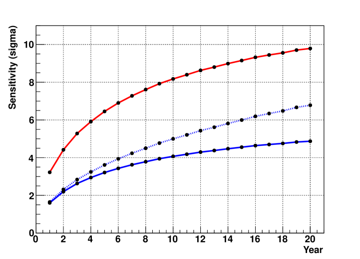
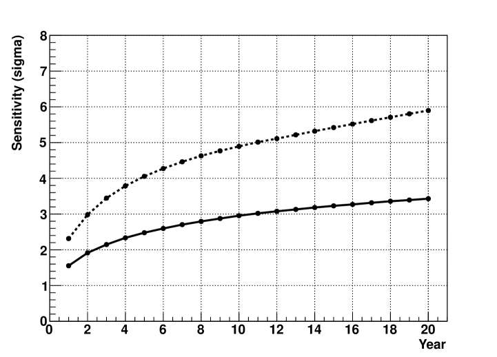
III.1.3.3 Hep solar neutrino
Hep solar neutrino produced by the 3He + fusion reaction has the highest energy in solar neutrinos. But, most of the hep energy spectrum is overlapped with 8B solar neutrinos. The expected 8B solar neutrino flux is more than 100 times larger than that of hep solar neutrino in Standard Solar Model (SSM). So far, only upper limits were reported from SNO and SK group Aharmin et al. (2006); Hosaka et al. (2006), but a recent improved analysis of the SNO charged-current data shows hints of a hep solar neutrino signal Winchester (2016), and indicates a higher hep flux than the SSM prediction.
The measurement of the hep solar neutrino could provide new information on solar physics. The production regions of the 8B and hep neutrinos are different in the Sun. The energy production peak of hep neutrinos is located at the outermost radius in the solar core region among all the solar neutrinos in pp-chain Bahcall (1989). So, they could be used as a new probe of the solar interior around core region. Non-standard solar models, originally motivated by the solar neutrino problem, predict the potential enhancement of the hep neutrino flux Bahcall and Ulrich (1988). This is realized through the mixing of 3He into the inner core on a time scale shorter than the 3He burning time. Significant mixing is already ruled out by helioseismology, however, the hep neutrino observation can be a sensitive probe of the degree of the mixing in the solar core. There is also the solar abundance problem. 8B and hep solar neutrino fluxes show different behavior with GS98 and AGSS09 chemical compositions Serenelli et al. (2011). Theoretical calculation of hep solar neutrinos is a difficult challenge Adelberger et al. (2011). The measurement of the hep solar neutrino flux will provide a better understanding of SSM. Hep solar neutrinos could be also used to test non-standard neutrino physics in the energy range ( MeV) Kubodera and Park (2004).
In Hyper-K, a high sensitivity measurements of hep solar neutrino flux would be possible, since the detector has a good energy resolution. Figure 159 shows the expected solar neutrino fluxes in 1.9 Mton year in Hyper-K detector.
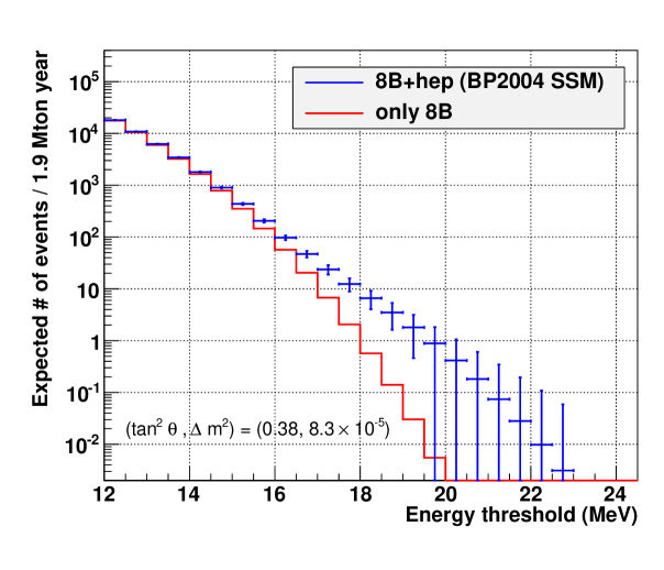
The separation between 8B and hep solar neutrinos highly depends on the energy resolution of the detector. Table 44 shows a list of expected numbers of solar neutrino events in typical energy regions.
| Energy resolution | Energy range | 8B | hep | hep / 8B |
|---|---|---|---|---|
| [MeV] | [/1.9 Mton/year] | [/1.9 Mton/year] | ||
| SK-III/IV | 19.5–25.0 | 0.77 | 3.03 | 3.9 |
| Hyper-K | 18.0–25.0 | 0.56 | 6.04 | 10.6 |
Hyper-K has a better separation between hep and 8B solar neutrinos comparing to SK-III/IV.
Figure 160 shows an estimation of hep neutrino detection sensitivity. A spectrum fit analysis is performed here, considering the spallation background, detection efficiency and systematic uncertainties of the energy scale and resolution. The statistical error due to remaining spallation background is the dominant source of ambiguity. When we simply scale the current remaining spallation background level in SK-IV solar analysis, with the cosmic muon rate at Tochibora, the uncertainty of the hep neutrino flux will be 60% (40%) and the non-zero significance will be 1.8 (2.3) in ten (twenty) years observation in Hyper-K. Due to the higher energy resolution of Hyper-K, there is still chance to improve the sensitivity. If we can reduce the remaining spallation background to the SK-IV level, the uncertainty of hep neutrino flux will be 40% (30%) and non-zero significance will be improved to 2.5 (3.2) in ten (twenty) years observation. Here the same systematic uncertainties of detector energy scale (0.5 %) and resolution (0.6 %) as SK-IV are considered.
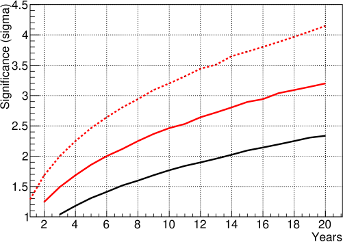
III.1.3.4 Summary
In this section, estimates of potential solar neutrino measurements are reported. The solar neutrino analysis is sensitive to the detector resolutions and background levels. We have estimated expected sensitivities in 10 years of Hyper-K observation based on the current Super-K knowledge.
As a result of its shallower site, the increase of the spallation background level in Hyper-K will be up to a factor of 2.7 larger as compared to Super-K. However – due to its much greater size and high energy resolution– the statistical uncertainties on solar neutrino measurements would actually be reduced in Hyper-K as compared to Super-K on an equal time basis.
The sensitivity to the difference in neutrino oscillation parameters between solar and reactor neutrinos due to the day-night asymmetry is estimated to be 45. The possibility of spectrum upturn observation is estimated to be at the 3 level.
The solar hep neutrino could be measured in Hyper-K with a few Mton year data at the level of .
III.2 Nucleon Decays
III.2.1 Nucleon decays
Optimizing Hyper-Kamiokande for the observation and discovery of a nucleon decay signal is one if its primary design drivers. In order to significantly extend sensitivity beyond existing limits, many of which have been set by Super-Kamiokande, Hyper-K needs both a much larger number of nucleons than its predecessor and sufficient reconstruction ability to extract signals and suppress backgrounds. While it is possible to target specific decay channels, one of the strengths of water Cherenkov technology is its sensitivity to a wide variety of modes. Using MC and analysis techniques originally developed for Super-Kamiokande, this section details Hyper-K’s expected sensitivity to both the flagship proton decay modes, and , as well as other conserving, dinucleon, and decays.
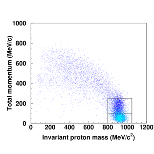
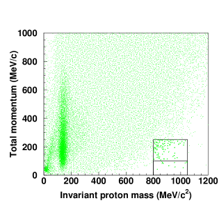
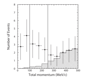

III.2.1.1 Sensitivity to Decay
Proton decay into a positron and neutral pion is a favored mode of many GUT models. Experimentally this decay has a very clean event topology, with no invisible particles in the final state. As a result it is possible fully reconstruct the proton’s mass from its decay products and as a two body process the total momentum of the recoiling system should be small. The event selection focuses on identifying fully contained events within the Hyper-K fiducial volume with two or three electron-like Cherenkov rings. Though the decay of the pion is expected to produce two visible gamma rays, for forward-boosted decays the two photons may be close enough in space to be reconstructed as a single ring. Atmospheric neutrino events with a muon below threshold are removed by requiring there are no Michel electrons in the event. For those events with three rings, the two rings whose invariant mass is closest to the mass are labeled the candidate. An additional cut on the mass of those candidates, MeV/, is applied. The signal sample is selected by requiring the total invariant mass of the event be near the proton mass, MeV/ and that the total momentum, , be less than 250 MeV/. Water is an excellent molecule for studying proton decay because in addition to providing 10 protons per molecule, two of those are unbound free protons. Decays from those protons are not subject to nuclear effects and result in final state particles with very low total momentum. At the same time, very few atmospheric neutrino interactions are reconstructed with both a proton-like invariant mass and low total momentum. To optimize the analysis sensitivity, proton-decay candidates are divided into two signal regions after the invariant mass cut, a free proton decay enriched region ( MeV/) and a bound proton decay region ( MeV/). Finally, neutron tagging (described in a later section) is used to reject background events by requiring events have no neutron candidates in the final state. Figure 161 shows the signal and background MC in the invariant mass and total momentum plane before the final signal region is defined. Signal efficiencies and background rates with corresponding systematic errors after all selections are listed in Table 45.
| MeV/ | MeV/ | ||
|---|---|---|---|
| [%] | Bkg [/Mtonyr] | [%] | Bkg [/Mtonyr] |
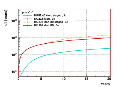
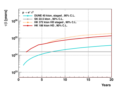
Monte Carlo simulation of these decays includes the effects of the nucleon binding energy, Fermi motion, and interactions within the nucleus. The latter represents a significant, but unavoidable, source of inefficiency as the signal may be lost to absorption or charge exchange prior to exiting the nucleus. Although the signal efficiency of free proton decays is roughly 87% these nuclear effects reduce the efficiency of bound proton decays such that the overall efficiency is only 40% when all decays are considered.
Atmospheric neutrino interactions are the main background to proton decay searches. Not only can CC single-pion production processes produce the same event topology expected in the decay, but recoiling nucleons from quasi-elastic processes can produce pion final states through hadronic scatters that mimic the signal. After the event selection above the expected background rate is 0.06 events in the free proton enhanced bin and 0.62 events in the bound proton enhanced bin per Mtonyear. These background expectations have been experimentally verified using beam neutrino measurements with the K2K experiment’s one kiloton water Cherenkov detector, which found an expected atmospheric neutrino background contamination to searches of events per Megatonyear Mine et al. (2008) without neutron tagging.
The ability to reconstruct the proton’s invariant mass is a powerful feature of this decay mode. The left panel of Figure 162 shows the expected distribution of this variable for both signal events and atmospheric neutrino backgrounds after a 10 year exposure assuming the proton lifetime is years. Similarly, the left panel shows the total momentum distribution of candidate events prior to the momentum selection. Both plots illustrate the marked difference in the signal and background expectations for the free proton and bound proton analysis bins.
Hyper-Kamiokande’s proton decay discovery potential has been estimated based on a likelihood ratio method. A likelihood function is constructed from a Poisson probability density function for the event rate in each total momentum bin of the analysis with systematic errors on the selection efficiency and background rate represented by Gaussian nuisance parameters. The experiment’s expected sensitivity to a proton decay signal at a given confidence level, , is calculated as the fastest proton decay rate, , whose median likelihood ratio value assuming a proton decay signal yields a p-value not larger than from the likelihood ratio distribution under the background-only hypothesis. That is,
| (39) |
where is the distribution function of the likelihood ratio, , and . Here is the selection efficiency, the detector exposure, and is the expected number of background events. For the calculated significance the corresponding proton lifetime is then . Under this definition Hyper-K’s (one-sided) discovery potential as a function of run time is shown in Figure 164. Note that if the proton lifetime is as short as its decay into will be seen at this significance within two years of Hyper-K running.
Even in the absence of a signal Hyper-K is expected to extend existing limits considerably. Hyper-K’s sensitivity to this decay mode is computed as
| (40) |
where
| (41) |
and is the probability that the proton decay rate is given an observation of events. Similarly, is the Poisson probability to observe events given a mean of . The function is obtained using Bayes’ theorem and the likelihood function outlined above. Hyper-K’s expected sensitivity to using this metric is shown in Figure 164. In both this and the discovery potential figure, systematic errors on the signal and background have been included based on the Super-K analysis; The errors are listed in Table 45. A detailed description of the systematic error estimation and the limit calculation may be found in Nishino et al. (2012).
III.2.1.2 Sensitivity study for the mode
Proton decays into a lepton and a kaon are a feature of supersymmetric grand unified theories, of which is among the most prominent. Searching for the in a water Cherenkov detector is complicated by the fact it emerges from the decay with a momentum of only 340 MeV/, well below the threshold for light production, 749 MeV/. As a result the must be identified by its decay products: (64% branching fraction) and (21% branching fraction). Since both of these modes are two body decays the outgoing particles have monochromatic momenta. Furthermore, the 12 ns lifetime of the kaon makes it possible to observe prompt ray emission produced when the proton hole leftover from a bound proton decay is filled by the de-excitation of another proton. For nuclei the probability of producing a 6 MeV from such a hole is roughly 40%, making this a powerful tool for identifying the decay products and rejecting atmospheric neutrino backgrounds.
Three methods, each targeting different aspects of the decay, are used to search for events Abe et al. (2014g). The “prompt ” method searches for a prompt nuclear de-excitation ray (6.3 MeV) occurring prior to and separated in time from a 236 MeV/ muon. A schematic of this process appears in Figure 165. In the second method the same monochromatic muon is searched for but without the tag. Finally, the third method, or “ method”, searches for a monochromatic with light from a backward . Here the charged pion is only slightly above Cherenkov threshold, making it difficult to reconstruct a full ring.
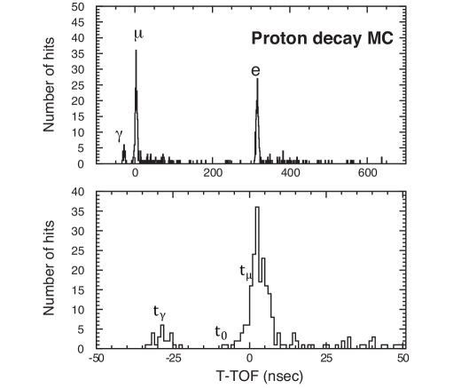
| Prompt | Spectrum | |||||
| [%] | Bkg [/Mtonyr] | [%] | Bkg [/Mtonyr] | [%] | Bkg [/Mtonyr] | [%] |
| 31.0 | 1916.0 | 8.0 | ||||
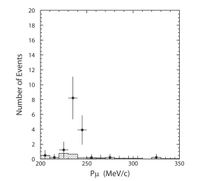
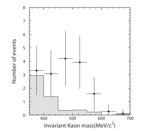
The prompt search method proceeds by identifying fully contained fiducial volume interactions with a single -like ring accompanied by a Michel electron. In order to suppress atmospheric neutrino backgrounds, particularly those with an invisible muon, the muon momentum is required to be MeV/ and the distance between its vertex and that of the Michel electron cannot exceed 200 cm. Events with high momentum protons that create a -like Cherenkov ring are rejected using a dedicated likelihood designed to select in favor of genuine muons based on the PMT hit pattern and the Cherenkov opening angle. Searching backward in time from the muon candidate, de-excitation ray candidates are identified as the largest cluster of PMT hits within a 12 ns sliding window around the time-of-flight-subtracted time distribution. The time difference between the center of the time window containing the candidate, , and the muon time, is then required be consistent with decay of a kaon, ns (). Finally, only events whose number of hits in this window, , is consistent with 6 MeV of energy deposition () are kept. The left panel of Figure 166 shows the expected distribution after all selection cuts have been applied assuming a proton lifetime of years, which is slightly less than the current Super-K limit.
The second search ( spectrum) method also focuses on identifying the monochromatic muon but with relaxed search criterion. Only those cuts applied before the proton likelihood cut are used. A fit is then applied to the resulting muon momentum distribution to identify any proton decay-induced excess of muon events over the considerable atmospheric neutrino background.
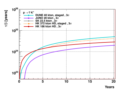
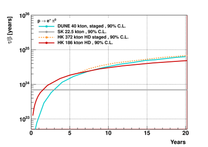
Like the prompt search, the search relies on more sophisticated event selections to identify the signal. While the momentum of both the and from the decay will be 205 MeV/, the former does not deposit enough light to be reconstructed fully. To compensate for this the search method focuses on PMT hits opposite the direction of a at the correct momentum. Fully contained events with one or two reconstructed rings, all of which are -like, are selected. In addition there should be one Michel electron from the charged pion decay chain. For two-ring events the invariant mass is required to be consistent with that of a neutral pion, MeV/. Further, the total momentum should be between 175 and 250 MeV/. At this stage the light is identified as electron-equivalent visible energy between 7 and 17 MeV located at an angular separation between 140 and 180 degrees from the candidate’s direction. Finally a likelihood method is used to evaluate the consistency of this light pattern with that produced by a . Details of the full search method are documented elsewhere Abe et al. (2014g). In addition, as in the search, the number of tagged neutron candidates is required to be zero.
Table 46 summarizes the expected signal efficiency and background rates for each of the search methods. Accompanying systematic errors have been calculated based on Super-K methods Abe et al. (2014g) and are included in the table. Assuming a proton lifetime close to current Super-K limits, Figures 166 show the reconstructed muon momentum from the prompt gamma search and the reconstructed kaon mass spectrum from the search. Note that while the latter is unused in the analysis itself it provides a demonstration of the signal reconstruction since the proton mass for this decay mode cannot be reconstructed. The expected discovery potential and sensitivity of Hyper-K in comparison with other experiments appears in Figures 168 and 168.
III.2.1.3 Sensitivity study for other nucleon decay modes
Although the decay mode is predicted to be dominant in many GUT models, a variety of other decay modes are possible, each with a sizable branching ratio. Table 47 shows the branching ratio distribution and ratio of neutron to proton lifetimes as predicted by several GUT models. The diversity in these predictions suggests that in order to make a discovery and to subsequently constrain proton decay models, it is critical to probe as many nucleon decay modes as possible. Fortunately, Hyper-Kamiokande is expected to be sensitive to many decay modes beyond the two standard decays discussed above.
| Br.() | |||||
| SU(5) | SO(10) | ||||
| References | Machacek (1979) | Gavela et al. (1981) | Donoghue (1980) | Buccella et al. (1989) | Buccella et al. (1989) |
| 33 | 37 | 9 | 35 | 30 | |
| 12 | 7 | 3 | 15 | 13 | |
| 17 | 2 | 21 | 2 | 2 | |
| 22 | 18 | 56 | 17 | 14 | |
| Others | 17 | 35 | 11 | 31 | 31 |
| 0.8 | 1.0 | 1.3 | |||
Hyper-Kamiokande’s sensitivity to other nucleon decay modes has been estimated based in part on efficiencies and background rates from Super-Kamiokande Nishino et al. (2009). Table 48 shows the 90 CL sensitivities with a 1.9 Megatonyear exposure in the 1TankHD configuration. Under these conditions Table 49 shows the discovery potential of Hyper-K for a selected number of decay modes after a 1.9 Mtonyear exposure.
| Mode | Sensitivity (90 CL) [years] | Current limit [years] |
|---|---|---|
| 7.8 | 1.6 | |
| 3.2 | 0.7 | |
| 7.7 | 0.77 | |
| 4.3 | 1.0 | |
| 4.9 | 0.47 | |
| 0.63 | 0.07 | |
| 0.22 | 0.06 | |
| 0.86 | 0.16 | |
| 1.3 | 0.28 | |
| 2.0 | 0.53 | |
| 1.8 | 0.35 |
The decay modes in Table 48 all conserve baryon number minus lepton number, . However, the conserving mode, , was also given attention and searched for by Super-Kamiokande. In , the stops in the water and decays into . The final state particles observed in are and . Both and have monochromatic momenta as a result of originating from two-body decays. Furthermore, the timing of the rings are delayed with respect to the rings because of the lifetime. In SK-II, the estimated efficiencies and the background rate are 8.4% and 1.1 events/Megatonyear, respectively. From those numbers, the sensitivity to the mode with a 1.9 Megatonyear exposure is estimated to be 1.0 years.
The possibility of oscillation is another interesting phenomenon; it violates baryon number by = 2. These oscillations have been searched for in Super-Kamiokande with an exposure of 0.09 Megatonyear Jang (2007). Further improvement of the oscillation search is expected in Hyper-Kamiokande.
| Mode | [years] |
|---|---|
| 6.3 (8.0) | |
| 2.0 (2.5) | |
| 6.9 (8.7) | |
| 3.0 (3.9) | |
| 3.4 (4.7) | |
| 3.4 (5.0) | |
| 1.3 (1.6) | |
| 5.4 (6.9) | |
| 0.78 (1.0) |
| Mode | [years] |
|---|---|
| 1.3 (1.6) | |
| 1.1 (1.5) | |
| 1.1 (1.5) | |
| 6.2 (8.1) |
| Mode | Sensitivity (90 CL) [years] | Current limit [years] |
|---|---|---|
| 10.2 | 1.7 | |
| 10.7 | 2.2 | |
| 31.1 | 7.9 | |
| 33.8 | 4.1 | |
| 23.4 | 5.5 | |
| 6.2 | 2.6 | |
| 4.2 | 2.0 | |
| 6.0 | 3.0 |
In addition to conserving modes several other nucleon channels are available. Unification schemes invoking left-right symmetry (c.f. Pati and Salam (1974)) predict trilepton decays such as , which violate by two units (). Though there are two particles in the final state that are invisible to Hyper-Kamiokande, the presence of a positron or muon from such decays can, in principal, be detected. While this type of single charged lepton signature would naturally be subject to large atmospheric backgrounds, with a sufficiently large decay rate, spectral information can be used to separate the two. Going one step farther, then, spectral analysis makes it possible to search for generic decay modes as well, such as , where is an unknown and unseen particle.
Though only single nucleon decays have been considered up until this point, it is worth noting that dinucleon processes, in which a neutron-proton (or proton-proton) pair decays into a pair of leptons, can also be studied at Hyper-Kamiokande. Modes where , such as , appear in models with extended Higgs sectors Fileviez Perez and Wise (2013) and have connections to Baryogenesis. Interestingly, these models have the additional property that the single nucleon decay modes are suppressed relative to the dinucleon decays. This wealth of predictions for possible channels further emphasizes the need to search for as many nucleon decay signatures as possible in the quest for grand unification. Table 50 lists Hyper-K’s expected sensitivity to both and decays for a 5.6 Mtonyear exposure. While searches for these modes are dominated by the atmospheric neutrino background, Hyper-K can be expected to extend existing limits by a factor of three to ten if no signal is observed.
III.2.2 Impact of Photocathode Coverage and Improved Photosensors
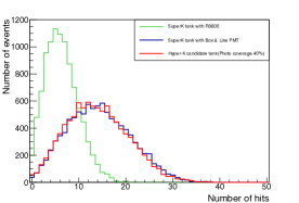
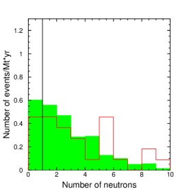
Improved photon collection with larger photocathode coverages, higher quantum efficiency photosensors, and their combination have a dramatic effect on the physics sensitivity of Hyper-K. Nucleon decay searches, in particular, are expected to benefit significantly from enhanced ability to detect low levels of Cherenkov light. With the large exposures Hyper-K will provide, the atmospheric neutrino background to these searches becomes sizable and can inhibit the discovery potential of the experiment. However, these same backgrounds are often expected to produce neutrons either directly through the CC interaction of antineutrinos or indirectly via the secondary interaction of hadrons in the interaction. Proton decay events, in contrast, are only rarely expected to be accompanied by neutrons. Though such neutrons are ordinarily transparent to water Cherenkov detectors, Super-Kamiokande has demonstrated the ability to tag the 2.2 MeV photon emerging from neutron capture on hydrogen, . Naturally this channel will be available to Hyper-K. In this section we compare the performance of Hyper-K 1TankHD configuration with its 40% photocathode coverage and high quantum efficiency photosensors against a design with 20% coverage and the same PMTs used in Super-K.
Since 2.2 MeV is only barely visible in Super-K, their tagging algorithm makes use of a neural network to isolate signal neutrons, which are correlated spatially and temporally with the primary neutrino interaction, from background sources. Though the method achieved 20.5% tagging efficiency with a 1.8% false tag probability Wendell (2015) it is worth noting that so far it has only been successful during the SK-IV phase of the experiment. Despite 40% photocathode coverage with Hamamatsu R3600 50 cm PMTs, on average the neutron capture signal produces only 7 hits in the detector Wendell (2015). Since the average photon travel length in Hyper-K will be larger than that of SK-IV, in order to take advantage of the neutron signal it is essential to augment Hyper-K’s photon yield wherever possible.
While a full analysis of Hyper-K’s neutron tagging capability is in development a rough estimation for the 1TankHD design (c.f. Section II.2.6) has been determined via simulation. Figure 169 shows the number of hit photosensors for a simulated sample of the 2.2 MeV ray emitted when a neutron captures on a proton for three water Cherenkov detector configurations. The green distribution shows the response of a Super-K-sized detector with 40% photocathode coverage by Hamamatsu R3600 PMTs, while the blue line shows the effect of implementing the HQE Box and Line photosensors. Using the same photocathode coverage and the latter photosensors but with an enlarged tank representative of a the Hyper-K design (60 m diameter and 74 m height results) results in the red curve. Using these distributions the number of hit photosensors which reproduces the tagging efficiency realized in the Super-K analysis is chosen as the metric to represent the expected tagging efficiency at Hyper-K. For the Super-K distribution gamma events with more than nine PMT hits result in an 18% tagging efficiency. Assuming the same 10 hit threshold can be used at Hyper-K, the equivalent distribution (red curve in the figure) suggests 73% efficiency can be achieved. The sensitivity studies presented in this document assume this number for Hyper-K when neutron tagging is employed. In what follows sensitivity estimates are presented assuming both this and the Super-K tagging efficiency for comparison.
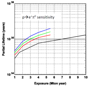
Based on MC studies, the fraction of atmospheric neutrino backgrounds to the search which are accompanied by at least one final state neutron is . At the same time, only 4% of signal MC events have such a neutron. The multiplicity distribution for the background sample is shown in Figure 170. Due to the presence of high multiplicity events, assuming 70% neutron tagging efficiency, the neutron background can be reduced by approximately 70% (green histogram) by rejecting events with one or more neutron tags. Reducing the background in this manner will have a large impact on the sensitivity to this decay mode, as shown in Figure 171. In the figure the black curve represents the sensitivity of the analysis without neutron tagging and cuts defining only a single signal region. If that signal region is divided into a piece where free proton decays are enhanced () and a region with predominantly bound decays (), as is assumed in the analysis above, the resulting sensitivity is shown by the red line. Further, if the total background is then reduced by 50% (70%), by the introduction of neutron tagging, the sensitivity improves as shown in the green (blue) lines. With these background reductions Hyper-K will require exposures of 3.0 and 2.4 Mton years to reach lifetime limits of years if no signal is observed. Without any background reduction 7.0 Mtonyears are required.
It should be noted that is not the only mode that is expected to benefit from a higher photon yield; Most modes are similarly expected to have reduced atmospheric neutrino backgrounds with neutron tagging. However, the search can also benefit from enhanced light collection to improve the signal efficiency. Its two lowest efficiency, but most sensitive search modes, one in which the decay is accompanied by a prompt 6.3 MeV de-excitation from the recoiling nucleus and the other in which the decays into , both have components that are looking for small amounts of light. Higher photon yields are thus connected directly to efficiency improvements in these channels.
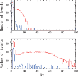
As discussed above, the search for the prompt ray is done using the number of hit PMTs within a 12 nsec wide timing widow prior to the muon candidate from the (c.f. Figure 165). Figure 172 shows this distribution for the proton decay signal (red) and background from atmospheric neutrinos (blue) for a Hyper-K design with 20% photocathode coverage (upper panel) and the 1TankHD design. In the latter study the photon yield is assumed to be 1.9 times greater than that of the PMT used in the 20% coverage design and with half the intrinsic timing resolution of the photosensor (1 nsec at 1 p.e.). Additionally, these sensors are assumed to have a higher dark rate of 8.4 kHz. For both detector configurations the peak near zero corresponds to events in which a was not found; these hits are dominated by dark noise. Though this peak is not well separated from the feature at higher hits in the 20% coverage configuration, with improved photosensors and 40% coverage a clear distinction between the two can be seen. Further, since the search is designed to avoid hit contamination from the , the narrower timing resolution of the improved sensors means that the search can occur closer in time to the muon. Practically speaking, this means with earlier decay times can be used in the analysis as shown in Figure 173. Both of these effects lead to an overall increase in the signal efficiency of the mode. Based on this distribution the proton decay signal region is defined as hits for the 20% coverage design and for the 1TankHD case.
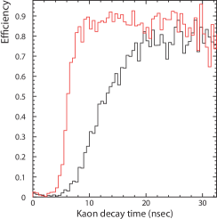
Accordingly, the signal efficiency for the prompt tag method to search for increases from 6.7% in the design with 20% photocathode coverage to 12.7% in the 1TankHD configuration. Though not detailed here, improved tagging of the from the component of this search yields 10.2% signal efficiency in the 1TankHD design compared to 6.7% in the 20% coverage case. As in the study above, if neutron tagging with 70% efficiency is assumed (c.f. Figure 171) the background to these search methods can be reduced to 0.87 and 0.71 events/Mtonyear, respectively. For comparison the background rates are 2.8 and 3.4 events/Mtonyear without neutron tagging. Figure 174 shows the corresponding sensitivity curves for both the design with 20% coverage (black) and for the 1TankHD design (red). Two vertical lines at exposures of 1.9 and 5.6 Mtonyear in the figure denote positions of comparable sensitivity between the two designs.
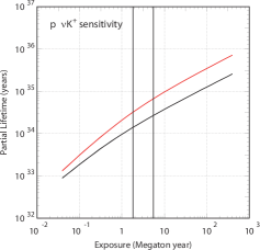
It should be noted that since backgrounds for the Super-K neutron tagging algorithm are taken from its data, it is difficult to provide a realistic estimate of the potential of a similar algorithm at Hyper-K at this time. However assuming similar performance, Hyper-K’s dramatic improvement in proton decay sensitivity makes this topic among the most fundamental to the development of its future program. It is clear that the potential for a discovery is connected to Hyper-K’s background reduction and efficiency enhancement capabilities, both of which are realizable with higher photon yields.
III.3 Neutrino Astrophysics and Geophysics
III.3.1 Supernova
III.3.1.1 Supernova burst neutrinos
III.3.1.1.1 Introduction
Core-collapse supernova explosions are the last process in the evolution of massive (Msun) stars. Working their way successively through periods of predominantly hydrogen fusion, helium fusion, and so on, eventually silicon fusion starts making iron. Once an iron core has formed, no more energy can be released via its fusion into still-heavier elements, and the hydrodynamic balance between gravity and stellar burning is finally and catastrophically disrupted. The sudden gravitational collapse of their iron cores – which will go on to form either a neutron star or a black hole – is the main source of energy from this type of supernova explosion. The energy released by a supernova is estimated to be ergs, making it one of the most energetic phenomena in the universe. Since neutrinos interact weakly with matter, almost 99% of the released energy from the exploding star is carried out by neutrinos. As a result, the detection of supernova neutrinos gives direct information of energy flow during the explosion. The neutrino emission from a core collapse supernova starts with a short (10 millisecond) burst phase of electron captures () called the neutronization burst, which releases about ergs. Following that, the majority of the burst energy is released by an accretion phase (1 second) and a cooling phase (several seconds) in which all three flavours of neutrinos (as well as anti-neutrinos) are created.
The observation of a handful (25 in total) of supernova burst
neutrinos from SN1987a by the Kamiokande, IMB, and Baksan experiments
proved that the basic scenario of the supernova explosion was correct.
However, more than three decades later the detailed mechanism of
explosions is still not known.
Achieving the necessary conditions
for a supernova explosion in computer simulations has been a
long-standing challenge.
Recently, successful supernova explosions in two-dimensional and
three-dimensional simulations have been reported, the details of which will be
described laterTamborra et al. (2013); Blondin et al. (2003); Scheck et al. (2008); Takiwaki and Kotake (2017).
Though several models have produced successful
supernova explosions in simulations,
detecting supernova neutrinos will provide further input to improve the physics accuracy of the models.
Hyper-K can detect neutrinos with energy down to 3 MeV and can point the supernova, due to its event-by-event directional sensitivity.
Because the supernova neutrinos are detected as a burst in a short time period, we can neglect the low energy radioactive backgrounds.
The localization in time also makes it possible to utilize most of full inner volume for our analysis, 220 kt for each tanks.
Compared with the current or planned experiments, Super-K, the ice Cherenkov detector IceCube/PINGU Aartsen et al. (2014) and large liquid Ar TPC detectors like DUNE,
Hyper-K has several advantages for the supernova measurement.
The first advantage is the large volume and statistics.
Hyper-K will have a FV of 8 times to 16 times larger than the Super-K detector, resulting in a commensurate increase in the number of detected supernova neutrinos and sensitivity to supernovae occurring in nearby galaxies.
Likewise, Hyper-K will be significantly larger than DUNE
with mass in the tens of kt scale.
Furthermore, Hyper-K primarily detects anti-electron-neutrino from the
supernova explosion using the inverse beta decay reaction
(), unlike LArTPC detectors which
primarily detect electron neutrinos.
Large neutrino telescopes like IceCube/PINGU has capability of huge
statistics detection, however, they would detect only single PMT hits from such low energy neutrino events, allowing them to separate supernova neutrinos from their dark noise only on a statistical basis.
In contrast, every single event will be reconstructable with Hyper-K down to an energy analysis threshold of 3 MeV.
Our precise event-by-event measurement will be essential for the comprehensive study of supernova neutrinos, especially with the detailed and time-dependent energy spectrum.
With these advantages, Hyper-K is able to perform unique measurements to reveal the mechanism of supernova explosions.
III.3.1.1.2 Expected observation in Hyper-Kamiokande
In order to correctly estimate the expected number of neutrino events detected in Hyper-K, we must consider the neutrino oscillation due to the MSW matter effect through the stellar medium. The flux of each neutrino type emitted from a supernova is related to the originally produced fluxes (, and , where is and ) by the following formulas Dighe and Smirnov (2000); Fogli et al. (2005) :
For normal hierarchy,
and, for inverted hierarchy,
where is the crossing probability through the matter resonant layer corresponding to . () for adiabatic (non-adiabatic) transition. Recent measurement of indicates the adiabatic transition () for the matter transition in the supernova envelope. The supernova neutrino spectrum is affected not only by stellar matter but also by other neutrinos and anti-neutrinos at the high density core (so-called collective effects). These collective effects, which swap the and spectra with those of in certain energy intervals bounded by sharp spectral splits, were first discussed in Duan et al. (2006a, b). This has become an active field of study whose recent investigations include taking into account the possibility of multiple splits Dasgupta et al. (2009), computation with three neutrino flavors Friedland (2010), and utilizing the full multi-angle framework Duan and Friedland (2011). So, in the following description of the performance of the Hyper-Kamiokande detector, three cases are considered in order to fully cover the possible variation of expectations: (1) no oscillations, (2) normal hierarchy (N.H.) with , and (3) inverted hierarchy (I.H.) with . The process depends critically on ; in what follows we assume . Concerning the neutrino fluxes and energy spectra at the production site, we used results obtained by the Livermore simulation Totani et al. (1998).
Figure 175 shows time profiles for various interactions expected at the Hyper-Kamiokande detector for a supernova at a distance of 10 kiloparsecs (kpc). This distance is a bit farther than the center of the Milky Way galaxy at 8.5 kpc; it is chosen as being representative of what we might expect since a volume with a radius of 10 kpc centered at Earth includes about half the stars in the galaxy.
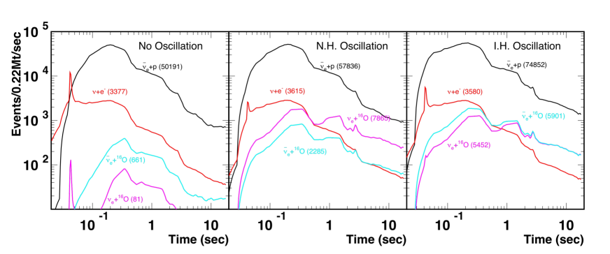
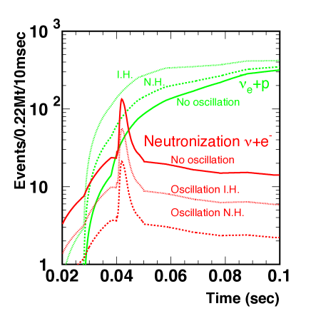
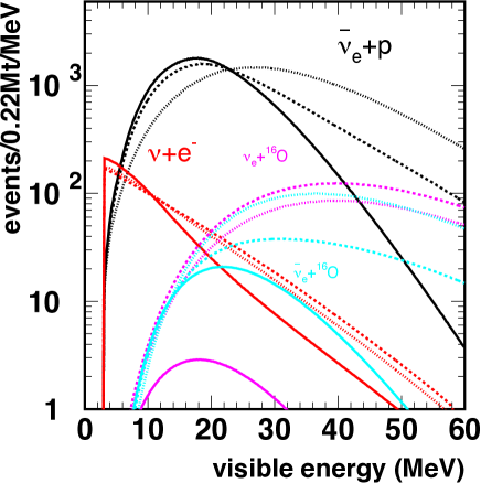
The three graphs in the figure show the cases of no oscillation, normal hierarchy and inverted hierarchy, respectively. Colored curves in the figure show event rates for inverse beta decay (), -scattering(), O CC(), and O CC (). The burst time period is about 10 s and the peak event rate of inverse beta decay events reaches about 50 kHz at 10 kpc. The DAQ and its buffering system of Hyper-K will be designed to accept the broad range of rates, for a galactic SN closer than 10 kpc. A sharp timing spike is expected for -scattering events at the time of neutronization. Fig. 176 shows the expanded plot around the neutronization burst peak region. We expect 9, 23 and 55 -scattering events in this region for a supernova at 10 kpc, for N.H., I.H., and no oscillation respectively. Although the number of inverse beta events is 100 (N.H.), 210 (I.H.), and 60 (no oscillation) in the 10 ms bin of the neutronization burst, the number of events in the direction of the supernova is typically 1/10 of the total events. So, the ratio of signal events (-scattering) to other events (inverse beta) is expected to be about 9/10 (N.H.), 23/21 (I.H.) and 55/6 (no oscillation).
The energy distributions of each interaction are shown in Fig. 177, where the energy is the electron-equivalent total energy measured by a Cherenkov detector. The energy spectrum of can be extracted from the distribution.
Figure 178 shows the expected number of supernova neutrino events at Hyper-K versus the distance to a supernova.
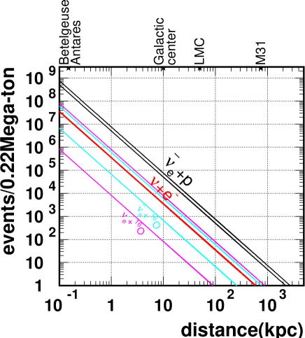
At the Hyper-Kamiokande detector, we expect to see about 50,000 to 75,000 inverse beta decay events, 3,400 to 3,600 -scattering events, 80 to 7,900 O CC events, and 660 to 5,900 O CC events, in total 54,000 to 90,000 events, for a 10 kpc supernova. The range of each of these numbers covers possible variations due to the neutrino oscillation scenario (no oscillation, N.H., or I.H.). Even for a supernova at M31 (Andromeda Galaxy), about 10 to 16 events are expected at Hyper-K. In the case of the Large Magellanic Cloud (LMC) where SN1987a was located, about 2,200 to 3,600 events are expected.
The observation of supernova burst neutrino and the directional
information can provide an early warning for electromagnetic observation
experiments, e.g. optical and x-ray telescopes.
Figure 179 shows expected angular
distributions with respect to the direction of the supernova for four
visible energy ranges. The inverse beta decay events have a nearly
isotropic angular distribution. On the other hand, -scattering
events have a strong peak in the direction coming from the supernova.
Since the visible energy of -scattering events are lower than
the inverse beta decay events, the angular distributions for lower energy
events show more enhanced peaks. The direction of a supernova at
10 kpc can be reconstructed with an accuracy of about 1 to 1.3 degrees with Hyper-K,
assuming the performance of event direction reconstruction similar to Super-K Abe et al. (2016b).
This pointing accuracy will be precise enough for the multi-messenger measurement of supernova at the center of our galaxy,
with the world’s largest class telescopes, Subaru HSC and future LSST telescope Nakamura et al. (2016).
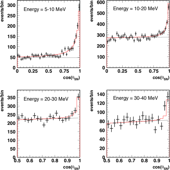
III.3.1.1.3 Physics impacts
The shape of the rising time of supernova neutrino flux and energy strongly depends on the model. Figure 180 shows inverse beta decay event rates and mean energy distributions predicted by various models Totani et al. (1998); Takiwaki et al. (2014); Tamborra et al. (2014); Dolence et al. (2015); Pan et al. (2016); Nakazato et al. (2015); Bruenn et al. (2016) for the first 0.3 sec after the onset of a burst. The statistical error is much smaller than the difference between the models, and so Hyper-K should give crucial data for comparing model predictions.
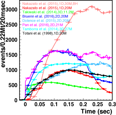
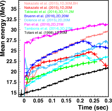
The left plot in Fig. 180 shows that about 150-500 events are expected in the first 20 millisecond bin. This means that the onset time can be determined with an accuracy of about 1 ms. This is precise enough to allow examination of the infall of the core in conjunction with the signals of neutronization as well as possible data from future gravitational wave detectors. Our measurement will also provide an opportunity to observe black hole formation directly, as a sharp drop of the neutrino flux Sekiguchi and Shibata (2011).
We can use the sharp rise of the burst to make a measurement of
the absolute mass of neutrinos. Because of the finite mass of
neutrinos, their arrival times will depend on their energies. This
relation is expressed as
| (42) |
where is the time delay with respect to that assuming zero neutrino mass, is the distance to the supernova, is the absolute mass of a neutrino, and is the neutrino energy. Totani Totani (1998) discussed Super-Kamiokande’s sensitivity to neutrino mass using the energy dependence of the rise time; scaling these results to the much larger statistics provided by Hyper-K, we expect a sensitivity of 0.5 to 1.3 eV for the absolute neutrino mass Totani (2005). Note that this measurement of the absolute neutrino mass does not depend on whether the neutrino is a Dirac or Majorana particle.
Hyper-K can also statistically extract an energy distribution of events using the angular distributions in much the same way as solar neutrino signals are separated from background in Super-K. Although the effect of neutrino oscillations must be taken into account, the spectrum gives another handle on the temperature of neutrinos. Hyper-K will be able to evaluate the temperature difference between and . This would be a valuable input to model builders. For example, the prediction from many of the models that the energy of is less than can be confirmed. The temperature is also critical for the nucleosynthesis via supernova explosion Hayakawa et al. (2016).
From recent computer simulation studies, new characteristic
modulations of the supernova neutrino flux are proposed.
These modulations are due to the dynamic motions in the supernovae such as convection.
The stall of shock wave after core bounce has been an issue in supernova computer simulations, which was not able to achieve successful explosions.
These dynamic motions enable the inner materials to be heated more efficiently by the neutrinos from collapsed core, and realize the shock wave revival.
Such modulations can be detected as a variance of the neutrino event rate in Hyper-K.
It will be the clear evidence that neutrino is the driver of supernova burst process.
One source of such modulation is the Standing Accretion Shock
Instability (SASI) Tamborra et al. (2013); Blondin et al. (2003); Scheck et al. (2008).
Figure 181 shows the detection rate modulation
in Hyper-K, induced by SASI.
The modulation can be observed as a variance of 10% of the number of supernova events in Hyper-K detector
Tamborra et al. (2013).
This flux variance caused by SASI has a characteristic peak in the frequency space.
When we assume a 3% flux modulation on the total supernova flux,
though the amount of the flux modulation depends on several variables, e.g. progenitor mass or equation of states,
it is possible to see the existence of SASI for the supernovae within about 15 kpc distance.Migenda (2016)
Under this assumption of a 3% flux modulation, we will have chances to prove SASI effects for 90% of galactic supernovae with Hyper-K, compared with only 15% with Super-K.
Another source of modulation is the rotation of supernova T. Tomoya (2014); Takiwaki and Kotake (2017).
The size of variation depends on the angle between the direction of
earth and the rotational axis of supernova. When the supernova
rotational axis is orthogonal with the direction to the earth, the
detectable variance will be the maximum. In that case, Hyper-K will
detect a variance of 50% in the number of observed signals
as shown in Figure 181.
The observation of these modulation with Hyper-K
will be a good test of such simulations and also provide important
information for understanding the dynamics in supernovae.
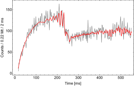
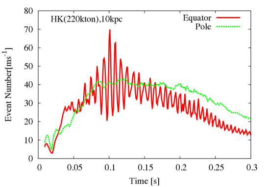
Neutrino oscillations could be studied using supernova neutrino events. There are many papers which discuss the possibility of extracting signatures of neutrino oscillations free from uncertainties of supernova models Totani et al. (1998); Takiwaki et al. (2014); Tamborra et al. (2014); Dolence et al. (2015); Pan et al. (2016); Nakazato et al. (2015); Bruenn et al. (2016). One big advantage of supernova neutrinos over other neutrino sources (solar, atmospheric, accelerator neutrinos) is that they inevitably pass through very high density matter on their way to the detector. This gives a sizeable effect in the time variation of the energy spectrum Schirato and Fuller (2002); Fogli et al. (2005); Tomas et al. (2004). Though the combination of MSW stellar matter effects and collective effects makes the prediction quite difficult Duan et al. (2006a, b); Dasgupta et al. (2009); Friedland (2010); Duan and Friedland (2011), we will still have opportunities to determine the neutrino mass hierarchy from the supernova burst. The first chance is the neutronization burst, where mostly pure will be emitted from the proto-neutron star. Since, the collective effect through interaction can be negligible. The multi-angle effect can also be ignored, because these neutrinos are emitted only from the very center of the supernova. The flux is well predicted and hardly affected by the physics modelling of the EOS or the progenitor mass Kachelriess et al. (2005); Mirizzi et al. (2016). The number of event will be about 50% larger in IH case comparing to NH, after 20 ms from the core bounce. In the succeeding accretion phase, we will have another chance by observing the rise-time of neutrino event rate. The mixing of to , will result in a 100 ms faster rise time for the inverted hierarchy compared to the normal hierarchy case Serpico et al. (2012). We will have fair chance to investigate it for a supernova at the galactic center, see Fig. 180.
In Hyper-K, it could be possible to detect burst neutrinos from supernovae in nearby galaxies. As described above, we expect to observe a very large number of neutrino events from a galactic supernova. However, galactic supernovae are expected to happen once per 30 - 50 years. So, we cannot count on seeing many galactic supernova bursts. In order to examine a variety of supernova bursts, supernovae from nearby galaxies are useful even though the expected number of detected events from any single such burst is small. Furthermore, the merged energy spectrum from these supernovae will be highly useful for understanding that of supernova relic neutrinos (see next sub-section) for the absence of red-shift. The supernova events from nearby galaxies provide a reference energy spectrum for this purpose. The supernovae rate in nearby galaxies was discussed in Ando et al. (2005) and a figure from the paper is shown in Fig. 183. It shows the cumulative supernova rate versus distance and indicates that if Hyper-K can see signals out to 4 Mpc then we could expect a supernova about every three years. It should be noted that recent astronomical observations indicate about 3 times higher nearby supernova rate Horiuchi et al. (2013), compared to the conservative calculation. It is also valuable to mention that two strange supernovae have been found at 2 Mpc distance in the past 11 years observation, which are called dim supernovae Horiuchi et al. (2013). The detections of supernova neutrinos from these dim supernovae will prove their explosion mechanism is core-collapse. Figure 184 shows detection probability versus distance for the Hyper-K detector 1 tank (left) and 2 tanks configuration (right). In this estimate, we required the neutrino energy be greater than 10 MeV in order to reduce background. Requiring the number of neutrino events to be more than or or equal to two (one), the detection probability is 27 to 48% (64 to 80%) with 1 tank, for a supernova at 2 Mpc. The probability will be 3 to 6% (22 to 33%) for the supernovae at 4 Mpc. With 2 tank configuration and 375 kt fiducial volume, the detection probability will be increased to 10 to 18% (40 to 57%) for a supernova at 4 Mpc. If we can use a tight timing coincidence with other types of supernova sensors (e.g. future gravitational wave detectors), we should be able to identify even single supernova neutrinos. We expect to observe 2.4 to 4.6 or 0.6 to 1.4 supernovae with and without dim supernovae within 10 Mpc respectively, during 20 years of Hyper-K one tank operation. Here we required two or more neutrino events for each supernovae, and referred to the nearby galactic supernova rate given by CCSNe counting in ref. Horiuchi et al. (2013). The number of observations can be increased to 5.0 to 8.2 and 1.6 to 3.3 supernovae with and without dim supernova respectively, with Hyper-K staging two tank scenario.
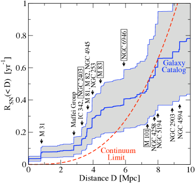
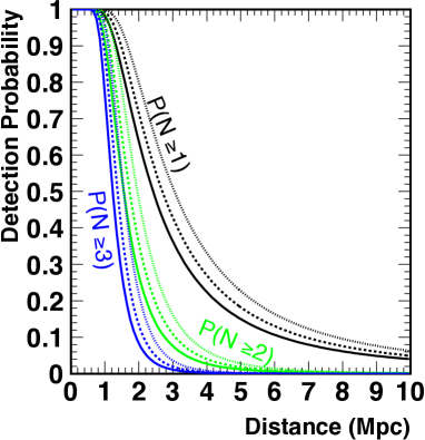
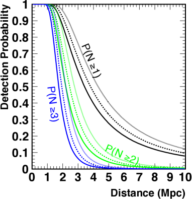
III.3.1.1.4 Summary
The expected number of supernova neutrino events in the Hyper-Kamiokande detector is summarized in Table 51. These events will be enough to provide detailed information about the time profile and the energy spectrum for inspecting supernova explosion mechanism, including black hole formation. They will also provide an opportunity for further physics topics, the neutrino mass, the mass hierarchy and the neutrino oscillations in the supernova. Physics beyond the standard model also can be tested, sterile neutrinos Hidaka and Fuller (2006); Loveridge (2004); Hidaka and Fuller (2007); Tamborra et al. (2012), the neutrino magnetic moment Lattimer and Cooperstein (1988); Barbieri and Mohapatra (1988) the neutrino non-standard interaction Esteban-Pretel et al. (2007); Ohlsson (2013) and the axion Turner (1988); Burrows et al. (1989); Keil et al. (1997); Raffelt (2008); Fischer et al. (2016). The better energy resolution from high photo-coverage will help these analyses. The lower energy threshold will also help to understand the whole picture of supernova explosion. The detection of supernovae in nearby galaxies will be possible even with a single tank, though the number of events will be small. The energy spectrum of these events will still be useful to understand the nature of the supernova explosion.
| Neutrino source | Single Tank (220 kt Full Volume) | 2 Tanks (440 kt Full Volume) | Ref. |
|---|---|---|---|
| 50,000 - 75,000 events | 100,000 - 150,000 events | Vogel and Beacom (1999) | |
| 3,400 - 3,600 events | 6,800 - 7,200 events | ’t Hooft (1971) | |
| CC | 80 - 7,900 events | 160 - 11,000 events | Tomas et al. (2003) |
| CC | 660 - 5,900 events | 1,300 - 12,000 events | Kolbe et al. (2002) |
| (Neutronization) | 9 - 55 events | 17 - 110 events | ’t Hooft (1971) |
| Total | 54,000 - 90,000 events | 109,000 - 180,000 events |
III.3.1.2 High-energy neutrinos from supernovae with interactions with circumstellar material
Core-collapse supernovae are promising sources of high-energy ( GeV) neutrinos as well as multi-MeV neutrinos. The supernova shock propagates in the stellar material and experiences a shock breakout, which can be observed at ultraviolet or X-ray wavelengths. Before the shock breakout, the supernova shock is mediated by radiation since the photon diffusion time is longer than the expansion time. During this time, the conventional cosmic-ray (CR) acceleration is inefficient, so associated neutrino production is not promising. However, as the shock becomes collisionless after the breakout, the CR acceleration starts to be effective Waxman and Loeb (2001); Murase et al. (2011). The situation is expected to be analogous to supernova remnants, which are almost established as CR accelerators and widely believed as the origin of Galactic CRs.
In the early phase just after the breakout, the matter density is still high, so that accelerated CRs are efficiently used for neutrino production via inelastic scatterings. For type II supernovae, which are associated with red super-giants, the released energy of high-energy neutrinos is typically erg Waxman and Loeb (2001). One to two events of GeV neutrinos are expected in a timescale of hours after the core-collapse for a Galactic supernova at 10kpc in Hyper-K 1 tank.
About 10% of core-collapse supernovae show strong interactions with ambient circumstellar material, which are often called interaction-powered supernovae. If the circumstellar material mass is -, the released high-energy neutrino energy reaches - erg Murase et al. (2011). For example, Eta Carinae at 2.3 kpc is an interesting candidate that showed violent mass eruptions in the past. If a real supernova occurs and the ejecta collides with the circumstellar material shell with , one may expect events with Hyper-K. However, because of the long duration (from months to years), the signal can overwhelm the background only at early times and sufficiently high energies.
High-energy neutrinos from supernovae are detectable hours to months after the core-collapse, and detecting the signals will give us new insights into supernova physics, such as how collisionless shocks are formed and CR acceleration starts, as well as the connection to supernova remnants as the origin of Galactic CRs. We may be able to see the time evolution of multi-energy neutrino emission from the core-collapse to shock breakout and following interactions with the circumstellar material.
III.3.1.3 Supernova relic neutrinos
The neutrinos produced by all of the supernova explosions since the beginning of the universe are called supernova relic neutrinos (SRN) or diffuse supernova neutrino background (DSNB). They must fill the present universe and their flux is estimated to be a few tens/cm2/sec. If we can detect these neutrinos, it is possible to explore the history of how heavy elements have been synthesized since the onset of stellar formation.
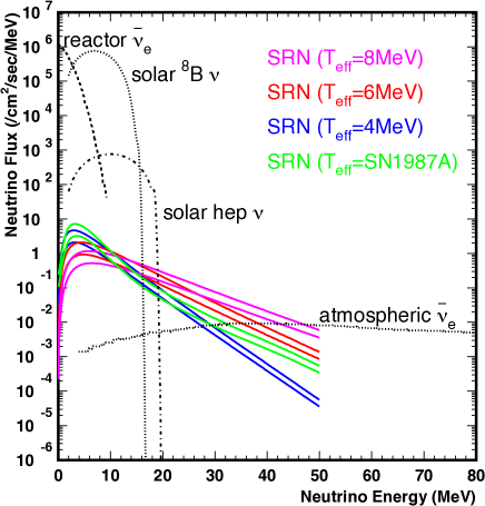
Figure 185 shows the SRN spectra predicted by various models. Although searches for SRN have been conducted at large underground detectors, no evidence of SRN signals has yet been obtained because of the small flux of SRN. The expected inverse beta () event rate at Super-Kamiokande is 0.8-5 events/year above 10 MeV, but because of the large number of spallation products and the low energy atmospheric neutrino background (decay electrons from muons below Cherenkov threshold produced by atmospheric muon neutrinos, the so-called invisible muon background), SRN signals have not yet been observed at Super-Kamiokande. In order to reduce background, lower the energy threshold, individually identify true inverse beta events by tagging their neutrons, and thereby positively detect SRN signals at Super-Kamiokande, a project to add 0.1% gadolinium (Gd) to tank (the SK-Gd project, called GADZOOKS! project previously) was proposed by J.F. Beacom and M.R. Vagins Beacom and Vagins (2004). As the result of very active R&D works, the detector upgrade to SK-Gd is planned in 2018. The first observation of the SRN could be made by the SK-Gd project. However, a megaton-scale detector is still desired to measure the spectrum of the SRN and to investigate the history of the universe because of its huge statistics as shown in Fig. 186. Furthermore, Hyper-K could measure the SRN neutrinos at E = 16-30 MeV, while the SK-Gd project concentrates on the energy of 10-20 MeV. These observation at a different energy region can measure the contribution of extraordinary supernova bursts on the SRN, e.g. black hole formation Lunardini (2009); Horiuchi . Figure 187 shows the SRN signals in Hyper-K fiducial volume, with a different fraction of black hole formations. Because the successful formation of black hole depends on the initial mass and metallicity of the progenitor, the rate will provide information of the history about the formation of stars and their metallicity.
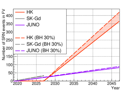
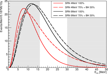
Figure 188 shows expected SRN signals at Hyper-K with 10 years’ livetime. Because of the high background rate below 20 MeV from spallation products, the detection of SRN signals is limited to above 16 MeV, while above 30 MeV the atmospheric neutrino backgrounds completely overwhelm the signal. Considering the event selection efficiency after spallation product background reduction, the expected number of SRN events in E = 16 to 30 MeV is about 70 (140) after 10 (20) years observation with Hyper-K 1 tank. The statistical error will be 17 (25) events, corresponding to an observation of SRN in the energy range 16 to 30 MeV with 4.2 (5.7) significance (fig. 189). Here, we assumed the flux prediction described in ref. Ando et al. (2003) and neutron tagging using MeV with the tagging efficiency of 70%.
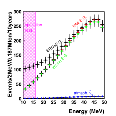
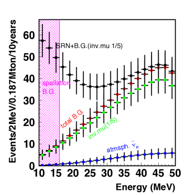
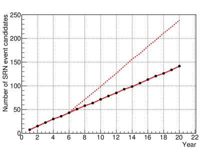
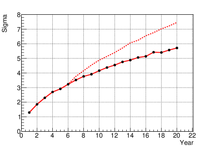
It is still important to measure the SRN spectrum down to 10 MeV in order to explore the history of supernova bursts back to the epoch of red shift (z) 1. Therefore, in the following discussion of the expected SRN signal with gadolinium neutron tagging, we assume that an analysis with a lower energy threshold of 10ṀeV is possible. Inverse beta reactions can be identified by coincident detection of both positron and delayed neutron signals, and requiring tight spatial and temporal correlations between them. With 0.1% by mass of gadolinium dissolved in the water, neutrons are captured on gadolinium with about 90% capture efficiency; the excited Gd nuclei then de-excite by emitting 8 MeV gamma cascades. The time correlation of about 30 sec between the positron and the Gd(n,)Gd cascade signals, and the vertex correlation within about 50 cm are strong indicators of a real inverse beta event. Requiring both correlations (as well as requiring the prompt event to be Cherenkov-like and the delayed event to be isotropic) can be used to reduce background of spallation products by many orders of magnitude while also reducing invisible muon backgrounds by about a factor of 5. The expected number of SRN events in the energy range of 10-30 MeV is about 280 (390) with 10 years of live time with Gd-loaded Hyper-K 1 tank (staging 2 tanks). In addition, by comparing the total SRN flux with optical supernova rate observations, a determination of the fraction of failed (optically dark) supernova explosions, currently unknown but thought to occur in not less than 5% and perhaps as many as 50% of all explosions, will be possible. Possible backgrounds to the SRN search down to 10 MeV are (1) accidental coincidences with the spallation event, (2) spallation products with accompanying neutrons, and (3) the resolution tail of the reactor neutrinos. For (1) accidental coincidences, the possible source of the prompt event is the spallation products. By requiring time coincidence, vertex correlation and energy and pattern of the delayed event, the accidental coincidence rate can be reduced by a factor about 5 and can be below the level of the expected SRN signal. For (2) spallation products with accompanying neutrons, the only possible spallation product is 9Li and an estimation by a Geant4 simulation is shown in Fig. 190. Because of the short half-life of 9Li ( sec), a high rejection efficiency of 99.5% is expected. With this expectation, the 9Li background is less than the signal level above 12 MeV; this could be lowered by further development of the background reduction technique. For (3) the resolution tail of the reactor neutrinos, the estimated background rate is about 100(20)/10 years above 10 MeV (11 MeV) as shown in Fig. 190 with full reactor intensity.
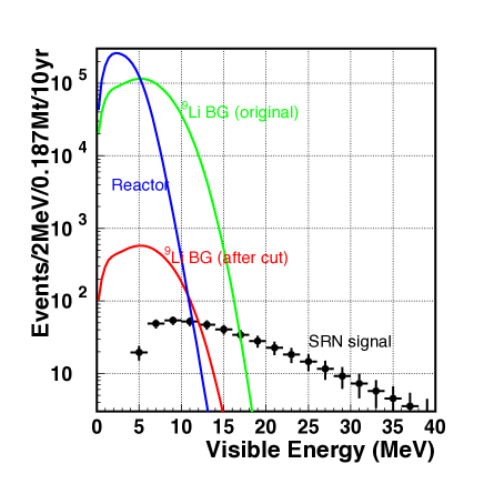
III.3.2 Dark matter searches
Despite overwhelming evidence for the existence of dark matter in the universe, it has yet to been definitively identified or detected in terrestrial experiments. Based on astronomical observations it is known to have gravitational interactions and lacks electromagnetic interactions, but whether or not it carries the weak, strong, or some other interactions remains an open question. Assuming that dark matter is a particle with weak interactions, several direct detection experiments have looked for evidence of so-called WIMP elastic scattering off target nuclei. It is thought though that the self-interaction or decay of dark matter particles bound in strong gravitational potentials, such as those of the milky way galaxy itself or even our sun, may produce standard model particles. In particular, neutrinos may be produced either through direct annihilation or decay of dark matter particles or through the decays of heavier particles produced in these processes, and can be observed at Hyper-Kamiokande. In this case the atmospheric neutrino sample described in Section III.1.2 becomes an overwhelming background. However, a potential dark matter signal is expected to have an angular distribution peaked sharply near the center of the binding potential, which at Hyper-Kamiokande would manifest as the direction towards the galactic center, the sun, or the Earth. By studying the angular distance to these sources it is possible to extract the dark matter signal since the atmospheric neutrino background is expected to be uniformly distributed in this coordinate, particularly for neutrinos from the sun or galactic center. It should be noted that the momentum distribution of the signal is important for extracting the mass of the dark matter candidate producing any observed neutrino event excess.
In the analyses below dark matter is assumed to produce standard model particles such as , , , , and each with 100% branching fraction. The expected distribution of signal neutrinos is simulated and searched for using the same analysis samples described in previous sections. Unlike other indirect detection experiments, such as the neutrino telescopes, Hyper-Kamiokande is expected to have superior sensitivity to lower mass (below 100 GeV/) WIMPS and the ability to resolve a signal with both and components. Hyper-K’s expected sensitivity to WIMP annihilation in the galactic center and the Earth after a 1.9 Mton year exposure is presented below.
III.3.2.1 Search for WIMPs at the Galactic Center
Dark matter trapped in the gravitational potential of galaxies is said to form a halo. Halo models predict dark matter density distributions that peak sharply near the center of a given galaxy and drop with radial distance. For example, for the Milky Way galaxy the expected density distribution at the position of our solar system, kpc, is roughly 1000 times smaller than that at the galactic center in the NFW model Navarro et al. (1996). When simulating the expected signal distribution expected at Hyper-Kamiokande a diffuse dark matter profile following the full NFW density distribution is assumed and accordingly the signal is expected to arise primarily from the galactic center.
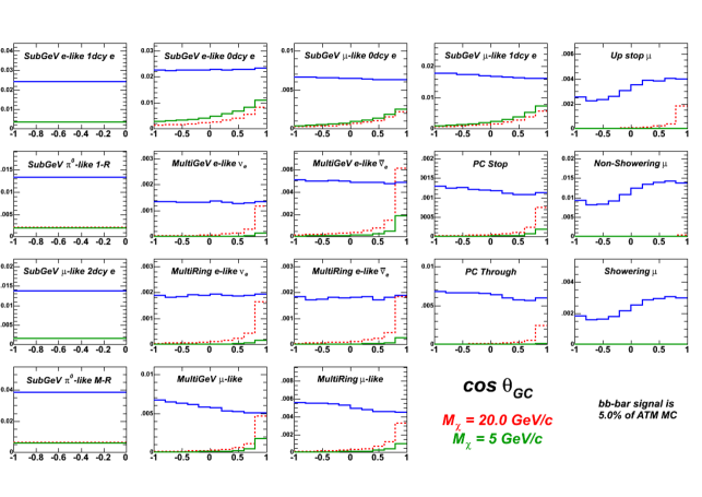
The differential neutrino flux arising from WIMP annihilation into the standard model particles listed above is simulated using the DarkSUSY package Gondolo et al. (2005), and the resulting spectrum adjusted to account for oscillations on the way to the detector. An independent set of atmospheric neutrino MC is reweighted to this distribution to give a reconstructed signal MC at Hyper-Kamiokande. In computing the sensitivity to an additional neutrino source, the analysis samples are rebinned in momentum and , where is the angle between the galactic center position (RA = 266∘, Dec = -28∘) and the reconstructed direction. Figure 191 shows the distributions of the atmospheric neutrino background and two WIMP hypotheses for each of the analysis samples. During the fit MC data sets without a WIMP signal are fit against a PDF built from the atmospheric background MC plus a WIMP signal modified by a normalization parameter, . Here the maximum value of that is consistent with the background-only model within errors is used to compute the upper limit on the amount of additional neutrinos from the galactic center allowed after a 3.8 Mtonyear exposure of Hyper-K.
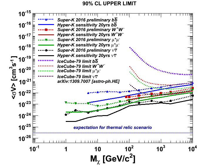
Unlike direct detection experiments this search method is insensitive to the WIMP-nucleon interaction cross section. Instead limits can be placed on the velocity averaged self-annihilation cross section, , where is the assumed velocity distribution of WIMPs in the halo. Figure 192 shows the expected sensitivity of Hyper-K to WIMP annihilations at the galactic center. The analysis makes use of potential signals in both - and -enriched samples across the entire energy range of atmospheric neutrinos and their energy and directional distributions contribute to the sensitivity. Hyper-Kamiokande’s sensitivity to the WIMP velocity averaged self-annihilation cross section is expected to exceed that of Super-Kamiokande’s limits by factors of three to ten, depending on the assumed WIMP mass and annihilation channel. Unlike other experiments, Hyper-K’s ability to reconstruct down to MeV neutrino interactions gives it unparalleled sensitivity to WIMPs with masses less than 100 GeV/.
III.3.2.2 Search for WIMPs from the Earth
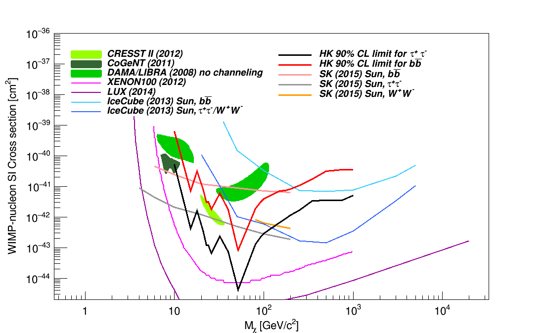
WIMPs bound in the halo of the galaxy may also become gravitationally trapped within the Earth (or sun) after losing energy via scattering processes with nuclei in its interior. If these then pair annihilate and produce neutrinos, they will escape the core of the Earth and be detectable at Hyper-Kamiokande. Assuming that the rate of WIMP capture within the sun is in equilibrium with the annihilation rate, measurements of the WIMP-induced neutrino flux can be directly translated into measurements of the WIMP-nucleon scattering cross section without the need to measure the self-annihilation cross section. Since the Earth is composed of heavy nuclei (relative to hydrogen) it is further possible to study WIMP interactions that are not coupled to the nuclear spin (spin independent, SI).
In the analysis below the local dark matter density is assumed to be 0.3 GeV/ with an RMS velocity of 270 km/s. The rotation of the solar system through the halo is taken to be 220 km/s. Signal MC has been generated by reweighting atmospheric neutrino MC events to spectra produced by the WIMPSIM package Blennow et al. (2008), which accounts for the passage of particles through terrestrial matter. Oscillation between flavors as the neutrinos travel from the Earth core to the detector are included. An independent set of atmospheric neutrino MC is used to model the background.
The search for WIMPs bound and annihilating at the center of the Earth proceeds along similar lines as the search for events from the galactic center, though events are now binned in momentum and , the zenith angle of the reconstructed lepton direction relative to Hyper-K. In these coordinates the atmospheric neutrino background takes its characteristic shape while the WIMP signal MC is peaked sharply in the direction of the Earth core; the most upward-going bin. Limits on the WIMP-induced neutrino flux are translated into limits on the WIMP-nucleon SI cross sections using the DarkSUSY simulation. Hyper-K’s sensitivity with a 1.9 Mtonyear exposure shown in Figure 193. The plot shows the sensitivity to the WIMP-nucleon SI cross section for masses compared to allowed regions (shown as hatched spaces) and limits (shown as lines) from current experiments. These limits have been produced assuming WIMPs have only SI interactions and have been estimated for and Hyper-K’s is expected to produce limits a factor of times stringent than Super-K if no WIMP signal is seen. Further, current hints for a positive SI dark matter signal Bernabei et al. (2008); Savage et al. (2009); Agnese et al. (2013); Angloher et al. (2012); Aalseth et al. (2011), can be probed completely by Hyper-K’s channel.
It is worth noting that in both the Earth and galactic center analyses no improvement in systematic errors beyond Super-K’s current understanding has been assumed. At Hyper-K the statistical uncertainty in the data is small enough that increases in sensitivity relative to Super-K is limited by systematic errors in the atmospheric neutrino flux and cross section model. Due to the relatively high energy of the signal events and the expected directional resolution of the detector, systematic errors in the detector response, while currently less well known, are expected to be less significant. While it is uncertain how the flux and cross section model will evolve in the future, improved modeling will translate directly into better sensitivity to WIMP-induced neutrinos at Hyper-K.
III.3.3 Other astrophysical neutrino sources
III.3.3.1 Solar flare
Solar flares are the most energetic bursts which occur in the solar surface. Explosive release of energy stored in solar magnetic fields is caused by magnetic reconnections, resulting in plasma heating, particle accelerations, and emission of synchrotron X-rays or charged particles from the solar surface. In a large flare, an energy of 1033 ergs is emitted over 10’s of minutes, and the accelerated protons can reach energies greater than 10 GeV. Such high energy protons can produce pions by nuclear interactions in the solar atmosphere. Evidence of such nuclear interactions in the solar atmosphere are obtained via observations of solar neutrons, 2.2 MeV gamma rays from neutron captures on protons, nuclear de-excitation gamma rays, and possible MeV gamma rays from neutral pion decays. Thus, it is likely that neutrinos are also emitted by the decay of mesons following interactions of accelerated particles. Detection of neutrinos from a solar flare was first discussed in 1970’s by R.Davis Davis (1986); Bahcall (1988), but no significant signal has yet been found Aglietta et al. (1991); Hirata et al. (1988). There have been some estimates of the number of neutrinos which could be observed by large water Cherenkov detectors Fargion and Di Giacomo (2009); Kocharov et al. (1991). According to Fargion and Di Giacomo (2009), about 6-7 neutrinos per tank will be observed at Hyper-Kamiokande during a solar flare as large as the one in 20 January 2005, although the expected numbers have large uncertainties. Therefore, regarding solar flares our first astrophysics goal is to discover solar flare neutrinos with Hyper-K. This will give us important information about the mechanism of the particle acceleration at work in solar flares.
III.3.3.2 Gamma-Ray Burst Jets and Newborn Pulsar Winds
Gamma-ray bursts (GRBs) are the most luminous astrophysical phenomena with the isotropically-equivalent gamma-ray luminosity, , which typically occur at cosmological distance. Prompt gamma rays are observed in the MeV range, and their spectra can be fitted by a smoothened broken power law Mészáros (2006). The prompt emission comes from a relativistic jet with the Lorentz factor of , which is presumably caused by a blackhole with an accretion disk or a fast-spinning, strongly-magnetized neutron star. Observed gamma-ray light curves are highly variable down to ms, suggesting unsteady outflows. However, GRB central engines and their radiation mechanism are still unknown, and GRBs have been one of the biggest mysteries in high-energy astrophysics.
Internal shocks are naturally expected for such unsteady jets, and the jet kinetic energy can be converted into radiation via shock dissipation. In the “classical” internal shock scenario Rees and Mészáros (1994), observed gamma rays are attributed to synchrotron emission from non-thermal electrons accelerated at internal shocks. It has been suggested that GRBs may also be responsible for ultrahigh-energy cosmic rays (CRs), and TeV-PeV neutrinos have been predicted as a smoking gun of CR acceleration in GRBs Waxman and Bahcall (1997). One of the key advantages in GRB neutrino searches is that atmospheric backgrounds can significantly be reduced thanks to space- and time-coincidence, but no high-energy neutrino signals correlated with GRBs have been found in any neutrino detector including Super-K Thrane et al. (2009) and IceCube Abbasi et al. (2012).
On the other hand, the recent theoretical and observational progress has suggested that the above classical scenario has troubles in explaining observational features such as the low-energy photon spectrum. Alternatively, the photospheric scenario, where prompt gamma rays are generated around or under the “photosphere” (where the Compton scattering optical depth is unity), has become more popular Thompson (1994); Mészáros and Rees (2000a); Rees and Mészáros (2005). Indeed, observations have indicated a thermal-like component in GRB spectra Ryde et al. (2011); Axelsson et al. (2012). Energy dissipation may be caused by inelastic nucleon-neutron collisions Bahcall and Mészáros (2000); Mészáros and Rees (2000b); Derishev et al. (1999), and neutrons can naturally be loaded by GRB central engines either blackhole-accretion-disk system or strongly-magnetized neutron star. Then, quasi-thermal GeV-TeV neutrino emission is an inevitable consequence of such inelastic nucleon-neutron collisions Murase et al. (2013). Since neutrinos easily leave the flow, predictions for these neutrinos are insensitive to details of gamma-ray spectra. Hyper-K will enable us to search these quasi-thermal GeV-TeV neutrinos from GRB jets, and it also has an advantage over IceCube (that is suitable for higher-energy - GeV neutrinos). The GeV-TeV neutrino detection is feasible if a GRB happens at Mpc, and successful detections should allow us to discriminate among prompt emission mechanisms and probe the jet composition, leading to a breakthrough in understanding GRB physics. However, GRBs are rare astrophysical phenomena, so we have little chance to expect such a nearby bright burst in the next 10-100 years. Much more promising targets as high-energy neutrino sources would be energetic supernovae driven by relativistic outflows Mészáros and Waxman (2001); Razzaque et al. (2004); Ando and Beacom (2005); Murase and Ioka (2013). A significant fraction of GRB jets may fail to puncture their progenitor star, and photon emission from the jets can easily be hidden. Indeed, theoretical studies revealed the existence of conditions for a jet to make a successful GRB. “Choked jets” or “failed GRBs” are naturally predicted when the jet luminosity is not sufficient or the jet duration is too short or the progenitor is too big. The choked jets can explain trans-relativistic supernovae or low-luminosity GRBs, which show intermediate features between GRBs and supernovae Soderberg et al. (2006).
The neutrino event rate expected in Hyper-K depends on the isotropically-equivalent dissipation energy , Lorentz factor , and distance . For , and Mpc, the characteristic energy of quasi-thermal GeV-TeV neutrinos is GeV Murase et al. (2013). The neutrino-nucleon cross section for the charged-current interaction at 1 GeV is (averaged over and ), so the effective area of Hyper-K is at 1 GeV. Then, Hyper-K will be able to detect signal events from such a jet-driven supernova. Successful detections enable us to probe jet physics that cannot be directly studied by electromagnetic observations. Neutrinos enable us to understand how jets are accelerated and what the jet composition is, and will give us crucial keys to the mysterious connection between GRBs and energetic supernovae Thompson et al. (2004). Also, in principle, matter effects in neutrino oscillation could be investigated Farzan and Smirnov (2008); Razzaque and Smirnov (2010). Moreover, we will able to study how CR acceleration operates in dense radiation environments inside a GRB progenitor star. Whether CRs are accelerated or not depends on properties of shocks. The conventional shock acceleration mechanism can effectively operate only if the shock is radiation-unmediated collisionless Murase and Ioka (2013). On the other hand, when the shock is mediated by radiation, the so-called neutron-proton-converter acceleration mechanism can work efficiently Derishev et al. (2003); Kashiyama et al. (2013), which boosts the energy of quasi-thermal neutrinos produced by nucleon-neutron collisions Murase et al. (2013).
As discussed above, relativistic outflows containing neutrons should naturally lead to GeV-TeV neutrino production, but the outflows do not have to be jets. Another interesting case may be realized when a supernova explosion leaves a fast-spinning neutron star. Neutrons are loaded in the proto-neutron star wind via neutrino heating. Around the base of the outflow, the particle density is so high that neutrons and ions are tightly coupled via elastic collisions. Neutrons should be accelerated together with ions as the Poynting-dominated pulsar wind is accelerated. Once the outflow becomes relativistic enough to exceed the pion-production threshold, inelastic collisions naturally occur as the main dissipation process of relativistic neutrons. The neutrons then interact with the material decelerated by the shock and possibly with the overlying stellar material, producing 0.1-1 GeV neutrinos Murase et al. (2014). Detecting this signal would probe the otherwise completely obscured process of jet acceleration and the physics of rotating and magnetized proto-neutron star birth during the core collapse of massive stars. Hyper-K may expect events for a core-collapse supernova at 10 kpc. In addition, Hyper-K could also allow us to see MeV neutrinos through the channel. However, detection of these lower energy neutrinos would be more difficult because of the smaller cross sections at lower energies and because the signal may be buried in the exponential tail of thermal MeV neutrinos from the proto-neutron star.
To detect high-energy neutrino signals from hidden GRB jets or newborn pulsar winds embedded in supernovae, it is crucial to reduce atmospheric backgrounds using space and time coincidence, so information at other wavelengths is relevant. The atmospheric neutrino background at GeV energies is for and for , respectively Honda et al. (2011). We may take the time window of s after the explosion time that is measurable with MeV neutrinos or possibly gravitational waves. The localization is possible by follow-up observations at x-ray, optical, and infrared bands. The atmospheric background flux in the typical angular and time window is , which can be low enough for a nearby supernova.
Note that it is critical to have large volume detectors for the purpose of detecting GeV-TeV neutrinos. The present Super-K and liquid scintillator detectors such as JUNO and RENO-50 are too small to detect high-energy signals from astrophysical objects especially if extragalactic, and much bigger detectors such as Hyper-K and PINGU are necessary to have a good chance to hunt high-energy neutrinos from GRBs and energetic supernovae. Because of the atmospheric background, sensitivities above GeV energies are typically essential but searches for neutrinos below GeV could also be useful for nearby events.
III.3.3.3 Neutrinos from gravitational-wave sources
100 years after the prediction by Einstein, gravitational waves (GWs) have been detected by advanced-LIGO in 2015 Abbott et al. (2016). This has allowed us to conduct multi-messenger observations of astrophysical objects via multiple signals, i.e., electromagnetic (EM) waves (from radio to gamma-rays), neutrinos (from MeV to PeV) and GWs (kHz). Some strong GW emitters are also expected to be strong sources of neutrinos, e.g. supernovae and gamma-ray bursts. The searches for neutrino counterparts to GW sources have been performed Adrián-Martínez et al. (2016), including a search done by Super-Kamiokande collaboration Abe et al. (2016c), but there has been no clear counterpart found. This is consistent with the theoretical prediction because these GW sources (GW150914 and GW151226) are binary black-hole mergers. Although binary black-hole mergers as GW sources are not expected to generate other detectable signals, the mergers that contain at least one neutron star (i.e. black hole-neutron star binary or neutron star-neutron star binary) could emit other signals, includeing erg of neutrinos Sekiguchi et al. (2011). Indeed, a number of EM counterparts associated with GW170817 (neutron-star binary merger) were detected, including GRB170817A Abbott et al. (2017a, b). A search for neutrinos by Super-Kamiokande was also reported Abe et al. (2018), which did not detect any coincident neutrino. Hyper-Kamiokande has the potential to detect thermal neutrinos from nearby (Mpc) neutron star meger events.
Depending on the event rates, these objects would contribute to the relic neutrino spectrum. The central engine of gamma-ray bursts are also candidates of strong emitters of neutrinos and GWs. It is evident that there are ultra-relativistic jets which are driven by the central engine. However, the mechanism that generates the jet is still unclear. If this jet is driven by neutrino annihilation, which is one of the promising scenarios, concurrent observations of neutrinos and GWs will be important probe of the very central part of the violent cosmic explosions at Hyper-Kamiokande era Suwa and Murase (2009).
III.3.4 Neutrino geophysics
The chemical composition of the Earth’s core is one of the most important properties of the planet’s interior, because it is deeply connected to not only the formation and evolution of the Earth Allègre et al. (1995) itself but also to the origin of the geomagnetic field Fearn and Loper (1981). While paleomagnetic evidence suggests that the geomagnetic field has existed for roughly three billion years, it is known that a core composed of iron alone could not sustain this magnetic field for more than 20,000 years. Explaining the continued generation of the geomagnetic field as well as its other properties requires knowledge of composition of the core matter. Based on seismic wave velocity measurements and the composition of primordial meteorites the composition of the core is presumed to be an iron-nickel alloy that additionally includes light elements, such as oxygen, sulfur, or silicon McDonough and Sun (1995). However, since no sample of the Earth’s mantle has even been acquired, let alone a sample of the core, the composition of the latter, particularly its light element a abundance, remains highly uncertain. Since the deepest wellbore to date has a depth of 14 km Popov et al. (1999), and the depth to the outer core is 2900 km it is unlikely that a core sample can be obtained within this century. As a result, addition methods of determining the chemical composition of the core are essential to understanding the Earth and its magnetic field.
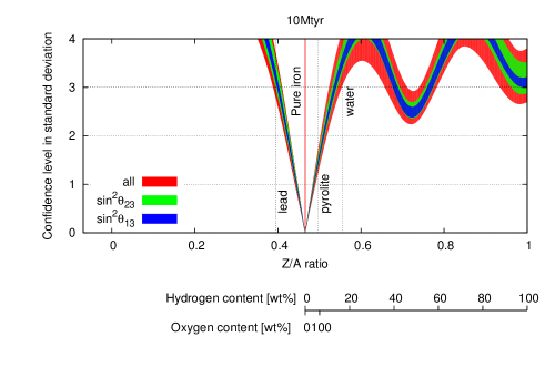
As discussed in Section III.1.2, the oscillation probability of atmospheric neutrinos depends on not only the various mixing angles, the neutrino mass differences, and CP-violating phase, , but also on the electron density of the media they traverse. This last property makes atmospheric neutrinos an ideal probe for measuring the electron density distribution of the Earth presuming the other oscillation parameters are well measured. Since accelerator neutrino measurements at Hyper-K itself are expected to dramatically improve on the precision of these parameters (c.f. Section III.1.1), Hyper-K may be able to make the first measurement of the core’s chemical composition using its atmospheric neutrino sample.
Hyper-K’s sensitivity in this regard has been studied in the context of atmospheric neutrino spectrum’s dependence upon the ratio of the proton to nucleon ratio (Z/A) of material in the outer core. Constraints from the combination of measurements of the Earth’s geodetic-astronomical parameters, such as its precession and nutation, with its low frequency seismic oscillation modes (free oscillations), and seismic wave velocity measurements have yielded precise knowledge of the planet’s density profile Dziewonski and Anderson (1981). Using this information the inner core and mantle layers of the Earth are fixed to pure iron (Z/A = 0.467) and pyrolite (Z/A = 0.496) and the Z/A value of the outer core is varied. The analysis uses the same analysis samples presented in Section III.1.2 and focuses on upward-going events between 1 and 10 GeV. Assuming the outer and inner core chemical compositions are the same, figure 194 shows the expected constraint on the Z/A parameter. After a 10 Mton year exposure Hyper-K can exclude lead and water (pyrolite) outer core hypotheses by approximately . While geophysics models will ultimately require even greater precision in such measurements, Hyper-K has the potential to make the spectroscopic measurements of the Earth’s core. It is worth noting that other proposed experiments with the ability to make similar geochemical measurements, such as the next generation of neutrino telescopes, rely primarily on the muon disappearance channel. Hyper-Kamiokande’s, on the other hand, is unique in that its sensitivity is derived from the electron appearance channel.
Part IV Second Detector in Korea
IV.1 Second Detector in Korea
IV.1.1 Motivations
Strategy of the future Hyper-K experiment is to build two identical water-Cherenkov detectors in stage with 260 kton of purified water per detector. The first detector will be built at Tochibora mine in Japan, and this Hyper-K design report is dedicated to describe the design of the first detector in Japan. Locations in Korea are currently investigated for the second detector where the J-PARC neutrino beam passes through, and this section focuses on the benefits of building the second detector in Korea. Figure 195 shows the J-PARC neutrino beam aiming at the Japanese site with 2.5 degree off-axis angle (OAA) and also passing through Korea with an 13 degree OAA range.
In fact, having a 2 detector regardless of its location, will improve sensitivities of all areas of physics covered by the Hyper-K 1 detector. However, building a 2 detector in Korea rather than in Japan further enhances physics capabilities on neutrino oscillation physics (leptonic CP violation, determination of neutrino mass ordering, non-standard neutrino interaction etc.) using beam neutrinos thanks to the longer baseline (1,100 km).
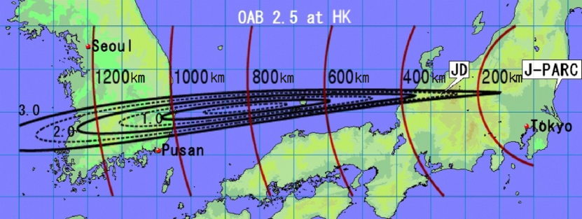
The benefits of Korean site for beam neutrino physics are well expressed by an appearance bi-probability plot: vs. . Figure 196 shows appearance bi-probability plots at Hyper-K sites in Tochibora, Japan (left) and in Mt. Bisul, Korea (right). Each point in colored ellipses represents different value for normal (inverted) neutrino mass ordering in solid (dotted) lines. Three different colors correspond to three representing neutrino energies for each site. The blue ellipses correspond to the peak energy at each OAA and the green and red ones represent median energy after splitting the events into two parts below and above the peak. Note that there are high energy ( 1.25 GeV) appearance events observed in Korean site due to the longer baseline, and this results in an important difference in physics sensitivities between Japan and Korean sites. The gray ellipses indicates the sizes of the statistical uncertainties given by from the number of events around peak energy in and appearance signals. It is clear from the bi-probability plots that the ellipses in Mt. Bisul site are well separated compare to those at Tochibora site although the statistics is lower with the longer distance. This will allow us to resolve degeneracies (overlaps of ellipses) in neutrino mass ordering and parameters.
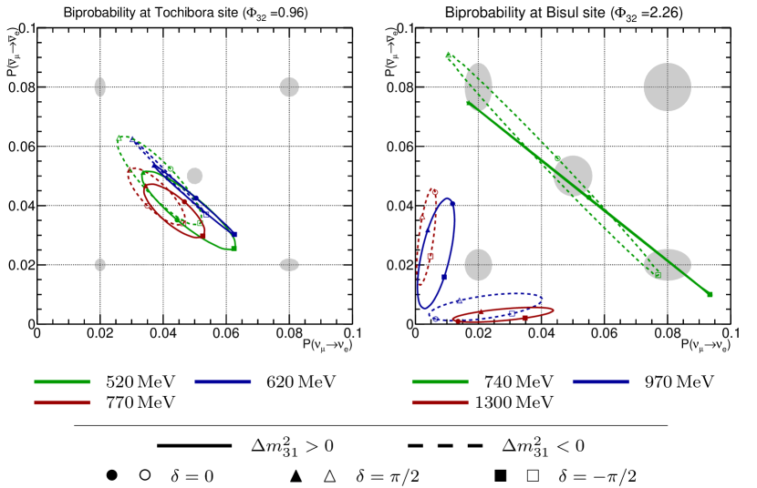
Thanks to the longer baselines in Korean sites the 1 and 2 oscillation maxima of the appearance probability are reachable with higher ( 1.25 GeV) neutrino energy, and this allows much better sensitivities especially on the neutrino mass ordering determination and non-standard neutrino interaction (NSI) in matter. By having the 2 detector in Korea the fraction of coverage is also increased and more precise measurement of is achieved. According to the sensitivity studies performed, described later, smaller OAA in Korean site gives best sensitivities in most physics cases with beam neutrinos. Reaching higher energy with smaller OAA, however, introduces more background but a good news is that T2K has recently reduced the background and its systematic uncertainty Abe et al. (2015c). Thanks to the larger overburdens in Korean sites the sensitivities on solar neutrino and Supernova relic neutrinos (SRN) are also further improved.
IV.1.2 Location and Detector
There are several candidate sites to locate the 2 detector in Korea and they are listed in Table 52. Among the six candidate sites Mt. Bisul with the smallest OAA seems to be the most favorite ones according to our sensitivity study described later.
| Site | Height | Baseline | Off-axis angle | Composition of rock |
|---|---|---|---|---|
| (m) | (km) | (degree) | ||
| Mt. Bisul | 1084 | 1088 | 1.3∘ | Granite porphyry, |
| andesitic breccia | ||||
| Mt. Hwangmae | 1113 | 1141 | 1.9∘ | Flake granite, |
| porphyritic gneiss | ||||
| Mt. Sambong | 1186 | 1169 | 2.1∘ | Porphyritic granite, |
| biotite gneiss | ||||
| Mt. Bohyun | 1124 | 1043 | 2.3∘ | Granite, volcanic rocks, |
| volcanic breccia | ||||
| Mt. Minjuji | 1242 | 1145 | 2.4∘ | Granite, biotite gneiss |
| Mt. Unjang | 1125 | 1190 | 2.2∘ | Rhyolite, granite porphyry, |
| quartz porphyry |
The larger overburdens of the Korean candidate sites allow much less muon flux and spallation isotopes. With a flat tunnel the overburden is 820 m for both Mt. Bisul and Mt. Bohyun, the two favorable sites in a more favorable order. By making a sloped tunnel the overburden becomes 1000 m for both mountains, and this is the default tunnel construction plan. Figure 197 shows muon flux as a function of zenith (top) and azimuth (bottom) angles for Mt. Bisul and Mt. Bohyun as well as Super-K and Hyper-K (Tochibora) sites for comparison. The muon flux at the two Korean sites with 1,000 m overburden are similar to that of Super-K site and about four times smaller than Hyper-K Tochibora site.
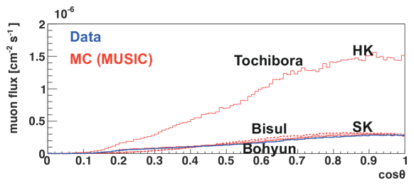
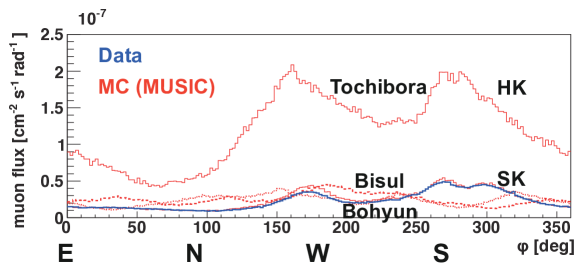
IV.1.3 Physics Sensitivities
Physics sensitivity studies are performed for three different off-axis angles (1.5∘, 2.0∘, and 2.5∘) at a baseline distance of km. Sensitivity study results are obtained for the determination of the mass ordering, the discovery of CP violation by excluding of the sin() = 0 hypothesis, the precision measurement of , fraction of as a function of CPV significance and exposure, octant, atmospheric parameters and NSI. Only part of these studies are shown here due to a limited space, but the full studies will be published in a separate paper. The results are obtained by assuming 2.71022 proton-on-target with which corresponds to 10-year operation with 1.3 MW beam power for 187 kton fiducial volume mass per detector. In this section relatively simplistic systematic uncertainty model Abe et al. (2016d) is used in the sensitivity studies while the size of the systematic uncertainties are mostly based on the current T2K analyses. Note that the same simplistic systematic uncertainty model is used for the Japanese detector, which is a little different from the systematic uncertainties used in other sections of this document. In sensitivity studies other oscillation parameter values are from the Particle Data Group (PDG) 2015 Review of Particle Physics Patrignani et al. (2016) except for and , where and eV2 are used due to their large uncertainties in their absolute values, and no CP violation ( = 0) is assumed unless it is specified. Two detector configuration, either JD (Japanese Detector) + KD (Korean Detector) or JD 2, assumes no staging in the sensitivity studies shown in this section.
Figure 198 shows the sensitivity on the 1 precision of the measurement assuming no prior knowledge on neutrino mass ordering. For most of the true the best sensitivity is from JD + KD with 1.5∘ OAA. Especially when the CP is maximally violated the sensitivity difference is largest between the JD + KD with 1.5∘ OAA and JD 2 or JD 1.
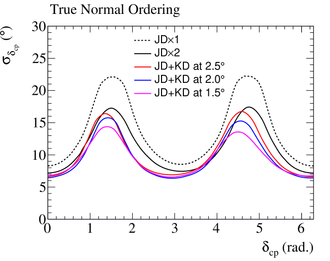
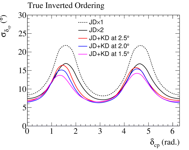
Figure 199 shows the sensitivity on the fraction of for the 1 precision of the measurement. The results with JD + KD with any off-axis angle are always better than JD 2 and JD 1. The sensitivity with 2.0∘ OAA is slightly better than that of 1.5∘ OAA if the precision is less than 10 degree but otherwise the 1.5∘ OAA gives the best sensitivity. More details on the physics sensitivity studies are found in Ref Abe et al. (2016d).
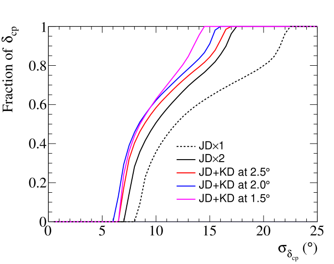
According to our sensitivity study CP violation sensitivity improves a little in JD + KD compared to JD 2. The octant sensitivity and atmospheric parameter sensitivities get slightly worse in JD + KD configuration compared to JD 2.
The sensitivity on NSI of neutrinos in matter (not in production nor in detection) is also greatly enhanced by having an additional 2 detector in Korea, and the details on NSI sensitivity studies are found in Ref S. Fukasawa and Yasuda (2017); Liao et al. (2017).
Thanks to the similar overburden to Super-K in Korean candidate sites (see Fig. 197) but with a larger detection volume, low energy astrophysics such as solar neutrinos and SRN sensitivities are expected to be good. According to our sensitivity study on the SRN we expect about 5 (4) sigma sensitivity for 10 years of data taking in Mt. Bisul or Mt. Bohyun (Tochibora) sites Yeum et al. (2017). Moreover we expect to observe spectral distribution of SRN due to large statistics from 8.4 times larger detection volume than Super-K, and this might lead to solving SN burst rate problem.
IV.1.4 Conclusion
Having a 2 Hyper-K detector in addition to the 1 one will enhance physics sensitivities from beam neutrino physics to astroparticle physics due to the increased detection volume. According to our sensitivity studies, physics capabilities of the Hyper-K project are further improved by locating the 2 detector in Korea, such as determination of neutrino mass ordering, precision of measurement and test of NSI. With the longer baseline in Korean site both the 1 and the 2 oscillation maximum of the appearance neutrino probability are reachable, and this is a unique opportunity since no other past and current experiment (MINOS, T2K, NOvA) can reach the 2 oscillation maxima. The longer baseline to the detector in Korea allows to resolve the degeneracy between the mass ordering and the value of delta CP that would happen for only certain values of the parameters with a detector(s) in Japan. The bi-probability plots can intuitively show this feature even before performing any sensitivity studies. NSI sensitivities are also improved especially with the smaller OAA site in Korea. According to our sensitivity studies the best Korean candidate site seems to be the Mt. Bisul. With 1000 m overburden sensitivities on solar neutrino and SRN physics are further enhanced in the Korean candidate sites than those in the Tochibora mine (650 m overburden).
Part V Appendix
Appendix A Liner Sheet Tests
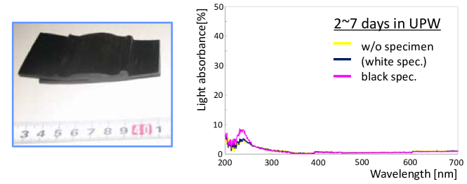
A.1 Immersion test
Specimens of HDPE lining sheet (GSE Gundle sheet, whose material is identical to that for the CPL), with artificial extrusion-welded seam, were immersed into the ultra-purified water (UPW) for certain periods (1, 2 to 7, and 8 to 31 days), and absorbance was compared to a control sample without specimens. Amount of eluted materials into UPW, i.e. total organic carbon (TOC), anions and metals, were also measured. Figure 200 show the specimen and an example of measurements, where increase of the light absorbance were observed between the wavelength range of 200300 nm. Some amount of material elution were observed, where eluted amounts per unit area and time were significantly less for later periods. Although relation between the increase of light absorbance and the material elusion should be studied, it is noted that range of PMT-sensitive wavelength is somewhat higher (300650 nm), so the effect to the experiment may be limited. Similar results were obtained for Gadolinium sulfate solutions.
A.2 Measurements on material strength
Tension tests were carried out for the CPL to estimate yield strength, tensile strength, and Young’s modulus. Since HDPE has large elongation before breaking (500%), 1.0% proof stress was used as the yield strength (instead of 0.2% proof stress which is generally used for other materials). Here, varying measurement conditions were examined for tensioning velocity (0.05 mm/min and 0.5 mm/min) and for temperature (typical room temperature 23.5∘ Celsius and 15∘ Celsius simulating water temperature). It was found that measured yield strengths were smaller by a few to several tens of percent than the specification value (15.2 MPa as listed in Table 11). In general, lower tensioning speed gives lower strength, due to large plasticity of HDPE. Strength also depends significantly on temperature: HDPE becomes harder with lowering temperature, as common properties in high-polymer materials. The measurement in 15∘ Celsius gave about 20% higher strengths than those at 23.5∘ Celsius. The tension tests were also repeated on the samples with an extrusion-welded seam. For the most cases, none of peeling, fracture, nor other troubles were observed on welded seams, but the deformation occurred at the base material. The yield/tensile strength were almost identical to the values for base material.
A.3 Creep test
Creep tests were performed with various tensile loads: 1/4M, 3/8M, or 1/2M, where M = 18.2 MPa is the observed yield strength as 1.0% proof stress with tensioning speed of 5.0 cm/min in 20∘ Celsius. For the tests with load of 1/4M (i.e. 4.6 MPa), creep was not observed for about 30 days. Meanwhile, for tests with load of 3/8M (6.8 MPa) and 1/2M (9.1 MPa), clear generation of creep was observed with 5 and 10 days, respectively.
A.4 Resistivity to localized water pressure
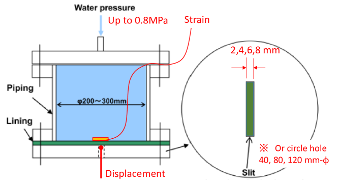
Ideally, the CPL sheet should be closely attached to the surface of flatly-backfilled concrete walls and thus firmly supported by them. However, it is probable that cracks or rough holes exist or happen in the backfill concrete wall, and thus the liner should locally stand for water pressure by itself. To simulate the situation, tests to apply localized water pressure for the lining were performed with variety of slit widths (2 to 8 mm) and hole diameters (40 to 120 mm-), as illustrated in Fig. 201. It is found that the liner survived for 0.8 MPa water pressure without breaking for all cases. Although the test load was applied only in a short period and durability for longer period should be examined, it is probable that the expected water pressure is enough lower than the critical pressure causing creep.
A.5 Water permeability
Generally, plastic materials have a property to pass water as moisture vapor through molecules. It is referred as moisture permeability, or water vapor transmission rate (WVTR), being represented with transferred mass through unit area and time (g/m2/24-hours). The permeability was studied for the GSE geomembrane (Gundle sheet, whose material is quite simmilar to that for CPL Studliner) Nakata et al. (2013). For the sheet with thickness = 1.5 mm, WVTR () was obtained to be 1 g/m2/24-hours at most for standard testing temperature (40∘ Celsius). The water permeability coefficient () was then deduced to be
where is standard gravitational acceleration (9.8 m2/s) and is difference of the water-vapor pressures of both sides of the geomembrane (90% of saturated vapor pressure at 40∘ Celsius, 75.22 hPa). Since the CPL is 5 mm thick, time until water permeates to backside of the CPL is:
i.e. about 6,300 years. Since the total inner surface area of the tank is 18,259 (54,750) m2 for 1 (3) tank options, amount of water permeation through the entire liner surface will be:
thus being negligible amount.
A.6 Penetration structure
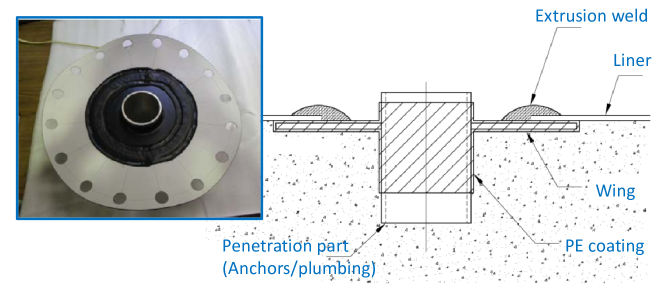
The leak can happen around the components which penetrate the water tank lining, such as anchors to support PMT framework columns, water supply/return pipes, and so on. A possible design of the penetration structure for the water pipes is illustrated in Fig. 202. A metal pipe with a flange is coated together with PE resin of about 1.5 mm thickness, which can be extrusion-welded to adjacent CPLs. A prototype was made for the design as shown together in the figure, and tested with pressure up to 1 MPa for 30 minutes. Tests with cyclic pressure (0.5 MPa, repeating on/off in a day for 5 days) and with continuous pressure (3 months with applying 0.5 MPa were also performed. For all of the cases, no water leak was observed.
Appendix B Hakamagoshi Option
The area around Mount Hakamagoshi in Toyama Prefucture’s Minami-Tonami is being considered as a possible candidate for the second Hyper-K tank. Lying nearly along an extension of the line between Tokai-mura and Super-Kamiokande Mount Hakamagoshi can observe neutrinos from the J-PARC beam in the same way as the detector in Kamioka. Though a detailed survey of the rock quality in the area is still needed, the 1000 m height of the peaks suggest that high-quality stable rock can be expected. A detector at Hakamagoshi would have an overburden of more than 1 km and would therefore be well suited to the observation of low energy neutrinos such as those from supernovae and the sun. Further, since the Tokai-Hokuriku expressway passes through the mountain, access to the experimental site is straight-forward.
B.1 Rock Quality Information for Hakamagoshi and its Surroundings
The Hakamagoshi area is characterized by Mount Hakamagoshi (elev. 1,159 m), Mount Mikata (elev. 1,142 m), and Mount Sarugayama (elev. 1,448 m), which form a mountain chain running from northeast to southwest. Mountain streams along the north side of these peaks form part of the Oyabegawa river system, while similar streams on the southern side running to the east and south form the network of waterways feeding the Shogawa river. In short, the area around Hakamagoshi is the watershed for the Oyabegawa and Shogawa rivers, which is a strong indicator of abundant underground water. Indeed, measurements have yielded spring water flows in excess of 100 tons per hour. Hakamagoshi and its surroundings are formed from the primary Futomiyama formation (from the Paloegene-Paleocene), sporadically covered with so-called Hida bedrock (a mixture of Shirakawa granite and Nohi ryolite). The rock types in the Futomiyama formation as it is distributed throughout Hakamagoshi are primarily ryholitic tuff, ryholitic welded tuff, and ryholitic lava. In addition, quartz porphyry, porphyrite, dorelite and other rock intrusions of no known era are found within the formation. The upper layers of the formation are inconsistently covered by Tori conglomerate from the Neogene-Miocene eras. In particular this conglomerate is found above the Hakamagoshi tunnel at elevations around 900 m. The upper most layers are composed of andesite and andesitic pyroclast from the same eras. On site investigations of the lithic fragments from the Futomiyama formation indicate large amounts of CHCM class hardness rock.
Figure 203 shows the rock quality distribution around Hakamagoshi in hardness classes. In the lower layers of the Futomiyama formation Shogawa granodiorite is widespread, and in addition to this formation, at 1000 m depths other distributions of Shogawa granodiorite and Kose diorite may be found. Since it is generally thought that diorite layers are higher quality in comparison to the Futomiyama formation, the key to realizing the Hakamagoshi option lies in determining whether or not such layers exist at the site.
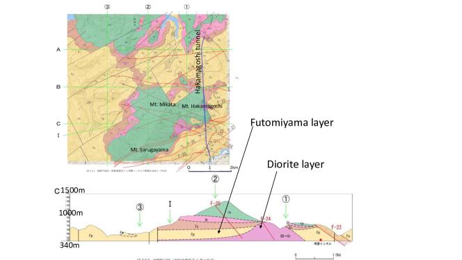
B.2 Physics sensitivities
B.2.1 Muon rate at Mt. Hakamagoshi
For the moment we assume that a detector is placed directly beneath the peak of Mount Hakamagoshi at the same level as the expressway tunnel and calculate the expected muon rate. In order to study the reliability of these estimates the calculation is additionally performed for the area inside of the tunnel and then compared with measurements made with a plastic scintillator-based detector. The estimation uses 30 m elevation data from the ALOS database in the same way as calculations performed for the Tochibora site. MUSIC and FLUKA are used for the muon simulation. With a peak elevation of 1,159 m and a tunnel elevation of approximately 300 m, here the rock overburden is taken to be roughly 850 m. Similarly the rock density is assumed to be the same as in Kamioka, 2.7 g/. Figure 204 shows zenith, azimuthal, and energy distributions from the simulation. Comparing to the Tochibora site, the muon rate at the Hakamagoshi site is roughly a factor of two times smaller and the mean muon energy is reduced by about 10%. The following sensitivity studies have been performed based on these results.
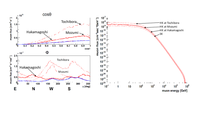
To validate the results of these simulations the muon rate inside the Hakamagoshi tunnel was measured in cooperation with NEXCO Central Nippon in an air conditioning chamber from January 18-20, 2016. This chamber is not located beneath the mountain peak and has an overburden of only 450 m. Two plastic scintillators of dimension and separated by 100 mm were used for coincident muon identification. For comparison the same measurement was repeated at the Super-Kamiokande experimental site. Using this apparatus the muon rates were measured to be Hz and Hz at the Hakamagoshi and Super-K sites, respectively. That is, the air conditioning chamber’s muon rate is times larger. Based on the simulations outlined above the expected difference is a factor of 8.9, indicating that the data and simulation are consistent within errors. For this reason the simulation of the Hakamagoshi site below the mountain peak is taken to be reasonable.
B.2.2 Neutrino beam from J-PARC
In the following the Hakamakoshi detector is assumed to be beneath the peak of the mountain, as in the simulations above, and the sensitivity neutrino oscillations using the J-PARC neutrino beam is estimated. Hakamagoshi has an off-axis angle of and a baseline of 335 km. The corresponding flux and oscillation probabilities are shown in Figure 205. Since the off-axis angle is sightly smaller than that for the Tochibora site, the flux peak has shifted to slightly higher energies, but since the baseline is correspondingly larger the oscillation maximum is found at nearly the same energy. Using this information the sensitivity to CP violation has been estimated as shown in Figure 206. Here the first tank is assumed to be located in Tochibora with the second tank beginning operations six years later. A comparison is made between a second tank in Tochibora and one in Hakamagoshi. Due to the larger baseline to Hakamagoshi there is a corresponding decrease in event rate, resulting in a slightly larger statistical error, though the systematic errors are taken to be the same.
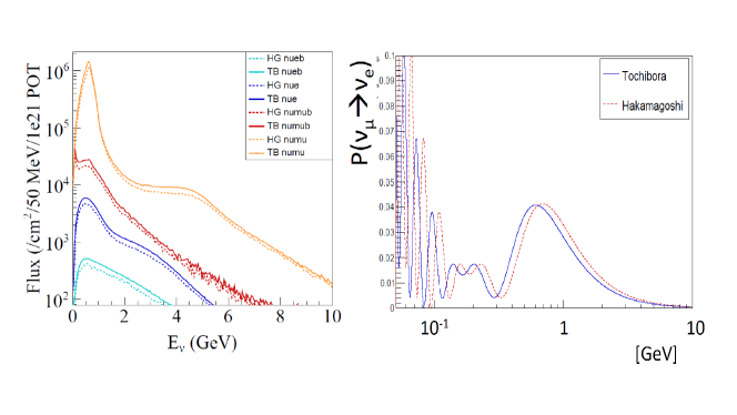
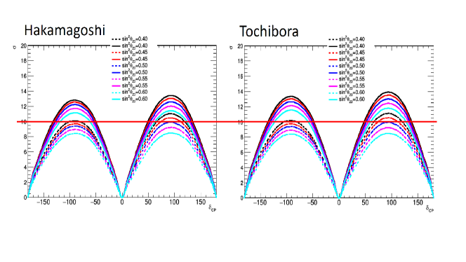
B.2.3 Low Energy Neutrino Observations
Spallation products from cosmic ray muons form the main background to low energy neutrino physics in Hyper-K, including supernova and solar neutrino measurements. Since the muon background at Hakamagoshi is lower than that at Tochibora, the former is expected to have improved sensitivity to these neutrinos. Using the muon simulation results presented above to derive the spallation backgrounds, Hyper-K’s sensitivity to the observation of supernova relic neutrinos has been estimated. In this analysis an analysis sample selected using neutron tagging (70% tagging efficiency) to identify the inverse beta decay signal in an energy window of 16 to 30 MeV has been assumed. Figure 207 shows the expected sensitivity assuming only one tank at at the Hakamagoshi site. Assuming a standard model of the relic neutrino flux and the first detector in Tochibora, the signal can be observed with () significance after 4 (11) years.
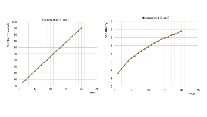
References
- Aad et al. (2013) G. Aad et al. (ATLAS), Phys. Lett. B716, 1 (2013), arXiv:1207.7214 [hep-ex] .
- Chatrchyan et al. (2012) S. Chatrchyan et al. (CMS), Phys. Lett. B716, 30 (2012), arXiv:1207.7235 [hep-ex] .
- Fukuda et al. (1998) Y. Fukuda et al. (Super-Kamiokande), Phys. Rev. Lett. 81, 1562 (1998), arXiv:hep-ex/9807003 .
- Maki et al. (1962) Z. Maki, M. Nakagawa, and S. Sakata, Prog. Theor. Phys. 28, 870 (1962).
- Pontecorvo (1968) B. Pontecorvo, Sov. Phys. JETP 26, 984 (1968).
- Olive et al. (2014) K. A. Olive et al. (Particle Data Group), Chin. Phys. C38, 090001 (2014).
- Kobayashi and Maskawa (1973) M. Kobayashi and T. Maskawa, Prog. Theor. Phys. 49, 652 (1973).
- Schechter and Valle (1980) J. Schechter and J. W. F. Valle, Phys. Rev. D22, 2227 (1980).
- Bilenky et al. (1980) S. M. Bilenky, J. Hosek, and S. T. Petcov, Phys. Lett. B94, 495 (1980).
- Doi et al. (1981) M. Doi, T. Kotani, H. Nishiura, K. Okuda, and E. Takasugi, Phys. Lett. B102, 323 (1981).
- Ahmad et al. (2002) Q. R. Ahmad et al. (SNO), Phys. Rev. Lett. 89, 011301 (2002), arXiv:nucl-ex/0204008 [nucl-ex] .
- Ahmad et al. (2001) Q. R. Ahmad et al. (SNO), Phys. Rev. Lett. 87, 071301 (2001), arXiv:nucl-ex/0106015 [nucl-ex] .
- Abe et al. (2011a) K. Abe et al. (Super-Kamiokande), Phys. Rev. D83, 052010 (2011a), arXiv:1010.0118 [hep-ex] .
- Eguchi et al. (2003) K. Eguchi et al. (KamLAND), Phys. Rev. Lett. 90, 021802 (2003), arXiv:hep-ex/0212021 [hep-ex] .
- Araki et al. (2005) T. Araki et al. (KamLAND), Phys. Rev. Lett. 94, 081801 (2005), arXiv:hep-ex/0406035 [hep-ex] .
- Abe et al. (2008) S. Abe et al. (KamLAND), Phys. Rev. Lett. 100, 221803 (2008), arXiv:0801.4589 [hep-ex] .
- Ashie et al. (2005) Y. Ashie et al. (Super-Kamiokande), Phys. Rev. D71, 112005 (2005), arXiv:hep-ex/0501064 .
- Ashie et al. (2004) Y. Ashie et al. (Super-Kamiokande), Phys. Rev. Lett. 93, 101801 (2004), arXiv:hep-ex/0404034 .
- Ahn et al. (2006) M. H. Ahn et al. (K2K), Phys. Rev. D74, 072003 (2006), arXiv:hep-ex/0606032 .
- Adamson et al. (2011a) P. Adamson et al. (MINOS), Phys. Rev. Lett. 106, 181801 (2011a), arXiv:1103.0340 [hep-ex] .
- Abe et al. (2012a) K. Abe et al. (T2K), Phys. Rev. D85, 031103 (2012a), arXiv:1201.1386 [hep-ex] .
- Abe et al. (2014a) K. Abe et al. (T2K Collaboration), Phys. Rev. Lett. 112, 181801 (2014a), arXiv:1403.1532 [hep-ex] .
- Abe et al. (2011b) K. Abe et al. (T2K), Phys. Rev. Lett. 107, 041801 (2011b), arXiv:1106.2822 [hep-ex] .
- Adamson et al. (2011b) P. Adamson et al. (MINOS), Phys. Rev. Lett. 107, 181802 (2011b), arXiv:1108.0015 [hep-ex] .
- Abe et al. (2013a) K. Abe et al. (T2K), Phys.Rev. D88, 032002 (2013a), arXiv:1304.0841 [hep-ex] .
- Abe et al. (2014b) K. Abe et al. (T2K Collaboration), Phys. Rev. Lett. 112, 061802 (2014b), arXiv:1311.4750 [hep-ex] .
- Abe et al. (2012b) Y. Abe et al. (Double Chooz), Phys. Rev. Lett. 108, 131801 (2012b), arXiv:1112.6353 [hep-ex] .
- Ahn et al. (2012) J. K. Ahn et al. (RENO), Phys. Rev. Lett. 108, 191802 (2012), arXiv:1204.0626 [hep-ex] .
- An et al. (2012) F. P. An et al. (Daya Bay), Phys. Rev. Lett. 108, 171803 (2012), arXiv:1203.1669 [hep-ex] .
- An et al. (2014) F. P. An et al. (Daya Bay), Phys. Rev. Lett. 112, 061801 (2014), arXiv:1310.6732 [hep-ex] .
- Abe et al. (2014c) Y. Abe et al. (Double Chooz), Phys. Lett. B735, 51 (2014c), arXiv:1401.5981 [hep-ex] .
- Abe et al. (2015a) K. Abe et al. (Super-Kamiokande), Phys. Rev. D91, 052019 (2015a), arXiv:1410.2008 [hep-ex] .
- Mitsuka et al. (2011) G. Mitsuka et al. (Super-Kamiokande), Phys. Rev. D84, 113008 (2011), arXiv:1109.1889 [hep-ex] .
- Abe et al. (2015b) K. Abe et al. (Super-Kamiokande), Phys. Rev. D91, 052003 (2015b), arXiv:1410.4267 [hep-ex] .
- Mohapatra and Smirnov (2006) R. Mohapatra and A. Smirnov, Ann. Rev. Nucl. Part. Sci. 56, 569 (2006), arXiv:hep-ph/0603118 [hep-ph] .
- Mikheev and Smirnov (1985) S. P. Mikheev and A. Yu. Smirnov, Sov. J. Nucl. Phys. 42, 913 (1985), [Yad. Fiz.42,1441(1985)].
- Wolfenstein (1978) L. Wolfenstein, Phys. Rev. D17, 2369 (1978).
- Petcov and Piai (2002) S. T. Petcov and M. Piai, Phys. Lett. B533, 94 (2002), arXiv:hep-ph/0112074 [hep-ph] .
- An et al. (2015) F. An et al. (JUNO), (2015), arXiv:1507.05613 [physics.ins-det] .
- Kim (2014) S.-B. Kim, in Neutrino Oscillation Workshop (NOW 2014) Conca Specchiulla, Otranto, Lecce, Italy, September 7-14, 2014 (2014) arXiv:1412.2199 [hep-ex] .
- de Gouvea et al. (2005) A. de Gouvea, J. Jenkins, and B. Kayser, Phys. Rev. D71, 113009 (2005), arXiv:hep-ph/0503079 [hep-ph] .
- Nunokawa et al. (2005) H. Nunokawa, S. J. Parke, and R. Zukanovich Funchal, Phys. Rev. D72, 013009 (2005), arXiv:hep-ph/0503283 [hep-ph] .
- Guo et al. (2007) X. Guo et al. (Daya-Bay), (2007), arXiv:hep-ex/0701029 .
- Ahn et al. (2010) J. K. Ahn et al. (RENO), (2010), arXiv:1003.1391 [hep-ex] .
- Ardellier et al. (2006) F. Ardellier et al. (Double Chooz), (2006), arXiv:hep-ex/0606025 .
- Ahmed et al. (2015) S. Ahmed et al. (ICAL), (2015), arXiv:1505.07380 [physics.ins-det] .
- Aartsen et al. (2014) M. G. Aartsen et al. (IceCube PINGU), (2014), arXiv:1401.2046 [physics.ins-det] .
- Katz (2014) U. F. Katz (KM3NeT), in Proceedings of the 15th International Workshop on Neutrino Telescopes (Neutel 2013) (2014) arXiv:1402.1022 [astro-ph.IM] .
- Barger et al. (1980) V. D. Barger, K. Whisnant, and R. J. N. Phillips, Phys. Rev. Lett. 45, 2084 (1980).
- Pakvasa (1980) S. Pakvasa, Proceedings, 20th International Conference on High-Energy Physics, AIP Conf. Proc. 68, 1164 (1980).
- Abe et al. (2015c) K. Abe et al. (T2K), Phys. Rev. D91, 072010 (2015c), arXiv:1502.01550 [hep-ex] .
- (52) M. Sanchez, “Results and Prospects from the NOvA Experiment,” Talk presented at the XVII International Workshop on Neutrino Factories and Future Neutrino Facilities (NuFact15), Rio de Janeiro, Brazil, August. 2015.
- Wendell (2015) R. Wendell (Super-Kamiokande), Proceedings, 26th International Conference on Neutrino Physics and Astrophysics (Neutrino 2014), AIP Conf. Proc. 1666, 100001 (2015), arXiv:1412.5234 [hep-ex] .
- Renshaw et al. (2014) A. Renshaw et al. (Super-Kamiokande), Phys. Rev. Lett. 112, 091805 (2014).
- Mikheyev and Smirnov (1985) S. P. Mikheyev and A. Y. Smirnov, Yad. Fiz. 42, 1441 (1985).
- Mikheyev and Smirnov (1986) S. P. Mikheyev and A. Y. Smirnov, Nuov. Cim. C9, 17 (1986).
- Bruenn et al. (2013) S. W. Bruenn, A. Mezzacappa, W. R. Hix, E. J. Lentz, O. E. B. Messer, E. J. Lingerfelt, J. M. Blondin, E. Endeve, P. Marronetti, and K. N. Yakunin, The Astrophysical Journal Letters 767, L6 (2013), arXiv:1212.1747 [astro-ph.SR] .
- Melson et al. (2015) T. Melson, H.-T. Janka, and A. Marek, The Astrophysical Journal Letters 801, L24 (2015), arXiv:1501.01961 [astro-ph.SR] .
- Lentz et al. (2015) E. J. Lentz, S. W. Bruenn, W. R. Hix, A. Mezzacappa, O. E. B. Messer, E. Endeve, J. M. Blondin, J. A. Harris, P. Marronetti, and K. N. Yakunin, The Astrophysical Journal Letters 807, L31 (2015), arXiv:1505.05110 [astro-ph.SR] .
- Takiwaki et al. (2014) T. Takiwaki, K. Kotake, and Y. Suwa, The Astrophysical Journal 786, 83 (2014), arXiv:1308.5755 [astro-ph.SR] .
- Couch and O’Connor (2014) S. M. Couch and E. P. O’Connor, The Astrophysical Journal 785, 123 (2014), arXiv:1310.5728 [astro-ph.HE] .
- Tamborra et al. (2013) I. Tamborra, F. Hanke, B. Müller, H.-T. Janka, and G. Raffelt, Physical Review Letters 111, 121104 (2013), arXiv:1307.7936 [astro-ph.SR] .
- O’Connor and Ott (2013) E. O’Connor and C. D. Ott, The Astrophysical Journal 762, 126 (2013), arXiv:1207.1100 [astro-ph.HE] .
- Ando et al. (2005) S. Ando, J. F. Beacom, and H. Yüksel, Phys. Rev. Lett. 95, 171101 (2005), arXiv:astro-ph/0503321 .
- (65) http://lbne.fnal.gov/, LBNE collaboration.
- JPA (2003) “J-PARC TDR,” (2003), KEK Report 2002-13 and JAERI-Tech 2003-44.
- Beavis et al. (1995a) D. Beavis et al. (E889), “Long baseline neutrino oscillation experiment at the ags,” (1995a), BNL-52459 .
- Abe et al. (2013b) K. Abe et al. (T2K), Phys. Rev. D87, 012001 (2013b), [Addendum: Phys. Rev.D87,no.1,019902(2013)], arXiv:1211.0469 [hep-ex] .
- Abgrall et al. (2014) N. Abgrall et al. (NA61), JINST 9, P06005 (2014), arXiv:1401.4699 [physics.ins-det] .
- Abgrall et al. (2011a) N. Abgrall et al. (NA61/SHINE), Phys. Rev. C84, 034604 (2011a), arXiv:1102.0983 [hep-ex] .
- Abgrall et al. (2012) N. Abgrall et al. (NA61/SHINE), Phys. Rev. C85, 035210 (2012), arXiv:1112.0150 [hep-ex] .
- Abgrall et al. (2013) N. Abgrall et al. (NA61/SHINE), Nucl. Instrum. Meth. A701, 99 (2013), arXiv:1207.2114 [hep-ex] .
- Haesler (2015) A. Haesler, T2K Replica Target Hadron Production Measurements in NA61/SHINE and T2K Neutrino Flux Predictions, Ph.D. thesis, Geneva, University of Geneva (2015), presented 22 Jun 2015.
- Otani et al. (2010) M. Otani et al., Technology and instrumentation in particle physics. Proceedings, 1st International Conference, TIPP09, Tsukuba, Japan, March 12-17, 2009, Nucl. Instrum. Meth. A623, 368 (2010).
- Assylbekov et al. (2012) S. Assylbekov et al., Nucl. Instrum. Meth. A686, 48 (2012), arXiv:1111.5030 [physics.ins-det] .
- Allan et al. (2013) D. Allan et al. (T2K UK), JINST 8, P10019 (2013), arXiv:1308.3445 [physics.ins-det] .
- Aoki et al. (2013) S. Aoki et al., Nucl. Instrum. Meth. A698, 135 (2013), arXiv:1206.3553 [physics.ins-det] .
- Amaudruz et al. (2012) P. A. Amaudruz et al. (T2K ND280 FGD), Nucl. Instrum. Meth. A696, 1 (2012), arXiv:1204.3666 [physics.ins-det] .
- Abgrall et al. (2011b) N. Abgrall et al. (T2K ND280 TPC), Nucl. Instrum. Meth. A637, 25 (2011b), arXiv:1012.0865 [physics.ins-det] .
- Koseki (2014) T. Koseki, “J-PARC Accelerator: status, capacity and future plan,” (2014), Talk presented at the 2nd international symposium on science at J-PARC (J-PARC 2014), Tsukuba, Japan.
- Koseki (2015) T. Koseki, “J-PARC Accelerator: achievement and future upgrade,” (2015), Talk presented at the Workshop for Neutrino Programs with Facilities in Japan, August 4, 2015 Tokai, Japan.
- Kobayashi (2015) T. Kobayashi, “Potential J-PARC beam power improvement and beam delivery before 2026,” (2015), Talk presented at the Workshop for Neutrino Programs with Facilities in Japan, August 4, 2015 Tokai, Japan.
- (83) S. Igarashi, H. Harada, H. Hotchi, T. Koseki, and Y. Sato (2014), “Accelerator Concepts for the Beam Power of Multi MW with J-PARC MR,” Talk presented at the 2nd international symposium on science at J-PARC (J-PARC 2014), Tsukuba, Japan.
- Abe et al. (2011c) K. Abe et al. (T2K Collaboration), Nucl. Instrum. Meth. A659, 106 (2011c).
- Beavis et al. (1995b) D. Beavis, A. Carroll, I. Chiang, et al., (1995b), Long Baseline Neutrino Oscillation Experiment at the AGS(Proposal E889), Physics Design Report, BNL-52459.
- Yamada (2014) Y. Yamada (J-PARC neutrino beamline group), “J-PARC Neutrino beamline, present limits on beam power,” (2014), Talk presented at the 1st workshop on next generation accelerator-based neutrino experiment, Tokai, Japan, Feb. 2014.
- Tada (2014) M. Tada (J-PARC neutrino beamline group), “Neutrino beamline for multiple MW beam,” (2014), Talk presented at the 1st workshop on next generation accelerator-based neutrino experiment, Tokai, Japan, Feb. 2014.
- Martini et al. (2012) M. Martini, M. Ericson, and G. Chanfray, Phys. Rev. D85, 093012 (2012), arXiv:1202.4745 [hep-ph] .
- Lalakulich et al. (2012) O. Lalakulich, U. Mosel, and K. Gallmeister, Phys. Rev. C86, 054606 (2012), arXiv:1208.3678 [nucl-th] .
- Martini et al. (2013) M. Martini, M. Ericson, and G. Chanfray, Phys. Rev. D87, 013009 (2013), arXiv:1211.1523 [hep-ph] .
- Abe et al. (2017a) K. Abe et al. (T2K Collaboration), Phys. Rev. Lett. 118, 151801 (2017a).
- Abe et al. (2017b) K. Abe et al. (T2K Collaboration), (2017b), arXiv:1704.06409 [hep-ex] .
- Abe et al. (2016a) K. Abe et al. (T2K), Phys. Rev. D93, 112012 (2016a), arXiv:1602.03652 [hep-ex] .
- Coloma et al. (2014) P. Coloma, P. Huber, C.-M. Jen, and C. Mariani, Phys. Rev. D89, 073015 (2014), arXiv:1311.4506 [hep-ph] .
- Asfandiyarov et al. (2014) R. Asfandiyarov et al., (2014), arXiv:1405.6089 [physics.ins-det] .
- Bonnemaison et al. (2014) A. Bonnemaison et al., “A test experiment to develop a 3D grid-like neutrino detector with a water target for measurement of neutrino cross sections at the near detector hall of J-PARC neutrino beam-line,” (2014), Proposal to the J-PARC PAC.
- Abe et al. (2014d) K. Abe et al. (T2K), Phys. Rev. D90, 052010 (2014d), arXiv:1407.4256 [hep-ex] .
- Stahl et al. (2012) A. Stahl et al., “Expression of Interest for a very long baseline neutrino oscillation experiment (LBNO),” (2012), cERN-SPSC-2012-021, SPSC-EOI-007.
- Fukuda et al. (2014) T. Fukuda et al., JINST 9, P12017 (2014), arXiv:1412.4955 [physics.ins-det] .
- Kearns et al. (2005) E. Kearns et al., “A Proposal for a Detector 2 km Away From the T2K Neutrino Source,” (2005), accessed at: http://www.phy.duke.edu/ cwalter/nusag-members/2km-proposal-05-05-30.pdf, 10-2015.
- Aguilar-Arevalo et al. (2009) A. A. Aguilar-Arevalo et al. (MiniBooNE), Nucl. Instrum. Meth. A599, 28 (2009), arXiv:0806.4201 [hep-ex] .
- Bhadra et al. (2014) S. Bhadra et al. (nuPRISM), (2014), arXiv:1412.3086 [physics.ins-det] .
- Aguilar-Arevalo et al. (2001) A. Aguilar-Arevalo et al. (LSND), Phys. Rev. D64, 112007 (2001), arXiv:hep-ex/0104049 [hep-ex] .
- Aguilar-Arevalo et al. (2013) A. Aguilar-Arevalo et al. (MiniBooNE), Phys.Rev.Lett. 110, 161801 (2013), arXiv:1207.4809 [hep-ex] .
- Bhadra et al. (2015) S. Bhadra et al., “Proposal for the NuPRISM Experiment in the J-PARC Neutrino Beamline,” (2015), Proposal to the J-PARC PAC.
- Watanabe et al. (2009) H. Watanabe et al. (Super-Kamiokande), Astropart. Phys. 31, 320 (2009), arXiv:0811.0735 [hep-ex] .
- Alonso et al. (2014) J. Alonso, N. Barros, M. Bergevin, A. Bernstein, L. Bignell, et al., (2014), arXiv:1409.5864 [physics.ins-det] .
- Acciarri et al. (2014) R. Acciarri et al. (ArgoNeuT), Phys.Rev. D90, 012008 (2014), arXiv:1405.4261 [nucl-ex] .
- Mosel et al. (2014) U. Mosel, O. Lalakulich, and K. Gallmeister, Phys.Rev.Lett. 112, 151802 (2014), arXiv:1311.7288 [nucl-th] .
- Abe et al. (2014e) K. Abe et al. (Hyper-Kamiokande Working Group), (2014e), arXiv:1412.4673 [physics.ins-det] .
- (111) “Titus: the tokai intermediate tank for the unoscillated spectrum,” To be published (2015).
- Anghel et al. (2015) I. Anghel et al. (ANNIE), (2015), arXiv:1504.01480 [physics.ins-det] .
- Galbiati and Beacom (2005) C. Galbiati and J. F. Beacom, Phys. Rev. C72, 025807 (2005), [Erratum: Phys. Rev.C73,049906(2006)], arXiv:hep-ph/0504227 [hep-ph] .
- Suzuki et al. (1993) A. Suzuki, M. Mori, K. Kaneyuki, T. Tanimori, J. Takeuchi, H. Kyushima, and Y. Ohashi, Nucl. Instrum. Meth. A329, 299 (1993).
- Fukugita and Suzuki (1994) M. Fukugita and A. Suzuki, eds., Physics and astrophysics of neutrinos (1994).
- Fukuda et al. (2003) Y. Fukuda, T. Hayakawa, E. Ichihara, M. Ishitsuka, Y. Itow, et al., Nucl. Instrum. Meth. A501, 418 (2003).
- Abe et al. (2014f) K. Abe et al., Nucl. Instrum. Meth. A737, 253 (2014f), arXiv:1307.0162 [physics.ins-det] .
- Tanaka (1964) H. Tanaka, Introduction to Geology for Civil Engineers (in Japanese) (Sankaido, Tokyo, 1964).
- Hoek and Brown (1997) E. Hoek and E. T. Brown, Int. J. Rock Mech. Min. Sci. Vol.34, No.8, 1165 (1997).
- Hoek et al. (1995) E. Hoek, P. K. Kaiser, and W. Banden, Support of underground excavations in hard rock (Balkema, Rotterdam, 1995) p. 215.
- Hoek et al. (2002) E. Hoek, C. Carranza-Torres, and B. Corkum, in 2002 Edition, Proceedings of the 5th North American Rock Mechanics Symposium and the 17th Tunnelling Association of Canada Conference (MARMS-TAC, Toronto, Canada, 2002) pp. 267–273.
- Concrete Committee (2012) J. S. o. C. E. Concrete Committee, Standard Specifications for Concrete Structure (JSCE, Tokyo, 2012) p. 613.
- Becker-Szendy et al. (1993) R. Becker-Szendy et al., Nucl. Instrum. Meth. A324, 363 (1993).
- Inc (2011) G. A. Inc, “4850 LBNE water cherenkov detector (WCD) conceptual liner design option,” (2011), .
- Association (2010) J. W. M. Association, “Planning, design, and management of industrial waste final disposal site,” (2010), .
- Koerner et al. (2005) R. M. Koerner, Y. G. Hsuan, and G. R. Koerner, GRI White Paper No.6 (2005).
- Babson et al. (1990) J. Babson et al. (DUMAND Collaboration), Phys. Rev. D 42, 3613 (1990).
- Belolaptikov et al. (1997) I. A. Belolaptikov et al., Astropart. Phys. 7(3), 263 (1997).
- Rapidis et al. (2009) P. Rapidis et al. (NESTOR Collaboration), Nucl. Instrum. Meth. A602, 54 (2009).
- E.G.Anassontzis et al. (2002) E.G.Anassontzis et al. (NESTOR Collaboration), Nucl. Instrum. Meth. A479, 439 (2002).
- Ageron et al. (2011) M. Ageron et al. (ANTARES Collaboration), Nucl. Instrum. Meth. A656, 11 (2011).
- Amram et al. (2002) P. Amram et al. (ANTARES Collaboration), Nucl. Instrum. Meth. A484, 369 (2002).
- Braun et al. (2009) J. Braun, D. Hubert, et al. (IceCube), Proceedings for 31st International Cosmic Ray Conference (ICRC 2009), Lodz, Poland, 7-15 Jul 2009, (2009), arXiv:0906.1615 [astro-ph.HE] .
- Achterberg et al. (2006) A. Achterberg et al. (IceCube Collaboration), Astropart. Phys. 26(3), 155 (2006).
- (135) KM3Net Consortium, Conceptual design for a deep-sea research infrastructure incorporating a very large volume neutrino telescope in the Mediterranean Sea, http://www.km3net.org/CDR/CDR-KM3NeT.pdf; Technical design report for a deep-sea research infrastructure in the Mediterranean Sea incorporating a very large volume neutrino telescope, http://www.km3net.org/TDR/TDRKM3NeT.pdf.
- V.Giordano et al. (2015) V.Giordano et al. (KM3Net Collaboration), “The effect of Earth’s Magnetic Field on 3-inch diameter photomultipliers used in KM3Net Neutrino telescope,” (2015), presented at VLVnT 2015, Rome.
- Aiello et al. (2014) S. Aiello et al. (KM3Net Collaboration), AIP Conference Proceedings 1630, 118 (2014).
- Bourlis et al. (2014) G. Bourlis et al. (KM3Net Collaboration), AIP Conference Proceedings 1630, 106 (2014).
- Bormuth et al. (2014) R. Bormuth et al. (KM3Net Collaboration), AIP Conference Proceedings 1630, 114 (2014).
- Timmer et al. (2010) P. Timmer et al., Journal of Instrumentation 5, C12049 (2010).
- Huber et al. (2011) S. Huber et al., IEEE Trans. Nucl. Sci. 58, 1719 (2011).
- Gatti et al. (2004) E. Gatti, A. Geraci, S. Riboldi, and G. Ripamonti, Nucl. Instr. and Meth. A 523, 167 (2004).
- Abbiati et al. (2006) R. Abbiati, A. Geraci, E. Gatti, and G. Ripamonti, IEEE Trans. Nucl. Sci. 53, 3850 (2006).
- Elizondo-Decanini et al. (2012) J. Elizondo-Decanini, D. Schmale, M. Cich, M. Martinez, K. Youngman, M. Senkow, S. Kiff, J. Steele, R. Goeke, B. Wroblewski, J. Desko, and A. Dragt, Plasma Science, IEEE Transactions on 40, 2145 (2012).
- Goon and Stancu (2012) J. Goon and I. Stancu (LBNE Collaboration), (2012), arXiv:1204.2295 [physics.ins-det] .
- Nakahata et al. (1999) M. Nakahata et al. (Super-Kamiokande), Nucl. Instrum. Meth. A421, 113 (1999), arXiv:hep-ex/9807027 [hep-ex] .
- (147) https://git-scm.com/docs/user-manual.html, Git Users Manual.
- Brun and Rademakers (1997) R. Brun and F. Rademakers, Nuclear Instruments and Methods in Physics Research Section A: Accelerators, Spectrometers, Detectors and Associated Equipment 389, 81 (1997), new Computing Techniques in Physics Research V.
- Andreopoulos et al. (2010) C. Andreopoulos et al., Nucl. Instrum. Meth. A614, 87 (2010), arXiv:0905.2517 [hep-ph] .
- Hayato (2009) Y. Hayato, Neutrino interactions: From theory to Monte Carlo simulations. Proceedings, 45th Karpacz Winter School in Theoretical Physics, Ladek-Zdroj, Poland, February 2-11, 2009, Acta Phys. Polon. B40, 2477 (2009).
- (151) https://github.com/WCSim/WCSim, WCSim GitHub site.
- M.Smy (2007) M.Smy (Super-Kamiokande), in Proceedings of 30th International Cosmic Ray Conference (Mexico, Mexico, 2007) pp. 1279–1282.
- Tobayama (2016) S. Tobayama, An analysis of the oscillation of atmospheric neutrinos, Ph.D. thesis, University of British Columbia (2016).
- Agostinelli et al. (2003) S. Agostinelli et al. (GEANT4), Nucl. Instrum. Meth. A506, 250 (2003).
- Patterson et al. (2009) R. B. Patterson, E. M. Laird, Y. Liu, P. D. Meyers, I. Stancu, and H. A. Tanaka, Nucl. Instrum. Meth. A608, 206 (2009), arXiv:0902.2222 [hep-ex] .
- Takeuchi et al. (1999a) Y. Takeuchi et al., Nucl. Instrum. Meth. A421, 334 (1999a).
- Mitsuda et al. (2003) C. Mitsuda et al., Nucl. Instrum. Meth. A497, 414 (2003).
- Takeuchi et al. (1999b) Y. Takeuchi et al. (Super-Kamiokande), Phys. Lett. B452, 418 (1999b), arXiv:9903006 [hep-ex] .
- Ashrya et al. (2011) A. H. Ashrya et al., Radiation Measurements 46, 149 (2011).
- Jiranek (2004) M. Jiranek, Proceedings of the 4th European conference on protection against radon at home and at work Conference programme and session presentations , 377 (2004).
- Mamedov et al. (2011) F. Mamedov et al., J. Inst. 6, C01068 (2011).
- Rau (2012) W. Rau, Nucl. Instrum. Meth. A664, 65 (2012).
- Fernandez et al. (2004) P. L. Fernandez et al., Nucl. Instrum. Meth. B217, 167 (2004).
- Antonioli et al. (1997) P. Antonioli, C. Ghetti, E. V. Korolkova, V. A. K. udryavtsev, and G. Sartorelli, Astropart. Phys. 7, 357 (1997).
- Tang et al. (2006) A. Tang, G. Horton-Smith, V. A. K. ev, and A. Tonazzo, Phys. Rev. D 74, 053007 (2006).
- Geo (2010) Digital Map 5 m Grid (Elevation), Geographical Survey Institute of Japan (2010), unpublished.
- Abe et al. (2010) S. Abe et al. (KamLAND Collaboration), Phys. Rev. C 81, 025807 (2010).
- Bays (2012) K. Bays, Search for the Diffuse Supernova Neutrino Background at Super-Kamiokande, Ph.D. thesis, Irvine, University of California (2012).
- Mei and Hime (2006) D.-M. Mei and A. Hime, Phys. Rev. D 73, 053004 (2006).
- Bueno et al. (2007) A. Bueno, A. J. Melgarejo, S. Navas, Z. Dai, Y. Ge, M. Laffranchi, A. Meregaglia, and A. Rubbia, JHEP04 041 (2007).
- Amhis et al. (2014) Y. Amhis et al. (Heavy Flavor Averaging Group (HFAG)), (2014), arXiv:1412.7515 [hep-ex] .
- Abe et al. (2017c) K. Abe et al. (T2K), Phys. Rev. Lett. 118, 151801 (2017c), arXiv:1701.00432 [hep-ex] .
- Altarelli and Feruglio (2010) G. Altarelli and F. Feruglio, Rev. Mod. Phys. 82, 2701 (2010), arXiv:1002.0211 [hep-ph] .
- King and Luhn (2013) S. King and C. Luhn, Rept. Prog. Phys. 76, 056201 (2013), arXiv:1301.1340 [hep-ph] .
- King (2015) S. F. King, J. Phys. G42, 123001 (2015), arXiv:1510.02091 [hep-ph] .
- Acciarri et al. (2015) R. Acciarri et al. (DUNE), (2015), arXiv:1512.06148 [physics.ins-det] .
- Abe et al. (2015d) K. Abe et al. (Hyper-Kamiokande Proto-Collaboration), PTEP 2015, 053C02 (2015d), arXiv:1502.05199 [hep-ex] .
- Arafune et al. (1997) J. Arafune, M. Koike, and J. Sato, Phys. Rev. D56, 3093 (1997), arXiv:hep-ph/9703351 [hep-ph] .
- Ayres et al. (2004) D. S. Ayres et al. (NOvA), (2004), arXiv:hep-ex/0503053 .
- Patrignani et al. (2016) C. Patrignani et al. (Particle Data Group), Chin. Phys. C40, 100001 (2016).
- Hagiwara et al. (2011) K. Hagiwara, N. Okamura, and K.-I. Senda, (2011), arXiv:1107.5857 [hep-ph] .
- Adamson et al. (2014) P. Adamson et al. (MINOS Collaboration), Phys. Rev. Lett. 112, 191801 (2014), arXiv:1403.0867 [hep-ex] .
- Himmel (2014) A. Himmel (Super-Kamiokande), AIP Conf. Proc. 1604, 345 (2014), arXiv:1310.6677 [hep-ex] .
- Adamson et al. (2017) P. Adamson et al. (NOvA), Phys. Rev. Lett. 118, 151802 (2017), arXiv:1701.05891 [hep-ex] .
- Albright et al. (2010) C. Albright, A. Dueck, and W. Rodejohann, Eur. Phys. J. C70, 1099 (2010), arXiv:1004.2798 [hep-ph] .
- Ishimori et al. (2010) H. Ishimori, T. Kobayashi, H. Ohki, Y. Shimizu, H. Okada, et al., Prog. Theor. Phys. Suppl. 183, 1 (2010), arXiv:1003.3552 [hep-th] .
- Albright and Chen (2006) C. Albright and M. Chen, Phys. Rev. D74, 113006 (2006), arXiv:hep-ph/0608137 [hep-ph] .
- Fogli and Lisi (1996) G. L. Fogli and E. Lisi, Phys. Rev. D54, 3667 (1996), arXiv:hep-ph/9604415 [hep-ph] .
- Minakata et al. (2003) H. Minakata, H. Sugiyama, O. Yasuda, K. Inoue, and F. Suekane, Phys. Rev. D68, 033017 (2003), arXiv:hep-ph/0211111 [hep-ph] .
- Hiraide et al. (2006) K. Hiraide, H. Minakata, T. Nakaya, H. Nunokawa, H. Sugiyama, et al., Phys. Rev. D73, 093008 (2006), arXiv:hep-ph/0601258 [hep-ph] .
- Abe et al. (2015e) K. Abe et al. (T2K), PTEP 2015, 043C01 (2015e), arXiv:1409.7469 [hep-ex] .
- Hayato (2002) Y. Hayato, Nucl. Phys. Proc. Suppl. 112, 171 (2002).
- Mitsuka (2007) G. Mitsuka, AIP Conf. Proc. 967, 208 (2007).
- Mitsuka (2008) G. Mitsuka, AIP Conf. Proc. 981, 262 (2008).
- Brun et al. (1994) R. Brun, F. Carminati, and S. Giani, (1994), , CERN-W5013.
- Day and McFarland (2012) M. Day and K. McFarland, Phys. Rev. D86, 053003 (2012), arXiv:1206.6745 [hep-ph] .
- Abe et al. (2017d) K. Abe et al. (T2K), Phys. Rev. D96, 092006 (2017d), [Erratum: Phys. Rev.D98,no.1,019902(2018)], arXiv:1707.01048 [hep-ex] .
- Abe et al. (2015f) K. Abe et al. (T2K), (2015f), arXiv:1509.06940 [hep-ex] .
- Abe et al. (2015g) K. Abe et al. (T2K), Phys. Rev. D91, 051102 (2015g), arXiv:1410.8811 [hep-ex] .
- Dewhurst (2015) D. Dewhurst (T2K), in Topical Research Meeting on Prospects in Neutrino Physics (NuPhys2014) London, UK, December 15-17, 2014 (2015) arXiv:1504.08237 [hep-ex] .
- Asaka et al. (2013) T. Asaka, S. Eijima, and A. Watanabe, JHEP 03, 125 (2013), arXiv:1212.1062 [hep-ph] .
- Honda et al. (2007) M. Honda, T. Kajita, K. Kasahara, S. Midorikawa, and T. Sanuki, Phys. Rev. D75, 043006 (2007), arXiv:astro-ph/0611418 .
- Pik (2012) L. K. Pik, Study of the neutrino mass hierarchy with the atmospheric neutrino data observed in Super-Kamiokande, Ph.D. thesis, Tokyo U. (2012).
- Huber (2011) P. Huber, Phys.Rev. C84, 024617 (2011), arXiv:1106.0687 [hep-ph] .
- Mention et al. (2011) G. Mention, M. Fechner, T. Lasserre, T. Mueller, D. Lhuillier, et al., Phys.Rev. D83, 073006 (2011), arXiv:1101.2755 [hep-ex] .
- Cheng et al. (2012) G. Cheng et al. (MiniBooNE Collaboration, SciBooNE Collaboration), Phys.Rev. D86, 052009 (2012), arXiv:1208.0322 .
- Kopp et al. (2013) J. Kopp, P. A. N. Machado, M. Maltoni, and T. Schwetz, JHEP 05, 050 (2013), arXiv:1303.3011 [hep-ph] .
- Maltoni and Schwetz (2007) M. Maltoni and T. Schwetz, Phys.Rev. D76, 093005 (2007).
- Kostelecky (2004) V. A. Kostelecky, Phys.Rev. D69, 105009 (2004), arXiv:hep-th/0312310 [hep-th] .
- Kodama et al. (2008) K. Kodama et al. (DONuT), Phys. Rev. D78, 052002 (2008), arXiv:0711.0728 [hep-ex] .
- Agafonova et al. (2015) N. Agafonova et al. (OPERA), (2015), arXiv:1507.01417 [hep-ex] .
- Abe et al. (2013c) K. Abe et al. (Super-Kamiokande), Phys. Rev. Lett. 110, 181802 (2013c), arXiv:1206.0328 [hep-ex] .
- Koshio (2015) Y. Koshio (Super-Kamiokande), AIP Conference Proceedings 1666, 090001 (2015).
- Bellini et al. (2011) G. Bellini et al. (Borexino), Phys. Rev. Lett. 107, 141302 (2011).
- Friendland (2004) P.-G. Friendland, Lunardini, Phys. Lett. B594, 347 (2004).
- Barger (2005) M. Barger, Huber, Phys. Rev. Lett. 95, 211802 (2005).
- Holand and Smirnov (2004) Holand and Smirnov, Phys. Rev. D69, 113002 (2004).
- Bahcall and Ulmer (1996) J. N. Bahcall and A. Ulmer, Phys. Rev. D 53, 4202 (1996), astro-ph/9602012 .
- Zhang et al. (2016) Y. Zhang et al. (Super-Kamiokande), Phys. Rev. D93, 012004 (2016).
- Aharmin et al. (2006) B. Aharmin et al. (SNO), Astrophys. J. 653, 1545 (2006), arXiv:hep-ex/0607010 .
- Hosaka et al. (2006) J. Hosaka et al. (Super-Kamkiokande), Phys. Rev. D73, 112001 (2006), arXiv:hep-ex/0508053 .
- Winchester (2016) T. J. Winchester, A search for hep solar neutrinos at the Sudbury Neutrino Observatory, Ph.D. thesis, University of Washington (2016).
- Bahcall (1989) J. N. Bahcall, Neutrino Astrophysics (Cambridge Univ. Press, 1989).
- Bahcall and Ulrich (1988) J. N. Bahcall and R. K. Ulrich, Rev. Mod. Phys. 60, 297 (1988).
- Serenelli et al. (2011) A. M. Serenelli et al., Astrophys. J. 734, 24 (2011).
- Adelberger et al. (2011) E. G. Adelberger et al., Rev. Mod. Phys. 83, 195 (2011).
- Kubodera and Park (2004) K. Kubodera and T.-S. Park, Annu. Rev. Nucl. Part. Sci. 54, 19 (2004).
- Mine et al. (2008) S. Mine et al. (K2K), Phys. Rev. D77, 032003 (2008), arXiv:0801.0182 [hep-ex] .
- Nishino et al. (2012) H. Nishino et al. (Super-Kamiokande), Phys. Rev. D85, 112001 (2012), arXiv:1203.4030 [hep-ex] .
- Abe et al. (2014g) K. Abe et al. (Super-Kamiokande), Phys. Rev. D90, 072005 (2014g), arXiv:1408.1195 [hep-ex] .
- Machacek (1979) M. Machacek, Nucl. Phys. B159, 37 (1979).
- Gavela et al. (1981) M. B. Gavela, A. Le Yaouanc, L. Oliver, O. Pene, and J. C. Raynal, Phys. Lett. B98, 51 (1981).
- Donoghue (1980) J. F. Donoghue, Phys. Lett. B92, 99 (1980).
- Buccella et al. (1989) F. Buccella, G. Miele, L. Rosa, P. Santorelli, and T. Tuzi, Phys. Lett. B233, 178 (1989).
- Nishino et al. (2009) H. Nishino et al. (Super-Kamiokande), Phys. Rev. Lett. 102, 141801 (2009), arXiv:0903.0676 [hep-ex] .
- Abe et al. (2017e) K. Abe et al. (Super-Kamiokande), Phys. Rev. D95, 012004 (2017e), arXiv:1610.03597 [hep-ex] .
- Abe et al. (2017f) K. Abe et al. (Super-Kamiokande), (2017f), arXiv:1705.07221 [hep-ex] .
- Jang (2007) J.-S. Jang, (2007), ph.D. thesis, Chonnam National University.
- Pati and Salam (1974) J. C. Pati and A. Salam, Phys. Rev. D10, 275 (1974), [Erratum: Phys. Rev.D11,703(1975)].
- Fileviez Perez and Wise (2013) P. Fileviez Perez and M. B. Wise, Phys. Rev. D88, 057703 (2013), arXiv:1307.6213 [hep-ph] .
- Blondin et al. (2003) J. M. Blondin, A. Mezzacappa, and C. DeMarino, Astrophys.J 584, 971 (2003).
- Scheck et al. (2008) L. Scheck, H. T. Janka, T. Foglizzo, and K. Kifonidis, Astron. Astrophys. 477, 931 (2008), arXiv:0704.3001 [astro-ph] .
- Takiwaki and Kotake (2017) T. Takiwaki and K. Kotake, (2017), arXiv:1711.01905 [astro-ph.HE] .
- Dighe and Smirnov (2000) A. S. Dighe and A. Y. Smirnov, Phys. Rev. D62, 033007 (2000), arXiv:hep-ph/9907423 .
- Fogli et al. (2005) G. L. Fogli, E. Lisi, A. Mirizzi, and D. Montanino, JCAP 0504, 002 (2005), arXiv:hep-ph/0412046 .
- Duan et al. (2006a) H. Duan, G. M. Fuller, J. Carlson, and Y.-Z. Qian, Phys.Rev. D74, 105014 (2006a), arXiv:astro-ph/0606616 [astro-ph] .
- Duan et al. (2006b) H. Duan, G. M. Fuller, J. Carlson, and Y.-Z. Qian, Phys.Rev.Lett. 97, 241101 (2006b), arXiv:astro-ph/0608050 [astro-ph] .
- Dasgupta et al. (2009) B. Dasgupta, A. Dighe, G. Raffelt, and A. Y. Smirnov, Phys. Rev. Lett. 103, 051105 (2009), arXiv:0904.3542 .
- Friedland (2010) A. Friedland, Phys.Rev.Lett. 104, 191102 (2010), arXiv:1001.0996 [hep-ph] .
- Duan and Friedland (2011) H. Duan and A. Friedland, Phys.Rev.Lett. 106, 091101 (2011), arXiv:1006.2359 [hep-ph] .
- Totani et al. (1998) T. Totani, K. Sato, H. E. Dalhed, and J. R. Wilson, Astrophys. J. 496, 216 (1998), arXiv:astro-ph/9710203 .
- Abe et al. (2016b) K. Abe et al. (Super-Kamiokande), Astropart. Phys. 81, 39 (2016b), arXiv:1601.04778 [astro-ph.HE] .
- Nakamura et al. (2016) K. Nakamura, S. Horiuchi, M. Tanaka, K. Hayama, T. Takiwaki, and K. Kotake, Mon. Not. Roy. Astron. Soc. 461, 3296 (2016), arXiv:1602.03028 [astro-ph.HE] .
- Takiwaki et al. (2014) T. Takiwaki, K. Kotake, and Y. Suwa, Astrophys. J. 786, 83 (2014), arXiv:1308.5755 [astro-ph.SR] .
- Tamborra et al. (2014) I. Tamborra, G. Raffelt, F. Hanke, H.-T. Janka, and B. Mueller, Phys. Rev. D90, 045032 (2014), arXiv:1406.0006 [astro-ph.SR] .
- Dolence et al. (2015) J. C. Dolence, A. Burrows, and W. Zhang, Astrophys. J. 800, 10 (2015), arXiv:1403.6115 [astro-ph.SR] .
- Pan et al. (2016) K.-C. Pan, M. Liebendörfer, M. Hempel, and F.-K. Thielemann, Astrophys. J. 817, 72 (2016), arXiv:1505.02513 [astro-ph.HE] .
- Nakazato et al. (2015) K. Nakazato, E. Mochida, Y. Niino, and H. Suzuki, Astrophys. J. 804, 75 (2015), arXiv:1503.01236 [astro-ph.HE] .
- Bruenn et al. (2016) S. W. Bruenn et al., Astrophys. J. 818, 123 (2016), arXiv:1409.5779 [astro-ph.SR] .
- Sekiguchi and Shibata (2011) Y. Sekiguchi and M. Shibata, Astrophys. J. 737, 6 (2011), arXiv:1009.5303 [astro-ph.HE] .
- Totani (1998) T. Totani, Phys.Rev.Lett. 80, 2039 (1998), arXiv:astro-ph/9801104 [astro-ph] .
- Totani (2005) T. Totani, Private communication (2005).
- Hayakawa et al. (2016) T. Hayakawa, T. Hayakawa, and K. R. Nakamura, in Proceedings of The 26th International Nuclear Physics Conference (INPC2016). 11-16 September, 2016. Adelaide, Australia. Online at ¡A href=“http://pos.sissa.it/cgi-bin/reader/conf.cgi?confid=281”¿http://pos.sissa.it/cgi-bin/reader/conf.cgi?confid=281¡/A¿, id.249 (2016) p. 249.
- Migenda (2016) J. Migenda, (2016), arXiv:1609.04286 [physics] .
- T. Tomoya (2014) Y. S. T. Tomoya, K. Kotake, “A Comparison of Two- and Three-dimensional Neutrino-hydrodynamics Simulations of Core-collapse Supernovae,” (2014).
- Schirato and Fuller (2002) R. C. Schirato and G. M. Fuller, (2002), arXiv:astro-ph/0205390 [astro-ph] .
- Tomas et al. (2004) R. Tomas et al., JCAP 0409, 015 (2004), arXiv:astro-ph/0407132 .
- Kachelriess et al. (2005) M. Kachelriess, R. Tomas, R. Buras, H. T. Janka, A. Marek, and M. Rampp, Phys. Rev. D71, 063003 (2005), arXiv:astro-ph/0412082 [astro-ph] .
- Mirizzi et al. (2016) A. Mirizzi, I. Tamborra, H.-T. Janka, N. Saviano, K. Scholberg, R. Bollig, L. Hudepohl, and S. Chakraborty, Riv. Nuovo Cim. 39, 1 (2016), arXiv:1508.00785 [astro-ph.HE] .
- Serpico et al. (2012) P. D. Serpico, S. Chakraborty, T. Fischer, L. Hudepohl, H.-T. Janka, and A. Mirizzi, Phys. Rev. D85, 085031 (2012), arXiv:1111.4483 [astro-ph.SR] .
- Horiuchi et al. (2013) S. Horiuchi, J. F. Beacom, M. S. Bothwell, and T. A. Thompson, Astrophys. J. 769, 113 (2013), arXiv:1302.0287 [astro-ph.SR] .
- Hidaka and Fuller (2006) J. Hidaka and G. M. Fuller, Phys. Rev. D74, 125015 (2006), arXiv:astro-ph/0609425 [astro-ph] .
- Loveridge (2004) L. C. Loveridge, Phys. Rev. D69, 024008 (2004), arXiv:astro-ph/0309362 [astro-ph] .
- Hidaka and Fuller (2007) J. Hidaka and G. M. Fuller, Phys. Rev. D76, 083516 (2007), arXiv:0706.3886 [astro-ph] .
- Tamborra et al. (2012) I. Tamborra, G. G. Raffelt, L. Hudepohl, and H.-T. Janka, JCAP 1201, 013 (2012), arXiv:1110.2104 [astro-ph.SR] .
- Lattimer and Cooperstein (1988) J. M. Lattimer and J. Cooperstein, Phys. Rev. Lett. 61, 23 (1988).
- Barbieri and Mohapatra (1988) R. Barbieri and R. N. Mohapatra, Phys. Rev. Lett. 61, 27 (1988).
- Esteban-Pretel et al. (2007) A. Esteban-Pretel, R. Tomas, and J. W. F. Valle, Phys. Rev. D76, 053001 (2007), arXiv:0704.0032 [hep-ph] .
- Ohlsson (2013) T. Ohlsson, Rept. Prog. Phys. 76, 044201 (2013), arXiv:1209.2710 [hep-ph] .
- Turner (1988) M. S. Turner, Phys. Rev. Lett. 60, 1797 (1988).
- Burrows et al. (1989) A. Burrows, M. S. Turner, and R. P. Brinkmann, Phys. Rev. D39, 1020 (1989).
- Keil et al. (1997) W. Keil, H.-T. Janka, D. N. Schramm, G. Sigl, M. S. Turner, and J. R. Ellis, Phys. Rev. D56, 2419 (1997), arXiv:astro-ph/9612222 [astro-ph] .
- Raffelt (2008) G. G. Raffelt, Axions: Theory, cosmology, and experimental searches. Proceedings, 1st Joint ILIAS-CERN-CAST axion training, Geneva, Switzerland, November 30-December 2, 2005, Lect. Notes Phys. 741, 51 (2008), [,51(2006)], arXiv:hep-ph/0611350 [hep-ph] .
- Fischer et al. (2016) T. Fischer, S. Chakraborty, M. Giannotti, A. Mirizzi, A. Payez, and A. Ringwald, Phys. Rev. D94, 085012 (2016), arXiv:1605.08780 [astro-ph.HE] .
- Vogel and Beacom (1999) P. Vogel and J. F. Beacom, Phys. Rev. D60, 053003 (1999), arXiv:hep-ph/9903554 [hep-ph] .
- ’t Hooft (1971) G. ’t Hooft, Phys. Lett. 37B, 195 (1971), [cm2MeV-1], are applied.
- Tomas et al. (2003) R. Tomas, D. Semikoz, G. G. Raffelt, M. Kachelriess, and A. S. Dighe, Phys. Rev. D68, 093013 (2003), arXiv:hep-ph/0307050 [hep-ph] .
- Kolbe et al. (2002) E. Kolbe, K. Langanke, and P. Vogel, Phys. Rev. D66, 013007 (2002).
- Waxman and Loeb (2001) E. Waxman and A. Loeb, Phys. Rev. Lett. 87, 071101 (2001).
- Murase et al. (2011) K. Murase, T. A. Thompson, B. C. Lacki, and J. F. Beacom, Phys. Rev. D84, 043003 (2011).
- Horiuchi et al. (2009) S. Horiuchi, J. F. Beacom, and E. Dwek, Phys. Rev. D79, 083013 (2009), arXiv:0812.3157 [astro-ph] .
- Beacom and Vagins (2004) J. F. Beacom and M. R. Vagins, Phys. Rev. Lett. 93, 171101 (2004), arXiv:hep-ph/0309300 .
- Lunardini (2009) C. Lunardini, “Diffuse Neutrino Flux from Failed Supernovae,” (2009).
- (294) S. Horiuchi, “Search for Core-Collapse Supernovae with Neutrinos.” Talk presented at the Workshop for Astroparticlephysics with Hyper-Kamiokande, 18 May, 2015 Hyogo, Japan.
- Horiuchi (2017) S. Horiuchi, Private communication (2017).
- Ando et al. (2003) S. Ando, K. Sato, and T. Totani, Astropart. Phys. 18, 307 (2003), (absolute flux revised at NNN05), arXiv:astro-ph/0202450 .
- Navarro et al. (1996) J. F. Navarro, C. S. Frenk, and S. D. White, Astrophys.J. 462, 563 (1996), arXiv:astro-ph/9508025 [astro-ph] .
- Gondolo et al. (2005) P. Gondolo, J. Edsjo, P. Ullio, L. Bergstrom, M. Schelke, and E. A. Baltz, Proceedings, 6th UCLA Symposium on Sources and Detection of Dark Matter and Dark Energy in the Universe: Marina del Rey, CA, USA, February 18-20, 2004, New Astron. Rev. 49, 149 (2005).
- Choi et al. (2015) K. Choi et al. (Super-Kamiokande), Phys. Rev. Lett. 114, 141301 (2015), arXiv:1503.04858 [hep-ex] .
- Blennow et al. (2008) M. Blennow, J. Edsjo, and T. Ohlsson, JCAP 0801, 021 (2008), arXiv:0709.3898 [hep-ph] .
- Bernabei et al. (2008) R. Bernabei et al. (DAMA), Eur. Phys. J. C56, 333 (2008), arXiv:0804.2741 [astro-ph] .
- Savage et al. (2009) C. Savage, K. Freese, P. Gondolo, and D. Spolyar, JCAP 0909, 036 (2009), arXiv:0901.2713 [astro-ph.CO] .
- Agnese et al. (2013) R. Agnese et al. (CDMS), Phys. Rev. Lett. 111, 251301 (2013), arXiv:1304.4279 [hep-ex] .
- Angloher et al. (2012) G. Angloher et al., Eur. Phys. J. C72, 1971 (2012), arXiv:1109.0702 [astro-ph.CO] .
- Aalseth et al. (2011) C. E. Aalseth et al. (CoGeNT), Phys. Rev. Lett. 106, 131301 (2011), arXiv:1002.4703 [astro-ph.CO] .
- Davis (1986) R. Davis, in Proc. 7th Workshop on Grand Unification, Toyama, Japan (World Scientific, Singapore, 1986).
- Bahcall (1988) J. N. Bahcall, Phys. Rev. Lett. 61, 2650 (1988).
- Aglietta et al. (1991) M. Aglietta et al., Astrophys. J. 382, 344 (1991).
- Hirata et al. (1988) K. S. Hirata et al., Phys. Rev. Lett. 61, 2653 (1988).
- Fargion and Di Giacomo (2009) D. Fargion and P. Di Giacomo, Nucl. Phys. Proc. Suppl. 188, 142 (2009), arXiv:0812.4592 [astro-ph] .
- Kocharov et al. (1991) G. E. Kocharov, G. A. Kovaltsov, and I. G. Usoskin, Nuovo Cim. C14, 417 (1991).
- Mészáros (2006) P. Mészáros, Rep. Prog. Phys 69, 2259 (2006).
- Rees and Mészáros (1994) M. J. Rees and P. Mészáros, Astrophys. J. 430, L93 (1994).
- Waxman and Bahcall (1997) E. Waxman and J. Bahcall, Phys. Rev. Lett. 78, 2292 (1997).
- Thrane et al. (2009) E. Thrane et al., Astrophys. J. 690, 730 (2009).
- Abbasi et al. (2012) R. Abbasi et al., Nature (London) 484, 351 (2012).
- Thompson (1994) C. Thompson, Mon. Not. R. Aston. Soc. 270, 480 (1994).
- Mészáros and Rees (2000a) P. Mészáros and M. Rees, Astrophys. J. 530, 292 (2000a).
- Rees and Mészáros (2005) M. J. Rees and P. Mészáros, Astrophys. J. 628, 847 (2005).
- Ryde et al. (2011) F. Ryde et al., Mon. Not. R. Astron. Soc. 415, 3693 (2011).
- Axelsson et al. (2012) M. Axelsson et al., Astrophys. J. 757, L31 (2012).
- Bahcall and Mészáros (2000) J. N. Bahcall and P. Mészáros, Phys. Rev. Lett. 85, 1362 (2000).
- Mészáros and Rees (2000b) P. Mészáros and M. J. Rees, Astrophys. J. 541, L5 (2000b).
- Derishev et al. (1999) E. V. Derishev, V. V. Kocharovsky, and V. V. Kocharovsky, Astrophys. J. 521, 640 (1999).
- Murase et al. (2013) K. Murase, K. Kashiyama, and P. Mészáros, Phys. Rev. Lett. 111, 131102 (2013).
- Mészáros and Waxman (2001) P. Mészáros and E. Waxman, Phys. Rev. Lett. 87, 171102 (2001).
- Razzaque et al. (2004) S. Razzaque, P. Mészáros, and E. Waxman, Phys. Rev. Lett. 93, 181101 (2004).
- Ando and Beacom (2005) S. Ando and J. F. Beacom, Phys. Rev. Lett. 95, 061103 (2005).
- Murase and Ioka (2013) K. Murase and K. Ioka, Phys. Rev. Lett. 111, 121102 (2013).
- Soderberg et al. (2006) A. M. Soderberg et al., Nature (London) 442, 1014 (2006).
- Thompson et al. (2004) T. A. Thompson, P. Chang, and E. Quataert, Astrophys. J. 611, 380 (2004).
- Farzan and Smirnov (2008) Y. Farzan and A. Y. Smirnov, Nucl. Phys. B805, 356 (2008).
- Razzaque and Smirnov (2010) S. Razzaque and A. Y. Smirnov, J. High Energy Phys. 3, 031 (2010).
- Derishev et al. (2003) E. V. Derishev, F. A. Aharonian, K. V. V., and V. V. Kocharovsky, Phys. Rev. D 68, 043003 (2003).
- Kashiyama et al. (2013) K. Kashiyama, K. Murase, and P. Mészáros, Phys. Rev. Lett. 111, 131103 (2013).
- Murase et al. (2014) K. Murase, B. Dasgupta, and T. A. Thompson, Phys. Rev. D 89, 043012 (2014).
- Honda et al. (2011) M. Honda, T. Kajita, K. Kasahara, and S. Midorikawa, Phys. Rev. D83, 123001 (2011).
- Abbott et al. (2016) B. P. Abbott, R. Abbott, T. D. Abbott, M. R. Abernathy, F. Acernese, K. Ackley, C. Adams, T. Adams, P. Addesso, R. X. Adhikari, and et al., Physical Review Letters 116, 061102 (2016), arXiv:1602.03837 [gr-qc] .
- Adrián-Martínez et al. (2016) S. Adrián-Martínez, A. Albert, M. André, M. Anghinolfi, G. Anton, M. Ardid, J.-J. Aubert, T. Avgitas, B. Baret, J. Barrios-Martí, and et al., Phys. Rev. D 93, 122010 (2016), arXiv:1602.05411 [astro-ph.HE] .
- Abe et al. (2016c) K. Abe et al. (Super-Kamiokande), The Astrophysical Journal 830, L11 (2016c), arXiv:1608.08745 [astro-ph.HE] .
- Sekiguchi et al. (2011) Y. Sekiguchi, K. Kiuchi, K. Kyutoku, and M. Shibata, Physical Review Letters 107, 051102 (2011), arXiv:1105.2125 [gr-qc] .
- Abbott et al. (2017a) B. P. Abbott, R. Abbott, T. D. Abbott, F. Acernese, K. Ackley, C. Adams, T. Adams, P. Addesso, R. X. Adhikari, V. B. Adya, and et al., Physical Review Letters 119, 161101 (2017a), arXiv:1710.05832 [gr-qc] .
- Abbott et al. (2017b) B. P. Abbott, R. Abbott, T. D. Abbott, F. Acernese, K. Ackley, C. Adams, T. Adams, P. Addesso, R. X. Adhikari, V. B. Adya, and et al., The Astrophysical Journal 848, L12 (2017b), arXiv:1710.05833 [astro-ph.HE] .
- Abe et al. (2018) K. Abe et al. (Super-Kamiokande), ArXiv e-prints (2018), arXiv:1802.04379 [astro-ph.HE] .
- Suwa and Murase (2009) Y. Suwa and K. Murase, Phys. Rev. D 80, 123008 (2009), arXiv:0906.3833 [astro-ph.HE] .
- Allègre et al. (1995) C. J. Allègre et al., Earth Planet. Sci. Lett. 134, 515 (1995).
- Fearn and Loper (1981) D. R. Fearn and D. E. Loper, Nature 289, 393 (1981).
- McDonough and Sun (1995) W. McDonough and S. Sun, Chem. Geol. 120, 223 (1995).
- Popov et al. (1999) Y. A. Popov et al., Tectonophysics 306, 345 (1999).
- Dziewonski and Anderson (1981) A. M. Dziewonski and D. L. Anderson, Phys. Earth Planet. Inter. 25, 25 (1981).
- K. Hagiwara and Senda (2006a) N. O. K. Hagiwara and K. Senda, Phys. Lett. B637, 266 (2006a), arXiv:0504061 [hep-ph] .
- K. Hagiwara and Senda (2006b) N. O. K. Hagiwara and K. Senda, Erratum: Phys. Lett. B641, 491 (2006b), arXiv:0504061 [hep-ph] .
- K. Hagiwara and Senda (2007) N. O. K. Hagiwara and K. Senda, Phys. Rev. D76 (2007).
- Abe et al. (2016d) K. Abe et al. (Hyper-Kamiokande proto-Collaboration), (2016d), arXiv:1611.06118 [hep-ex] .
- S. Fukasawa and Yasuda (2017) M. G. S. Fukasawa and O. Yasuda, Phys. Rev. D95, 055005 (2017), arXiv:1611.06141 [hep-ex] .
- Liao et al. (2017) J. Liao, D. Marfatia, and K. Whisnant, JHEP 2017, 71 (2017), arXiv:hep-ph/1612.01443 .
- Yeum et al. (2017) D.-Y. Yeum et al. (Hyper-Kamiokande proto-Collaboration), Proceedings, 35th International Cosmic Ray Conference (ICRC 2017), Proceedings of Science (PoS) ICRC2017, 948 (2017).
- Nakata et al. (2013) H. Nakata et al., “Durability Test of Geomembrane Liners Presumed to Avail Near Surface Disposal Facilities for Low-level Waste Generated from Research, Industricl and Medical Facilities,” (2013), .