3Cockcroft Institute, Daresbury, UK, 4CERN, Geneva, Switzerland,
5LAL, Univ. Paris-Sud, CNRS/IN2P3, Université Paris-Saclay, Orsay, France
Status of MERLIN
Abstract
MERLIN is an accelerator physics library written in C++ which can be used for a range of accelerator tracking simulations, including collimation in hadron colliders. Recently MERLIN has been upgraded to provide a robust tool for HL-LHC collimation, including the treatment of composite materials, and a hollow electron lens process. We describe the features of MERLIN used in collimation simulations.
keywords:
_MERLIN; collimation; HL-LHC; tracking.1 Introduction
MERLIN is an accelerator physics library written in C++, created by Nick Walker at DESY in 2000, to study the International Linear Collider [1] (ILC) beam delivery system ground-motion [2]. Later, the main linac and damping rings were added, [3] necessitating wakefield, collimation, and synchrotron radiation processes [4]. As the ILC is an electron linac, the TRANSPORT maps were deemed acceptable for particle tracking. Later, Andy Wolski added synchrotron functionality, including a module to calculate the Courant-Snyder parameters, closed orbit and dispersion, and symplectic integrators for many turn simulations.
The current loss map tool for the LHC is SixTrack [5], a particle tracking code that was updated to include the K2 [6] scattering routines for collimation [7] and has also been combined with the FLUKA [8].
It was decided to update MERLIN to include the requirements for a complementary simulation of the LHC and future collimation system. MERLIN is written in C++ making it modular, and easy to modify. It offers thick lens tracking, an on-line aperture check, and a number of physics processes. The scattering physics has recently been updated to include more advanced proton-nucleon elastic and single diffractive scattering [9]. These updates, ensure that MERLIN offers a fast, accurate, and future-proofed tool for ultra-relativistic proton tracking, collimation, and a robust hollow electron lens process [10].
MERLIN has been used for simulating loss maps for the existing and future upgrades to the LHC collimation systems [11, 12]. The source code is now available on GitHub [13], and is described in detail in [9] and [10]. In this article we describe the features of MERLIN that are used in collimation studies. Dedicated articles on MERLIN’s composite materials and hollow electron lens are included in these proceedings [14, 15].
2 MERLIN
For a typical loss map simulation, MERLIN must be given a set of input files that describe the accelerator lattice, the machine aperture and the collimator settings. Then a beam of particles is created, based on the accelerator optics and distribution requested, and tracked around the lattice. When a particle hits a collimator, the scattering through the material is simulated. Finally, if a particle loses sufficient energy in a scatter, or hits a non collimator component, its loss is recorded and a loss map is generated.
The user may define their accelerator in the form of an AcceleratorModel, using the MADInterface class to read a standard MADX [16] TFS table. Further input files may be read by the ApertureConfiguration class to define the apertures of the accelerator, and the CollimatorDatabase to set up collimators. The user may then calculate the lattice functions of the accelerator, and in turn use these to define a beam, which leads to the construction of a ParticleBunch that is matched to the accelerator at the desired position. A particle tracker may be constructed, selecting from either TRANSPORT or SYMPLECTIC integrator sets, and physics processes may be attached to it. Finally, the user may run the tracking simulation, and create outputs using one of the existing output functions, or define their own. This standard flow of data between MERLIN’s main classes for a collimation simulation is shown in \Freffig:codeflow.

2.1 Lattice setup
MERLIN stores an accelerator as an AcceleratorModel object. This requires three input files for the purpose of LHC and HL-LHC collimation, the first for an accurate model of the individual components of the accelerator, the second to define the apertures of the machine, and the third to define collimator parameters. In order to translate these inputs into a MERLIN AcceleratorModel, a number of input interfaces and configuration utilities are required.
The AcceleratorModel is an ordered vector of AcceleratorComponents, which is used by the ParticleTracker to set the integrators that describe the paths taken by individual particles as they travel through the elements. Each AcceleratorComponent contains an EM field, a geometry, an aperture, and a wake potential object. Special cases exist, for example a Collimator also contains a jaw material which is required for scattering. Figure 2 shows the inheritance of the standard AcceleratorComponents (including some internal data types prefixed with TAcc), both Collimator and HollowElectronLens elements are tracked as, and therefore derived from, the Drift component (a vacuum pipe with no field).

A standard MADX thick lens TFS table is passed through the MADInterface class to extract the AcceleratorComponents. MADInterface reads the column headers so that as long as the required parameters are present, they do not need to be in a fixed order. It iterates through each element and creates the appropriate AcceleratorComponent, appending it to the AcceleratorModelConstructor, a standalone class used in MADInterface.
MERLIN contains all the standard components required for modelling typical synchrotrons, detailed in Table 1. Any element may be treated as a drift using the MADInterface::TreatTypeAsDrift() function, though this is unwise for certain magnets. MERLIN currently handles a small number of elements as drifts as standard because there is no integrator to perform the expected function, or the expected function cannot be performed using an integrator (for example the hollow electron lens).
| Component | MADX name | MERLIN name |
|---|---|---|
| Vacuum pipe | DRIFT | Drift |
| RF cavity | LCAV | SWRFStructure |
| RF cavity | RFCAVITY | SWRFStructure |
| Collimator | RCOLLIMATOR | Collimator |
| Collimator | ECOLLIMATOR | Collimator |
| Collimator | COLLIMATOR | Collimator |
| Rectangular dipole | RBEND | SectorBend |
| Sector dipole | SBEND | SectorBend |
| Multipole | MULTIPOLE | Sextupole, Octupole |
| Vertical corrector | YCOR | YCor |
| Vertical kicker | VKICKER | YCor |
| Horizontal corrector | XCOR | XCor |
| Horizontal kicker | HKICKER | XCor |
| Quadrupole | QUADRUPOLE | Quadrupole |
| Skew quadrupole | SKEWQUAD | SkewQuadrupole |
| Solenoid | SOLENOID | Solenoid |
| Hollow electron lens | - | HollowElectronLens |
| Sextupole | SEXTUPOLE | Sextupole |
| Octupole | OCTUPOLE | Octupole |
| Skew sextupole | SKEWSEXT | SkewSextupole |
| Monitor | MONITOR | BPM, RMSProfileMonitor |
| Marker | MARKER | Marker |
2.2 Apertures
MERLIN features on-line aperture checking. Particles’ positions are checked against the local aperture at each element as they are tracked through the lattice. The aperture can either be used to stop particles or to trigger the scattering routine in order to simulate the passage through matter.
MERLIN contains a number of aperture shapes, as shown in Fig 3. The basic apertures are defined by up to four geometric parameters, e.g. radius for CircularAperture and half-width and half-height for RectangularAperture. All apertures contain a PointInside() function, which takes the spatial coordinates of a particle , and checks if those coordinates are inside the aperture.

MERLIN provides the InterpolatedAperture set of classes, which allow the geometric parameters to vary along the length of an element. This is useful for describing the beam pipe around the interaction points in the LHC.
For collimator scattering, MERLIN has the CollimatorAperture family of classes. During collimation, if the particle hits the aperture in an element that is a Collimator and has a CollimatorAperture, then instead of being immediately lost, it is passed to a scattering routine. This collimator scattering is described in section 2.7.
The apertures for a lattice can be read in from a TFS file using the ApertureConfiguration class. This reads an input table containing the shape and geometric parameters of the apertures, and attaches the appropriate aperture classes to the lattice elements.
2.3 Particle Bunch
MERLIN uses three coordinate pairs, , to define a particle as a six dimensional vector p, as shown in Equation 1. and are the transverse horizontal and vertical coordinates, and are the corresponding angles, is the longitudinal energy offset, and is the displacement from the reference position in .
| (1) |
MERLIN stores particles as PSVectors, a class that contains the particle coordinate vector as components, as well as a number of other variables, all of which are detailed in Table. 2.
| Accessor | Component | Index |
|---|---|---|
| x | 0 | |
| xp | 1 | |
| y | 2 | |
| yp | 3 | |
| ct | 4 | |
| dp | 5 | |
| type | Type of last particle scatter | 6 |
| s | Location in lattice | 7 |
| id | Individual particle ID | 8 |
| sd | Single diffractive flag | 9 |
The ParticleBunchConstructor class is used to create an initial bunch matched to the machine lattice functions at any chosen injection position. In order to do this a BeamData object must be created and fed to the bunch constructor.
BeamData provides a data structure for definition of the 6D beam phasespace. Using the LatticeFunctionTable the user may define parameters at the injection position, which are fed to the ParticleBunchConstructor. The components of BeamData are shown in Table 3.
| Component(s) | Parameter(s) |
|---|---|
| x0, xp0, y0, yp0, ct0, dp0 | Beam centroid1 |
| beta_x, beta_y, alpha_x, alpha_y | Lattice functions1 |
| emit_x, emit_y | Emittances1 |
| sig_dp | Relative energy spread |
| sig_z | Bunch length |
| p0 | Reference momentum1 |
| c_xy, c_xyp, c_xpy, c_xpyp | x-y coupling |
| Dx, Dxp, Dy, Dyp | Dispersion1 |
| charge | Particle charge1 |
| min_sig_x, max_sig_x | Minimum and maximum beam size in x (in )2 |
| min_sig_y, max_sig_y | Minimum and maximum beam size in y (in )2 |
| min_sig_z, max_sig_z | Minimum and maximum bunch length2 |
| min_sig_dp, max_sig_dp | Minimum and maximum energy deviation2 |
MERLIN provides a number of bunch distributions, all of which are stored in the ParticleBunchConstructor. The majority are described in [9]. When using the constructor the bunch is matched to the lattice functions at the position of creation. The user may specify the construction of the bunch via an input file.
For the study of the HEL in the LHC and HL-LHC, a HEL halo distribution was created. This is a simple halo bunch that is populated between and in , and and in , thus a matched halo distribution in phasespace is generated, as shown in Fig. 4. The minima and maxima are specified using the BeamData class as discussed previously. All other coordinates are matched to regular beam parameters and the optics of the machine at the point of injection in the simulation.

2.4 Integrators
Tracking of particles through each lattice element is performed by integrators. An integrator takes the vector of coordinates of each particle at the beginning of an element and transforms it to the coordinates at the end. A specific integrator is used for each element type and an integrator set will contain an integrator for each common element.
MERLIN contains multiple inbuilt integrator sets including TRANSPORT, which uses second order transport maps and SYMPLECTIC, which defines symplectic integrators for each element. These can be selected using the SetIntegratorSet() method of the tracker. It is also possible to add additional integrators or override individual integrators within a set.
2.5 Synchrotron Motion
Radiation damping and beam acceleration provide another mechanism for particle loss. The off-momentum collimation insertion in IR3 of the LHC is designed for this purpose. The RF bucket, and synchrotron motion in MERLIN is demonstrated in Fig. 5, which shows a Poincaré section, the phasespace over multiple turns, from an LHC simulation with collimation disabled.

Figures 6 and 7 show the same synchrotron motion, but now with collimation enabled, first with only the IR7 transverse primary collimators, and then with both IR7 and the IR3 longitudinal primary collimators. It can be seen that the IR3 collimation region can be used to tightly control energy spread.


2.6 Lattice Functions
The Courant-Snyder parameters, along with the closed orbit and dispersion, give a description of the beam envelope and linear optics around the accelerator lattice. They are useful for confirming that the simulation code has a correct model of the accelerator lattice and accurate modelling of particle dynamics. They are also needed for setting up collimator jaw positions and initial beam parameters.
For collimator jaw openings we use units of , which is proportional to the RMS beam emittance and beta function on the given plane at the requested position in the lattice. For example in the plane (when dispersion is zero). This means that when setting collimator apertures we require the lattice functions. Changes in optics – for example the beta squeeze at the experiments – cause a change in the position of the collimator jaws.
MERLIN calculates the lattice functions by tracking particles, rather than by the transfer matrix methods found in optics codes. The LatticeFunctionTable class takes the AcceleratorModel and beam energy to first find the closed orbit and then calculate the lattice functions.
The closed orbit is found iteratively: a set of particles with small offsets in each phasespace coordinate is tracked through the lattice and a transfer matrix is calculated from the final coordinates. From this an approximate closed orbit is found, and a new iteration is performed around it. This is repeated until the closed orbit converges.
The lattice functions are then found by again tracking a set of particles with offsets through the lattice, recording their positions after every element. From these coordinates the lattice functions at each element can be calculated.
Figure 8 shows the function and horizontal dispersion around the full ring for the round 15 cm squeezed HL-LHC optics. The increased in the arc adjacent to the high luminosity experiments due to the ATS optics is clearly visible. Figure 9 shows zoomed views of the function and horizontal dispersion at each of the 4 experiments.


The optics functions found by MERLIN using tracking can be compared to those found using MAD-X’s matrix methods. This is useful to validate the tracking model in MERLIN. Figure 10 shows the and functions from the two codes, and the difference between them. The greatest difference is in the inner triplets where the function deviates by 25 mm in 20 km.


2.7 Collimation
The CollimatorDatabase is used to construct collimator apertures using an input file. The jaw half gaps, rotation angle, tilt, and material are defined in the input file and set accordingly when read by the CollimatorDatabase class.
The modular approach to collimation allows the user to override the definitions of any aspect.
For optimisation the CrossSections class calculates and stores all cross sections for a given material. These cross sections are called by the ScatteringProcess classes when performing point like scattering, and in ScatteringModel::PathLength() to retrieve the total mean free path . By using this class to compute and save the cross sections, MERLIN minimises computation time at the cost of an inexpensive amount of memory. CrossSections stores the advanced ppElasticScatter and ppDiffractiveScatter classes (for more details on these classes see [9]), allowing access to them during the collimation processes.
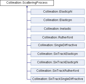
ScatteringProcess is an abstract base class for individual point-like scattering processes. It contains a pointer to the Material and CrossSections classes, the process cross section, the beam energy, and two functions: Configure() and Scatter().
MERLIN contains a number of ScatteringProcesses, including the SixTrack-like variants (based on K2 scattering); those currently available are shown in Fig. 11.
The user can select from several predefined ScatteringModels. ScatteringModelMerlin provides the full scattering physics as described in [17]. ScatteringModelSixTrack provides a model based on the K2 scattering found in SixTrack. ScatteringModelSixTrackIoniz, ScatteringModelSixTrackElastic, ScatteringModelSixTrackSD provide hybrid models useful for testing the individual scattering processes independently. Table 4 shows combinations of processes in each model. It is also possible for the user to create a ScatteringModel and customise it by adding their required processes.
| Process | SixTrack | SixTrackElastic | SixTrackSD | SixTrackIoniz | Merlin |
|---|---|---|---|---|---|
| Rutherford | ST | ST | ST | ST | M |
| pn Elastic | ST | M | ST | ST | M |
| pN Elastic | ST | M | ST | ST | M |
| Single Diffractive | ST | ST | M | ST | M |
| Ionisation | ST | ST | ST | M | M |
The ScatteringModel class contains the functions required for performing collimation. A predefined or user-created combination of ScatteringProcesses may be used, and are handled by the ScatteringModel in order to compute cross sections, path lengths, and perform bulk (ionisation and MCS) and point-like scattering. The ScatteringProcess must be attached to the CollimateProtonProcess.
The path length is the average distance a proton travels through a material before colliding with a material nucleus, it is calculated in the PathLength() function for each proton at each iteration of scattering, using the mean free path.
As a proton travels through a material it collides with electrons, these collisions may result in the removal of electrons, and a loss in proton energy. The interaction is defined by the Bethe-Bloch equation [18]. MERLIN offers an overloaded EnergyLoss() function to calculate the energy loss that takes place due to ionisation in a material. The basic function performs energy loss according to the Bethe-Bloch equation [18]. The overloaded function is a more complete treatment of the energy loss due to ionisation using higher-order corrections (considered in [9]). In summary, MERLIN only adds the effects that are relevant to LHC energies: the effect due to the dielectric polarisability of solid materials, the Mott correction which is an enhancement from close collisions due to spin, and the finite size correction taking into account the size and structure of the proton. As well as these corrections, the energy spread of the outgoing proton is sampled using the Landau distribution, which is a more accurate representation of the physical effect [18].
A proton travelling through a material will perform many small-angle elastic scatters from the electrons and nuclei, known as multiple Coulomb scattering (MCS), this is performed in the Straggle function.
ParticleScatter() is called when a particle has travelled its path length and remains in the material, which means it will interact with a material nucleus or nucleon (i.e. a point-like scatter).
2.8 Outputs
The main output from a collimation simulation is the loss map. This is a count of particle losses binned either by element or by position around the ring. MERLIN records these using the CollimationOutput class. Typically, losses from collimators and other elements are recorded together. No significant post processing is needed, as all the aperture checking happens on-line. Figure 12 shows a loss map for the LHC ring at the 6.5 TeV squeezed configuration. The losses in the betatron collimation region in IR7 are clearly visible, as are losses in the TCTs around the experiments.


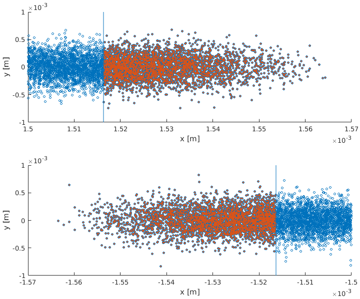
MERLIN also provides outputs that are useful for diagnostics and better understanding of the collimation process. The ScatteringModel::JawImpact() function outputs the coordinates of particles that impact the front face of selected collimators. As well as coordinates, the turn at which the impact occurred is also output, allowing the user to observe any change in the impact parameter over time. This output is useful for observing the effect of the HEL. An example of this output for a single turn in a collimation simulation is shown in Fig. 13, showing the correspondence between the initial distribution (which starts immediately in front of the primary collimator), with the recorded impact coordinates.
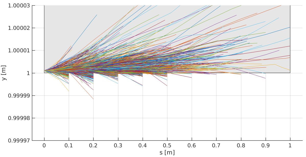
The ScatteringModel::ScatterPlot() function stores the position of particles at each path length step in order to plot scattering tracks along the collimator. This function has been a useful tool for debugging the collimation process, ensuring that aperture checks are performed at appropriate intervals, and showing the effect of the collimation bin size. In Fig. 14 the effect of the collimation bin size is illustrated. Particles undergo scattering, MCS, and ionisation energy loss for as long as they are in the collimator jaw. Even if a particle has exited a collimator jaw, the aperture check cannot take place until the particle has travelled a path length , or at the end of the collimation bin. This is evident as particle tracks abruptly stop at 10 cm intervals in the figure. By reducing the bin size, a small path length is forced, and computation time will increase, however by using a larger bin size protons may undergo significantly more bulk scattering (MCS and ionisation energy loss) when they have in fact already left the collimator jaw. The 10 cm bin size that is used by default allows regular aperture checks without enforcing too small a path length, or compromising the condition of protons that return to the bunch after undergoing scattering in a collimator jaw.
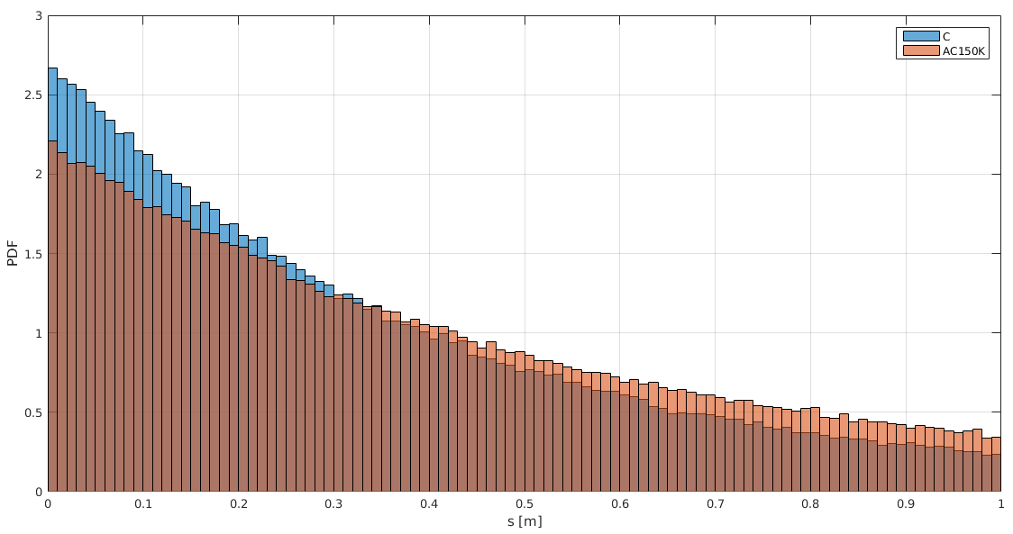
ScatteringModel::JawInelastic() stores the coordinates of inelastic interactions. This provides a necessary comparison tool to observe the effect of different collimator materials; an example histogram of the distribution of losses in a given collimator is shown in Fig. 15.
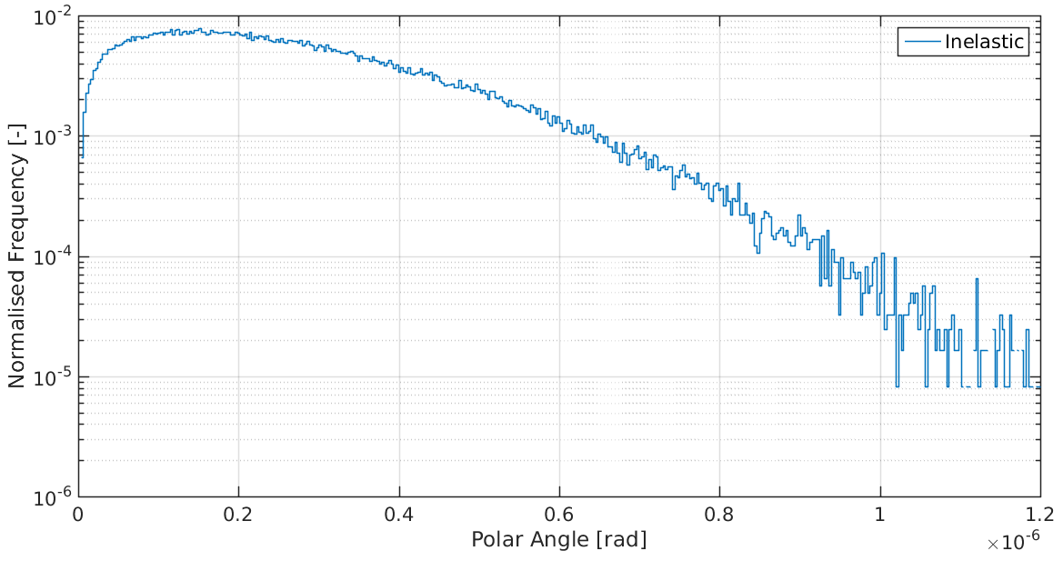
ScatteringModel::SelecScatter() stores the coordinates of selected interactions, outputting the momentum transfer and the polar angle as well as other quantities. As the raw data files produced can be very large, the OutputSelectScatterHistogram() function was created to histogram the data and produce a smaller output. An example of the histogrammed polar angle data is shown in Fig. 16.
3 Development
MERLIN consists of 39k lines of C++ code (LOC), along with 4.8k LOC of examples and 1.8 LOC of tests. CMake is used as the build system, allowing it to be compiled on a range of platforms. The source code is held in Git revision control repository [13].
MERLIN has a growing automated test suite. This is run daily on several physical and virtual machines with a range of operating systems, compilers and CPU architectures. The results uploaded to the CERN CDash server [19]. This allows rapid identification of issues in new development. The test suite performs dynamic analysis using the Vagrind toolset [20] to identify memory leaks and other related errors.
The Git distributed revision system offers a systematic method for making and recording changes to the source code. New features and fixes can be developed on a branch, and then merged into the master branch when tested and ready. This keeps the master branch in a usable condition and makes it easy to back out a change if it is found to have a negative effect. The master branch is hosted on the GitHub service, which also provides issue tracking and management of branches and merges.
4 Acknowledgements
This work is supported by STFC (UK) grant High Luminosity LHC : UK (HL-LHC-UK), grant number ST/N001621/1.
References
- [1] International Linear Collider, Linear Collider Collaboration, https://www.linearcollider.org/ILC, last accessed April 24th 2018.
- [2] F. Poirier et al., An ILC Main Linac Simulation Package Based on MERLIN, Proc. 10th European Particle Accelerator Conference, 2006.
- [3] D. Kruecker et al., MERLIN-Based Start-To-End Simulations of Luminosity Stability for the LHC, Proc. 22nd Particle Accelerator Conference, 2007.
- [4] D. Kruecker et al., Simulation Studies on Coupler Wakefield and RF Kicks for the International Linear Collider with MERLIN, Proc. 11th European Particle Accelerator Conference, 2008.
- [5] CERN BE-ABP, SixTrack: Single Particle Tracking Code, http://frs.home.cern.ch/frs/, last accessed April 24th 2018.
- [6] T. Trenkler and J. B. Jeanneret, K2, a software package evaluating collimation systems in circular colliders (manual), CERNSL/94105 (AP), 1994.
- [7] G. Robert-Demolaize et al., A New Version of SixTrack with Collimation and Aperture Interface, Proc. 21st Particle Accelerator Conference, 2005.
- [8] The FLUKA Code: Developments and Challenges for High Energy and Medical Applications, T.T. Bohlen, F. Cerutti, M.P.W. Chin, A. Fasso‘, A. Ferrari, P.G. Ortega, A. Mairani, P.R. Sala, G. Smirnov, and V. Vlachoudis, Nuclear Data Sheets 120, 211-214, 2014.
- [9] James Molson, Proton scattering and collimation for the LHC and LHC luminosity upgrade, PhD Thesis, University of Manchester, 2014.
- [10] Haroon Rafique, MERLIN for High Luminosity Large Hadron Collider Collimation, PhD Thesis, University of Huddersfield, 2016.
- [11] A. Valloni, H. Rafique, A. Mereghetti, J.G. Molson, R. Appleby, R. Bruce,E. Quaranta, S. Redaelli, MERLIN Cleaning Studies with Advanced Collimator Materials for HL-LHC, Proc. 7th International Particle Accelerator Conference, 2016.
- [12] A. Valloni, H. Rafique, R. B. Appleby, R. Bruce, J. G. Molson, A. Mereghetti, S. Redaelli, S. C. Tygier, MERLIN Simulations of the LHC Collimation System with 6.5 TeV Beams, Proc. 7th International Particle Accelerator Conference, 2016
- [13] MERLIN on GitHub, MERLIN Collaboration, https://github.com/MERLIN-Collaboration/MERLIN, last accessed April 24th 2018.
- [14] A. Valloni, H. Rafique, R. B. Appleby, R. J. Barlow, J. G. Molson, S. Tygier, MERLIN Composite Materials, These proceedings, 2017.
- [15] H. Rafique, R. B. Appleby, R. J. Barlow, J. G. Molson, S. Tygier, A. Valloni, HL-LHC Hollow Electron Lens Integration using MERLIN, These proceedings, 2017.
- [16] MAD - Methodical Accelerator Design, CERN, http://mad.web.cern.ch, last accessed April 24th 2018.
- [17] R. B. Appleby, R. J. Barlow, J. G. Molson, M. Serluca, A. Toader, The practical Pomeron for high energy proton collimation, Eur. Phys. J. C (2016) 76:520, http://doi.org/10.1140/epjc/s10052-016-4363-7
- [18] Passage of particles through matter, Particle Data Group, http://durpdg.dur.ac.uk/lbl/index.htmll, 2005.
- [19] CERN ABP CDash server, http://abp-cdash.web.cern.ch/abp-cdash/, last accessed April 24th 2018.
- [20] Valgrind, http://www.valgrind.org/, last accessed April 24th 2018.