INSIGHTS INTO THE MODELING OF SEISMIC WAVES FOR THE DETECTION OF UNDERGROUND CAVITIES
Abstract
Motivated by the need to detect an underground cavity within the procedure of an On-Site-Inspection (OSI), of the Comprehensive Nuclear Test Ban Treaty Organization, the aim of this paper is to present results on the comparison of our numerical simulations with an analytic solution. The accurate numerical modeling can facilitate the development of proper analysis techniques to detect the remnants of an underground nuclear test. The larger goal is to help set a rigorous scientific base of OSI and to contribute to bringing the Treaty into force. For our 3D numerical simulations, we use the discontinuous Galerkin Spectral Element Code SPEED jointly developed at MOX (The Laboratory for Modeling and Scientific Computing, Department of Mathematics) and at DICA (Department of Civil and Environmental Engineering) of the Politecnico di Milano.
1 Introduction
If a suspicious seismic signal has been recorded by the International Monitoring System of the Comprehensive Nuclear-Test Ban Treaty Organization (CTBTO), the responsibility of the On Site Inspection (OSI) division is the investigation of the source area to collect evidence that reveals whether a nuclear test has been conducted and, if the circumstances permit, to get a final localization of ground zero. At the location of an underground nuclear explosion, a damaged zone is expected to be present, including a cavity. Thus, cavity detection might become a major tool for the OSI division.
In order to contribute to the method design, we investigate the scattering of the seismic wave field in the presence of an acoustic inclusion. The underlying technical questions of the OSI are still quite new and there are only few experimental examples that have been suitably documented to build a proper scientific groundwork. This motivates the investigation of the wave field on a purely numerical level and the simulation of potential observations based on recent advances in numerical modeling of wave propagation problems.
As much as this is a challenging task in the applied fields, it is also interesting from a modeling and computational point of view. The classical scattering problem considers the wave propagation in an acoustic medium with an elastic obstacle, whereas we focus on the inverse situation of an elastic medium with an acoustic inclusion.
For very simple cases the propagation of seismic waves can be described analytically [28, 1, 2, 10]. For more complex cases, seismic waves with a significantly smaller or larger wave length than the characteristic size of the obstacle can be approximated by ray tracing methods [13] or effective medium methods [24, 44, 37], respectively. However, we are interested in the scattered wave patterns when the wavelengths of the propagating waves and the characteristic size of heterogeneities are comparable and here numerical methods become essential. There are many textbooks discussing the numerical modeling of seismic wave propagation [25, 11, 15, 33, 23, 9, 42]. Here, SPEED [31, 7, 6, 20] is applied to a three-dimensional (3D) elastic-acoustic scattering problem for comparison. We consider in particular a 3D scattering problem consisting of a low-velocity spherical acoustic inclusion embedded in a high-velocity elastic medium, whereby a plane P-wave is scattered by the inclusion having a diameter similar to the P-wave’s wavelength. For this case Korneev and Johnson [27] provide an analytic solution which is used as the reference solution for the comparison of the numerical results. A similar study in 2D has been discussed in [21]. Based on the analytic solution presented in [27] the investigation of seismic resonances origin to an acoustic inclusion was also discussed in [38].
2 Problem formulation
Let be an open bounded set , having a spherical obstacle/acoustic inclusion located at the origin as illustrated in Figure 1. We consider the elastic wave propagation problem in described by
| (1) |
where is the mass density within the subdomain , , and is the corresponding displacement unknown vector. The Cauchy stress tensor is expressed with the domain-wise constant Lamé parameters and by

We recall that the Lamé parameters are related to the pressure () and shear () velocity of the media as follows
| (2) |
Moreover, we also define the subdomain-wise constant wave number by
| (3) |
Since we are interested in the scattered wave field subject to an incoming pressure plane wave, we consider a distribution of body force given by
| (4) |
with time profile acting on the plane for some far from the acoustic inclusion at the bottom of the domain.
2.1 Coupling conditions
At the interface between and we request only continuity in the normal component of the displacement as well as of the stress tensor:
| (5) | ||||
| (6) |
where is the normal vector pointing outward from . Note that equation (5) is equivalent to impose a null jump for the normal component of the displacement field across the interface between the elastic and acoustic domain, that is on . However, if the difference of displacement in tangential direction stays small, this condition can be replaced by the jump condition , which will be used in the DG formulation proposed in Section 3.2. Note also that equation (6) includes a free surface condition in the tangential components for elastic medium.
2.2 Boundary conditions
A possible approach to approximate the radiation condition for the unbounded domain consists in modeling an absorbing boundary layer by the introduction of a fictitious traction on . Here, we consider the local P3 paraxial conditions presented in [39], which is sufficiently accurate if , as in the application under consideration. More specifically, the P3 paraxial absorbing conditions read as
where and are two mutually orthogonal unit normal vectors on the plane orthogonal to normal vector pointing outward of . and span the tangent plane to the surface in each point such that is a right handed Cartesian system. The traction term defined on the absorbing boundary in the local coordinate system has then the following expression
that can be easily rewritten in term of the gobal coordinate system . See [12] for more details.
3 Numerical discretization
Piece-wise constant material parameters result in contrasting wave lengths and give reason to approximate the solution with distinct discretization parameters in each domain , . Especially when the velocity contrast is comparably high, this motivates to use proper space discretization parameters in each subdomain, in order to catch the main features of the wave phenomenon. This motivates the choice of the following Discontinuous Galerkin numerical discretization.
3.1 Mesh and trace operators
We consider a (not necessarily conforming) decomposition of into two nonoverlapping polyhedral sub-domains and , i.e., , . On each , we consider a conforming, quasi-uniform computational mesh of granularity made by open disjoint elements , and suppose that each is the image through a bilinear map of the reference hexahedron . We define an interior face as the non-empty interior of , for some and , and collect all the interior faces in the set . Moreover, we define as the sets of all boundary faces where absorbing boundary conditions are imposed. Finally, we assume that for any element and for any face it holds . For more details see [22, 34] as well as [17, 18] for the case of highly discontinuous coefficients.
Let and be two elements sharing a face , and let be the unit normal vectors to pointing outward to , respectively. For (regular enough) vector and tensor-valued functions and , we denote by and the traces of and on , taken within the interior of , respectively, and set
where . On , we set , , , .
3.2 Discontinuous Galerkin Sprectral Element discretization
For each subdomain , we consider a nonnegative integer , and we define the finite dimensional space
where is the space of polynomials of degree in each coordinate direction on . Then, we define the finite dimensional trial space as . The semidiscrete Discontinuous Galerkin approximation of problem (1) reads: , find such that
| (7) |
subjected to the initial conditions . The right hand side is defined as
while the bilinear form as
| (8) |
for any , being and a positive parameter to be choosen large enough, cf. [6].
Remark.
Implicit in the derivation of formulation (7) is the use of coupling conditions described in section 2.1. For the sake of presentation we derive formulation (7) in the case of a partition made by two subdomain and . However, it can be easily extended for accommodating different elastic or acoustic subdomains, as it will be considered in Section 5. Finally, note that the discrete solution is piecewise discontinuous across macro elements and (weak) continuity is enforced based on employing, at a subdomain level, the symmetric interior penalty DG (SIPG) method [6]. We refer to [3] for a unified analysis of the -version of the method and to [4, 5] for the version of the method and it analysis.
3.3 Fully discrete formulation
In this section we present the time integration of the semi-discrete formulation (7). By fixing a basis for the discrete space , the semi-discrete algebraic formulation of problem (7), reads as
| (9) |
supplemented by the initial conditions . Here, denoting by the total number of degrees of freedom, the vector contains, for any time , the expansion coefficients of the semi-discret solution in the chosen set of basis functions. Analogoulsy, and are the matrices representations of the bilinear forms
respectively, cf. (7). Inserting the absorbing conditions from Section 2.2 for the boundary term give rise to the matrices and in equation (9). Finally is the vector representation of the linear functional containing the body force term , cf. (7).
For the time integration of the system of second order ordinary differential equations (9), we employ the leap-frog method [36], that is a widely employed time marching scheme for the numerical simulation of elastic waves propagation, see for example [8, 14, 26, 32]. With this aim we subdivide the time interval into subintervals of amplitude , and we denote by and the approximation of and at time , , respectively. System (9) approximated with the leap-frog scheme reads as:
| (10) | ||||
| (11) |
for , with . We notice that (11) involves a linear system with matrix to be solved at each time step. The choice of the basis functions spanning the space strongly influences the structure of the matrix and, therefore, the computational cost related to the solution of the linear system. Furthermore, since the leap-frog method is an explicit second order accurate scheme, to ensure its numerical stability a Courant - Friedrich - Levy (CFL) condition has to be satisfied (see [36]).
4 Analytic solution
For the following analysis, we consider the total wave field expressed as the sum of the incident () and the scattered () wave fields as follow
| (12) |
In a homogeneous elastic domain the incident wave origin to a body load (4) has only a contribution in the 3rd component which is given by
| (13) |
Note that solves then the elastic wave question in with parameters from . Hence, to recover the total wave field it is sufficient to solve the following problem for :
| (14) |
together with solely absorbing conditions at the boundary , cf. Figure 1. This approach has also been used in [19].
In case of a time-harmonic force load outside the domain (at infinity), the body force equals zero, i.e. . For this case, an analytic solution is presented by Korneev and Johnson[27] and summarized here for the sake of completeness. In the time-harmonic case, the incident as well as the scattered wave fields can be expressed as
| (15) |
where and are complex-valued functions. In particular, the interaction of the incident wave with the sphere gives rise to a scattered displacement field inside as well as outside of the sphere. To this end we omit the time dependence and use the following notation
| (16) |
In order to construct an analytical solution [27] used the system of spherical vectors in the spherical coordinte system with unit vectors developed by Petrashen [35]
where is distance from the center of the sphere with and are the unnormalized spherical harmonic functions, defined as
such that an arbitrary vector function can be represented in the form
In this coordinate system an incident plane harmonic P-wave, propagating in the positive z-direction in is given by
where the are the spherical Bessel functions. Furthermore it is possible to express the scattered wave field inside and outside the sphere separately by
respectively, where are the spherical Hankel functions of second kind and are the coefficients which are given explicitly in [27]. The wavenumbers and are given by and , where and are the propagation velocities of P- and S-waves inside () and outside () of the cavity, respectively. The unknown coefficients can be determined by solving a linear system that arises from the following continuity conditions, which are valid at the acoustic-elastic interface:
The first condition describes the continuity of the normal component of the displacement. The tangential displacement components are free due to the fact that no shear stress can be transmitted to the acoustic domain. Since in the traction vector points in the normal direction with respect to the interface. Thus the second condition forces the tangential components of the traction vector to be zero, for any vector which is orthogonal to . Thus, the acoustic-elastic interface acts as a free surface for the components tangential to the interface and transmits only normal components of displacement and stress between the acoustic and elastic domains.
The total wave-field outside and inside the cavity is given by
In order to retrieve the solution of the wave equation for a time dependent incident field, the scattering problem is solved for many frequencies and the time harmonic functions (Eq. 15) are combined by applying inverse Fourier transform. In order to compare the analytical with numerical solutions all wave fields are convolved with the Ricker wavelet
describing a common seismic model wavelet. However, any other wavelet can be used instead in order to retrieve arbitrary time histories. With the convolution theorem the calculated synthetic seismogram can be expressed as
where and are Fourier’s transform and it’s discrete inverse, respectively. is the set of frequencies for which the solution is computated.
5 Results
In this section we want to address a 3D scattering wave propagation problem consisting of a low-velocity spherical acoustic inclusion embedded in a high-velocity elastic medium. In particular we want to compare our numerical results with respect to the analytical one provided by Korneev and Johnson in [27].
5.1 Mesh generation
Special attention must be given to the grid generation as meshing a spherical inclusion inside a cube with hexahedrons is not a trivial task. Especially as in this case, when the wave length inside the sphere is much smaller than outside. This gives reason to chose a smaller mesh size inside the inclusion. Using non-curved elements non-conforming meshes inside and outside the sphere will lead to empty and overlapping regions which would lead to numerical instabilities and must therefore be avoided. As a work-around we added another small box around the sphere such that the non-conforming interface can be generated between the small and the big cube while having a conforming interface between the small cube and the sphere, see Figure 2. A strategy to overcome this issue is presented in [43]. However, the parameters are discontinuous across the boundary of the sphere and therefore we can select different discretization parameters inside and outside the spherical cavity. In summary, DG jumps are applied to both interfaces: the non-conforming interface between the two elastic cubes and the conforming interface between the acoustic and elastic domain where physical parameters are discontinuous.

5.2 Input data
The mechanical parameters for the elastic and acoustic materials are given in Table 1.
| Domain | [kg/m3] | [m/s] | [m/s] |
|---|---|---|---|
| 1000 | 0 | 1500 | |
| 2700 | 2310 | 4000 |
The time profile of our seismic source is described by the Ricker wavelet
where is the angular peak frequency of the Ricker wave and a time offset. The shape of the Ricker profile is shown in Figure 3 and more details on the frequency band can be found in [40].

Furthermore we were interested in the case of an incident Ricker wave pulse of a mean wave length of the size of the cavity, i.e. . Hence we chose:
However, to minimize numerical dispersion errors we had to choose the grid size according to S-velocity and the maximum frequency in the Ricker spectrum as follows
in order to obtain the resolution of 10 points per wavelength (reasonable for small wave numbers) and avoid spurious numerical effect from the artificial boundary. With the same argumentation one should choose the grid size in the acoustic domain by
Note that we use different grid sizes in the domain resulting in a non-conforming mesh, but we use the same polynomial degree. In our domain of interest this would lead to more than grid points and more than spectral nodes. The minimal grid size in this mesh is about resulting in a time step size
For a simulation time until this gives 125000 time steps.
However, due to limited computational resources we rather resolve for the peak frequency and put the boundary further away, i.e.
on a domain of dimension reducing the number of grid points to about 56000. With a minimal grid size the corresponding time step size is and 25000 time steps.
5.3 Analysis of the results
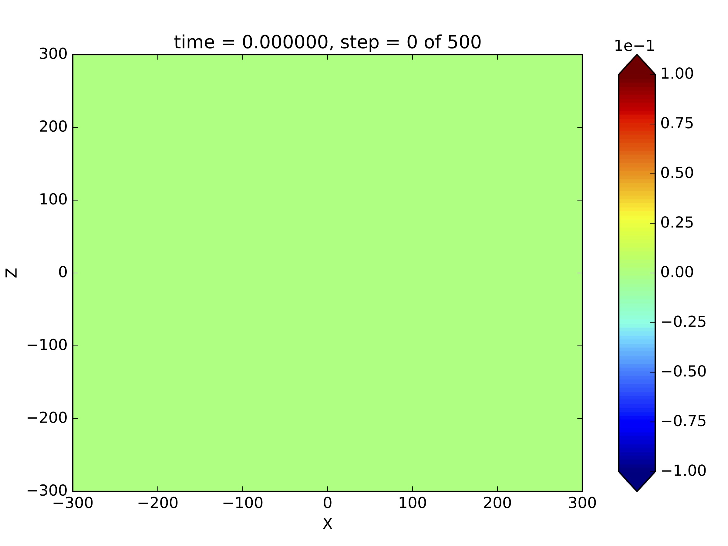
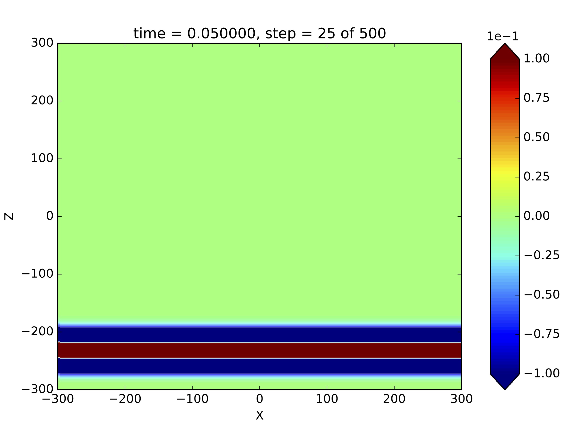
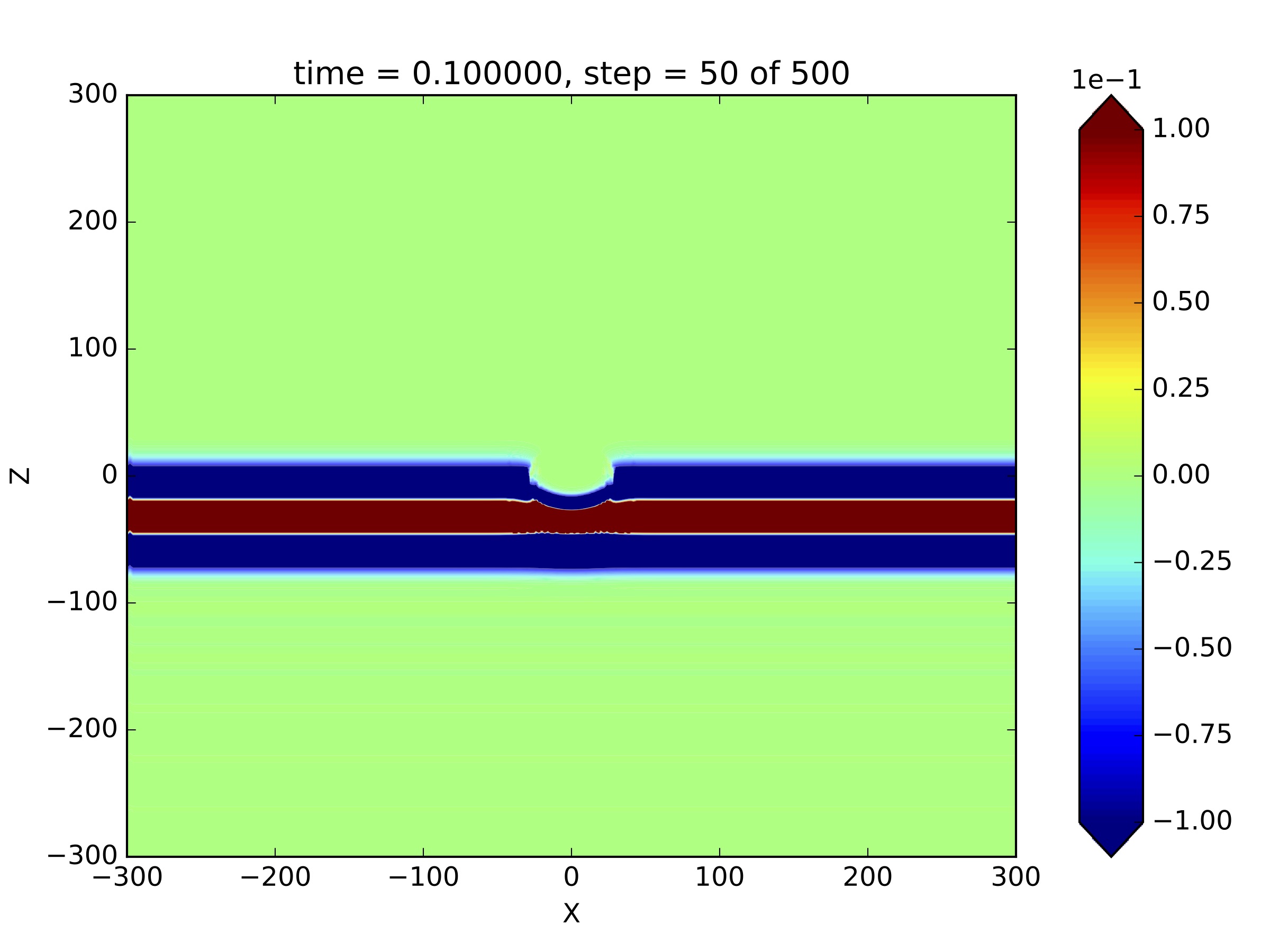
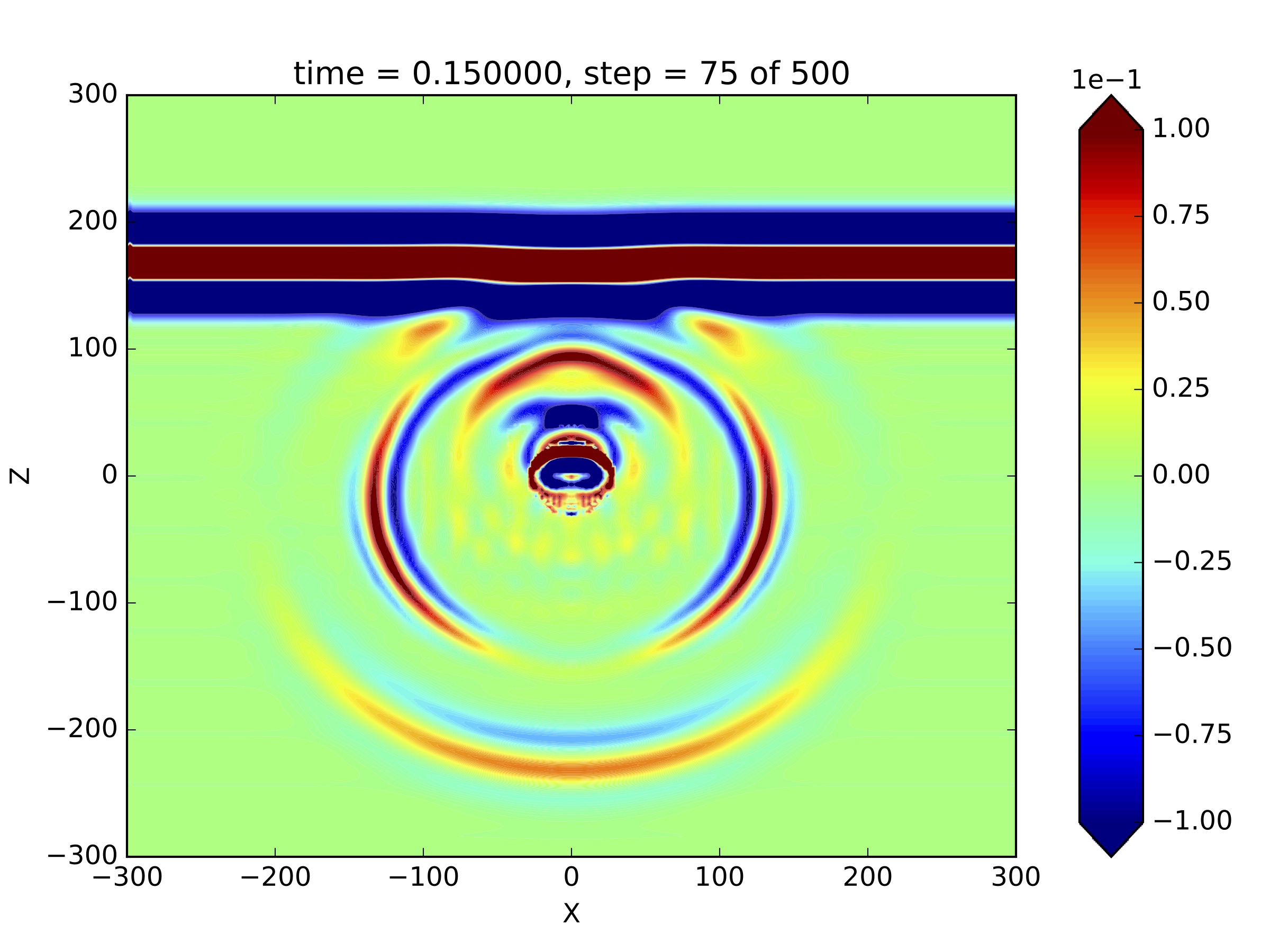
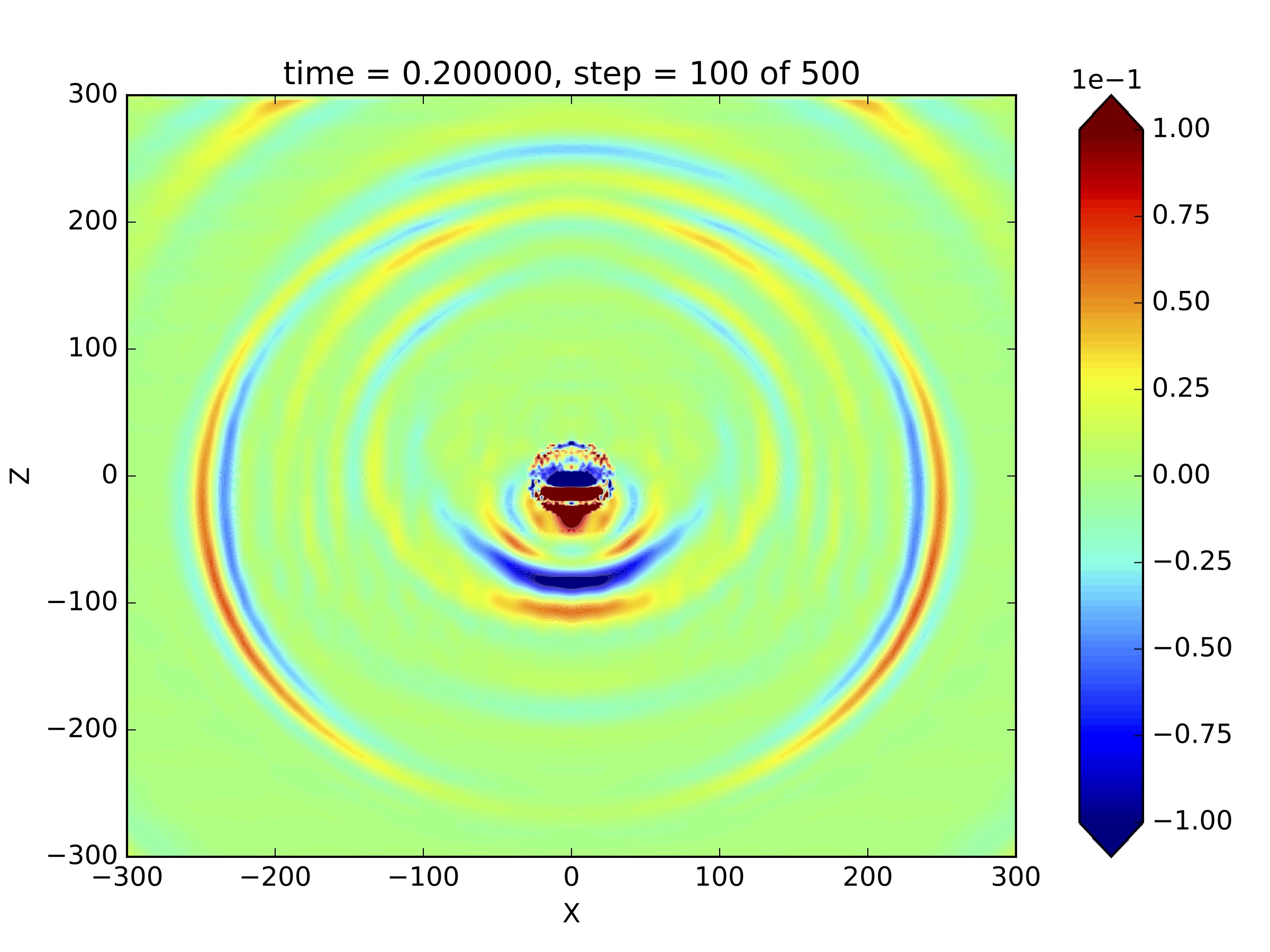
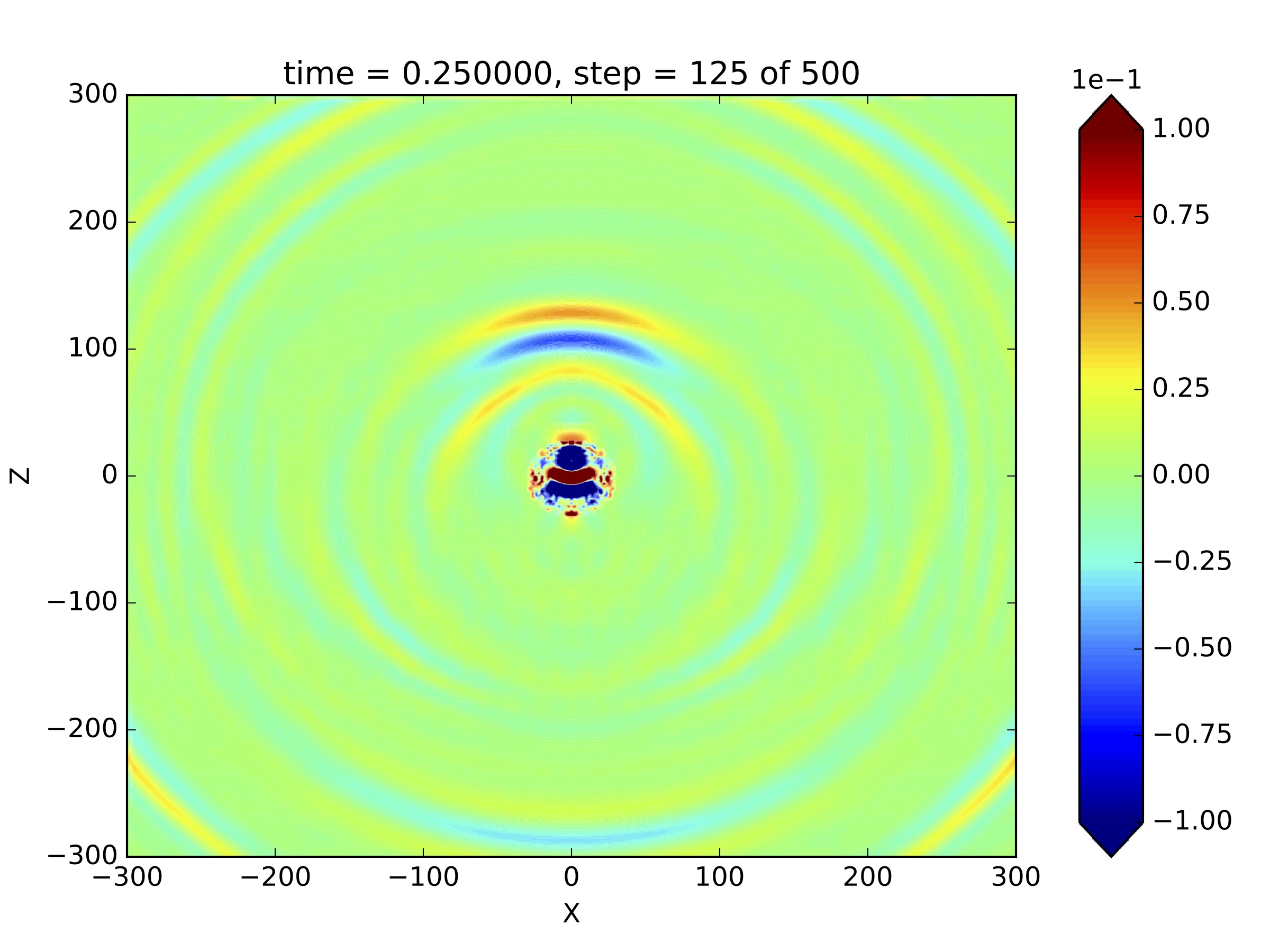
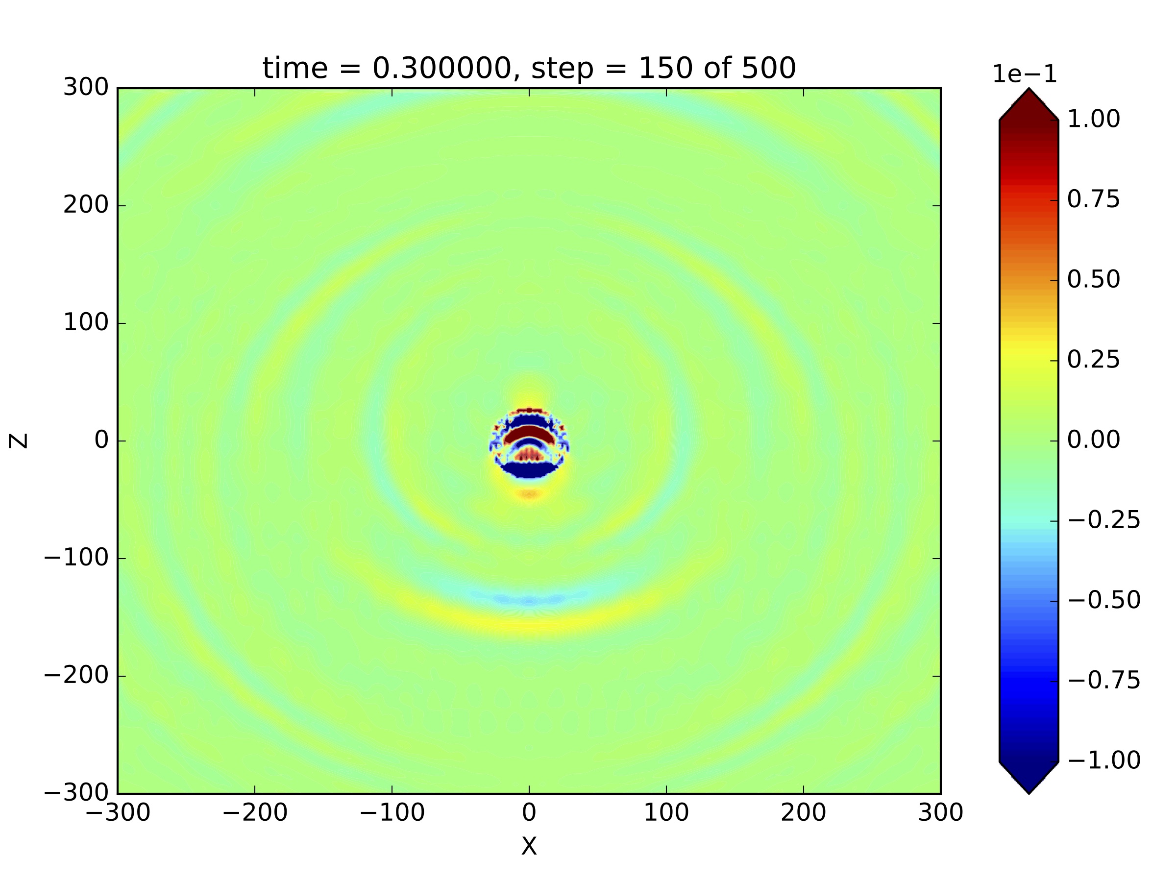
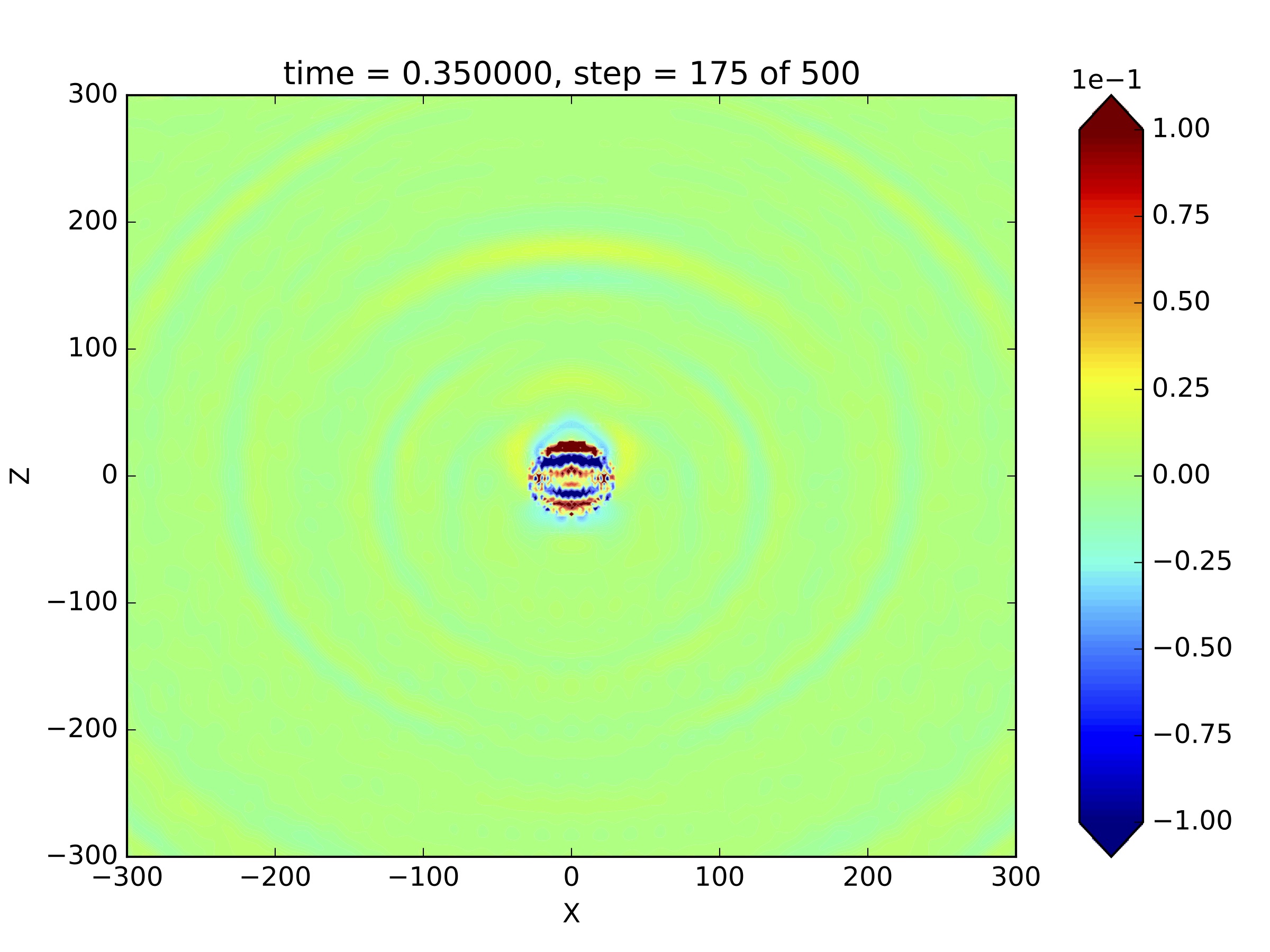
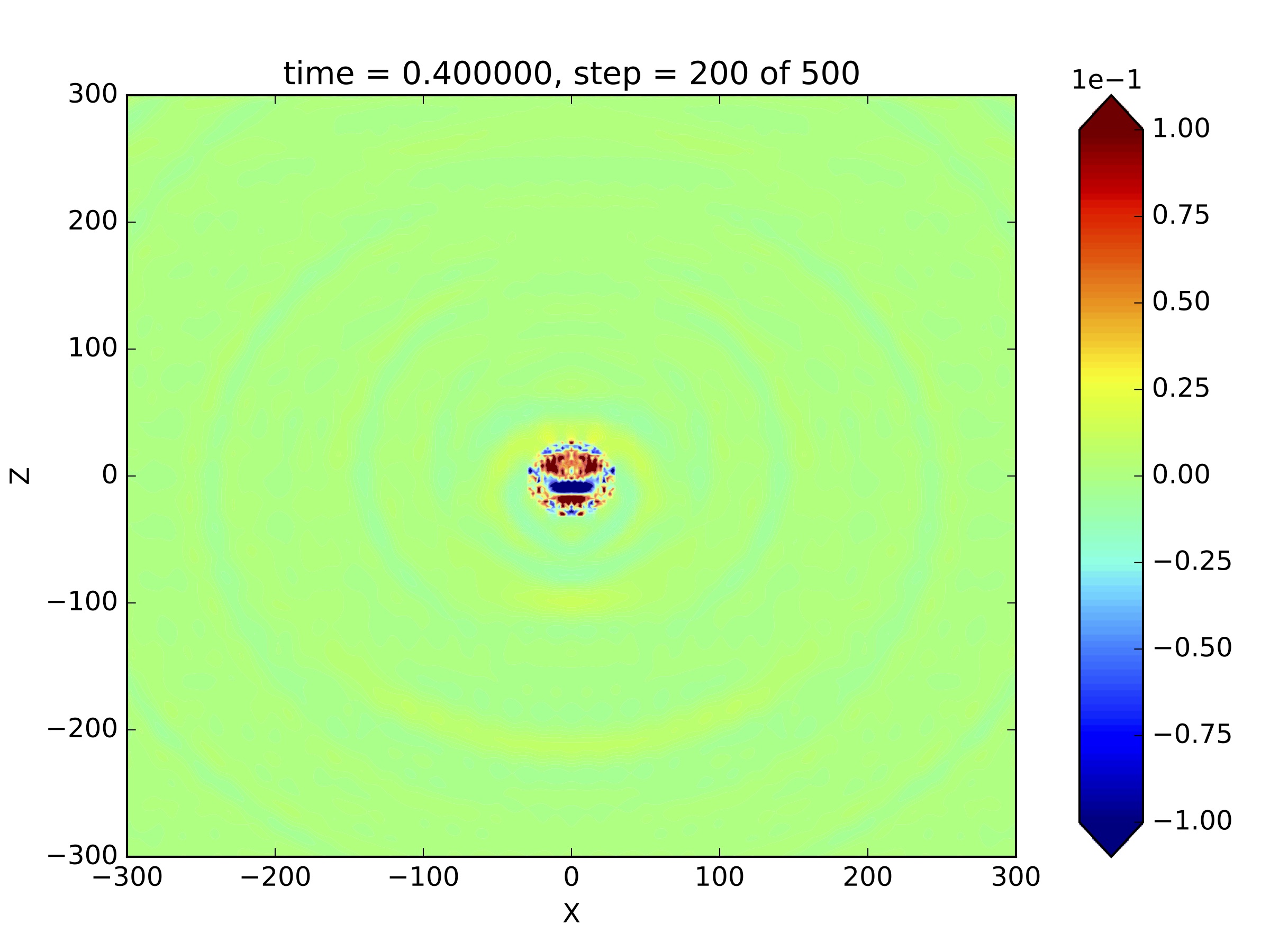
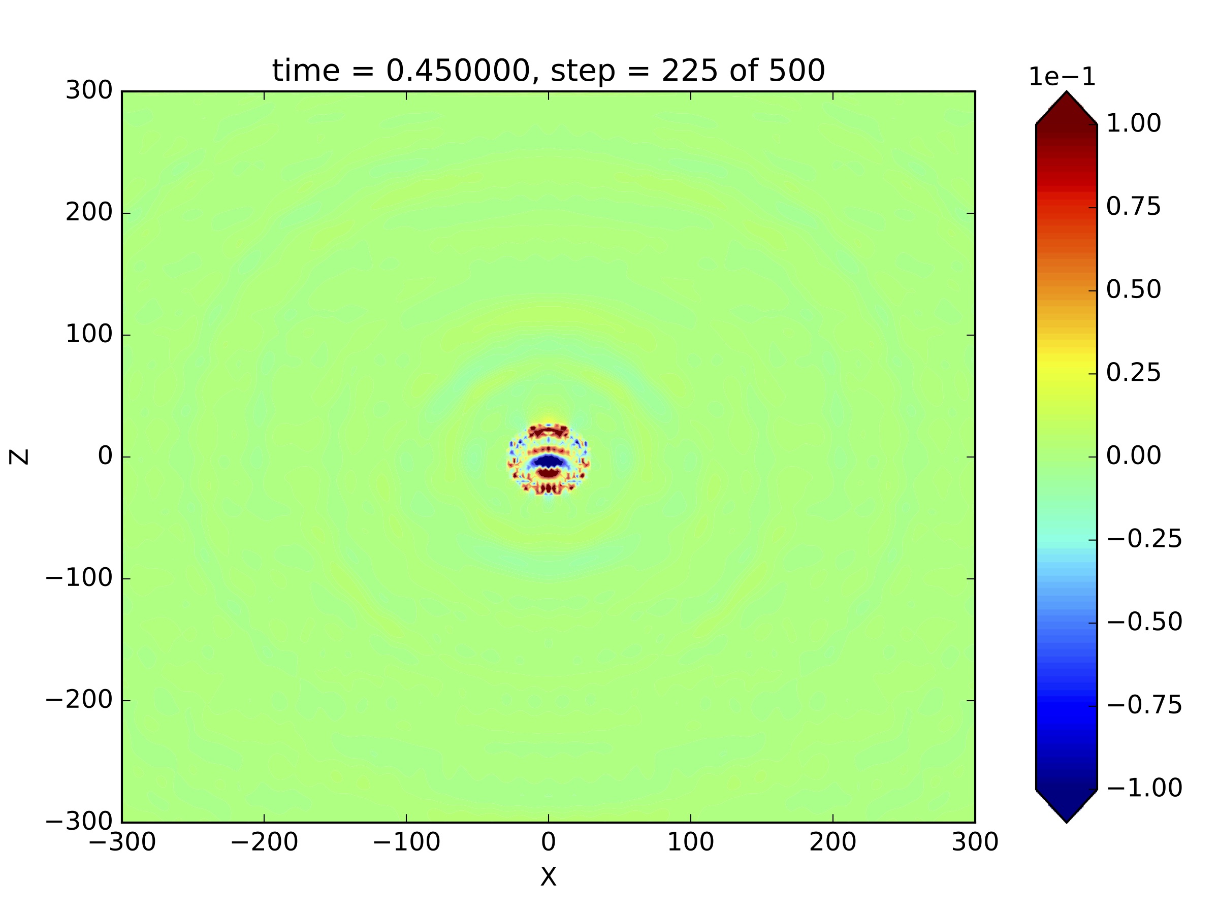
In order to provide an overview we show in Figure 5 snapshots of the wave field in the XZ-plane. The incident plane P-wave travels with constant amplitude through the elastic domain from the bottom to the top with a velocity of and reaches the acoustic-elastic interface at about . With a positive impedance contrast from the elastic to the acoustic domain given by the material parameters in Table 1 about 75% of the incident wave is reflected resulting in the primary scattered spherical P- and S- waves which can be seen at s. About 25% are transmitted into the cavity where it propagates only as P-wave with a lower velocity of . Each time the acoustic wave hits the boundary of the cavity, about 75% of its energy are now reflected back and only about 25% are transmitted to the elastic domain. This yields an acoustic wave energy trapped inside the cavity expressed in multiple reverberations that couple out into the elastic medium periodically which can be seen for to . In [38] this resonance phenomenon has been investigated in more detail based on an analytic solution.
For validation we compare the analytic and the numerical solution along four profiles which are illustrated in Figure 4. Profile A is a vertical profile for and the coordinate ranging from to with a distance of while profile B is a horizontal profile for and the coordinate ranging from to . The horizontal profiles C and D are located further away with vertical locations at and from the cavity, which is located at the origin. Profile C and D range horizontally from to with a distance of .

Profile A in Figure 6 shows the comparison of the displacement time histories in the Z-component (seismograms) for locations crossing the cavity in vertical direction. Seismograms with a gray background show monitoring points inside the acoustic cavity. The incident plane P-wave reaches the acoustic-elastic interface at about . Along this profile only the primary back scattered spherical P- wave (decreasing in amplitude with distance and time) is visible. A scattered S-wave is not formed since at the plane P-wave hits the spherical interface with an incidence angle equal to zero. Further, one can see the wave continue to propagate inside the cavity (gray zone) with a lower velocity. Due to the velocity contrast the wave is trapped inside the cavity emitting about 25% of its energy into the elastic medium each time the wave hits the boundary of the cavity resulting in multiple reverberations decreasing in amplitude with distance and time. The wave inside the cavity gets also more and more diffracted with time due to the spherical geometry of the cavity. Further, one can see that the incident wave field is shielded by the cavity creating a shadow zone which causes the suppression of the incident wave field up to about above the cavity. Due to wave-front healing the incident wave field is present above the cavity and seems to be unperturbed for .
The profile A crosses the cavity at the top and bottom, where the direction normal to the interface points into the direction. Thus the component at in Figure 6 is the normal component with respect to the interface. The acoustic-elastic interface condition requires the continuity of the normal component at the interface which can be seen in Figure 6. The overall waveform fit is quite satisfying. The direct and multiple scattered phases are reliably captured. However some misfit due to numerical dispersion occurs, getting more pronounced with time. As discussed in section 5.2, this could be overcome by using a finer grid using, but with a huge computing time.
Figure 7 shows the profile crossing the cavity in horizontal direction. Here the seismograms for and are computed in the acoustic and elastic domains, respectively. The incident wave field passes the profile a little later than . In the elastic domain the incident field is followed by the primary scattered S-wave. The transmitted P-wave inside the cavity shows the strongest amplitudes at the center of the cavity. As described above multiple reverberations occur with decaying amplitudes, cf. Figure 5.
Profile B is oriented horizontally, hence the components show the tangential component at the interface. The physical interface condition only demands the continuity of the displacement in normal direction. As discussed in Section 2.1, the DG-implementation forces all three components to be continuous at the interface. However, we can see in Figure 7 that the discontinuity of the tangential component is well fitted for the primary transmitted wave. The scattered numerical waves in the elastic domain coincide very well with the analytic solution. The multiple internal reverberations are well captured except for numerical dispersion. A misfit inside the cavity is present near the interface, which do not seem to affect the seismograms in the elastic domain.
Figure 8 shows seismograms for profiles C and D in the back- and forward-scattered regimes, respectively. The profiles are located in distance above and below the cavity in the elastic medium. In the back-scattered regime in Figure 8 (top) the incident plane wave is separated from the scattered waves and arrives earlier in time at about . The primary scattered P-wave is a distinct wave arrival at about . Two further scattered P-wave arrivals from internal reverberations inside the cavity are well pronounced. The first also coincides with the arrival of the secondary S-wave. Further, from the cavity decoupled S-waves occur from internal acoustic reverberations that are from P-to-S converted during the transmission. On the component the spherical-like scattered P-waves show strong amplitudes near , while S-waves are more pronounced for large . At S-waves fade out for two reasons, first no P-to-S conversion takes place for an incidence angle equal to zero, neither during reflection nor during transmission of later acoustic reverberations, and second due to the projection of the shear particle motion on the direction. In the forward-scattered regime in Figure 8 (bottom) the primary scattered waves directly follow the incident wave. Internal reverberations cause the later arrivals as discussed above.
All physical features are captured by the numerical solution. The waveform fit is very satisfying. Small deviations due to numerical dispersion can easily be overcome by a finer grid or higher polynomial degrees.


6 Conclusion/Discussion
The numerical computation of the elastic scattering wave field with SPEED stands in good agreement with the analytic solution for a spherical shaped inclusion. The validation for this study paves the way for a comprehensive understanding of the physical characteristic based on numerical computations. However, several aspects are open for improvement. While numerical deviations can be observed in the acoustic domains, all physical features in the elastic domain are well resolved. In the elastic domain no signal information is lost nor any artificial signals are present. The acoustic-elastic coupling is an open research topic for implementation in SPEED [30] and is currently under investigation. Other combinations of spatial and temporal discretization methods could use local [29] or Lax-Wendroff time-stepping [16]. An alternative for absorbing boundary conditions was discussed in [41].
Acknowledgments
We acknowledge financial support by the Vienna Science and Technology Fund (WWTF) project MA14-006. The computational results presented have been achieved in part using the Vienna Scientific Cluster (VSC). Ilario Mazzieri has been partially supported by the research grant Scientific Independence of young Researchers (SIR; RBSI14VT0S); ’PolyPDEs: Non-conforming polyhedral finite element methods for the approximation of partial differential equations’ by Italian Ministry of Education, Universities and Research (MIUR).
References
- [1] J. Achenbach, H. Lauwerier, and W. Koiter. Wave Propagation in Elastic Solids: North-Holland Series in Applied Mathematics and Mechanics. North-Holland series in applied mathematics and mechanics. Elsevier Science, 1973.
- [2] K. Aki and P. G. Richards. Quantitative Seismology. Geology: Seismology. University Science Books, 1980.
- [3] P. F. Antonietti, B. Ayuso de Dios, I. Mazzieri, and A. Quarteroni. Stability analysis of discontinuous Galerkin approximations to the elastodynamics problem. Journal of Scientific Computing, 68:143–170, 2016.
- [4] P. F. Antonietti, A. Ferroni, I. Mazzieri, and A. Quarteroni. –version discontinuous Galerkin approximations of the elastodynamics equation. In Spectral and High Order Methods for Partial Differential Equations ICOSAHOM 2016. Lecture Notes in Computational Science and Engineering. M. Bittencourt et al. eds, 2017, doi: 10.1007/978-3-319-65870-4_1.
- [5] P. F. Antonietti, C. Marcati, I. Mazzieri, and A. Quarteroni. High order discontinuous Galerkin methods on simplicial elements for the elastodynamics equation. Numerical Algorithms, 71(1):181–206, 2016.
- [6] P. F. Antonietti, I. Mazzieri, A. Quarteroni, and F. Rapetti. Non-conforming high order approximations of the elastodynamics equation. Computer Methods in Applied Mechanics and Engineering, 209:212–238, 2012.
- [7] P. F. Antonietti, I. Mazzieri, A. Quarteroni, and F. Rapetti. High order space-time discretization for elastic wave propagation problems. In M. Azaïez, H. El Fekih, and J. S. Hesthaven, editors, Spectral and High Order Methods for Partial Differential Equations - ICOSAHOM 2012: Selected papers from the ICOSAHOM conference, June 25-29, 2012, Gammarth, Tunisia, pages 87–97, Cham, 2014. Springer International Publishing.
- [8] H. Bao, J. Bielak, O. Ghattas, L. F. Kallivokas, D. R. O’Hallaron, J. R. Shewchuk, and J. Xu. Large-scale simulation of elastic wave propagation in heterogeneous media on parallel computers. Computer methods in applied mechanics and engineering, 152(1):85–102, 1998.
- [9] K. Bathe. Finite Element Procedures. Prentice-Hall International Series in. Prentice Hall, 1996.
- [10] A. Ben-Menahem and S. Singh. Seismic Waves and Sources. Springer-Verlag, 1981.
- [11] J. Carcione. Wave Fields in Real Media: Wave Propagation in Anisotropic, Anelastic and Porous Media. Handbook of Geophysical Exploration: Seismic Exploration. Elsevier Science, 2001.
- [12] F. Casadei and E. Gabellini. Implementation of a 3D Coupled Spectral Element/Finite Element Solver for Wave Propagation and Soil-structure Interaction Simulations. Part I: Models. EUR 17730 EN, 1997.
- [13] V. Cerveny. Seismic Ray Theory. Cambridge University Press, 2001.
- [14] E. Chaljub, D. Komatitsch, J.-P. Vilotte, Y. Capdeville, B. Valette, and G. Festa. Spectral-element analysis in seismology. Advances in Geophysics, 48:365–419, 2007.
- [15] G. Cohen. Higher-Order Numerical Methods for Transient Wave Equations. Scientific Computation. Springer Berlin Heidelberg, 2001.
- [16] J. D. De Basabe and M. K. Sen. Stability of the high-order finite elements for acoustic or elastic wave propagation with high-order time stepping. Geophysical Journal International, 181(1):577–590, 2010.
- [17] M. Dryja. On Discontinuous Galerkin methods for elliptic problems with discontinuous coefficients. Comput. Methods in Appl. Math., 3(1):76–85, 2003.
- [18] M. Dryja, J. Galvis, and M. Sarkis. BDDC methods for discontinuous Galerkin discretization of elliptic problems. J. Complexity, 23(4-6):715–739, 2007.
- [19] S. Esterhazy, F. Schneider, I. Perugia, and G. Bokelmann. Application of high-order finite-element method to the P-wave propagation around and inside an underground cavity. Geophysics, 82(4):T197–T206, 2017.
- [20] E. Faccioli, F. Maggio, R. Paolucci, and A. Quarteroni. 2D and 3D elastic wave propagation by a pseudo-spectral domain decomposition method. Journal of Seismology, 1(3):237–251, Nov 1997.
- [21] M. Frehner, S. M. Schmalholz, E. H. Saenger, and H. Steeb. Comparison of finite difference and finite element methods for simulating two-dimensional scattering of elastic waves. Physics of the Earth and Planetary Interiors, 171(1):112 – 121, 2008. Recent Advances in Computational Geodynamics: Theory, Numerics and Applications.
- [22] E. H. Georgoulis, E. Hall, and P. Houston. Discontinuous Galerkin methods for advection-diffusion-reaction problems on anisotropically refined meshes. SIAM Journal on Scientific Computing, 30(1):246–271, 2007/08.
- [23] H. Igel. Computational Seismology: A Practical Introduction. Oxford University Press, 2017.
- [24] T. H. Jordan. An effective medium theory for three-dimensional elastic heterogeneities. Geophysical Journal International, 203(2):1343–1354, 2015.
- [25] K. Kelly, K. Marfurt, and S. of Exploration Geophysicists. Numerical Modeling of Seismic Wave Propagation. Number Bd. 13 in Geophysics reprint series. Society of Exploration Geophysicists, 1990.
- [26] D. Komatitsch and J. Tromp. Introduction to the spectral element method for three-dimensional seismic wave propagation. Geophysical Journal International, 139(3):806–822, 1999.
- [27] V. A. Korneev and L. R. Johnson. Scattering of elastic waves by a spherical inclusion - I. Theory and numerical results. Geophysical Journal International, 115(1):230–250, 1993.
- [28] A. Love. A Treatise on the Mathematical Theory of Elasticity. Cambridge University Press, 1927.
- [29] R. Madec, D. Komatitsch, and J. Diaz. Energy-conserving local time stepping based on high-order finite elements for seismic wave propagation across a fluid-solid interface. Computer Modeling in Engineering and Sciences, 49(2):163–189, 2009.
- [30] S. Mauri. Discontinuous Galerkin spectral element methods for the elasto-acoustic coupling. PhD thesis, Politecnico di Milano, Milano, 2015.
- [31] I. Mazzieri, M. Stupazzini, R. Guidotti, and C. Smerzini. SPEED: SPectral Elements in Elastodynamics with Discontinuous Galerkin: a non-conforming approach for 3D multi-scale problems. International Journal for Numerical Methods in Engineering, 95(12):991–1010, 2013.
- [32] E. D. Mercerat and N. Glinsky. A nodal high-order discontinuous Galerkin method for elastic wave propagation in arbitrary heterogeneous media. Geophysical Journal International, 201(2):1101–1118, 2015.
- [33] P. Moczo, J. Kristek, and M. Gális. The Finite-Difference Modelling of Earthquake Motions: Waves and Ruptures. Cambridge University Press, 2014.
- [34] I. Perugia and D. Schötzau. An -analysis of the local discontinuous Galerkin method for diffusion problems. Journal of Scientific Computing, 17(1-4):561–571, 2002.
- [35] G. I. Petrashen. Solution of vector boundary problems of mathematical physics in the case of a sphere. Doklady Acad. Nauk USSR, 7(46), 1945.
- [36] A. Quarteroni and A. Valli. Numerical Approximation of Partial Differential Equations, volume 23. Springer Science & Business Media, 2008.
- [37] M. Rahimzadeh and K. Daneshjoo. A comparative study on propagation of elastic waves in random particulate composites. Latin American Journal of Solids and Structures, 11:1565 – 1590, 2014.
- [38] F. Schneider, S. Esterhazy, I. Perugia, and G. Bokelmann. Seismic resonances of spherical acoustic cavities. Geophysical Prospecting, 2017, doi: 10.1111/1365-2478.12523.
- [39] R. Stacey. Improved transparent boundary formulations for the elastic-wave equation. Bulletin of the Seismological Society of America, 78(6):2089–2097, 1988.
- [40] Y. Wang. Frequencies of the ricker wavelet. Geophysics, 80(2):A31–A37, 2015.
- [41] Z. Xie, R. Matzen, P. Cristini, D. Komatitsch, and R. Martin. A perfectly matched layer for fluid-solid problems: Application to ocean-acoustics simulations with solid ocean bottoms. The Journal of the Acoustical Society of America, 140(1):165–175, 2016.
- [42] O. Zienkiewicz and R. Taylor. The Finite Element Method: Solid mechanics. Butterworth-Heinemann, 2000.
- [43] Ángel Rodríguez-Rozas and J. Diaz. Non-conforming curved finite element schemes for time-dependent elastic–acoustic coupled problems. Journal of Computational Physics, 305:44 – 62, 2016.
- [44] R. Ávila Carrera, A. Rodríguez-Castellanos, C. Valle-Molina, F. J. Sánchez-Sesma, F. Luzón, and E. González-Flores. Numerical simulation of multiple scattering of P and SV waves caused by near-surface parallel cracks. Geofísica Internacional, 55:275–291, 2016.
Appendix A Comparison of the x-component
For the sake of completeness we also show here the seismic arrays of the -components along Profile A and B in Figure 4.
Along the vertical profile A the seismic traces simply show no contribution from any shear waves. Along the horizontal profile B we can again see the multiple reflections inside the cavity and the periodic signals coupling out of the cavity into the surrounding medium.

