The Dielectric Wakefield Resonator Accelerator
Abstract
We report preliminary studies of a three-channel, rectangular, high gradient dielectric wakefield accelerator element, which, unlike the collinear cylindrical dielectric wakefield device, does not suffer from low transformer ratio and may offer relief from the beam breakup instability. When configured as a resonator (DWR), it can be driven by a series of modest-charge drive bunches. This rectangular ‘mode-locked’ resonator consists of three channels lined with low-loss dielectric slabs: the central wider channel is the drive bunch channel, whereas two adjacent narrow channels are used to accelerate electron and/or positron bunches; this provides a favorable transformer ratio. At the moment when, after reflecting from the resonator exit, the wakefield returns to the resonator entrance, the next bunch is injected into the resonator entrance. The length of the resonator is also chosen to be a multiple of half the desired wakefield wavelength. The rectangular geometry permits superposition of harmonics of wakefields in the resonator. The short length of the device and its planar configuration should allow management of beam breakup, and a lengthy drive bunch train can be dynamically stabilized by using a series of DWR units rotated about the -axis in 90° increments.
I Introduction
Dielectric-lined structures show promise for generating strong accelerating fields arising from relativistic electron bunches (DWA) Gai et al. (1988); Rosing and Gai (1990); *Ng990PRD; Park and Hirshfield (2000); Power et al. (2000). Most of the studies on the use of dielectric structures have been carried out for cylindrical collinear configurations, but achieving both high accelerating gradient and elevated transformer ratio in this configuration appears to be impossible Baturin and Zholents (2017). Attention also has been directed to dielectric-lined waveguides having rectangular configuration Zhang et al. (1997); Xiao et al. (2001); Marshall et al. (2001a, 2002); Wang et al. (2004); Yoder and Rosenzweig (2005); Shchelkunov et al. (2012); Wang and Hirshfield (2006). Simplicity of manufacturing, possibility of realizing a multimode regime of excitation with equally-spaced frequencies Zhang et al. (1997) resulting in a significant increase of accelerating field amplitude, easy fine tuning of working frequency, additional intrinsic focusing in an accelerating field Xiao et al. (2001), availability of low-loss, dispersion-free dielectric materials, make dielectric-lined structures in a rectangular configuration attractive for excitation of accelerating fields by a laser pulse Yoder and Rosenzweig (2005) or electron bunches Zhang et al. (1997); Xiao et al. (2001); Marshall et al. (2001a, 2002); Wang et al. (2004); Shchelkunov et al. (2012); Wang and Hirshfield (2006).
The excitation of a single-channel rectangular waveguide resonator lined with two symmetric dielectric slabs by a uniformly spaced train of electron drive bunches has been studied Xiao et al. (2001); Marshall et al. (2002); Wang and Hirshfield (2006). The separation of waves into LSM and LSE modes is very effective for such problems Pincherle (1944). Each of the family of LSM and LSE modes, in its turn, contains odd and even symmetric modes. On the basis of analytical expressions, a numerical analysis of wakefield excitation in the resonator for the particular case when the frequency of bunch repetition coincides with the frequency of the fundamental odd LSM mode or the fundamental odd LSE mode has been carried out Sotnikov et al. (2006).
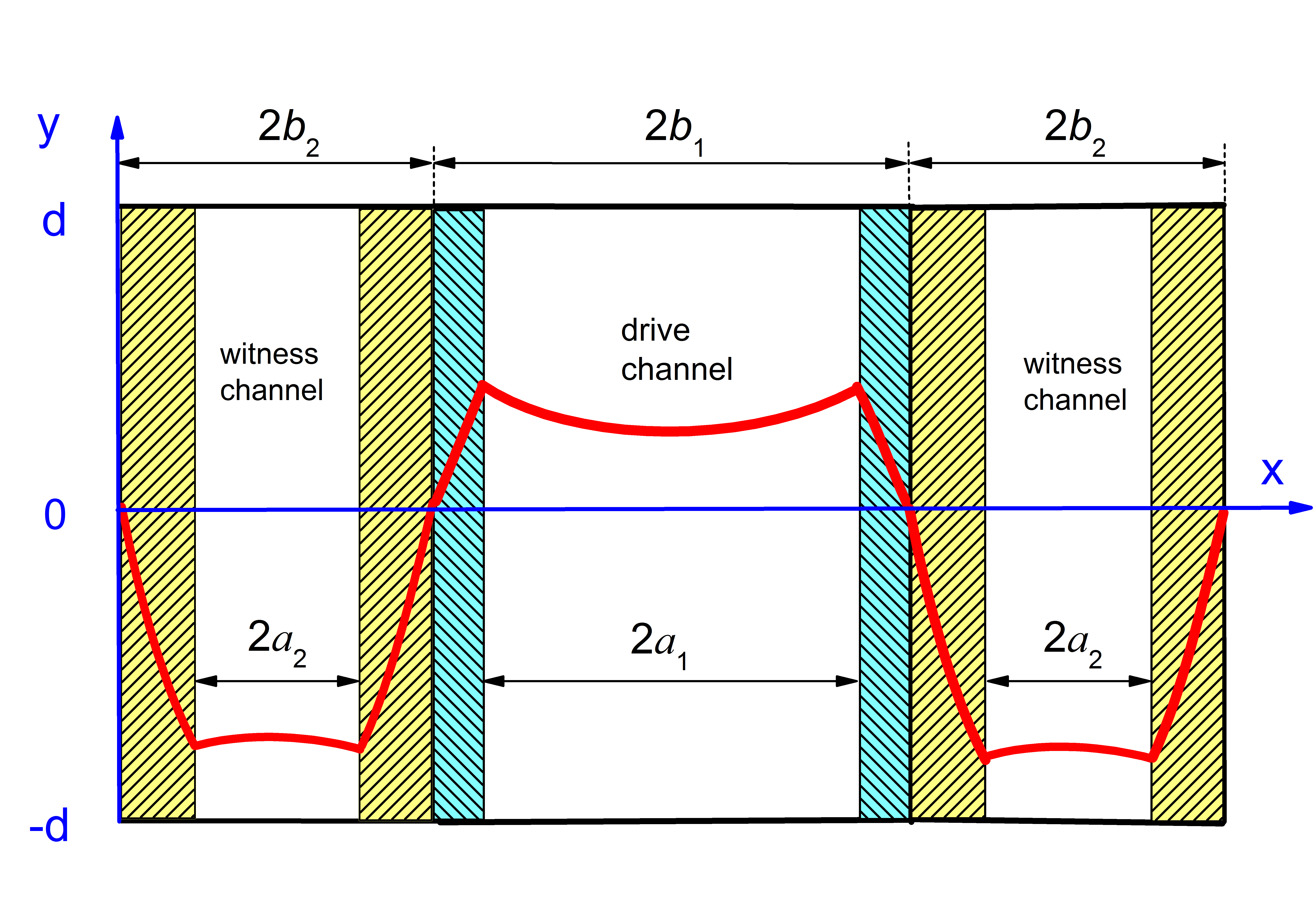
We now study a symmetric, rectangular dielectric loaded unit consisting of a central channel bordered by two narrow side channels; four slabs of dielectric are used, as in Fig. 1. One or more drive bunches can traverse the central channel and thereby set up intense wakefields that will accelerate witness bunches located in the narrow side channels. This device is essentially a symmetrized version of a two-beam rectangular DWA Shchelkunov et al. (2012) that has been operated successfully.
This accelerating module will have an elevated transformer ratio if the side channels are narrower than the drive channel (Fig.1) and the mode, as shown, is excited. Separation of drive and witness channels allows achieving both high accelerating gradient and elevated transformer ratio . The requirement is needed for efficient operation of a dielectric wakefield high energy accelerator system, to minimize the number of drive beam segments needed to achieve a given final test beam energy; the cost of such an accelerator tends to scale as Shiltsev (2015); Shchelkunov (2015). The geometry we have chosen to study also offers an opportunity to deal with the problem of the beam breakup (BBU) instability Li et al. (2014) which will limit the gradient that can be obtained in a collinear DWA. If it is “tall”, a rectangular DWA structure excited by a “sheet” bunch has weaker transverse wakefields (none in the 2D limit) than the cylindrical DWA Tremaine et al. (1997), thereby providing a certain remediation of the BBU. A sheet-type witness bunch configuration (also referred to as “flat” or “pancake”) is also potentially useful in a Collider.
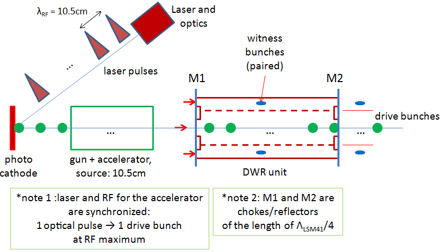
We begin by describing a rectangular three-channel DWA unit that can accommodate sheet-type bunches. It can be excited by a single high-charge drive bunch. Following that is a discussion of how the performance of this unit might be improved if a section of it is enclosed by reflectors, which we then refer to as a dielectric wakefield resonator (DWR) Marshall et al. (2001b); Sotnikov et al. (2006); Kiselev et al. (2006). This DWR unit can be excited by a train of low-charge drive bunches that will cause the accumulation of an intense wakefield inside the resonator structure. At the moment when, after reflecting from the resonator exit, the wakefield returns to the resonator entrance, the next bunch is injected into the resonator entrance. The length of the resonator is also chosen to be a multiple of half the desired wakefield wavelength by design of the dielectric liners. Fig.2 is a schematic showing how the DWR might be used as a component of a high energy wakefield linear accelerator. The train of drive bunches is made by a macropulse of laser pulses, incident upon a photocathode, that occur near the peaks of the RF field in the gun and the drive bunch accelerator system. The advantage of the DWR is that a train of drive bunches spaced so as to enhance the wakefield by coherent superposition will suppress unwanted wakefield modes which can decrease R; using multiple bunches to build up the wakefield also may present less demand on the injection RF gun and accelerator. Examples follow in the next two sections.
II The Three-Channel Rectangular DWA
Small dimensions of the unit will favor high gradients, so as an example, we consider a unit with the following specifications (Table 1):
| frequency of design mode | |
|---|---|
| accl. channel dimensions | |
| drive channel dimensions | |
| structure height | |
| slab-1 thickness | |
| slab-2 thickness | |
| slab-3 thickness | |
| slab-4 thickness | |
| slab relative dielectric constant | |
| bunch dimensions | |
| (box distribution) | |
| drive bunch energy | |
| drive bunch charge | |
| drive bunch number | |
| drive bunch center location, |
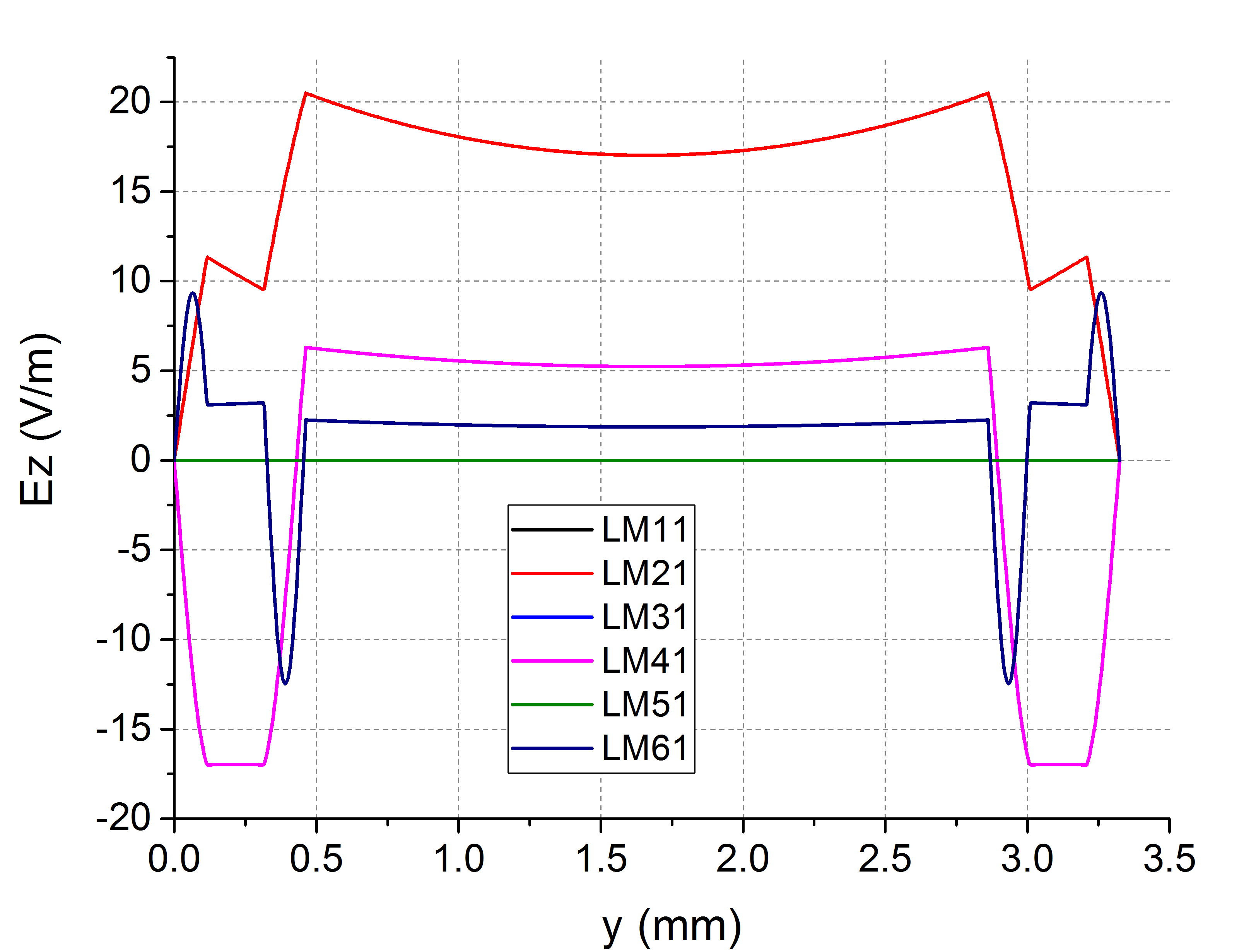
The wavelengths of the modes ( is the -subscript, is the -subscript), are as follows: . Profiles of some of these modes are shown in Fig.3. The has a desirable whereas the other modes do not.
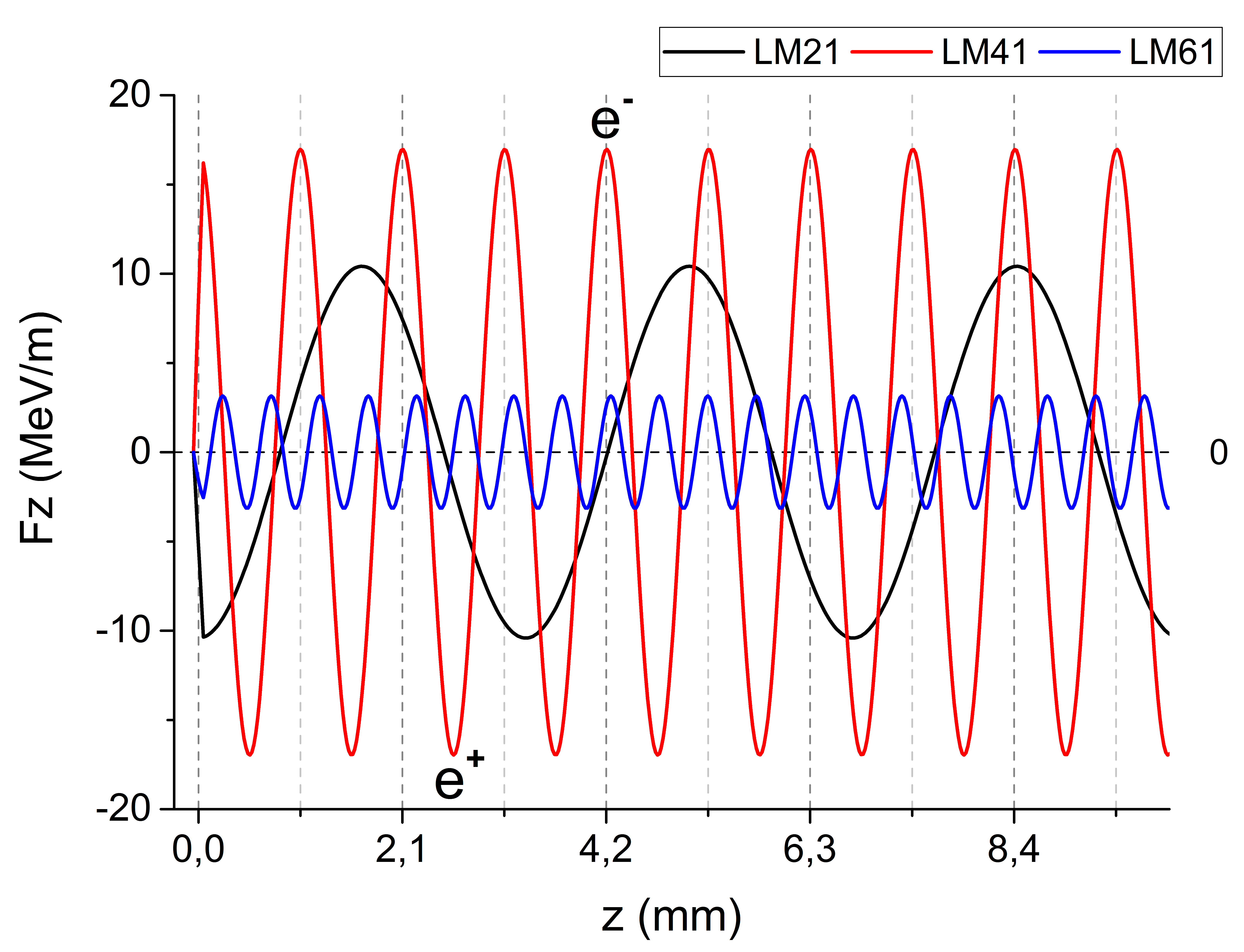
To determine the behavior of this structure, we, using the analytical theory for excitation of multi-zone dielectric structures by electron bunches Wang and Hirshfield (2006); Sotnikov et al. (2008), have made analytical computations of the wakefield excitation in a waveguide with the cross-section given by Table 1, set up by the passage of a single “point-like” drive bunch as specified therein. The result is shown in Fig.4. This electron bunch excites only modes with symmetric transverse profile of the in the drive channel. The desired operating mode with symmetric profile in all three channels is which has a frequency of . For this single bunch, analytic computation finds that an axial wakefield force on a test electron of appears in the witness channel, achieving computed for the average decelerating force acting upon the drive bunch. Fig.4 shows that for this design there is competition between the desired mode and the unwanted mode. However, a witness bunch can be located at a position where the mode amplitude dominates the others, as shown in the figure at axial positions . Although modes competing with can be reduced in importance by using a long train of drive bunches, the trailing bunches can be destabilized by head-to-tail deflections after moving a a certain distance: this problem motivates the use of the DWR.
III The Three-Channel Rectangular Dielectric Wakefield Resonator (DWR)
The use of cavity resonators to accelerate particles is well-established physics. By injecting several drive bunches spaced by a multiple of the desired mode and reflecting the wakefield radiation from tuned mirrors, we can suppress the buildup of unwanted non-resonant radiation in a DWR. Given favorable resonator , fields can accumulate in the compact resonator section to high amplitude. The theory and experimental operation of a single-channel DWR was reported several years ago Sotnikov et al. (2006); Kiselev et al. (2006); Onishchenko et al. (2006). If the accelerator providing the drive bunch train were to be powered by a RF source, the length of a resonator that holds one bunch would be and include resonant periods of the mode.
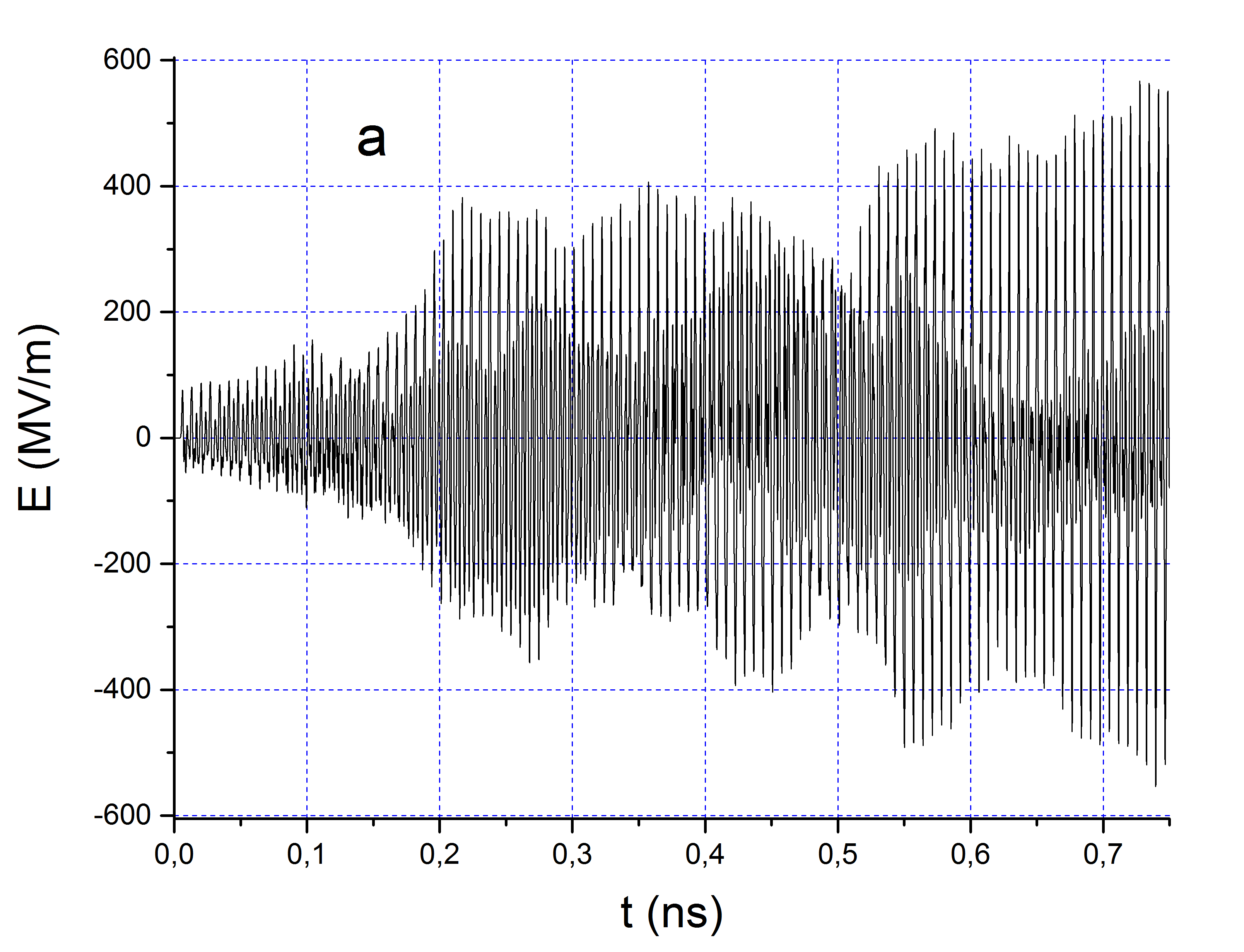
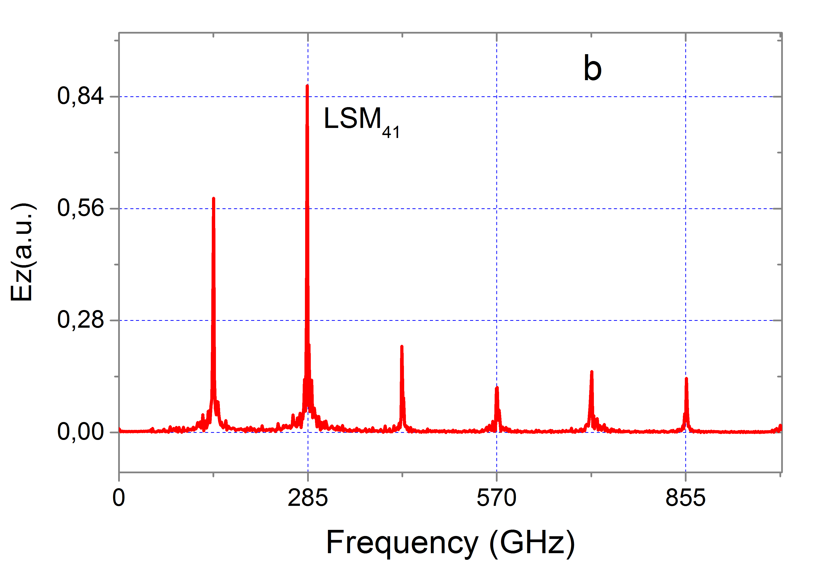
To study the performance of a three channel device configured as a resonator we use the CST Studio code, but because the time required for computation of a unit that would be suitable in practice is too large, a model structure was tested using a tight bunch spacing in a short resonator. A PIC simulation taking the resonator length to be (to hold bunches at a time) with bunch spacing of (two wakefield periods) is shown in Fig.5. The resonator is therefore half-wavelengths of the desired mode in length. A peak accelerating field in the resonator is obtained at its input (Fig.5a) after injecting bunches. The wakefield spectrum (Fig.5b) shows the mode prevails for this shortened device, so we can expect to obtain high transformer ratio here, as was the case for the simple waveguide computation (competing modes with appreciable power would lower the because of unfavorable profiles). The mode is preferentially excited because of the destructive interference of the non-resonant modes in the designed resonator. The spectrum peak to the left of the mode is an artifact that is caused by the choice of drive bunch spacing of twice the period. The field within the resonator can be represented as two oppositely-directed interfering waves, so the gradient available for accelerating a given bunch is one-half the gradient of the standing wave. The witness bunch is to be accelerated by the co-moving component of the standing wave wakefield.
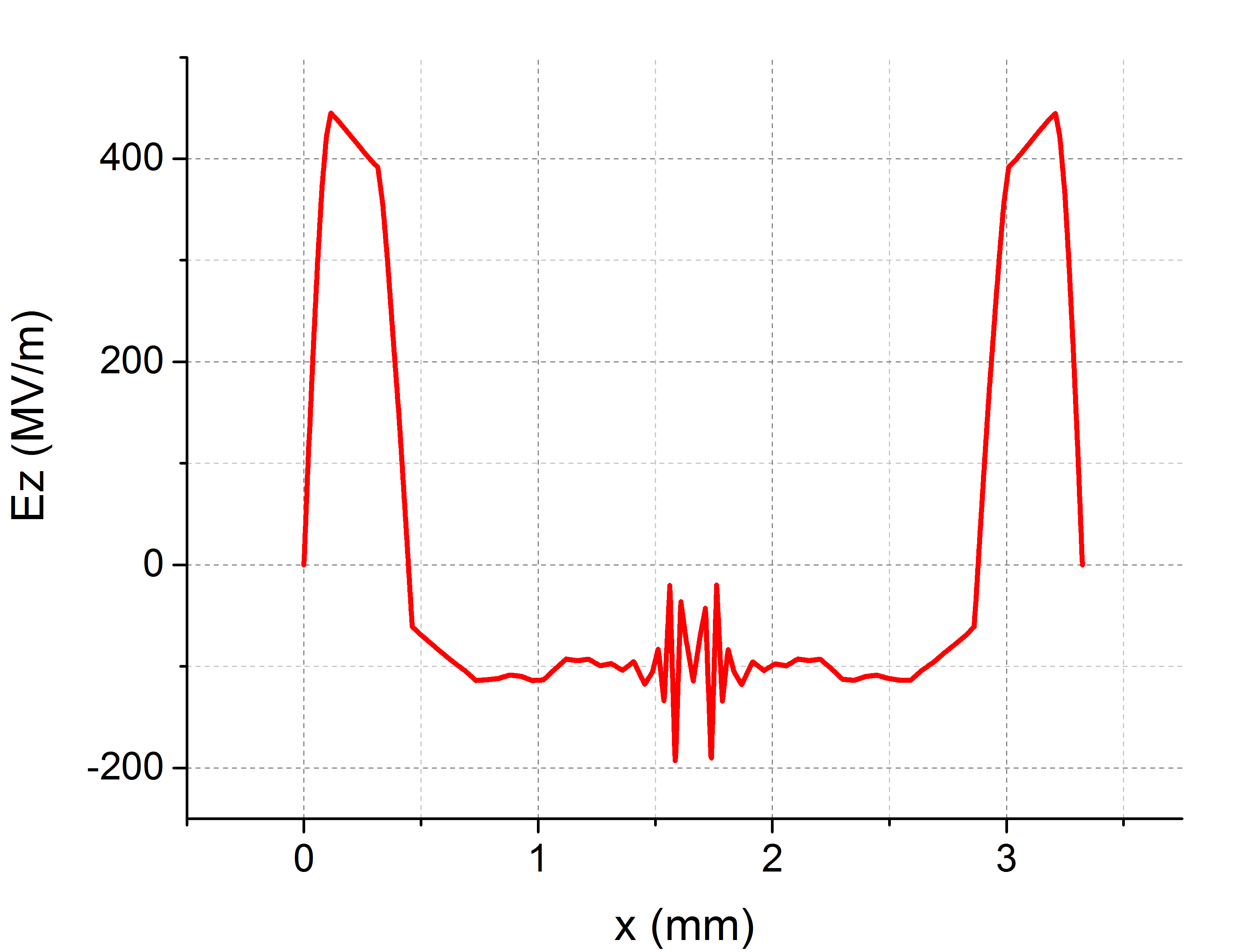
A profile of the field inside the resonator after injection of the last drive bunch is displayed in Fig.6. The profile is similar to that of the mode shown in Fig.3, indicating that a particle placed there will move under the influence of that mode and the system will enjoy an elevated transformer ratio.
This CST Studio simulation takes the wakefield to be perfectly reflected from the ends of the resonator. However, this can allow the accumulation of radiation from unwanted wakefield modes that have different frequencies as well as broadband radiation emitted from the injection of the drive bunches into the waveguide Onishchenko et al. (2002). The use of tuned Bragg dielectric multilayer mirrors would allow only the wanted mode to be reflected from the ends of the resonator.
In the present study using CST Studio we can examine the shape of a bunch just before it exits the resonator (parameters as specified in Table I) at the time when the resonator wakefield is largest. We have found no deterioration in the shape of the fortieth bunch. In practice, an actual DWR would be much longer and should have a large but finite Q Onishchenko et al. (2006), so this result should be revisited.
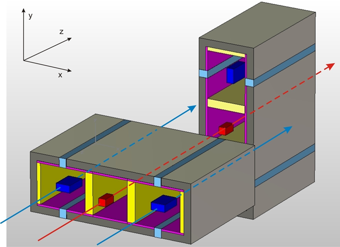
The choice of the best drive bunch shape is open to further study. A charge profile that is flattened along the y-axis (see Fig.1) and extends a half--period along the z-axis might be suitable. However, a small circular cross-section “point-like” drive bunch may also be used, in which case, if the orientation of the tall resonators along the beamline is alternated by around the z-axis, it should be possible to obtain dynamical stabilization of the drive bunch train, because it is found that when expanding the forces about a small region including the z-axis in the drive channel at the drive bunch location, there results transverse forces , a quadrupole-like effect Marshall et al. (2009) that obtains despite the different height and width dimensions of the resonator. Fig.7 shows how this might be implemented to obtain dynamical stability for the drive bunch.
IV Conclusions
A two-beam three channel DWA has been described and shown to be a promising accelerator component for electrons and positrons, combining high gradient operation and elevated transformer ratio with the possibility of improved bunch stability when configured as a resonator. Additional computational and experimental work, together with investigation of how well dielectrics can survive in an accelerator environment Shchelkunov et al. (2016), are needed to establish the utility of this concept.
References
- Gai et al. (1988) W. Gai, P. Schoessow, B. Cole, R. Konecny, J. Norem, J. Rosenzweig, and J. Simpson, “Experimental demonstration of wake-field effects in dielectric structures,” Physical Review Letters 61, 2756–2758 (1988).
- Rosing and Gai (1990) M. Rosing and W. Gai, “Longitudinal- and transverse-wake-field effects in dielectric structures,” Physical Review D 42, 1829–1834 (1990).
- Ng (1990) King-Yuen Ng, “Wake fields in a dielectric-lined waveguide,” Physical Review D 42, 1819–1828 (1990).
- Park and Hirshfield (2000) S. Y. Park and J. L. Hirshfield, “Theory of wakefields in a dielectric-lined waveguide,” Physical Review E 62, 1266–1283 (2000).
- Power et al. (2000) J. G. Power, M. E. Conde, W. Gai, R. Conecny, P. Schoessow, and A. D. Kanareykin, “Measurements of the longitudinal wakefields in a multimode, dielectric wakefield accelerator driven by a train of electron bunches,” Phys. Rev. ST Accel. Beams 3, 101302 (2000).
- Baturin and Zholents (2017) S.S. Baturin and A. Zholents, “Upper limit for the accelerating gradient in the collinear wakefield,” Phys. Rev. ST Accel. Beams 20, 061302 (2017).
- Zhang et al. (1997) T-B. Zhang, J. L. Hirshfield, T. C. Marshall, and B. Hafizi, “Stimulated dielectric wake-field accelerator,” Physical Review E 56, 4647–4655 (1997).
- Xiao et al. (2001) Liling Xiao, Wei Gai, and Xiang Sun, “Field analysis of a dielectric-loaded rectangular waveguide accelerating structure,” Physical Review E 65, 016505 (2001).
- Marshall et al. (2001a) T. C. Marshall, Changbiao Wang, and J. L. Hirshfield, “Femtosecond planar electron beam source for micron-scale dielectric wake field accelerator,” Phys. Rev. ST Accel. Beams 4, 121301 (2001a).
- Marshall et al. (2002) T. C. Marshall, J-.M. Fang, and J. L. Hirshfield, “Theory for wake fields and bunch stability in planar dielectric structures,” in Advanced Accelerator Concepts: Tenth Workshop. AIP Conf. Proc., Vol. 647, edited by C. E. Clayton and P. Muggly (AIP, New York, 2002) pp. 527–541.
- Wang et al. (2004) Changbiao Wang, J. L. Hirshfield, J.-M. Fang, and Thomas C. Marshall, “Strong wakefields generated by a train of femtosecond bunches in a planar dielectric microstructure,” Phys. Rev. ST Accel. Beams 7, 051301 (2004).
- Yoder and Rosenzweig (2005) R. B. Yoder and J. B. Rosenzweig, “Side-coupled slab-symmetric structure for high-gradient acceleration using terahertz power,” Phys. Rev. ST Accel. Beams 8, 111301 (2005).
- Shchelkunov et al. (2012) S.V. Shchelkunov, T.C. Marshall, G. Sotnikov, J.L. Hirshfield, , Wei Gai, M. Conde, J. Power, D. Mihalcea, and Z. Yusof, “Comparison of experimental tests and theory for a rectangular two-channel dielectric wakefield accelerator structure,” Phys. Rev. ST Accel. Beams 15, 031301 (2012).
- Wang and Hirshfield (2006) Changbiao Wang and J. L. Hirshfield, “Theory for wakefields in a multizone dielectric lined waveguide,” Phys. Rev. ST Accel. Beams 9, 031301 (2006).
- Pincherle (1944) L. Pincherle, “Electromagnetic waves in metal tubes filled longitudinally with two dielectrics,” Physical Review 66, 118–130 (1944).
- Sotnikov et al. (2006) G. V. Sotnikov, I. N. Onishchenko, and T. C. Marshall, “3D analysis of wake field excitation in a dielectric loaded rectangular resonator,” in Advanced Accelerator Concepts: Workshop. AIP Conf. Proc., Vol. 877, edited by Manoel Conde and Catherine Eyberger (American Institute of Physics, New York, 2006) pp. 888–894.
- Shiltsev (2015) V. Shiltsev, “On the future high energy colliders,” ArXiv e-prints (2015), presentation at the DPF 2015 Meeting of the American Physical Society Division of Particles and Fields, Ann Arbor, Michigan, August 4-8, 2015, arXiv:1509.08369v1 [physics.acc-p] .
- Shchelkunov (2015) Sergey Shchelkunov, “High transformer ratio of multi-channel dielectric wakefield structures and real-time diagnostic for charging and damage of dielectrics,” (2015), presentation at the the 2nd European Advanced Accelerator Concepts Workshop, La Biodola, Isola d’Elba, Italy, 13-19 September 2015.
- Li et al. (2014) C. Li, W. Gai, C. Jing, J.G. Power, C.X. Tang, and A. Zholents, “High gradient limits due to single bunch beam breakup in a collinear dielectric wakefield accelerator,” Phys. Rev. ST Accel. Beams 17, 091302 (2014).
- Tremaine et al. (1997) A. Tremaine, J. Rosenzweig, and P. Schoessow, “Electromagnetic wake fields and beam stability in slab-symmetric dielectric structures,” Physical Review E 56, 7204–7216 (1997).
- Marshall et al. (2001b) T. C. Marshall, J. M. Fang, J. L. Hirshfield, and S. Y. Park, “Multi-mode, multi-bunch dielectric wake field resonator accelerator,” in Advanced Accelerator Concepts: Ninth Workshop. AIP Conf. Proc., Vol. 569, edited by P. Colestock and S. Kelley (AIP, New York, 2001) pp. 316–325.
- Kiselev et al. (2006) V. A. Kiselev, A. F. Linnik, T. C. Marshall, I. N. Onishchenko, N. I. Onishchenko, G. V. Sotnikov, and V. V. Uskov, “Wakefield excitation by a sequence of electron bunches in a rectangular waveguide lined with dielectric slabs,” in Advanced Accelerator Concepts: Workshop. AIP Conf. Proc., Vol. 877, edited by Manoel Conde and Catherine Eyberger (AIP, New York, 2006) pp. 851–858.
- Sotnikov et al. (2008) G.V. Sotnikov, I.N. Onishchenko, J.L. Hirshfield, and T.C. Marshall, “A five-zone two-channel dielectric wakefield structure for two beam acceleration experiments at Argonne National Laboratory,” Problems of Atomic Science and Technology. Series: Nuclear Physics Investigations, 49, 148–152 (2008).
- Onishchenko et al. (2006) Nikolay I. Onishchenko, Gennadij V. Sotnikov, and Thomas C. Marshall, “Amplitudes and spectra of wake fields in a planar dielectric resonator with finite q-factor,” in Advanced Accelerator Concepts: Workshop. AIP Conf. Proc., Vol. 877, edited by Manoel Conde and Catherine Eyberger (AIP, New York, 2006) pp. 866–872.
- Onishchenko et al. (2002) I. N. Onishchenko, D. Yu. Sidorenko, and G. V. Sotnikov, “Structure of electromagnetic field excited by an electron bunch in a semi-infinite dielectric-filled waveguide,” Phys. Rev. E 65, 066501 (2002).
- Marshall et al. (2009) T. C. Marshall, G. V.Sotnikov, S. V. Shchelkunov, and J. L. Hirshfieldd, “Analysis of a symmetric terahertz dielectric-lined rectangular structure for high gradient acceleration,” in Advanced Accelerator Concepts: Workshop. AIP Conf. Proc., Vol. 1086, edited by C. B. Schroeder, W. Leemans, and E. Esarey (AIP, New York, 2009) pp. 421–426.
- Shchelkunov et al. (2016) S. V. Shchelkunov, T.C. Marshall, and Hirshfield, “Real-time diagnostic for charging and damage of dielectrics in accelerators,” Nuclear Instruments and Methods in Physics Research Section A: Accelerators, Spectrometers, Detectors and Associated Equipment 829, 194–198 (2016).