Dynamics of Relativistic Shock Waves Subject to a Strong Radiation Drag: Similarity Solutions and Numerical Simulations
Abstract
We examine the effect of Compton drag on the dynamics of a relativistic shock wave. Similarity solutions describing a radiation-supported shock are obtained for certain profiles of the external radiation intensity and the density of the unshocked ejecta, and are compared with 1D numerical simulations of a blast wave expanding into an ambient medium containing isotropic seed radiation. Both the analytic model and the simulations indicate that under realistic conditions the radiation drag should strongly affect the dynamics and structure of the shocked layer. In particular, our calculations show significant strengthening of the reverse shock and weakening of the forward shock over time of the order of the inverse Compton cooling time. We conclude that the effect of radiation drag on the evolution of the emitting plasma should affect the resultant light curves and, conceivably, spectra of the observed emission during strong blazar flares.
I Introduction
High-energy emission is a defining property of compact relativistic astrophysical sources. There is ample evidence that the emission is produced in relativistic outflows launched by an accreting black hole or a magnetar. The interaction of these outflows with their environments results in formation of expanding cocoons and shocks, that decelerate the flow and lead to lower energy emissions over a large range of scales, e.g., afterglow emission in GRBs and radio lobes in AGNs and micro-quasars. In certain circumstances the relativistic jets interact also with ambient radiation fields emitted by the surrounding gas. This interaction can considerably alter the dynamics of dissipative fluid shells at relatively small scales, and is likely to be the origin of the variable gamma-energy emission observed in certain classes of high-energy sources.
Direct evidence for such interactions is found in blazars, where the properties of the ambient radiation field can be measured. This radiation is contributed primarily by the accretion disk around the black hole, by gaseous clouds in the broad line region (BLR) and, at larger scales, by a dusty molecular torus Joshi, Marscher, and Bottcher (2014); Sikora et al. (2009). The conventional wisdom has been that the high-energy emission seen in powerful blazars results from inverse Compton scattering of ambient seed photons by non-thermal electrons accelerated in dissipative regions in the jet Dermer and Schlickeiser (1993); Sikora, Begelman, and Rees (1994); Blandford and Levinson (1995); Ghisellini and Madau (1996). In most early works the dynamics of the radiating fronts is not computed in a self-consistent manner. More recent works incorporated realistic shock models to compute light curves of flared emission Joshi, Marscher, and Bottcher (2014); Joshi and Bottcher (2011). However, the effect of the radiation drag on the structure and dynamics of the shock has been neglected.
In this paper we construct a model for the dynamics of a relativistic shock wave in the presence of intense radiation field. In section II we derive the governing equations of a radiation-supported shock. In section III we present self-similar solutions, obtained under several simplifying assumptions regarding the properties of the ejecta and the intensity profile of the external radiation field, and study the dependency of the evolved structure on the magnitude of the radiation drag. In section IV we present results of numerical simulations of a uniform, spherical ejecta propagating through an ambient medium containing isotropic seed radiation. The simulations enable analysis of the temporal evolution from the initial stage under more realistic conditions. While the analysis is motivated by the application to blazars, mainly because there we have sufficient information to asses the conditions in the source, it might also be relevant to other high-energy astrophysical systems.
II Radiation-supported shock model
Quite generally, the collision of relativistic fluid shells leads to the formation of a double-shocked layer. Some examples include the interaction of expanding ejecta with an ambient medium and collision of fast and slow shells (internal shocks). In the absence of external forces, the dynamics of the double-shock system is dictated solely by the properties of the unshocked media. In the presence of external radiation field, the shocked layers are subject to radiation drag that can alter the dynamics significantly. When the drag is strong enough it should lead to a weakening of the forward shock and strengthening of the reverse shock. In essence, the compression of the shocked ejecta (or the shocked plasma of the fast shell in case of internal shocks) is supported by the radiation pressure imposed on it. Thus, as a simple approximation one can ignore the entire region beyond the contact discontinuity, and obtain solutions describing a radiation-supported shock. This is the treatment adopted in section III below. The validity of this approximation is checked in section IV using numerical simulations.
Below we adopt the following notation: The velocities of the reverse shock and the contact surface are denoted by and , respectively, and the corresponding Lorentz factors by and . Plasma quantities are denoted by lower case letters, and subscripts and refer to the unshocked and shocked ejecta, respectively.
II.1 Flow equations
The dynamics of a relativistic fluid is governed by the continuity equation,
| (1) |
and energy-momentum equations,
| (2) |
here expressed in terms of the energy-momentum tensor
| (3) |
where , and are, respectively, the proper density, pressure and specific enthalpy, is the fluid 4-velocity, and is the metric tensor, here taken to be the Minikowsky metric . The source term on the right hand side of Eq. (2) accounts for energy and momentum exchange between the fluid and the ambient radiation field, and is derived explicitly below. The above set of equations must be augmented by an equation of state. We adopt the relation
| (4) |
with for a relativistically hot plasma and for sub-relativisric temperatures.
We shall restrict our analysis to spherical (or conical) flows, and adopt a spherical coordinate system . Equations (1) and (2) for the shocked fluid then reduce to:
| (5) | |||
| (6) | |||
| (7) |
here denotes the convective derivative.
A common approach is to seek solutions of Eqs. (5)-(7) inside the shocked layer, given the properties of the unshocked flows upstream of the forward and reverse shocks as input. The jump conditions at the forward and reverse shocks then serve as boundary conditions for the shocked flow equations. In addition, the fluid velocity and total momentum flux must be continuous across the contact discontinuity surface. In the approximate treatment adopted here, whereby the reverse shock is fully supported by radiation and the layer enclosed between the contact and the forward shock can be ignored, the location of the contact is fixed by the requirement that the total energy is conserved, given formally by Eq. (19) below.
II.2 Jump conditions at the reverse shock
For the range of conditions envisaged here the shocked plasma is optically thin. The shock, in this case, is collisionless, i.e., mediated by collective plasma processes (as opposed to radiation mediated shocks), and its width, roughly the skin depth, is much smaller than the Thomson length. Thus, the shock transition layer can be treated as a discontinuity in the flow parameters. The local jump conditions at the reverse shock can be expressed in terms of the local shock velocity , where is the shock radius at time , as Nakamura and Shigeyama (2006); Levinson (2010)
| (8) | |||
| (9) | |||
| (10) |
We shall henceforth assume that the unshocked medium is cold and set . The jump conditions at the forward shock can, in principle, be derived in a similar manner, but are redundant under our radiation-supported shock approximation.
II.3 Compton drag terms
Behind the shock electrons are heated and accelerated to relativistic energies. We denote the energy distribution of electrons there by , where is the dimensionless electron energy, as measured in the fluid frame. The total electron proper density is then given by , and the average energy and second energy moment by
| (11) |
If only the thermal electrons are taken into account one expects for plasma in rough equipartition, where is the Lorentz factor of the upstream flow, as measured in the shock frame, and it is assumed that . If the contribution of non-thermal electrons is substantial, then may be larger. Since the shocked electron plasma is relativistic we have .
The derivation of the source terms is given in Ref Golan and Levinson, 2015. In terms of the energy density of the radiation intercepted by the flow, , and the quantities defined above they can be expressed as
| (12) |
and
| (13) |
From Eqs. (7) and (13) it is readily seen that the deceleration time of the shocked fluid is given by , where is the inverse Compton cooling time of an electron having an energy , as measured in the fluid rest frame, and . Substantial deceleration occurs if is much shorter than the outflow time, . For convenience, we define the drag coefficient as
| (14) |
As noted above, for thermal electrons . If only the contribution of thermal electrons is accounted for, then
| (15) |
The energy loss term can now be expressed as:
| (16) |
To get an estimate of the value of anticipated in blazars, suppose that a fraction of the nuclear luminosity, erg/s, is scattered across the jet. The corresponding energy density of the radiation intercepted by the jet is roughly ergs cm-3, where is the radius in parsecs. From Eq. (15) one obtains . A more realistic estimate can be obtained using recent calculations of the ambient radiation intensity contributed by the various radiation sources surrounding a blazar jet Joshi, Marscher, and Bottcher (2014). It is found that for a prototypical blazar the intensity profile of radiation intercepted by the jet is flat up to a distance of about one parsec, with erg cm-3, followed by a gradual decline . For an internal shock produced by colliding shells, Equation (15) yields for the drag coefficient . Typically , implying significant drag on sub-parsec scales in blazars.
II.4 Global energy conservation
The change over time in the total energy of the shocked ejecta (or shocked fast shell) must equal the difference between the energy injected through the reverse shock and the energy radiated away through the contact. The energy accumulated behind the forward shock is neglected in our approximate treatment. The time change of the total energy per steradian of the shocked ejecta is
| (17) | |||||
where and are, respectively, the radii of the reverse shock and the contact surface, and , are the corresponding velocities. Integrating Eq. (6) from the shock, , to the contact, , one obtains:
| (18) | |||||
Combining Eqs. (17) and (18), using the jump condition (10) with (cold ejecta) and the relation , and recalling that the fluid velocity is continuous across the contact, viz., , yields
| (19) |
The first term on the right hand side accounts for the power incident through the reverse shock, the second term for work at the contact and the last term for radiative losses.
III Self-similar solutions
Similarity solutions describing the interaction of a relativistic shell with an ambient medium, in the absence of radiative losses, were derived in Ref Nakamura and Shigeyama, 2006, and their stability was subsequently analyzed Levinson (2009, 2010). Such solutions can be obtained for a freely expanding ejecta characterized by a velocity profile at time after the explosion, and a proper density of the form
| (20) |
where is a normalization constant, and is the corresponding Lorentz factor (it can be readily seen that the continuity equation is satisfied for this choice of and ). Self-similarity requires that the Lorentz factors of the forward shock, reverse shock and the contact discontinuity have a similar time evolution, viz., , , , where and are constants determined upon matching the solutions in region 1 (shocked ejecta) and region 2 (shocked ambient medium) at the contact discontinuityNakamura and Shigeyama (2006); Levinson (2010). For an ambient density profile of the form , the index is given by Nakamura and Shigeyama (2006); Levinson (2010)
| (21) |
In cases where the shocked plasma is subject to strong radiative losses it is still possible to obtain self-similar solutions provided the energy source term scales as (see Eq. (6) and (7)), that is, in Eq. (16) is constant. We shall henceforth make this assumption even though it implies a somewhat artificial intensity profile of the external radiation field. We note, however, that as long as the deceleration length is smaller than the radius of the shock these details are unimportant. This is confirmed by numerical simulations, presented in the next section.
As explained above, in the presence of a strong radiation drag the dynamics of the system is dictated by the interaction of the external radiation field with the shocked plasma enclosed between the contact and the reverse shock. To a good approximation one can then ignore the contribution of the forward shock to the overall dynamics. The evolution of the radiation-supported shock still satisfies , , but the index is now determined from global energy conservation, as will be shown below. Now, to order the trajectory of the reverse shock is given by
| (22) |
from which we obtain for the velocity of the ejecta crossing the shock: . The corresponding Lorentz factor is thus given, to the same order, by
| (23) |
and the density profile by
| (24) |
We adopt the similarity parameter introduced in Ref Blandford and McKee, 1976,
| (25) |
With this choice the reverse shock is located at , and the contact at . Following Ref. Nakamura and Shigeyama, 2006 we define the self-similar variables, , and , such that at the reverse shock they satisfy the boundary conditions . Upon solving the jump conditions (8)-(10), the shocked fluid quantities can be expressed in terms of the self-similar variables as
| (26) | |||
| (27) | |||
| (28) | |||
| (29) |
where the parameter is the only positive root of the polynomial equation
| (30) |
Upon substituting these relations into Eqs. (5)-(7), and using Eq. (16) with a constant drag coefficient, const 111More generally, can be taken to be any function of the similarity coordinate . In the presence of strong drag the width of the shocked layer is much smaller the its radius, hence we anticipate little variations in across it., we obtain the following set of equations for the self-similar variables:
| (31) | |||||
| (32) | |||||
| (33) | |||||
subject to the boundary conditions . These equations reduce to those derived in Ref. Nakamura and Shigeyama, 2006 in the special case . As can be seen, at the contact, , the Lorentz factor must satisfy , where for short we denote . This relation defines the limit of integration.
The self-similar equations involve two eigenvalues; the index and the location of the contact . Thus, two conditions are needed to find them. The first one is the relation
| (34) |
mentioned above. The second one is global energy conservation, Eq. (19). To order we have , and , from which we obtain
| (35) | |||||
and . To the same order one has . Substituting these results into Eq. (19) yields the constraint
| (36) | |||||
where .
III.1 Results
For a given choice of the drag coefficient we guess the value of and integrate Eqs. (31)-(33) from to the point at which Eq. (34) is satisfied. We then check if Eq. (36) is satisfied. If not, we change the value of and repeat the process until a solution satisfying all constraints is found. Sample profiles are shown in Fig. 1 for and different values of . The radiation free case () is shown for a comparison. It was computed using the full solution of the two-shock model described in Ref. Nakamura and Shigeyama, 2006. As seen, the width of the shocked layer, , decreases with increasing drag coefficient , as naively expected. Moreover, larger radiative losses lead to increased non-uniformity of the Lorentz factor and pressure in the shocked layer. The divergence of the density at the contact is a basic feature of the similarity solutions Levinson (2010) and occurs even in the absence of radiative losses (), as seen in the upper panel of Fig. 1.
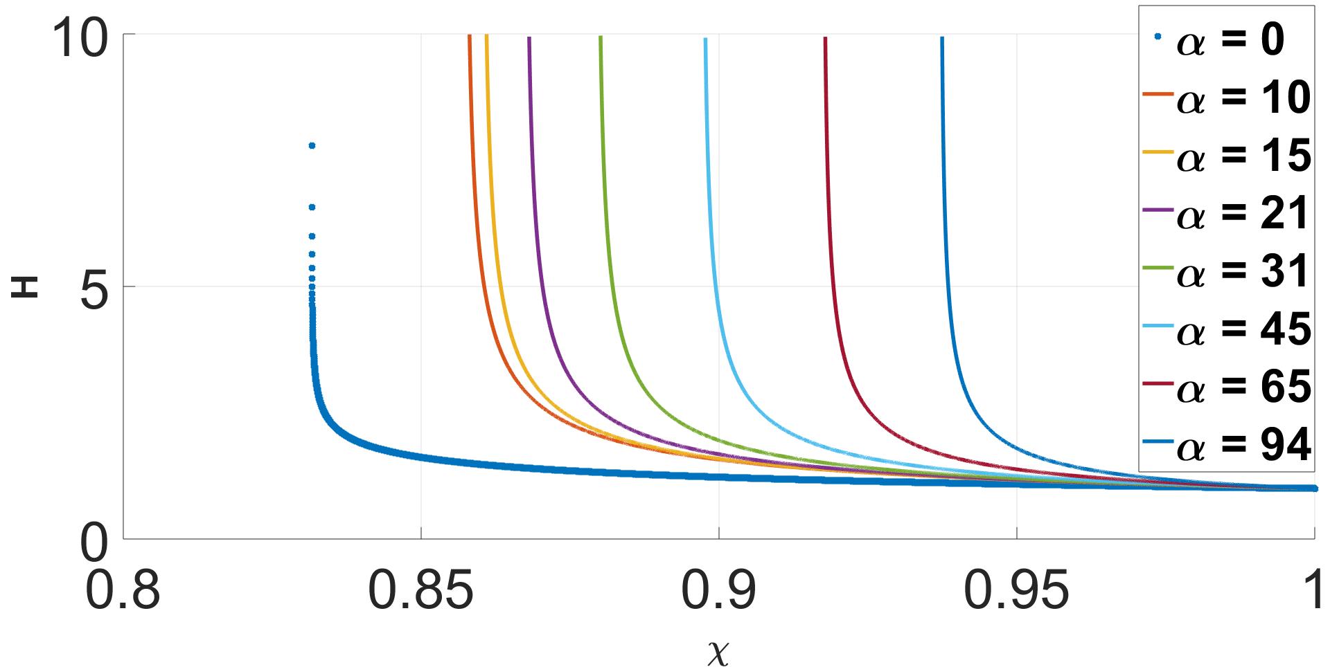
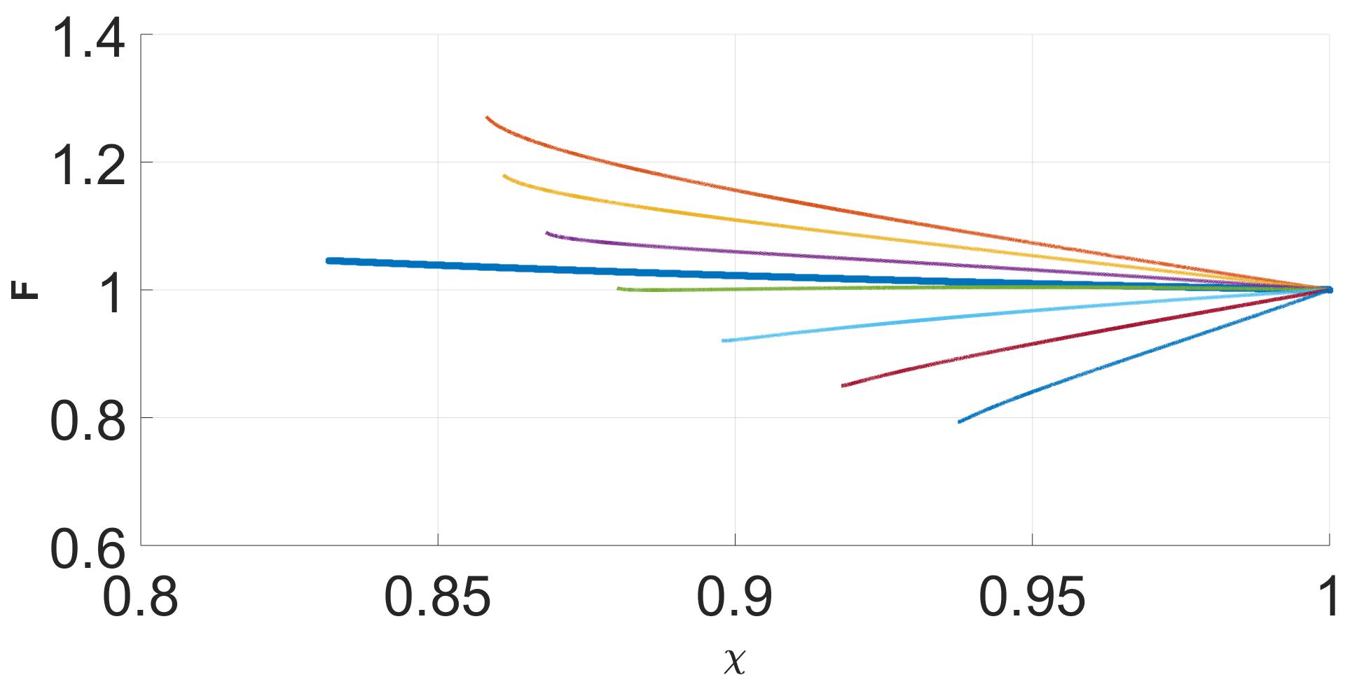
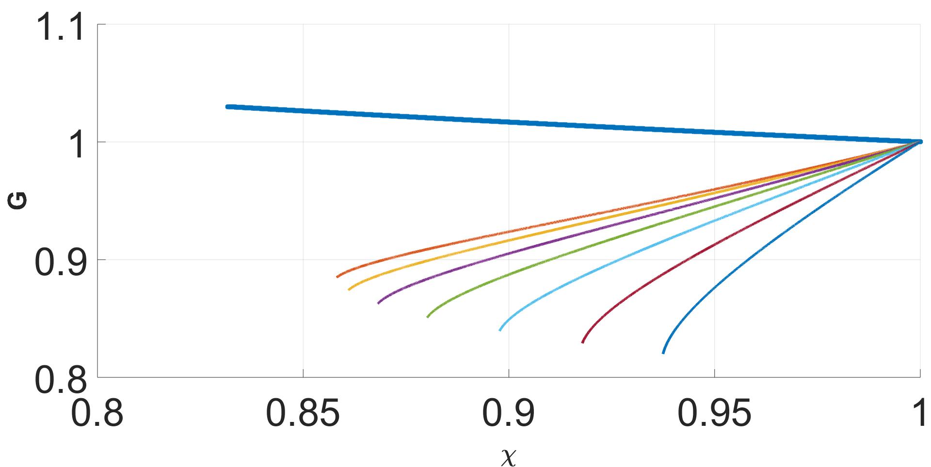
Figure 2 depicts the dependence of the index on . For a comparison, the value of obtained in the case for a blast wave propagating in a uniform density medium () is (see Eq. (21) with and ). The 4-velocity of the unshocked fluid, as measured in the frame of the reverse shock, is given by
| (37) |
and it is seen that the shock becomes substantially stronger as increases. Note that the power dissipated behind the shock, , increases roughly linearly with the index . At sufficiently large drag the entire power incident through the shock is radiated away, and the solution becomes independent of , as seen in Fig. 2. For our choice of parameters, specifically , this occurs at , for which and . We emphasize that this limit can be approached provided the Lorentz factor of the unshocked shell is sufficiently large. To be more concrete, Eq. (23) implies that as , while our analysis is valid only for . The Compton drag terms given in Eqs. (12) and (13) assume that the intensity of ambient radiation is highly beamed in the frame of the shocked fluid. Once decelerates to modest values, , the drag force is strongly reduced, ultimately becoming ineffective.

.
IV Numerical simulations
Numerical simulations were performed using the PLUTO code Mignone et al. (2007), that was modified to incorporate energy and momentum losses of the shocked plasma through Compton scattering. To clarify the presentation we adopted an external intensity profile of the form for which in Eq. (16) is constant. Over the deceleration scale this profile is a reasonable approximation to the flat profile expected in blazars Joshi, Marscher, and Bottcher (2014). We start with the basic spherical blast wave problem, releasing an ejecta with a uniform Lorentz factor into a stationary ambient medium (henceforth, quantities in the unshocked ejecta are designated by subscript ”e”). In our setup, both the ejecta and the ambient medium are taken to be uniform initially with a density ratio . The calculations are performed in ”simulation units” in which a fluid element traveling with a unit velocity (the speed of light) passes a unit of length per unit of time. The initial impact occurs at a radius and time . Due to the collision a double-shock structure forms and a shocked layer is created. As the simulation progresses the shocked layer widens and Compton drag is then applied on the shocked fluid contained between the forward and the reverse shocks. In order to suppress artificial transients created by abrupt changes we apply the radiation drag gradually by increasing the drag coefficient over time as . As our model assumes that the drag only affects the hot shocked plasma, the in-simulation drag is applied only in the region where the shocked fluid velocity is in the range , where is the 4-velocity of the unshocked ejecta. Preliminary runs have shown that for the radiation free case the shocked layer becomes sufficiently developed by (see Fig. 3), which is why the time constant for applying the radiation drag was chosen to be (by the drag reaches its maximum). For sufficiently high values of , the shocked layer decelerates and the reverse shock quickly becomes radiation-supported.
IV.1 Test case
As a check, we ran a test case with for the same setup described above, and compared the results with an analytic solution obtained under the thin shell approximation, whereby the shocked layers are assumed to be uniform. Under this approximation the shocked ejecta and shocked ambient medium have the same Lorentz factor, . In terms of the ratios and , the jump conditions, Eqs. (8) - (10), yield
| (38) |
and
| (39) |
where , and are functions of time. Solving these equations for the given initial conditions we obtain , at . As the ejecta expands, its density just upstream of the reverse shock evolves as . Solving the above equations at any given time using in Eq. (39), one obtains the Lorentz factor of the contact discontinuity, . The contact 4-velocity, , is shown as a dashed line in Fig. 3, along with the 4-velocity, pressure and density obtained from the simulations of the radiation free case (), at different times. As seen from Fig. 3, the jump at the shock agrees well with the analytic result.

IV.2 Simulation Results
For numerical reasons we were only able to run cases with modest values of , however these suffice to illustrate the main trends. Below we present results for . The initial conditions in all cases were set as described above.

Fig 4 displays snapshots of the plasma 4-velocity at different times for , showing the evolution of the entire structure. The -axis gives the distance from the reverse shock, , so that the reverse shock is located at at all times. The vertical red and blue lines indicate the location of the contact discontinuity and the forward shock , respectively. The deceleration of the shocked fluid, that leads to strengthening of the reverse shock and weakening of the forward shock is clearly seen. The radiation force gives rise to compression of the fluid near the contact which is communicated to the reverse shock and decelerates it (Fig. 5). The shocked layer gradually expands as time progresses, but initially less than in the case . The apparent sudden expansion of the shocked layer at late times (between and ) commences when the shock becomes mildly relativistic, as can be observed from Fig. 5. This is mainly due to the fact that the width of the shocked layer evolves with time as . We note that at such small Lorentz factors ( at ) our choice of Compton drag terms, that assume perfect beaming of the external radiation in the rest frame of the shocked fluid, overestimates the actual drag. In reality the drag is expected to be suppressed as the shocked fluid becomes mildly relativistic , so that the Lorentz factor of the reverse shock will eventually saturate once becomes sufficiently low.

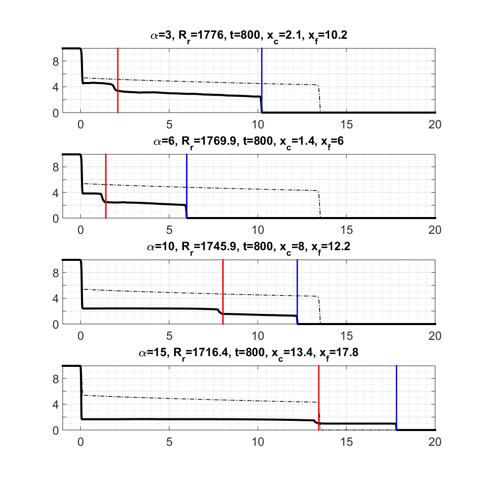
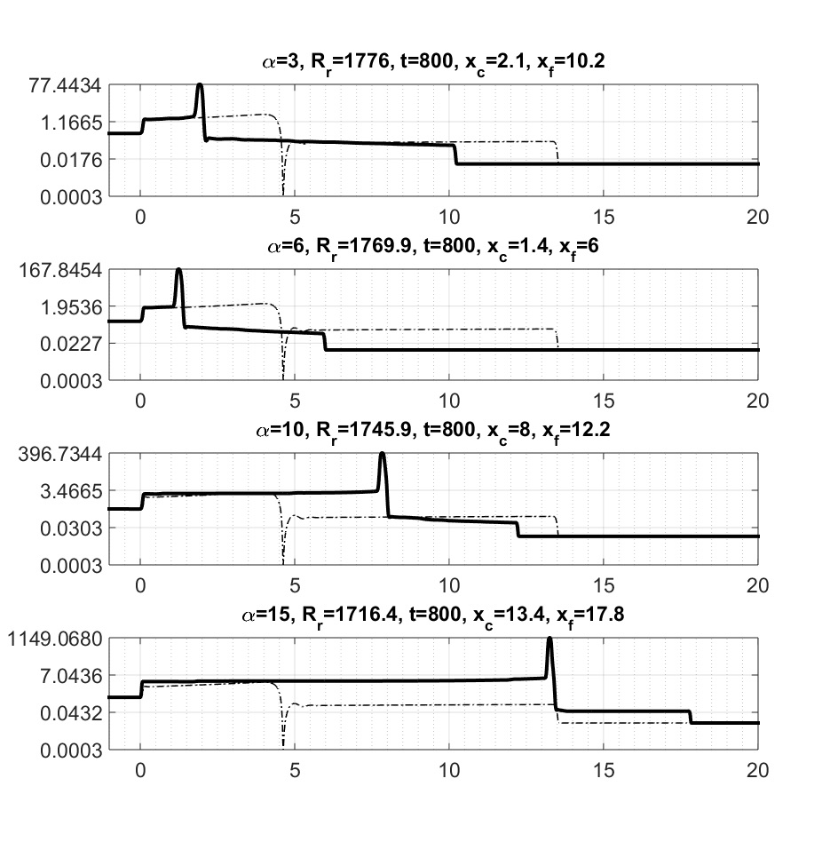
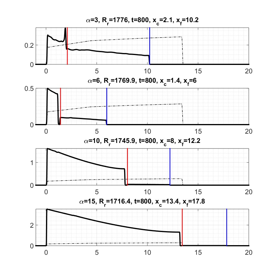
Figs 6 shows the profiles of the 4-velocity, pressure and density around the shock at the same simulation time, , for four values of as indicated in the figure label. The radius of the reverse shock at this time is also indicated for convenience, and it ranges from (or ) for to for . The result of the run with no radiation drag (), presented in Fig. 3, is plotted as a dotted-dashed line and is exhibited for a comparison. The contact location is found from the density profile, noticing that, as in the radiation-free case, the density peaks towards the contact and drops to a minimum right after it. In the resulting structure we see the transition from ”material - supported” to ”radiation-supported” shock; as is increased the forward shock becomes progressively weaker and ultimately negligible, while the reverse shock strengthens. This trend justifies the neglect of the shocked ambient pressure in the self-similar solution outlined in section III. Fig 6 confirms that, as long as the shock is sufficiently relativistic, the width of the shocked layer shrinks and the shocked fluid velocity decreases with increasing radiation drag, in accord with the self-similar solution. The widening of the shocked layer for the and cases stems from the transition to the mildly relativistic regime, as explained above. The increase of the pressure with increasing further indicates strong compression by the radiation force. The formation of the cold dense shell near the contact, seen in the lower left panel of Fig. 6, results from the rapid cooling of the compressed plasma.
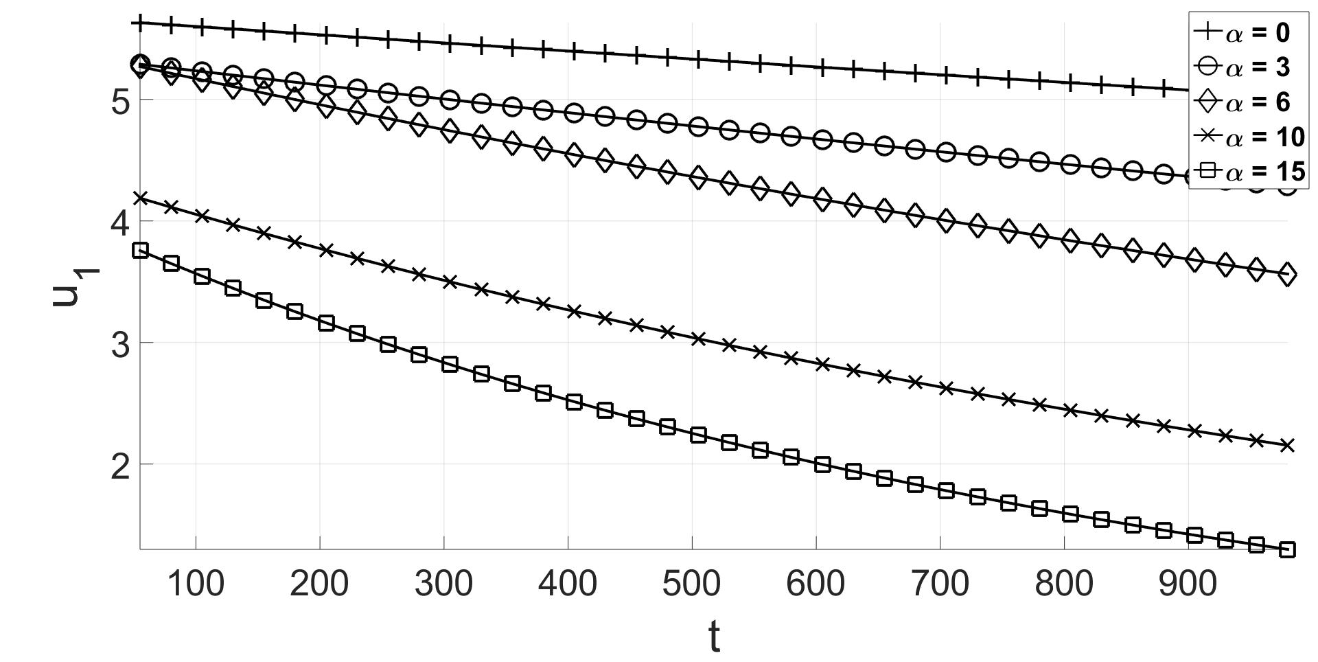
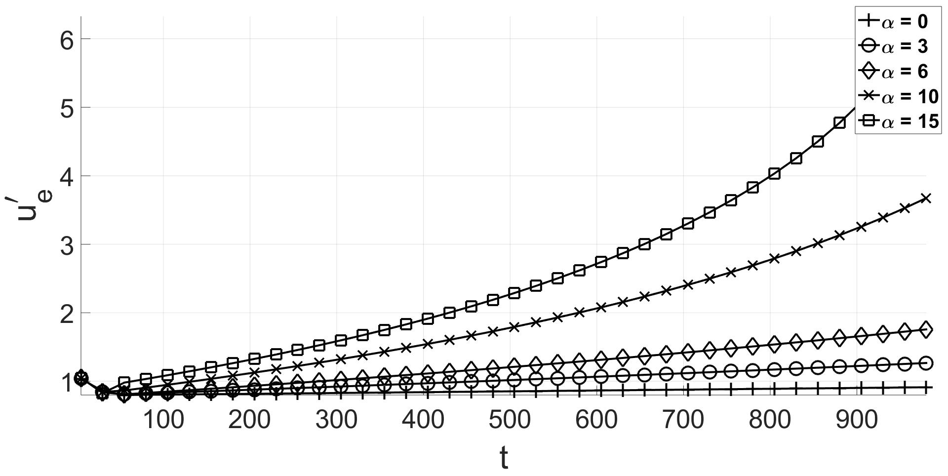
The left panel of figure 7 exhibits the evolution of the 4-velocity of the shocked ejecta. Gradual deceleration of the shocked flow over a timescale of the order of the cooling time is observed, as expected. The evolution of the 4-velocity of the unshocked ejecta with respect to the reverse shock is exhibited in the right panel of figure 7, indicating a substantial increase in shock efficiency with increasing .
V Summary and conclusions
We studied the effect of radiation drag on the dynamics of shocks that form in relativistic outflows. Such situations are expected in cases where the outflow propagates through a quasi-isotropic, ambient radiation field, on scales at which the inverse Compton cooling time is significantly shorter than the outflow expansion time. The observations of the continuum emission in blazars suggest that these conditions may prevail on sub-parsec to parsec scales in those objects.
For certain profiles of the external radiation intensity and the density of the unshocked ejecta we were able to find self-similar solutions of the radiation hydrodynamics equations, describing a radiation-supported shock. We also performed 1D numerical simulations of a uniform, spherical shell interacting with an ambient medium that contains cold gas and seed radiation. For that purpose we used the PLUTO code, that we modified to incorporate energy and momentum losses of the shocked plasma through Compton scattering.
In both, the analytical model and the simulation results, we find significant alteration of the shock dynamics when the ratio of dynamical time and Compton cooling time exceeds a factor of a few. Quite generally, substantial radiation drag leads to a faster deceleration, strengthening of the reverse shock and weakening of the forward shock. In the self-similar model with the 4-velocity of the upstream flow with respect to the shock increases from for a uniform ambient density profile and no radiation (), to about in the asymptotic limit of maximum efficiency (obtained for ). The Lorentz factor in the asymptotic limit evolves roughly as .
For numerical reasons the simulations were limited to modest values of , but show similar trends. The numerical experiments enabled us to follow the evolution of the system from the onset of fluid collision, and demonstrate the gradual strengthening of the reverse shock (and weakening of the forward shock) over time. For convenience we adopted intensity profile (of the seed radiation) that scales as , which is close to the flat profile obtained for blazars from detailed calculations. Since for a sufficiently large drag the deceleration scale is much smaller than the shock radius, the details of the intensity profile has little effect on the evolution. For our choice of constant drag coefficient, the deceleration continues indefinitely. In reality the drag will be strongly suppressed once the Lorentz factor of the emitting (shocked) fluid drops to values at which our ”beaming approximation” breaks down. In this regime strong cooling still ensues, but with little momentum losses. Our late time results for the cases and are therefore not reliable. More detailed calculations of the drag terms are needed to follow the evolution in the mildly relativistic regime.
The effect of radiation drag on the dynamics of the shock might have important implications for the resultant emission. On the one hand, the strengthening of the reverse shock leads to enhanced efficiency of internal shocks, in particular under conditions at which the reverse shock is sub-relativistic in the absence of external radiation. On the other hand, the deceleration of the shocked fluid, that emits the observed radiation, leads to a dramatic change in the beaming factor. This temporal change in beaming factor can significantly alter the light curves, particularly for observers viewing the source off-axis. Detailed calculations of variable emission from dragged shocks is beyond the scope of this paper, but our analysis suggests that detailed emission models, at least in blazars, should account for such effects.
Acknowledgements.
This research was supported by a grant from the Israel Science Foundation no. 1277/13.References
- Joshi, Marscher, and Bottcher (2014) M. Joshi, A. P. Marscher, and M. Bottcher, “Seed photon fields of blazars in the internal shock scenario,” Astrophys. J. 785, 132 (2014).
- Sikora et al. (2009) M. Sikora, L. Stawarz, R. Moderski, K. Nalewajko, and G. M. Madejski, “Constraining emission models of luminous blazar sources,” Astrophys. J. 704, 38–50 (2009).
- Dermer and Schlickeiser (1993) C. D. Dermer and R. Schlickeiser, “Model for the high-energy emission from blazars,” Astrophys. J. 416, 458 (1993).
- Sikora, Begelman, and Rees (1994) M. Sikora, M. C. Begelman, and M. J. Rees, “Comptonization of diffuse ambient radiation by a relativistic jet: The source of gamma rays from blazars?” Astrophys. J. 421, 153–162 (1994).
- Blandford and Levinson (1995) R. D. Blandford and A. Levinson, “Pair cascades in extragalactic jets. 1: Gamma rays,” Astrophys. J. 441, 79–95 (1995).
- Ghisellini and Madau (1996) G. Ghisellini and P. Madau, “On the origin of the gamma-ray emission in blazars,” Mon. Not. Roy. Ast. Soc. 280, 67–76 (1996).
- Joshi and Bottcher (2011) M. Joshi and M. Bottcher, “Time-dependent radiation transfer in the internal shock model scenario for blazar jets,” Astrophys. J. 727, 21 (2011).
- Nakamura and Shigeyama (2006) K. Nakamura and T. Shigeyama, “Self-similar solutions for the interaction of relativistic ejecta with an ambient medium,” Astrophys. J. 645, 431–4325 (2006).
- Levinson (2010) A. Levinson, “Relativistic rayleigh-taylor instability of a decelerating shell and its implications for gamma-ray bursts,” GApFD 104, 85–111 (2010).
- Golan and Levinson (2015) O. Golan and A. Levinson, “Blazar flares from compton dragged shells,” Astrophys. J. 809, 23 (2015).
- Levinson (2009) A. Levinson, “Convective instability of a relativistic ejecta decelerated by a surrounding medium: An origin of magnetic fields in gamma-ray bursts?” Astrophys. J. 705, L213–L216 (2009).
- Blandford and McKee (1976) R. D. Blandford and C. F. McKee, “Fluid dynamics of relativistic blast waves,” Phys. Fluids 19, 1130–1138 (1976).
- Note (1) More generally, can be taken to be any function of the similarity coordinate . In the presence of strong drag the width of the shocked layer is much smaller the its radius, hence we anticipate little variations in across it.
- Mignone et al. (2007) A. Mignone, G. Bodo, S. Massaglia, and et al., “Pluto: A numerical code for computational astrophysics,” Astrophys. J. Supp. 170, 228 (2007).