1\Yearpublication2014\Yearsubmission2014\Month0\Volume999\Issue0\DOIasna.201400000
XXXX
Chaos Control with Ion Propulsion
Abstract
The escape dynamics around the triangular Lagrangian point in the real Sun–Earth–Moon–Spacecraft system is investigated. Appearance of the finite time chaotic behaviour suggests that widely used methods and concepts of dynamical system theory can be useful in constructing a desired mission design. Existing chaos control methods are modified in such a way that we are able to protect a test particle from escape. We introduce initial condition maps in order to have a suitable numerical method to describe the motion in high dimensional phase space. Results show that the structure of initial condition maps can be split into two well-defined domains. One of these two parts has a regular contiguous shape and is responsible for long time escape; it is a long-lived island. The other one shows a filamentary fractal structure in initial condition maps. The short time escape is governed by this object. This study focuses on a low-cost method which successfully transfers a reference trajectory between these two regions using an appropriate continuous control force. A comparison of the Earth–Moon transfer is also presented to show the efficiency of our method.
keywords:
chaos – celestial mechanics – Earth – Moon – methods: numerical1 Introduction
Finite time chaotic behaviour is a common phenomenon in simple as well as in complex dynamical systems. Transient chaos in Hamiltonian dynamics appears as chaotic scattering (Bleher, Grebogi & Ott 1990) or half-scattering. This can later be thought as of escape or capture from or into a system. The finite time chaotic motion might proceed before the particle leaves the systems, say interacting with a scatter object, after which the irregular motion might cease.
Escape in simple dynamical systems has been extensively studied for roughly 25 years, for more details Ott (1993), Gaspard (1998), Contopulos (2004), Lai & Tél (2011). Theory of transient chaos states that finite time chaotic behaviour is related to the unstable periodic orbits and their stable and unstable manifolds in the phase space. In addition, one can construct numerically a well-defined fractal set in the phase space containing all the heteroclinic and homoclinic intersections of these manifolds as well as the unstable periodic orbits themselves. This fractal set is responsible for finite time chaotic behaviour. Some textbooks call this set the chaotic saddle, indicating its non-attracting nature.
The large number of studies dealing with escape dynamics shows the importance of this issue in dynamical astronomy. From the very simple systems such as the Hill approximation of the restricted three body problem(Simó & Stuchi 2000) or the Sitnikov problem (Kovács & Érdi 2009) to more complex dynamics, e.g. 3D model of barred galaxies (Contopoulos & Harsoula 2013; Jung & Zotos 2015; Maffione et al. 2015) or open star clusters (Ernst et al. 2015), one can find thorough investigations of finite time chaotic motion. Numerical simulations and also analytic computations have pointed out that the stable and unstable manifolds of the unstable periodic orbits play a crucial role in escape and capture (Ashtakov et al. 2004; Branicki & Wiggins 2010; Harsoula, Contopoulos & Efthymiopoulos 2015; Efthymiopoulos 2012). In computing the unstable periodic orbits and their manifolds, two suitable analytical methods are commonly used, one of these two is called the hyperbolic normal form (Moser 1958), and the other method is the normally hyperbolic invariant manifolds, introduced by Fenichel (1979). The chaotic saddle can also be constructed numerically by using the sprinkler method (Tél & Gruiz 2006).
At the end of the last century, researchers and engineers started to use the manifolds of periodic orbits to describe the dynamics of spacecraft manoeuvres and station keeping. The first method of constructing trajectories from the Earth to the Moon with lunar ballistic capture using low thrust spiral orbit was published by Belbruno (1987). Determining the weak stability boundary around the Moon was a great leap forward in the study of the low thrust orbits (Kevin, Belbruno & Topputo 2012). Although they used methods similar to ours, but without the conception of transient chaos (survival probability, escape rate, chaotic saddle, etc.) they did not give the explication to the phenomena they experienced (e.g. the magnitude of the thrusting, the stabilization of the motion).
The new dynamical system approach technique seemed to be an extremely useful application in space research, especially for precise orbit determination. Many recent space missions (Genesis (Howell et al. 1998), MAP (Bennett 1996) and Herschel-Planck (Rosa et al. 2005)) were designed using this so-called space manifold dynamics method (SMD) (Belló, Gómez & Masdemont 2010; Belbruno 2010).
The basic purpose of this technique is to find an orbit from one place to other, or keep a spacecraft at a given position around an unstable periodic orbit as cheaply as possible, i.e. with low energy/fuel requirements. SMD usually involves the approximation of the circular restricted problem of three bodies, say, for instance Sun-Earth-Spacecraft or Earth-Moon-Spacecraft systems, depending on current application.
There are five equilibrium points in an orbital configuration of two large bodies (in our case the Earth and the Moon), where the forces of gravity balance out; these are the Lagrangian points. There are five such points, labelled to . The , and (collinear) points are unstable, the and (triangular) points are linearly stable equilibrium points. The presence of a third large body, the Sun, destroys the stability of the Earth-Moon and points, but even though these points ( and ) are unstable, there are bounded regions around these points for either shorter or longer periods of time.
Although the attention in space manifold dynamics has been focused mainly in collinear points , , and because of their unstable nature (Celletti & Giorgili 1991) and vicinity to the Earth (, ). It can also be shown that escape from the vicinity of a natively stable libration point (e.g. or in the circular restricted three body problem (CRTBP)) is also governed by the unstable manifold of the chaotic saddle (Slíz, Süli & Kovács 2015) which encloses the regular islands surrounding the stable periodic orbit. This domain of the phase space, where the saddle and the remnants of the outermost KAM torus form a ”fat” fractal set, is responsible for the stickiness effect, one of the fundamental phenomena in Hamiltonian escape dynamics with mixed phase space (Contopoulos & Harsoula 2008; Tél & Lai 2008).
We started test particles close to the triangular libration point of the restricted three body problem (RTBP) and analyzed their short and long time dynamics in the presence of a third large body (the Sun), (RFBP).
As it has already been shown (Érdi et al. 2007; Freistetter 2006; Schwarz et al. 2009), the size and the position of the regular domain around the triangular points depend on several parameters such as the mass, eccentricity and the orbital position.
Starting a test particle from the vicinity of the , points in the RFBP is not a guarantee that this trajectory will be stable for a long time or that the particle will remain in the system. This is a consequence deriving from the general fact in Hamiltonian dynamics that the size of the regular tori in phase space decays exponentially with the degree of freedom of the system (Lichtenberg & Liebermann 1983; Altmann & Kantz 2007).
Our primary goal is to avoid the escape and to keep the test particle in a finite volume of the configuration space with minimal energy consumption. To do this we use the basic idea of chaos control where the main argument is that small changes along a chaotic orbit should be efficient enough to reach a desired performance of the system according to some criteria. The focus is on the expression ”small changes” that can be applied with success, since the chaos is naturally sensitive to small changes and therefore tiny perturbations are suitable for control and manipulation of the chaotic process (Boccaletti & Pucacco 2000). In this study, a slightly modified chaos control method is used which is suitable for our purposes. We construct the stable manifold of the chaotic saddle numerically for a given state of the phase space, called initial condition map (ICM) (Utku, Hagen & Palmer 2015) and then try to adjust the test particle’s velocity (and consequently the position) to be as close as possible to the stable manifold.
The paper is organized as follows: In Section 2 we give a description of the model and details of methods we used. Our results are presented in the next section, Section 3. Finally, in Section 4 we summarize our findings and draw conclusions.
2 Model and Methods

Investigating the escape dynamics, we use a real planar RFBP consisting of three massive bodies, the primaries, and a mass-less test particle. To have a realistic application, the actual parameters of the massive objects in our own solar system are chosen. That is, the positions and velocities of the Sun, Earth, and Moon are taken from the freely available NASA JPL database111http://ssd.jpl.nasa.gov/horizons.cgi for the epoch JD = 2455999.5 (2012 March 13 00:00 UT), see Table 1. Since we investigate the Earth - Moon Lagrangian points, for the sake of better understanding we used a 2D geocentric model. A coordinate transformation is performed to have the originally in inertial frame described equations of motion in the geocentric system (Fig. 1). The equations are implemented in dimensionless form where the characteristic length unit is km, and the time unit is 1 day. The computation method is an adaptive step size Runge-Kutta-Fehlberg 7(8) integrator (Fehlberg 1968) in which the actual step size is determined according to the desired accuracy, We also set the mass of the test particle at 1 kg in order to be able to compute the energy consumption with a real spacecraft (Section 3.4). The reason for the choice the RFBP is to illustrate the Sun’s effect to the size, position and essentially the escape dynamics from the regular domain around the Lagrangian point. Since the Sun is included as a perturber to the Earth–Moon–test particle three body problem, the escape from the vicinity of a triangular Lagrangian point is more probable than in the case without the Sun.
| Sun | Moon | test particle | |
|---|---|---|---|
| close to | |||
| (RTBP) | |||
| 368.666440265 | -0.51661666298 | -0.91418201074 | |
| -47.600836868 | -0.75733769053 | 0.06873430889 | |
| 0.93068574512 | 0.1853827247 | -0.02527332186 | |
| 6.40398916643 | -0.13621388441 | -0.22865309127 |
In order to monitor the finite time chaotic behaviour and escape dynamics, we place a large number ( to ) of particles around the point in the RFBP, see rectangle in Fig. 1. All particles start with the same velocity () which is equal to the velocity of the point in the circular RTBP.
As is mentioned in Section 1, we want to keep a test particle in a pre-defined region of configuration space using a suitably designed chaos control method. Most of the available chaos control methods, either feedback or delayed, use the fact that there is an accessible system parameter that can be adjusted. However, in our particular problem there are no such parameters. One can only vary the system states, for example the velocity of the spacecraft, during the motion. Therefore, we briefly summarize the basic idea of the two chaos control methods (Ott, Grebogi & York 1990; Lai 1996) we used, and then review what changes we applied to have a suitable control procedure.
The basic idea of OGY (from the name of Ott, Grebogi and York) method is to identify the unstable low-periodic orbits in the phase space embedded into a chaotic set (an attractor in dissipative case) and then applying a small control on a system parameter in such a way that the desired periodic orbit would be stabilized. The stabilization in this sense means practically to move the trajectory as close as possible to the stable manifold of the chosen unstable periodic orbit (UPO). The other method, proposed by Lai (1996), deals with targeting and controlling fractal basin boundaries. This method uses small feedback control to drive trajectories to a pre-selected attractor. In performing the small perturbation to the system, one needs to have initial conditions close to the basin boundaries. This means that the magnitude of the control depends on how far the initial conditions lie from the desirable basin boundary. In other words, if there is a large contiguous domain associated to an undesirable attractor and the trajectory originates well inside this region, no small controls can be applied to transfer the trajectory to the other (desirable) basin. Consequently, small perturbations lead to success, which are more likely in cases when the basin boundaries are fractal sets (box counting dimension ), which is particularly common in high dimensional chaotic systems.
In what follows, we describe how to use the above mentioned methods to the RFBP. Although there are many parameters (masses, eccentricities of primaries) in a real situation we are not able to vary any of them. Therefore, we might want to adjust the velocity of the test particle in order to control its phase space position. This can be done by using a tangential force continuous in time. Initial condition maps can be suitable representations of the dynamics that tell us how to apply the control force. A brief description of the intervention procedure is given as follows:
-
1.
a pre-defined region which we are interested in as a possible domain of controlled motion, is chosen around the Earth (Figure 1). If the trajectory leaves this part of the configuration space, it is recorded as an escaped trajectory;
-
2.
the motion of large number of particles originating around the point (including that one we want to control, i.e. the reference trajectory (RT)) is integrated;
-
3.
a specific integration time, is set as long as the ensemble is followed. Hence, we can store the and initial positions of the trajectories, associated with given and surviving until See example Fig. 2 – this procedure serves a well-defined ICM;
-
4.
we follow the dynamics of the particles until the velocity of the RT fulfils the condition then repeat step 3, i.e. we start the ensemble again from but with the updated initial velocities ().
Step 4 provides a series of the ICMs for those trajectories which start from domain (Fig. 1) with velocity The points drawing these maps correspond to the stable manifold of the chaotic saddle in the section of the phase space. In other words, trajectories on these ICMs do not escape the system sooner than the integration time
From another point of view, in Hamiltonian systems with escape, one can consider that the system has an attractor at infinity. This means, there is a set of points on the ICMs whose end state is infinity, or specifically in our case 1.5 (white region in Figure 2). Consequently, the disjointed set of this basin of attraction (black structure in Fig. 2) yields the trajectories in the ICM not escaping before time Therefore, if we wait to keep the test particle at least until in the system, we should move it away from the infinity’s basin boundary.
3 Results
Lissauer & Chambers (2008); Slíz , Süli & Kovács (2015); Páez & Efthymiopoulos (2015) showed that particles relative close to the Lagrangian point may leave the system both in RTBP and RFBP. The dynamics of the escaping trajectories can be described by the well-known formalism of transient chaos (Lai & Tél 2011).
3.1 The Effect of the Sun’s Mass
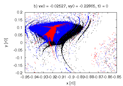
First we demonstrate the effect of the Sun’s gravitational perturbation on the size and position of the domain containing non-escaping trajectories for days ( ), see Fig. 2. Panel (a) depicts the (ICM) () for RTBP in region Initial velocities for all trajectories equal to the Keplerian velocity of the point, see Table 1. As is expected from classical celestial mechanics, the triangular Lagrangian point (white cross) is situated deep inside the area of long-lived trajectories. The filamentary structure around the extended region indicates the chaotic motion of escaping particles.
Fig. 2 (b) shows the ICM for different solar masses (). Black dots represent e.g. RTBP, blue dots and red dots Two well-seen consequences can be observed due to the presence of the Sun. Firstly, the size of the domain of non-escaping trajectories diminishes in case of the larger Sun’s mass. Secondly, the position of this area is shifted outward from Earth. As a consequence of this drift, the location of the point relative to the stable island moves toward its border and beyond. We note that the position of the equilibrium point in the RFBP is situated at a different position as in the RTBP (Gabern & Jorba 2001). Considering this fact, it is worth monitoring the fate of the particle starting from the point () and its neighbourhood.

3.2 The Effect of the Integration Time
In this section the size of the long-lived island is investigated for different integration times. That is, we are interested in the number (and also the position) of non-escaped trajectories, while the criterion for escape () remains the same. The mass of the Sun is set to be In order to perform this calculation we place particles around the point,


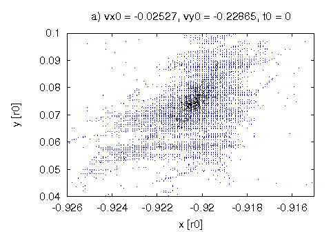
The initial points of non-escaped trajectories for different integration times ( days), are depicted by black, red and blue points, respectively in Fig. 3 (a). The longer the integration time the smaller the survival area. Consequently, we can identify a long-lived island as a subset of shorter time islands. Nevertheless, a robust filamentary structure encloses the inner compact long-lived island. Refined numerical investigations show that the filamentary structure has a self-similar nature and, therefore, one might expect chaotic behaviour in this part of the phase space.
It is known that in Hamiltonian dynamics the number of non-escaped trajectories shows an exponential decay for shorter times and follows a power-law for longer times (see for example Lai & Tél (2011)). Short time escapes are related to the transversal intersections of the stable and unstable manifolds of the UPOs where the dynamics can be considered fully hyperbolic. Particles with longer life time are confined to that region of phase space where the manifolds intersect tangentially. This phenomenon appears, in fact, close to the border of regular tori and is known as stickiness. The crossover from exponential to power law decay can indeed be seen in Fig. 3 (b).
Fig. 3 (b) shows the two segments. The straight line in the inset on semi-logarithmic scale indicates the exponential decay (), while the linear fit provides for escape rate One can estimate (Altmann, Portela & Tél 2013) the average lifetime of chaos () from the escape rate, days. The exponent in algebraic decay () is found to be which is somewhat smaller than the actual accepted, probably universal, value () of chaotic transport near the remnants of the last KAM torus (Meiss 2015).
To find analytically, and also numerically, the unstable periodic orbits and their manifolds in high dimensional phase space is a challenging task. The motion in a dimensional phase space ( is the number of degrees of freedom) proceeds on a dimensional surface where is the number of existing first integrals. Constructing any Poincaré surface of section in dimensions, if yields a confused structure-less picture, since we see the projection of any remaining dimensions.
Considering that in our model the phase space has 12 dimensions, we are not able to construct and visualize a Poincaré surface. More precisely, any 2D section of the phase space has a fuzzy structure which actually shows the projection of all the rest components of the positions and velocities. In contrast, the above defined ICMs are suitable to visualize the escape dynamics even on Poincaré surfaces of sections. This means, the initial conditions in general belong to a well-defined configuration of the system, i.e. Moon’s and Sun’s positions and all the velocities are fixed. Therefore, the escape dynamics are fully characterized by the initial coordinates and velocities of the test particle for a given energy level. Using a statistical approach by means of an ensemble, the initial positions in configuration plane depict the filamentary fractal set corresponding to the finite time chaotic motion before escape. This object can be thought as of the intersection of the plane and the stable manifold of a higher dimensional chaotic saddle. Therefore, we want to use the ICMs to apply the control to the spacecraft’s motion.
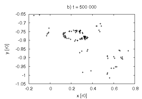
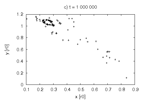
Interestingly, however, one might also find regular structures in the configuration space. Very long calculations represent that there are trajectories that form a torus in the plane, see Fig. 4. These points represent test particles orbiting the Earth at days, panel (b), and days panel (c), respectively. Higher dimensional () tori can actually be identified and characterized according to various analytical and numerical methods (Jorba 2000; Lan, Chandre & Cvitanović 2006; Laakso & Kaasalainen 2014; Lange et al. 2014). As we already mentioned above, objects in the phase space, like the torus in Fig. 4, associated to regular motions are responsible for algebraic decay of very long-lived trajectories.
3.3 The Effect of the Initial Velocity
So far in all our investigations, the test particles started with the same velocity (; ) which is equal to the velocity of the point in the circular RTBP, but it may be interesting to examine what happens to the long- lived island around the point if we change the initial velocity.
In this subsection we investigate how the structure of the ICMs changes for different initial velocities. To do this, several ICMs are generated with given conditions. With this procedure one can scan the plane for different keeping constant. Fig. 5 shows three ICMs (=1300 days) for different velocities

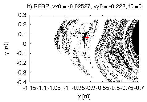
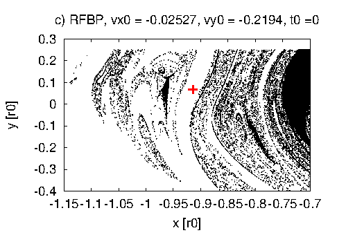
Panels (a), (b), and (c) show ICMs where initial conditions are chosen from the region including the exact position of point in the RTBP (red cross). in all three cases ( is the initial velocity component of the point) while for panel (a), (b), and (c), respectively. Different initial velocities correspond to smaller, equal, and larger values than that of the point’s One can clearly see that, depending on the initial velocity, the relative position of the long-lived island compared to the red cross changes. The smaller the , the further the long-lived island from the origin.
We can point out that small changes in results an outward/inward drift of the structures in plane. This fact will be the base of our control method, as we shall see later.
3.4 How to Keep a Spacecraft in a Confined Region
In this section we present our strategy on how to keep a test particle in the system, i.e. preventing the scenario in which exceeds 1.5. Though the orbit is well-defined by the initial conditions, our method does not allow a strict station keeping, but a rather cheap control of the motion that allows for a bounded orbit around the initial one.
The basic idea of the method is to construct ICMs for appropriate initial velocities similar to that what we have seen in Fig. 5. Fig. 6 (a) shows the ICM containing test particles starting from the region with the velocity of the Lagrangian point. The RT is selected in such a way that and see Table 1 third column. These initial conditions correspond to the point in RTBP. Test integrations show that the RT leaves the system at around 500 days. Therefore, the task is to keep this trajectory in the system for an arbitrary long period of time (). The ICM is constructed as usual, where black dots represent the trajectories not leaving the system until =400 days, and the red cross shows the RT on the map.

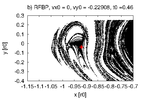
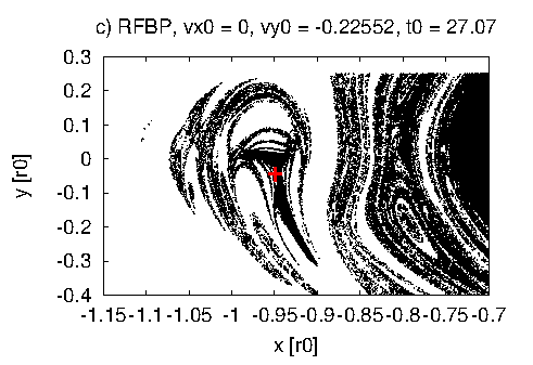
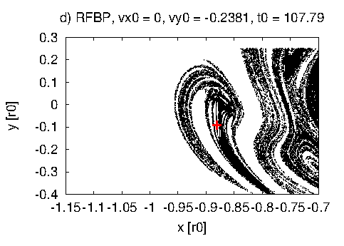
The next step is to follow the RT until the criterion is fulfilled. Then we check the actual of the RT, and depict a new ICM again for =400 days, with these velocities () as updated initial velocities, see Fig 6 (b).
Since the initial velocity of the point is very close to zero, we do not have to wait too long for the second ICM. As indicated in the above panel (b) 0.46 days were spent between the 1st and 2nd ICMs and, therefore, the structure of panel (b) is very similar to the initial one, but some distortion (shift and skew) can be observed. It can be noticed that the red cross has left the contiguous domain and is situated exactly on a nearby filament.
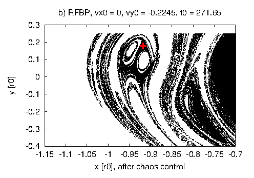
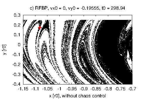
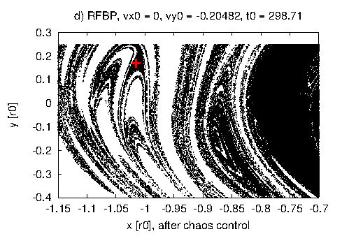
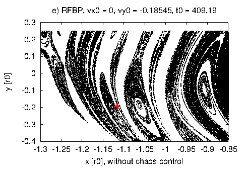
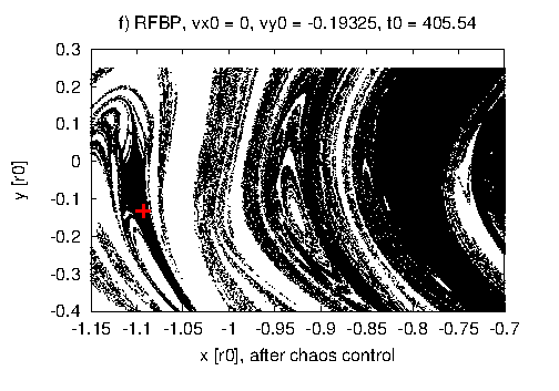
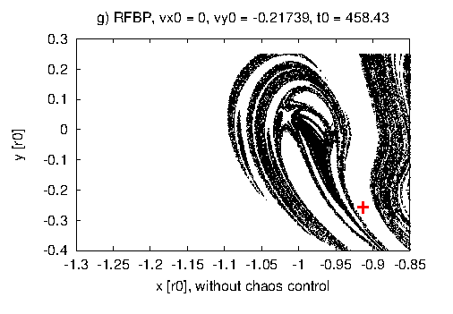
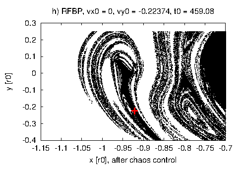
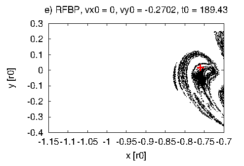
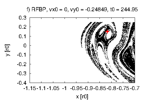
Now we repeat the procedure until the RT crosses the escape border at roughly 460 days. This will result in a series of ICMs for days with different and zero horizontal velocity. Some of these maps are shown in Figure 6. As one would expect, the consecutive ICMs follow each other with fairly constant times which related to the Moon’s orbital period, days. The corresponding epochs of various ICMs are shown above the panels.
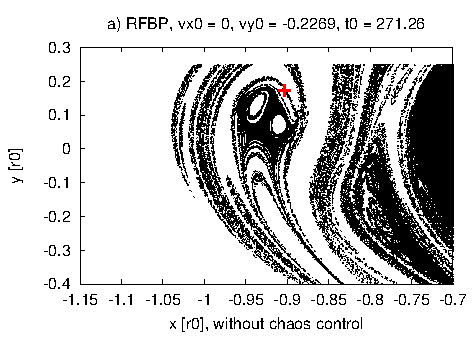
Nevertheless, there is a more robust and interesting phenomenon that can be observed if we look at carefully the different ICMs. Namely, the RT moves along the filamentary structure until its escape. At the beginning of the integration, as we have seen, the RT is on the filaments very close to the long-lived island (Fig. 6, panels (a) and (b)). Then it moves away, but still along the filaments Fig. 7 left column (panels a, c, and e). Finally the red cross lies in the white region which corresponds to an extremely fast escape, see Fig. 7 (g).
The RT escapes without any intervention after 450 days, which is on the same magnitude as the average lifetime () introduced in Section 3.3. Having constructed all the ICMs until the escape (Fig. 6 and Fig. 7 left column), we can formulate the basic objective of the control procedure. That is, the RT should be shifted from filaments to a long-lived island with the lowest possible energy consumption.
There are two essential questions arising: 1. How to do this? 2. When to do this?
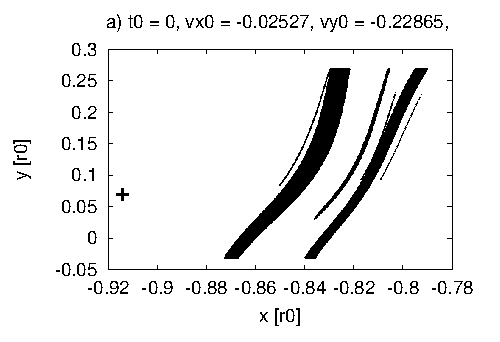
We start with the answer to the second question. Obviously, the control must start before the RT leaves the filamentary structure. A good indicator of this is the average lifetime of chaotic behaviour, 200 days. Let us consider the ICM corresponding to instance 244.95, which is the 10th ICM after =0, Fig. 6 (f). We might want to start the control at this time and see whether the red cross lands in the long-lived island in the next ICM, at 271.26 days (Fig. 7 a).
At this point we should address the answer to the first question. Since we know the system dynamics only at discrete times, at every single ICM, a natural choice is a continuous tangential force acting on the RT (or spacecraft/satellite) between two ICMs in the following form,
| (1) |
where and are the magnitude of the applied force in directions and (where is the component, is the component of the velocity vector), is the instance when the control begins and describes the length of the control.
In general, we switch on the propulsion at (or equivalently when we reach the criterion 0 and 0) in order to manoeuvre the spacecraft to a given phase space position, Therefore, we should have an approximate initial guess for the magnitude of the force (thrust or breaking). The energy conservation between two consecutive ICMs can serve a valuable choice for the force we need. (See the Appendix A for details.)
However, there is a problem if we adjust the velocity of the satellite. Namely, the next ICM in the row will be at a different time with a slightly different structure than it should be without control.
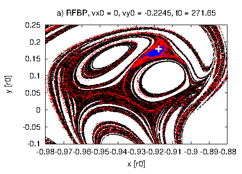
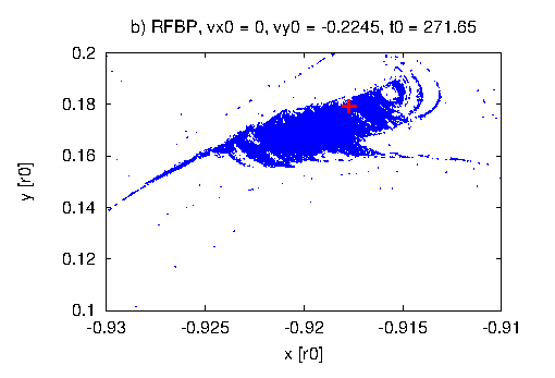
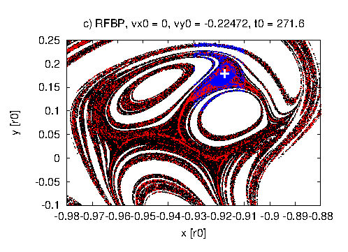
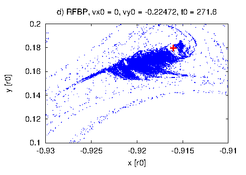
Let us consider a particular exercise to provide a better insight into the control. Fig. 6 and the left column of Fig. 7 (panels a,c,e, and g) show what happens if no control is used. In brief, the red cross leaves the pre-defined (¡1.5) region after 450 days. As we know from previous simulations, the average lifetime of the chaotic behaviour before escape is roughly 200 days. So, we should try to apply the control procedure around this time. For instance, we can choose the 10th ICM at 244.95 (Fig. 6 f) to start the procedure, and then we want to reach the long-lived island appearing on the next ICM, 11th in the row at 271.26, Fig. 7(a). However, as discussed earlier, this ICM will have a different structure at different time (271.65), due to the intervention applied between two maps, compare Fig. 7 (a) and (b). Equation (2) provides an approximate value to the tangential force that should be used for the control, N. This force is valid in cases the satellite has a mass of 1 kg. This operation is performed between and for 26.9 days, see Eq. (1). The sign of the force, i.e. thrusting or pushing back, can be obtained from the relative position of the RT and the long-lived island. For example, if we want to push the RT (red cross in Fig. 7(a)) slightly outside, then we need a push back force. The smaller the velocity, the larger the distance to the central object. Table 2 summarizes the result of the control procedure. The first row contains the coordinates of the RT, belonging to the 10th ICM section point and time. The second row shows the coordinates of the RT at the next, the 11th section point without chaos control. In the third row we can see the coordinates of the RT at the 11th section point after chaos control between the 10th and the 11th section points.
| time of the ICM [day] | |||||
|---|---|---|---|---|---|
| -0.81724699846 | 0 | 0.15185082461 | -0.24849685052 | 244.95 (before control, Fig. 6 (f)) | |
| -0.90315303819 | 0 | 0.17493609008 | -0.22690346315 | 271.26 (without control, Fig. 7 (a)) | |
| -0.91770366237 | 0 | 0.18092762375 | -0.22450011830 | 271.65 (after control, Fig. 7 (b)) |
In fact, the approximation of the control force does not guarantee that we can reach the selected domain of the phase space. In this situation a successive iteration is needed to drive the trajectory precisely to the appropriate place. In our case, a factor of 2 is needed to have a perfect force, N. If the manoeuvre is successful (e.g. Fig. 7 b), which means the RT pinpointed the desired long-lived island, we can be sure that the trajectory will not escape, at least during the next 400 days, i.e. it remains in the black long-lived region, see the right column of Fig. 7, panels( b), (d), (f) and (h). And if, after a while, it leaves that domain along a filament, just a simple repetition of the above control procedure is needed to keep the particle in the system at least for time.
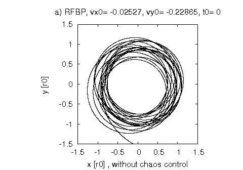
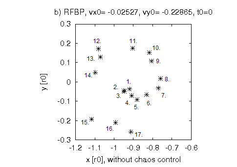
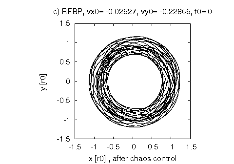
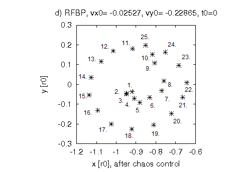
Fig. 8 depicts the result of the control considering the RT. The first row illustrates the uncontrolled motion with an escape after several revolutions in the plane. While the second row shows the motion after the control, we refer to Fig. 7 (a) and (b) and Table 2. We also note that Fig. 8 (b) and (d) correspond to a section of the phase space defined by conditions =0 and 0 similarly to ICMs but show all the consecutive section points of RT (marked by numbers). It is clearly seen that after the intervention, the section points are aligned around a ”smooth” spiral indicating that the motion becomes regular in some sense.
However, as we have already seen in Fig. 2, there are subsets of a certain ICM corresponding to longer lifetimes. That is, if we know the position of such a sub-region, the control force can be fine tuned in order to land in this smaller but long-lived island. To visualize this we present two ICMs for =400, 1300, and 13000 days at slightly different epochs, see Fig. 9. The first row shows the ICM with the force ( N) that we used during the control process. This results in a trajectory bounded for more than 36000 days, Fig. 8 (a) and (b). Fig. 9 (b) indicates that the RT lies in the domain of longer life time. In contrast, using a somewhat smaller force , N, we reach the ICM 0.05 days earlier, at t=271.6 days. In this map (Fig. 9 d) the destination of the RT is outside the blue region, consequently, the RT leaves the system earlier.
In addition, we found that the energy consumption in case of a spacecraft with a mass of 1 kg is 11.3 kJ, while in a more realistic case, say, the SOHO satellite, which has a mass 1850kg, 20.9 MJ.
3.5 Transfer from Low Earth Orbit (LEO) to Low Lunar Orbit (LLO) through the Point
In the following we show a transfer from low Earth orbit (LEO: 189 km circular orbit above the ground) to a circular low Lunar orbit (LLO: 106 km above the Moon’s surface) through the point’s long-lived island.
In this subsection we demonstrate how to use the above mentioned chaos control method for low energy interplanetary transfers between Earth and the Moon. If the dynamics are regular, i.e a two-body approach is valid, large corrections cannot be achieved by small parameter changes and, therefore, no significant energy savings can be made compared to the classical methods (Hohmann transfer, weak stability boundary method). In other words, the method works only in the chaotic phase space regime, (far from the Earth and Moon) where unstable dynamics govern the motion under the gravitational influence of both objects.
Therefore, one needs to reach that domain of phase space where unstable dynamics dominates, and control can be easily realized. A good place to do this is the theoretical position of the Lagrangian point of the Earth-Moon-satellite RTB system. As shown before, the point is not stable anymore if the Sun’s perturbation is taken into account but (arbitrarily) long-lived islands can be found that are suitable for control and temporal parking the space craft at the Moon’s orbit. Moreover, several initial conditions near the point lead to a Moon crashing orbit as we will see later in Fig. 11.
We suppose an ion propulsion thrust. That is, a continuous acting low fuel-cost manoeuvre instead of an impulse like force. Our calculations are compared to the widely used weak stability boundary (WSB) method published by Belbruno & Miller (1993). Similar to the WSB method we focus only on the transfer between LEO and LLO and ignore the energy cost of launch from the Earth basis and the breaking at vicinity of the Moon.
The first stage of our transfer consists of the orbit from LEO to a long-lived island around the point, similar to the ballistic capture method (Salazar, Macau & Winter 2014). Due to the appropriate continuous thrust (), the spacecraft will spiral out from LEO until reaching the escape velocity and leaving the Earth’s range in an elongated elliptical orbit which has a turning point (apogeum) at the Moon’s orbit, Figure 10. This part of the manoeuvre is similar to the Hohmann transfer, with a difference that the spacecraft arrives at the Moon’s orbit exactly at the point, instead at the Moon itself. This fact allows us either to keep the satellite in the long-lived island with the above mentioned chaos control method or to eject it directly to the Moon after a while.
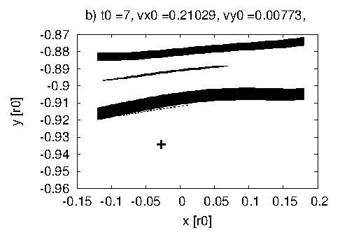
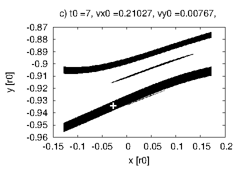
This can later be done by a small control force which enables finding the initial conditions that lead to an LLO. Figure 11 shows the initial condition map in the vicinity of , similar to Fig. 2. The cross shows the reference trajectory after the first manoeuvre, while the stripes denote the desired (x,y) co-ordinates in order to get LLO. Using a breaking force for days, the reference trajectory can be pushed into the bottom stripe (Figure 11c), and after 29.54 days it will reach the LLO. In detail, by fine tuning the thrust we can get a reference trajectory that approaches the Moon at 106 km (cross in Fig. 11). The required energy is 58.38 kJ for a 1 kg space craft, which corresponds to V = 0.0156 km/s. This intervention is the second control manoeuvre in Fig 10. After this control we need 29.54 days to reach the LLO.
Table 3 gives the summary of the controls applied during the entire mission. The energy consumption of the first manoeuvre, from the LEO to the -long-lived island, is 29.31 MJ. This amount of energy is equals to that of the Hohmann transfer cost of 29.32 MJoule ( = 3.132 km/s).
Manoeuvre 2 from -orbit to the low Lunar orbit needs a velocity adjustment of = 0.6933 km/s (0.058MJ, see above). Comparing this result to the data of Table 3 (mnv. 2) in Belbruno & Miller (1993), we find that this is only slightly less than the desired 0.695 km/s in weak stability boundary method, but the time of flight is much less, 1 month instead of 3-5 months (Belbruno & Miller 1993).
Manouevre 3 is the velocity reduction to the circular Lunar orbit at an altitude of 106 km above the Moon’s surface. Table 3 contains only the required since the time of intervention can be chosen arbitrarily.

| manoeuvre | [day] | t [day] | [N] | [N] | from | to | [MJ] | V [km/s] | |
|---|---|---|---|---|---|---|---|---|---|
| 1. | 0 | 8.9 | 0 | 0.0258 | LEO | orbit | 29.3 | ||
| 2. | 9.9 | 6.68 | -0.0001 | -0.0001 | orbit | to the Moon | 0.05838 | 0.0156 | |
| 3. | 29.54 | – | – | – | 106 km above the Moon | LLO | 0.6777 |
4 Summary and Conclusions
We published our first results in Slíz , Süli & Kovács (2015), where we presented our chaos control method for one special case: to keep a spacecraft (as a 1-kg test particle) near the Earth-Moon point in the presence of the Sun (RFBP). Since then we realized that this method is generalisable, and also suitable for targeting a spacecraft. In this work we presented a generally applicable method to keep a spacecraft in a confined region or targeting it, when on the ICM there is a long-lived island in the ”nearby”. The applied force is very small, tangentially, proportional to the velocity, and pushes the RT onto this island. We presented two examples: 1. how to keep a spacecraft in a pre-defined region, and 2. how to go to the Moon (from LEO to LLO). In both cases the applied force is within the range of the ion thruster. We showed the influence of the Sun’s mass, the integration time and the initial velocity to the size, shift and shape of the long-lived islands around the Earth-Moon point. Regarding the shift of point for different initial velocities, we found the same result as Schwarz & Eggl (2011) found in binary systems.
Numerical simulations show that the presence of the Sun has dramatic effects on the size and the position of bounded motion around the triangular equilibrium point . Hence, we pointed out that the question of keeping a particle in the system is relevant, even if we start the RT very close to the long-lived island near the Lagrangian point , which is thought to be linearly stable in the restricted three body problem.
Using the methodology of transient chaos, we can show that the filamentary structure of ICMs are related to the stable manifold of the so called chaotic saddle. Moreover, the escape dynamics are found to be a classical phenomenon of the finite time chaotic behaviour and therefore, the well-known statistical description for non-escaping trajectories can be used. That is, for short times an exponential decay of surviving trajectories can be seen. The dynamics of this regime are governed by the fractal set obtained around the long-lived islands in ICMs. On the other hand, the number of non-escaped trajectories shows an algebraic decay for longer times, which is a consequence of the stickiness effect around the KAM tori embedded in the phase space.
We have used a combination of two chaos control methods in order to have a suitable method of avoiding the escape of a test particle. The results show that, interestingly, the RT leaves the system along the filamentary structure constructed at different times and at different () velocities. Taking advantage of this phenomenon, the essence of our control mechanism is pushing the RT back into a long-lived island whose future position is known from numerical integration.
Since we know the future dynamics of the satellite, this means, the structure of the subsequent ICMs are explored, and we are able to choose different regions as a target domain, depending on the survival time. In other words, applying a slightly different force in the control process, the spacecraft can land in that part of the phase space where the surviving time is much longer than the average life time of the escape dynamics. Consequently, the next intervention can be delayed by several thousands of orbits. Changing the force and the period of the control in equation (1) can serve multiple options, such as wether to optimize the mission focusing either on the energy consumption or the period of planned interventions.
The initial conditions we used could seem somewhat arbitrary. We would like to note that the finite time chaotic dynamics governed by the unstable periodic orbits and their manifolds is a robust phenomenon in general. Therefore, an obvious expectation is that different initial conditions provide similar fractal structures in ICMs than in the model we used. Our preliminary results show that Keplerian initial conditions of test particles led to a qualitatively similar filamentary structure in phase space.
Finally, we should mention that dynamical control of a test body does not always mean its prevention from escape. There might be situations when escape is a more desirable scenario than keeping something close to the Earth or Moon. Imagine we want to hijack an asteroid using the least amount of energy possible. A natural choice would be to push it away from the filament into the white region where fast escape takes place (Fig. 6 and 7). Our simulations (not presented here) show that particles ejected from the vicinity of the Moon’s point terminated to near-Earth orbits around the Sun. Initial condition maps and chaos control method we used for our study can also be useful to model these scenarios, either in planar or in spatial Sun-Earth-Moon-asteroid systems. However, such computations are beyond the scope of recent work.
We also showed that the required energy for a transfer from LEO to LLO is about the same amount as the weak stability boundary method predicts, but the time of flight is significantly smaller.
The method described in this paper is realisable with - even solar powered - electric ion propulsion producing very low (milli-newtons) thrust. It is true that in this case, the journey requires a higher delta-v and usually there is a large increase in time compared to a chemical rocket, but the best efficiency of electrical thrusters may significantly reduce the cost of the flight. In relation to the Earth-Moon, the increased flying time is not suitable for human space flight, but the situation is quite different in the case of interplanetary flight where the difference matters less. (Brophy & Rogers 2000).
This chaos control method can be applied not only for celestial mechanics problems, but also other fields of science, and can be used even in engineering practice or biophysics, wherever behind the chaotic phenomenon there is a time dependent mathematic model. In celestial mechanics it can be applied planning the mission to Mars or to other planets and/or to find an ” interplanetary superhighway”.
Acknowledgements
This work was partially supported by the Hungarian OTKA Grant Nr. NK 100296. The authors want to thank Dr. T. Tél his valuable suggestions and helpful discussions.
References
- [1] Altmann E.G., Kantz H., 2007, EL, 78, 10008
- [2] Altmann E.G., Portela J.S.E. & Tél T., 2013, RvMP, 85, 869
- [3] Astakhov S., Burbanks A., Wiggins S. & Farrelly D., 2004, ASPC, 316, 80
- [4] Belbruno E., Space Manifold Dynamics, Springer, NY, 133-148
- [5] Belbruno E.A., 1987, AIAA’87
- [6] Belbruno E.A. & Miller J.K., 1993, JGCD, 16, 770
- [7] Belló G., Gómez G. & Masdemont J., 2010, Space Manifold Dynamics, Springer, NY, 1-96
- [8] Bennett C.L., 1996, AAS, 28, 1391
- [9] Bleher S., Grebogi C. & Ott E., 1990, PhyD, 46, 87
- [10] Boccaletti D. & Pucacco G., 2000, AdSAC, 10, 540
- [11] Brophy J. R. & Rodgers D. H., 2000, AIAA-2000-3142
- [12] Branicki M. & Wiggins S., 2010, NPGeo, 17, 1
- [13] Celletti A. & Giorgilli A., 1991, CeMDA, 50, 31
- [14] Contopoulos G., 2004, Order and Chaos in Dynamical Astronomy, Springer-Verlag, NY
- [15] Contopoulos G. & Harsoula M., 2008, IJBC, 18, 2929
- [16] Contopoulos G. & Harsoula M., 2013, MNRAS, 436, 1201
- [17] Efthymiopoulos C., 2012, SerAJ, 184, 1
- [18] Érdi B., Nagy I., Sándor Z., Süli Á. & Fröhlich G., 2007, MNRAS, 381, 33
- [19] Ernst A., Berczik P., Just A. & Noel T., 2015, AN, 336, 577
- [20] Fehlberg E., 1968, Classical fifth-, sixth-, seventh-, and eight-order Runge-Kutta formulas with stepsize control, NASA TR R-287
- [21] Fenichel N., 1979, J. Diff. Eqn., 31, 53-98
- [22] Freistetter F., 2006, A&A, 453, 353
- [23] Gabern F. & Jorba À., 2001, Discrete and Continuous Dynamical Systems – Series B, 1, 143
- [24] Gaspard P., 2005, Chaos, Scattering and Statistical Mechanics, Cambridge University Press, New York
- [25] Harsoula M., Contopoulos G. & Efthymiopoulos C., 2015, JPhA, 48, 135102
- [26] Howell K. C., Barden B. T., Wilson R S. & Lo M. W., Advances in the Astronautical Sciences 97, 1665-1684
- [27] Jorba À., 2000, A&A, 364, 327
- [28] Jung C. & Zotos E. E., 2015, PASA, 32, e042
- [29] Kevin E. Post, Belbruno E. & Topputo F., 2012, GLEX-2012.02.3.6x12248
- [30] Kovács T. & Érdi B., 2009, CeMDA, 105, 289
- [31] Laakso T.& Kaasalainen M., 2014, arXiv, arXiv:1403.0395
- [32] Lai Y.-C., 1996, Phys. Lett. A, 221, 375-383
- [33] Lai Y. & Tél T. 2011, Transient Chaos, Springer, NY
- [34] Lan Y., Chandre C. & Cvitanović P., 2006, PhRvE, 74, 046206
- [35] Lange S., Richter M., Onken F., Bäcker A. & Ketzmerick R., 2014, Chaos, 24, 024409
- [36] Lichtenberg A. J. & Liebermann M. A.,1983, Regular and Chaotic Dynamics, Springer, NY
- [37] Lissauer J.J. & Chambers J.E., 2008, Icar, 195, 16
- [38] Maffione N. P., Gómez F. A., Cincotta P. M., Giordano C. M., Cooper A. P. & O’Shea B. W., 2015, MNRAS, 453, 2830
- [39] Meiss J. D., 2015, Chaos, 25, 097602
- [40] Moser J., 1958, AJ, 63, 439
- [41] Ott E., 1993, Chaos in Dynamical Systems, Cambridge University Press, New York
- [42] Ott E., Grebogi C. & Yorke J.A., 1990, PhRvL, 64, 1196
- [43] P Páez R.I. & Efthymiopoulos C., 2015, CeMDA, 121, 139
- [44] Rosa F., Miniscalco R., Rame F. & Torchia F., 2005, ESASP, 602, 37
- [45] Salazar F.J.T., Macau E.E.N. & Winter O.C., 2014, AdSpR, 53, 543
- [46] Schwarz, R., & Eggl, S., 2011, Publications of the Astronomy Department of the Eotvos Lorand University, 20, 135
- [47] Schwarz R., Süli Á., Dvorak R. & Pilat-Lohinger E., 2009, CeMDA, 104, 69
- [48] Simó C., Stuchi T. J., 2000, PhyD, 140, 1
- [49] Slíz J., Süli Á. & Kovács T., 2015, AN, 336, 23
- [50] Tél T. & Gruiz M., 2006, Chaotic Dybamics, Cambridge University Press
- [51] Tél T.& Lai Y.-C., 2008, PhR, 460, 245
- [52] Utku A., Hagen L. & Palmer P., 2015, CeMDA, 123, 387
Appendix A Estimation of the control force
Figure 6 (f) and Figure 7(a) indicate that the aim of a control is to achieve a desired small displacement in order to land into that part of the ICM, where a long-lived island is situated. It is also pointed out that if we perform a tiny but long control force, the structure of the next ICM depends on the force applied itself. Therefore, an initial guess as to the magnitude of the intervention is required. To have this information, we can use a simple calculation based on the energy conservation in two-body problem.
| (2) |
where and can be obtained from the th and th ICMs, and are the mass of the satellite and the Moon, respectively, denotes the Newtonian gravitational constant. In equation (2) index indicates the velocity and position of the desired point on the ICM, while index refers to the starting point on the preceding ICM. Applying equation (2) in case of Fig. 6 (f) and Fig. 7 (a), we get the estimation the absolute value to the control force N when the satellite has the mass 1kg and assuming a circular orbit. The later means that the r.h.s. of equation (2) is where denotes the Moon’s orbital distance to the Earth while is the absolute value of the control force.