∎
55email: zhaoyq@uw.edu 66institutetext: U. Hetmaniuk 77institutetext: Department of Applied Mathematics, University of Washington, Box 353925, Seattle, WA 98195-3925, U.S.A.
Nested Dissection Solver for Transport in 3D Nano-Electronic Devices
Abstract
The Hierarchical Schur Complement method (HSC), and the HSC-extension, have significantly accelerated the evaluation of the retarded Green’s function, particularly the lesser Green’s function, for two-dimensional nanoscale devices. In this work, the HSC-extension is applied to determine the solution of non-equilibrium Green’s functions (NEGF) on three-dimensional nanoscale devices. The operation count for the HSC-extension is analyzed for a cuboid device. When a cubic device is discretized with grid points, the state-of-the-art Recursive Green Function (RGF) algorithm takes operations, whereas the HSC-extension only requires operations. Operation counts and runtimes are also studied for three-dimensional nanoscale devices of practical interest: a graphene-boron nitride-graphene multilayer system, a silicon nanowire, and a DNA molecule. The numerical experiments indicate that the cost for the HSC-extension is proportional to the solution of one linear system (or one LU-factorization) and that the runtime speed-ups over RGF exceed three orders of magnitude when simulating realistic devices, such as a graphene-boron nitride-graphene multilayer system with 40,000 atoms.
Keywords:
nanodevice numerical simulation Green’s functions 3D device modeling1 Introduction
With the downscaling of nanoscale electronic devices, the non-equilibrium Green’s function (NEGF) method has become the most effective and accurate modeling approach in predicting the electronic transport performance. The self-consistent solution of NEGF and Poisson’s equations is capable of accurately modeling coherent as well as decoherent transport by integrating atomic/molecular orbital level physics datta2002non . An aspect of NEGF, that currently prevents a broader use, is the large computational cost associated with the method.
Researchers and analysts have used several approximations to alleviate this cost. Examples include the mode-space approximation ren2003nanomos , which couples 1D NEGF transport simulation to transverse states from solving 2D Schrödinger equation on the cross-section, and the restriction to levels of lower accuracy (such as tight-binding or effective mass levels). Although these approximations of NEGF have successfully predicted the transport characteristics of nanoscale devices barker1989theory ; luisier2006quantum , these alternatives remain unable to capture atomic-scale inhomogeneities, such as surface roughness, unintentional doping, and trapped charges (see, for example, asenov2003simulation for an illustration of the resulting inaccuracy). The modeling of such inhomogeneities requires a full 3D real-space NEGF simulation. Recent studies martinez2007study ; martinez2006development ; martinez2007self ; martinez2009comparison ; martinez2010detailed have performed 3D NEGF simulations to handle these inhomogeneities but with “coarse discretization” (i.e. small number of atomic orbitals or small number of grid points) to control the computational cost. To enhance the predictability of these 3D NEGF simulations, finer discretizations have to be considered. Therefore the computational cost of NEGF needs to be addressed. The goal of this paper is to present a numerical method that significantly reduces the cost of 3D NEGF simulations.
During a NEGF simulation, the main computational bottleneck is the repeated evaluations of the retarded Green’s function, , and the lesser Green’s function, , over a wide range of energy values Anantram2008aa . Physical quantities, such as density of states, carrier density, and transmission coefficients, are obtained from the evaluations of these Green’s functions. After discretization of the nanoscale device, these repeated evaluations amount to computing entries in the matrices and that approximate, respectively, the retarded and lesser Green’s functions. Recall that the matrix is defined as
| (1) |
where is the system Hamiltonian matrix and is the identity matrix. The self-energy matrix consists of two parts: the contact self-energy and a self-energy to represent scattering mechanisms . The matrix is defined as
| (2) |
where corresponds to the lesser self-energy matrix Anantram2008aa . To compute diagonal and desired off-diagonal entries of and , the recursive Green’s function algorithm (RGF) Svizhenko2002aa has been the algorithm of choice for many years. Recently, the hierarchical Schur complement (HSC) method Lin2009ab ; Lin2011ac and the fast inverse using nested dissection (FIND) method Li2008ab ; Li2011ab have exhibited significant speed-ups over RGF to evaluate the diagonal entries of . Both of these methods have a smaller operation count than the RGF method. Our HSC-extension to compute diagonal and desired off-diagonal entries of hetmaniuk2013nested has also demonstrated significant speed-ups over RGF simulations for 2D nanoscale devices. In this paper, the efficiency of the HSC-extension hetmaniuk2013nested over the RGF method is studied for 3D nanoscale devices.
The rest of the paper is organized as follows. Section 2 gives a brief description of the RGF and HSC-extension approaches and discusses the asymptotic operation counts for both approaches when simulating 3D devices. Section 3 presents the runtime analysis for a cuboid structure with a regular mesh and three state-of-the-art nanoscale devices: a graphene-boron nitride device with a multilayer hexagonal mesh; a silicon nanowire structure with 10 localized atomic orbitals; and a DNA molecule sequence with an unstructured atomic connectivity. Section 4 provides a brief summary of the numerical experiments.
2 Algorithms overview and cost analysis
This section briefly describes the RGF method Svizhenko2002aa and the HSC-extension approach hetmaniuk2013nested . Then the operation counts for both methods are discussed when simulating cuboid or brick-like nanoscale devices.
2.1 Overview of the RGF algorithm
The RGF algorithm Svizhenko2002aa evaluates the specific entries of the matrices and when the system matrix is structured as a block-tridiagonal matrix. The off-diagonal and diagonal blocks of are uniquely associated with layers (of atoms or of grid points) orthogonal to the transport direction, usually the -direction. The RGF algorithm is composed of two passes to compute diagonal entries of and two passes to compute diagonal and desired off-diagonal entries of . The two passes to compute entries of (or of ) are interpreted as follows:
-
•
the first pass marches one layer at a time from left to right along the -direction and, recursively, folds the effect of left layers into the current layer;
-
•
the second pass marches one layer at a time from right to left along the -direction and, recursively, extracts the diagonal blocks and the nearest neighbor off-diagonal blocks for the final result.
Mathematically, when computing diagonal entries of , the first pass amounts to transforming into a block diagonal matrix ,
| (3) |
where is a lower block-triangular matrix with identity blocks on the diagonal. Recall that being a complex symmetric matrix, the block -factorization is a particular form of a block LU-factorization. The second pass in the evaluation of entries for is expressed by the formula
| (4) |
(see Takahashi1973 ; Erisman1975 for further details). Starting from the knowledge of the block on the diagonal of for the rightmost layer111The block on the diagonal of for the rightmost layer is the corresponding block in the matrix ., the formula (4) provides, one layer at a time, the diagonal block and the nearest neighbor off-diagonal blocks when marching from right to left along the -direction.
When computing , the first pass amounts to evaluating the matrix-matrix products,
| (5) |
where the matrices and form the block -factorization of . The second pass in the evaluation of entries for is expressed by the formula
| (6) |
(see Takahashi1973 for further details). Starting from the knowledge of the block on the diagonal of for the rightmost layer, the formula (6) provides, one layer at a time, the diagonal block and the nearest neighbor off-diagonal blocks when marching from right to left along the -direction.
2.2 Overview of the HSC algorithm and its extension for
The HSC method and its extension Lin2009ab ; Lin2011ac ; hetmaniuk2013nested evaluate specific entries of the matrices and when the matrix is symmetric and sparse. In contrast to RGF, the matrix is not required to be block-tridiagonal.
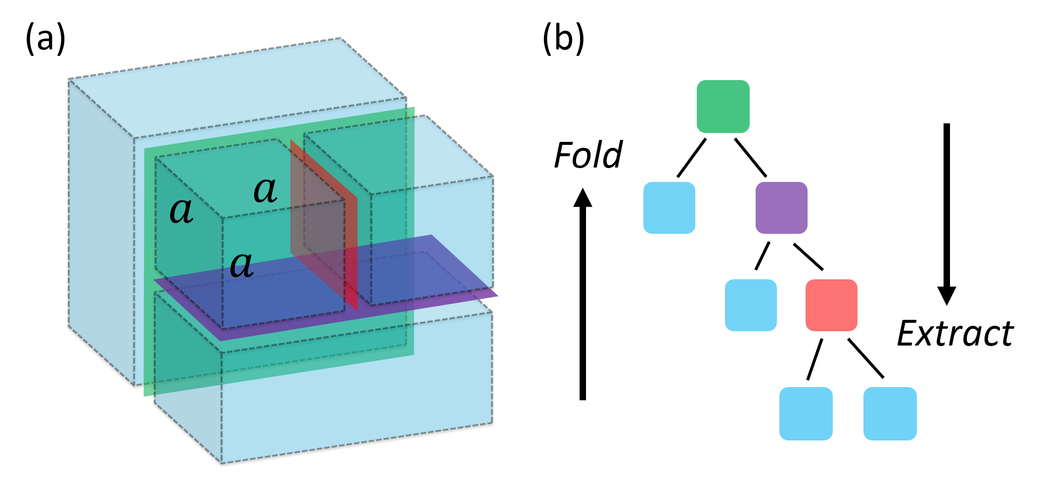
The first step of the HSC method and of its extension gathers the grid points (or atoms) into arbitrarily-shaped clusters. These clusters are then organized in a binary tree. The ordering of rows of according to this hierarchy of clusters arranges the non-entries of into a block arrow-shaped structure. Such choice of ordering allows to fold and to extract in any physical direction when following the vertical hierarchy of the binary tree.
Fig. 1 illustrates a partition for a cuboid device of size and the corresponding binary tree222In practice, the binary tree is likely to be balanced.. Three levels of separators are depicted in Fig. 1 and the colors in the binary tree match the colors in the partition. Note that the three separators are orthogonal to three distinct physical directions. The fold process represents the computation from the lowest level to the top-most level, while the extract process marches one level at a time from the top-most level to the lowest one.
The mathematical interpretation of the two passes for remains unchanged with the stipulation that the rows of , , and are ordered according to the hierarchy of clusters in the binary tree. The first pass for is interpreted as the evaluation of the matrix-matrix products,
| (7) |
and the second pass is expressed by the formula
| (8) |
where the matrix rows remain ordered according to the hierarchy of clusters in the binary tree.
Next we provide two pseudo-codes describing, respectively, the HSC method and its extension. On the basis of the hierarchical structure of a binary tree with levels, let denote the set of all cluster indices such that cluster is an ancestor of cluster . Similarly, let denote the set of all cluster indices such that cluster is an descendant of cluster . Algorithm 1 describes the computation of specific entries of (HSC method).
Algorithm 1 (HSC: computation of )
for to do
for all the clusters on level do
for all in
for all and in
for all and in
and for all in
end for
end for
is block diagonal
for to do
for all the clusters on level do
for all cluster indices in
for all cluster indices in
end for
end for
Computed entries in match corresponding entries in
Algorithm 2 describes the computation of specific entries of with the HSC-extension. For further details about the HSC method for and about its extension for , the reader is referred to the references Lin2009ab ; Lin2011ac ; hetmaniuk2013nested .
Algorithm 2 (HSC-extension: computation of )
block diagonal
for to do
for all the clusters on level do
for all and in
end for
end for
for to do
for all the clusters on level do
for all cluster indices in
for all cluster indices in
end for
end for
Computed entries in match corresponding entries in
The key element controlling the efficiency of the HSC method and its extension is the definition of clusters in the binary tree. When the binary tree is replaced by a degenerate (or pathological) tree where each parent node has only one associated child node, the HSC method becomes equivalent to the RGF method (see, for example, (hetmaniuk2013nested, , p. 596)). For the HSC algorithm and its extension, the multilevel nested dissection defines the binary tree and the resulting clusters. The nested dissection George1973aa approach divides the domain of grid points or atoms into two uncoupled sub-domains (clusters of grid points/atoms) with a separator, such that the two disconnected sub-domains are of roughly the same size and the separator is minimized. Multilevel nested dissection repeats this division on each sub-domain, reducing the clusters down to a size small enough (manageable for an inversion of the corresponding block matrix), or until the clusters cannot be divided by nested dissection. In practice, the METIS graph partition library Karypis:1998:FHQ:305219.305248 provides the implementation of the multilevel nested dissection. This well-established partition library allows the HSC extension approach to handle any arbitrarily-discretized nanoscale electronic devices.
2.3 Operation count analysis when simulating 3D brick-like devices
Next we discuss the operation counts for the RGF method and for the HSC-extension. Consider a cuboid device, covered by a three-dimensional orthogonal mesh with , , and grid points per direction. The discretization of the Hamiltonian is obtained via a 7-point stencil. The self-energy matrix is assumed to be represented via a similar 7-point stencil (for example, with a crude diagonal approximation or with a PML-like approximation nissen2011optimized ). The resulting matrix is of dimension , where the -direction is the transport direction.
The RGF approach groups the grid points into disjoint layers, each layer holding grid points. Fig. 2 illustrates these layers for , , and .
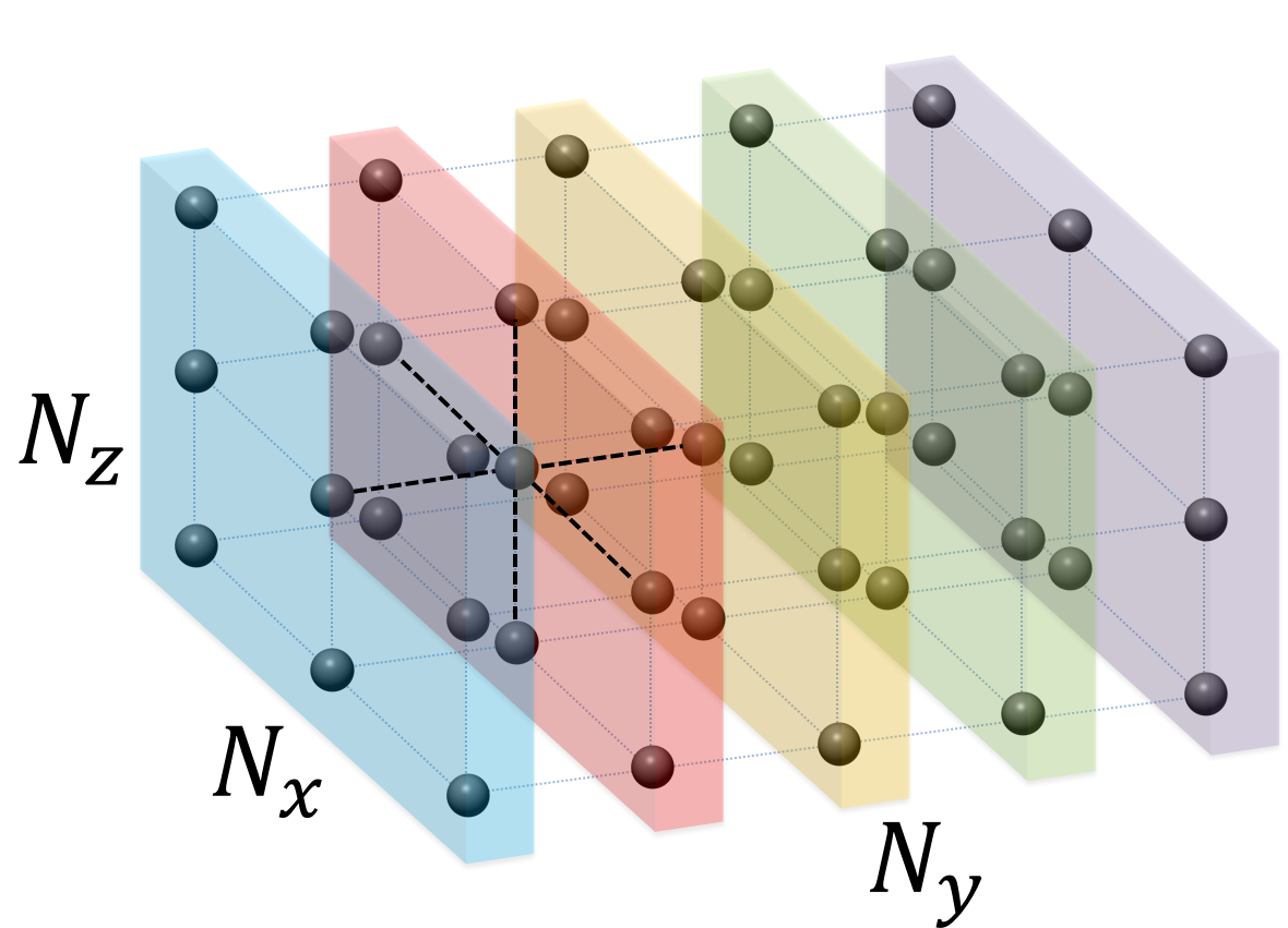
By ordering the grid points one layer at a time, the matrix exhibits the block-tridiagonal structure, required by the RGF approach. The operation count for the RGF method on this cuboid device is .
The HSC-extension employs a multilevel nested dissection to gather the grid points into a hierarchy of clusters. Fig. 3 illustrates the separators obtained at each level and the eight subdomains. The resulting binary tree is also depicted in Fig. 3 with matching colors for the separators.
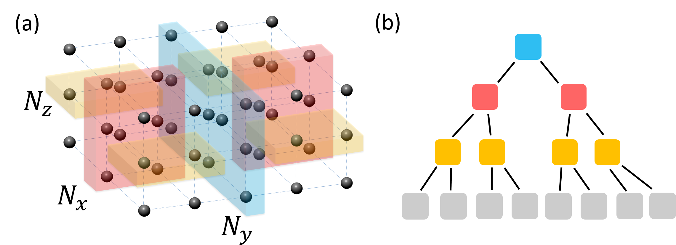
The operation count for the HSC-extension is derived in the appendix. For the sake of conciseness, the final value is summarized in Table 1.
| Configuration | HSC-extension | RGF |
|---|---|---|
| Cubic mesh () | ||
| Elongated mesh () | ||
| Flattened mesh () |
Remark
When , the operation counts for RGF and HSC reduce to their expression for 2D devices (with mesh ). Namely, for RGF, the operation count becomes and, for HSC, .
In practice the self-energy matrix contains dense blocks for the grid points on open boundary conditions. The analysis in the appendix and the counts (Table 1) do not cover such cases. The next section will study numerically the operation counts for practical nanoscale devices with open boundary conditions.
3 Numerical experiments
Next we demonstrate and analyze numerically the performance of HSC-extension approach when evaluating entries of the matrices and . First a cuboid device is used to illustrate the cost analysis presented in Section 2.3. The impact of dense blocks in when modeling open boundary conditions is also discussed. Then three nanoscale devices of practical importance are considered: a graphene-boron nitride-graphene multilayer system, a silicon nanowire (SiNW), and a DNA molecule. The discretizations for these three devices yield matrices with different sparsity pattern and provide different challenges for the HSC-extension.
Both algorithms (RGF and HSC-extension) are implemented as C codes. All the runtime data corresponds to the total CPU time for the evaluation of the diagonal and desired off-diagonal entries of and at a single energy point. For reference, timings for the LU-factorization (lu routine in MATLAB 2011b matlab calling UMFPACK v5.0.4 umfpack ) of are also included. The operation count for the LU-factorization represents the optimal cost complexity because every solution of a linear system with requires, at least, the cost of one LU-factorization. All numerical experiments are performed with one thread on a machine with Intel i7-2600 3.40GHz CPU and 12GB memory.
3.1 Cuboid nanoscale device
As described in section 2.3, a cuboid nanoscale device is considered where the Hamiltonian is constructed by effective-mass approximation and with 7-point stencil finite difference. A three-dimensional orthogonal mesh is used with , , and grid points per direction. Two distinct treatments for the self-energy matrices are studied: a diagonal approximation, referred to as SPARSE, and a DENSE approximation for modeling open boundary conditions.
3.1.1 Results with SPARSE self-energy matrices
Here diagonal self-energy matrices are considered. The matrix has the same sparsity as the Hamiltonian matrix . Fig. 4 illustrates the pattern of non-zero entries in the matrix , when the grid points are ordered one layer at a time (as in Fig. 2).
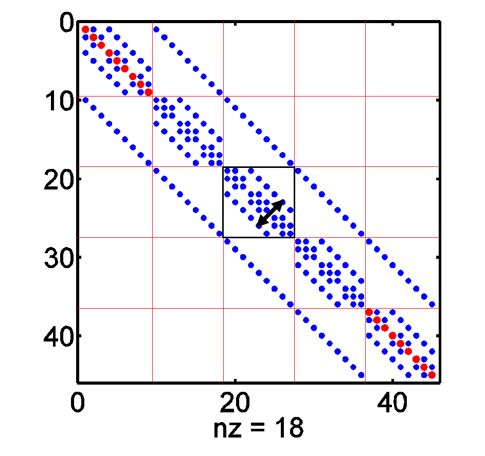
First, when , the CPU times for evaluating and at one energy point are plotted as a function of in Fig. 5.

The slopes are consistent with the analysis of section 2.3, namely for RGF and for HSC-extension. The LU-factorization of exhibits also a complexity . When , the HSC-extension exhibits a speed-up of 10 times. Note that, on this 12GB machine, RGF can solve problems only up to (the resulting matrix is of dimension 32,768), while the HSC-extension can solve these problems up to (dimension of matrix is 64,000).
Next the case of an elongated device is considered, i.e. . Fig. 6 illustrates timings for different elongated devices with square cross-section ().

The asymptotic slopes (black dashed curves) match the analysis, namely for the HSC-extension and for RGF. Here again the HSC-extension and the LU-factorization have numerically the same complexity. When is fixed at 200, the CPU time of HSC-extension is initially higher than the one for RGF at small cross-sections and becomes smaller than the one for RGF when , eventually reaching a speed-up of 2 for the largest structure studied.
Finally, for the case of flattened devices, the CPU results are shown in Fig. 7.

When and , the costs of for HSC-extension and for RGF are observed. These asymptotic behaviors are consistent with the analysis in section 2.3 and with the conclusions for 2D devices with grid points hetmaniuk2013nested .
Our numerical experiments in Fig. 4-7 illustrate the asymptotic operation count of HSC-extension as a function of system dimensions for various cuboidal shapes. In all three cases, the HSC-extension and the LU-factorization have identical asymptotic operation counts. These numerical experiments strongly suggest that the HSC-extension reaches the ideal complexity for 3D nanoscale devices.
3.1.2 Effect of DENSE self-energy matrices
Next dense self-energy matrices are considered to model open boundary conditions. Fig. 8 illustrates the pattern of non-zero entries in the matrix , when the grid points are ordered one layer at a time (as in Fig. 2).

RGF does not exploit the sparsity present in most diagonal blocks of matrix . So using a dense self-energy matrix does not impact the performance of RGF. On the other hand, the HSC-extension aims to exploit as much as possible the sparsity of . So it is important to study the impact of a dense self-energy matrix on the HSC-extension. The analysis in section 2.3 does not handle this situation.
First consider the case where . Fig. 9 plots the CPU timings as a function of .

Here the RGF calculation stops at due to memory limitation, while the HSC-extension can solve problems up to with dense self-energy matrices. The presence of a dense self-energy matrix yields larger CPU times for the HSC-extension but the asymptotic operation count is not modified.
Fig. 10 plots the CPU timings when is modified and and remain constant. Timings for RGF, for HSC-extension with sparse self-energy matrix, for HSC-extension with dense self-energy matrix, and for the LU-factorization of are reported.

Note that in this numerical experiment, the layered-structure decomposition employed in RGF is kept along -direction (even when ). When is comparable to and , the speed-up for HSC-extension over RGF is reduced when a dense self-energy matrix is considered. As gets larger, the timings of HSC-extension with the two forms of self-energy are closer and, asymptotically, approaching the complexity .
3.2 Graphene - boron nitride - graphene multilayer system
Graphene, stacked with boron nitride insulating material, is a promising material to build next generation transistors because of its extraordinary thermal and electronic properties gastro2009 . Here a multilayer heterostructure is considered, as shown in Fig. 11.
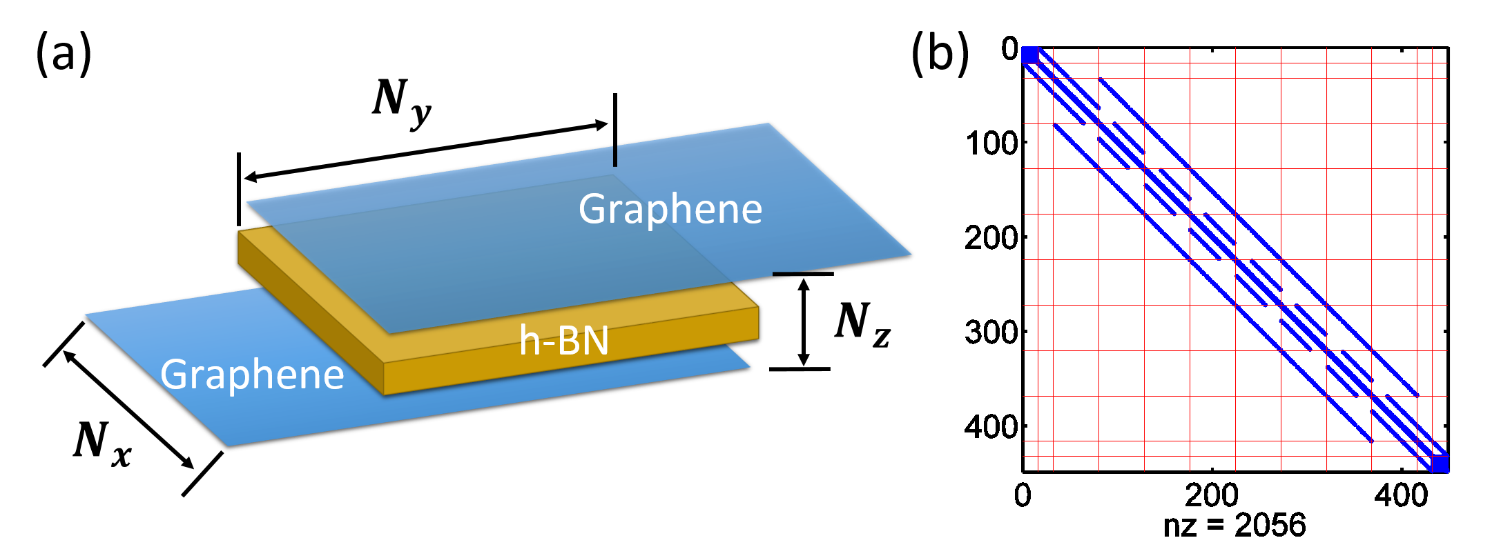
The device consists of two semi-infinitely long monolayer armchair-edged graphene nanoribbon (AGNR) electrodes sandwiching an ultra-thin hexagonal boron nitride (hBN) multilayer film, yielding a vertical tunneling heterostructure with hBN acting as a potential barrier britnell2013resonant . The hBN film is a few atomic layers thick and the central graphene-hBN-graphene (G-BN-G) overlapping heterostructure/multilayer region is stacked in AB-order (Bernal stacking). For this problem, the number of 2D vertical layers is denoted by in units of atomic layers. The system width is and the length of the multilayer stacking region is , also in units of atomic layers. The semi-infinitely long AGNR monolayer electrodes at the top and bottom layers are treated as open boundary conditions, their effect is folded into dense self-energy blocks (extreme blocks) of dimension .
The system Hamiltonian is constructed using the nearest neighbor tight binding approximation with parameters from zhao2015negative . Only the low energy orbitals are considered here; thus the Hamiltonian has the same dimension as the total number of atoms simulated. The geometric lattice complexity of the multilayer system yields an average 5-point stencil Hamiltonian sparsity (multiple hexagonal-meshed layers stacked in AB order). The complexity of RGF remains because the sparsity inside each block is not exploited. The complexity of HSC-extension is studied numerically.
Fig. 12 plots the CPU timings when and . The HSC-extension and the LU-factorization of have the same asymptote, indicating an operation count .

Fig. 13 plots the CPU timings for different configurations of , , and . The experiments illustrate that HSC-extension still exhibits a complexity similar to the LU-factorization of . For the largest devices simulated in Fig. 13(a), , the HSC-extension method offers a speed-up of 3 orders of magnitude over RGF.

The numerical experiments indicate that the asymptotic cost of HSC-extension is . This cost of HSC-extension can be compared to the cost (Table 1) for the flattened device. The term matches well with by assuming . The term is due to the Bernal stacking order for the multilayer structure in the -direction.

Finally, Fig. 14 illustrates CPU timings for an elongated device, i.e. . The timings for the HSC-extension behave like , demonstrating a lower order of complexity over the RGF method.
As a summary, the runtime cost of HSC-extension for the G-BN-G multilayer structure is
| (9) |
while the runtime cost of RGF behaves like .
3.3 Silicon nanowire structure
Silicon nanowire devices have shown promises to become key components in the next generation computer chips cui2001functional . Solving efficiently the NEGF equations for such devices is therefore important.
In order to investigate the scaling of computational runtime as a function of SiNW lateral dimensions, specifically the number of atoms in each layer and the number of unit cells, we consider a SiNW device depicted in Fig. 15(a). The number of atomic layers in -direction is denoted as and the number of silicon atoms within each atomic layer (cross-section) is denoted as . So a SiNW structure contains an array of unit cells with atoms per unit cell.
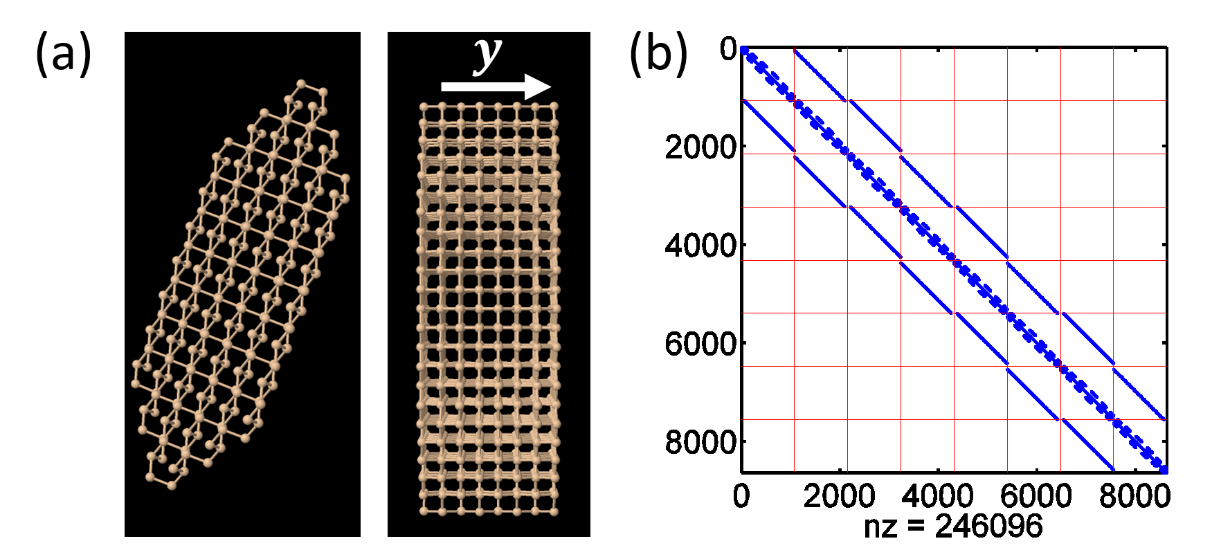
Next the tight-binding formalism luisier2006atomistic is used to discretize the system. Each silicon atom is represented by a diagonal block, thereby interconnecting with up to 40 orbitals of the nearest-neighbor silicon atoms. The resulting Hamiltonian matrix exhibits a stencil involving more than 40 points, which results in a particular computational challenge. Dense self-energy matrices of dimension are employed. Fig. 15(b) illustrates the sparsity of when and .
In this section, we consider nanowire whose length is proportional to the diameter of the cross-section, namely . When ordering the atoms one layer at a time, the Hamiltonian matrix, as well as matrix , has a block-tridiagonal structure, where each block is of dimension . The operation count for RGF becomes . Since , , and , the operation count for RGF is . The operation count for HSC-extension will be studied numerically.

Fig. 16 plots CPU timings as a function of for structures shaped by , and . Our numerical experiments exhibit an asymptotic cost of for RGF and for HSC-extension. We would like to emphasize that the complexity is valid for HSC-extension as long as , independent of the value . The HSC-extension has the same asymptotic behavior as the LU-factorization of .
In practice, analysts may consider nanowires of 20nm length. Table 2 lists CPU timings when the length is 20nm. Because these simulations did not fit in the 12GB RAM of our machine, the CPU timings were extrapolated from the asymptotes in Fig. 16.
| Shapes | HSC-extension (s) | RGF (s) | speed-up |
|---|---|---|---|
| 62.9 | 85.3 | 1.4 | |
| 1,064 | 3,030 | 2.8 | |
| 19,920 | 147,706 | 7.4 |
This extrapolation indicates that the speedup of HSC-extension over RGF improves as decreases. The reduction of enlarges the cross-section while is fixed, yielding a higher speedup of HSC-extension, which is consistent with the other experiments.
3.4 DNA molecule
Finally we test the algorithm for DNA-based structure, which represents a complex organic system. It has been shown that DNA is one of the promising candidates in the molecule devices Gohler18022011 . The study of electronic structures can be used to develop new sequencing techniques postma2010rapid , acting as DNA fingerprints. Another application is disease detection tsutsui2011electrical . Many diseases are linked with the mutation in DNA bases, resulting in different electronic properties which can be used to distinguish the mutated DNA. In our numerical experiments, the DNA molecule is described by density functional theory (DFT) method. Although the number of atoms contained in single DNA molecule is not huge, the decomposed Hamiltonian matrices are relatively dense, thus impeding an effective decomposition using the multilevel nested dissection.
The DNA molecule in our simulation is a double-helix structure containing 7 – 15 base pairs in each strand sketched in Fig. 17(a).
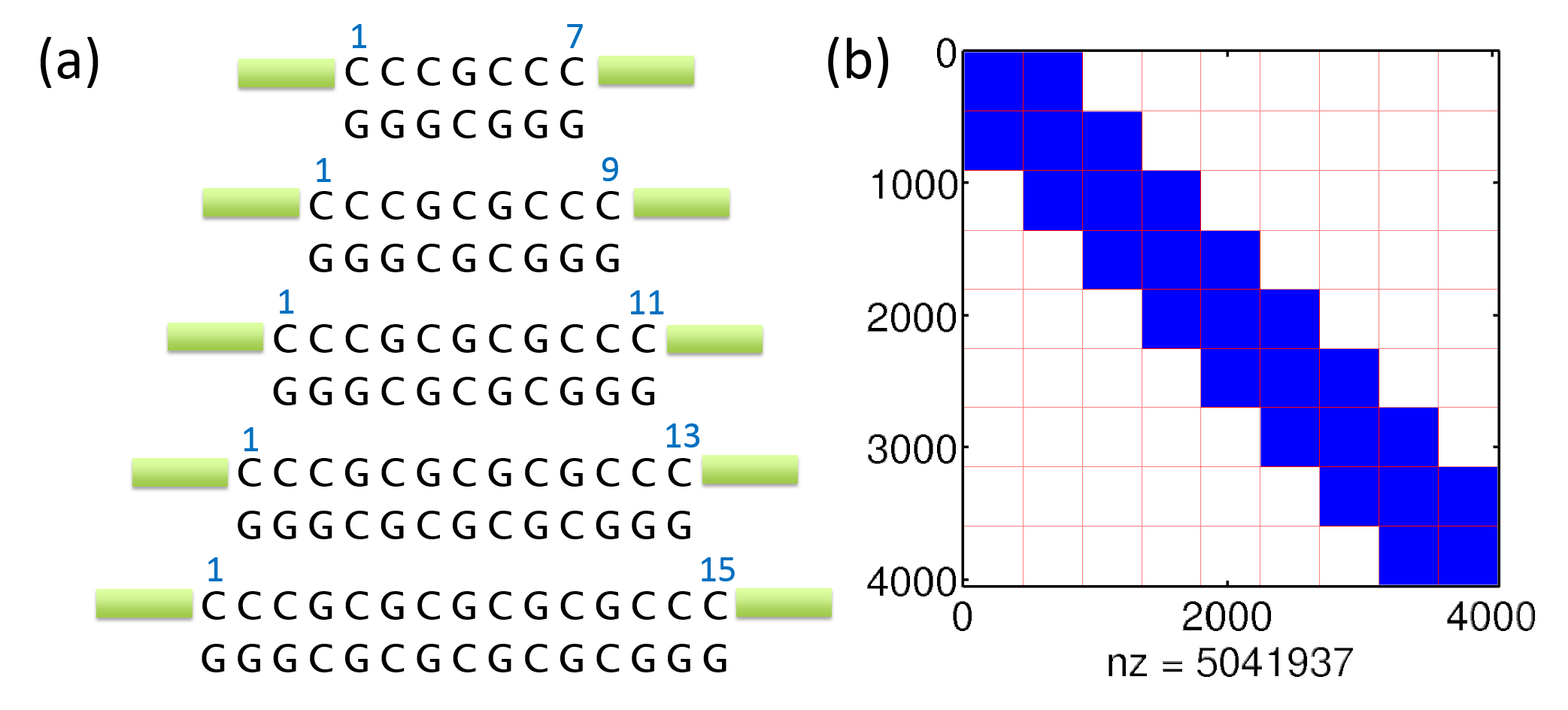
The Hamiltonian matrices are generated by DFT package GAUSSIAN 09 g09 at HG/6-31G (, ) level qi2013unified . The number of orbitals (matrix dimension) for each base is about 250. For example, for a 9-mer DNA molecule, the Hamiltonian is of dimension as shown in Fig. 17(b). The Hamiltonian can be decomposed by treating each base pair as one layer, yielding a block tri-diagonal shape with 9 layers. Different from the structures studied above, the diagonal and nearest neighbor off-diagonal blocks in the Hamiltonian are fully dense.
The CPU timing results for various DNA molecules are summarized in Table 3.
| Number of Base Pairs | 7 | 9 | 11 | 13 | 15 |
|---|---|---|---|---|---|
| HSC-extension (s) | 5.0 | 8.7 | 11.3 | 12.5 | 14.6 |
| RGF (s) | 5.5 | 7.8 | 9.7 | 11.6 | 13.7 |
For these configurations, the HSC-extension seems to be less efficient than RGF.
To better understand these CPU times, it is important to look at the clusters defined by the multilevel nested dissection. Fig. 18 illustrates the clusters used for the HSC-extension when the multilevel nested dissection is applied blindly to the graph of , and the layers used for RGF.
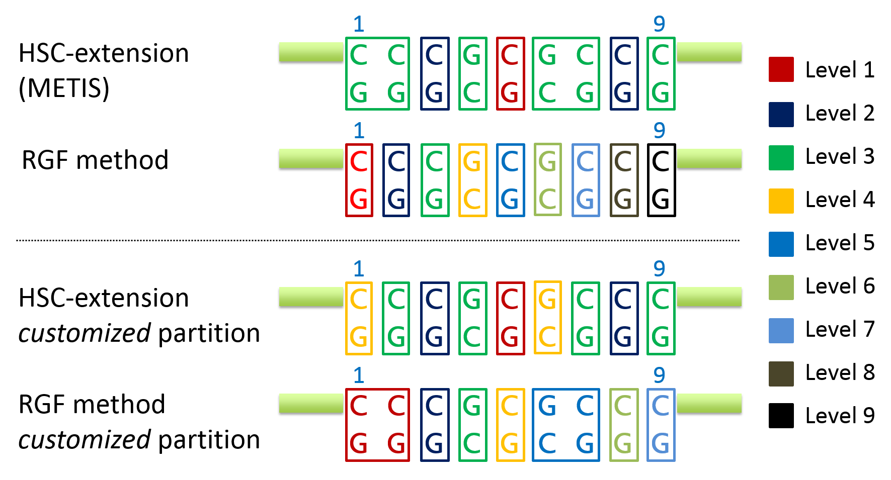
RGF employs layers with one base pair and the resulting blocks are of dimension . The multilevel nested dissection works at the level of base pairs because one base pair corresponds to one fully-dense diagonal block in the matrix . The resulting partition introduces clusters with one base pair except for two bottom level (level 3) clusters that can not be partitioned with nested dissection. These two clusters result in two block matrices of dimension . The time discrepancy arises from these two distinct choices of row gathering.
To further illustrate the impact of the row numbering or partitioning, Table 4 lists timings for two additional approaches.
| Number of Base Pairs | 9 |
|---|---|
| HSC-extension (s) | 8.7 |
| RGF (s) | 7.8 |
| HSC-extension with customized partition (s) | 7.8 |
| Customized RGF with two 2-pairs layers (s) | 11.8 |
The four different partitionings used for these approaches are depicted on Fig. 18. The customized RGF method with two 2-pairs layers gathers, twice, 2-pairs into one layer. This particular choice of layers indicates the impact of two blocks of dimension on the overall CPU time, i.e. an increase in CPU time. The customized partition for the HSC-extension allows a degenerate sub-tree333Any cluster with 2-pairs is partitioned according to a degenerate tree, where each parent node has only one child. to avoid any 2-pairs cluster. This customized partition makes the HSC-extension operate on blocks of dimension, at most, . This choice results in a lower CPU time, on par with the original RGF approach. A similar behavior was observed for other DNA molecules, where METIS gathers 2-pairs into one cluster.
These numerical experiments suggest that the HSC-extension, combined with a multilevel nested dissection, is an efficient approach even for smaller but denser matrices. When the graph partitioning is allowed to insert degenerate sub-trees, the performance is comparable with that of the performance of RGF.
4 Conclusion
In this work, we demonstrate the HSC-extension based NEGF solver as a working methodology for various 3D systems. The cost analysis for HSC-extension is performed on a cuboid structure. HSC-extension exhibits operation count of when simulating cubic device with dimension , whereas a count is observed for RGF. We also illustrate various asymptotic costs of HSC-extension when the device has an elongated shape (), when the device is flattened (), and when a dense self-energy is used to model the open boundary conditions.
The runtime performance of HSC-extension is further investigated for nano-electronic devices of practical interest: graphene-hBN-graphene multilayer heterostructure, silicon nanowire and DNA molecule. These devices exhibit distinct atomistic sparsity, indicating different computational efficiency for HSC-extension. The numerical experiments suggest that the HSC-extension exhibits asymptotic runtimes and operation counts proportional to the runtime of the LU-factorization. For all the nano-electronic devices considered, the HSC-extension becomes faster than the RGF method as the device gets larger. A 1,000 speed-up is observed for a graphene-hBN-graphene multilayer device with 40,000 atoms. Since the HSC-extension requires less operations than RGF, these speed-ups will increase as the device gets larger. A MATLAB version of HSC-extension algorithm is available at \urlhttps://els.comotion.uw.edu/express_license_technologies/glessuw.
Acknowledgements.
The authors acknowledge the support by the National Science Foundation under Grant ECCS 1231927. S. R. Patil acknowledges the support by UGC-India Grant No. F.5-50/2014(IC). M. P. Anantram and J. Qi acknowledge the support from the National Science Foundation under Grant No. 102781 for the DNA part of the paper.Appendix A Complexity Derivation of HSC-extension for 3D Cuboidal Structures
To analyze the runtime complexity of HSC-extension, we consider a cuboid device with grid points per direction.
First we discuss the case of a cubic mesh, i.e. . The operation count for evaluating diagonal entries in was discussed by Lin et al. (Lin2009ab, , section 2.5.3). According to their analysis, the operation count grows as . For the HSC-extension, the complexity for evaluating diagonal entries of is identical to the complexity for (as discussed in Hetmaniuk et al. hetmaniuk2013nested for two-dimensional devices). The overall operation count will grow as .
Next we consider the case of an elongated device, where the numbers of grid points per direction satisfy . The multilevel nested-dissection will identify subdomains, each discretized with grid points. When evaluating diagonal entries in , the operation count for each cubic subdomains will grow as . The remaining operations will involve dense matrices for the separators of dimension . The algebraic operations for one separator will include dense matrix-matrix multiplications and dense matrix inversions, yielding an asymptotic cost . The number of separators is also . The overall operation count will grow as .
Finally we consider the case of a flattened device, where the number of grid points per direction satisfy . As discussed by Lin et al. (Lin2009ab, , section 2.5.3), this configuration is similar to a two-dimensional problem with grid points. The prefactor will depend on . The HSC algorithm and our extension can proceed as if the device is two-dimensional by replacing scalar algebraic operations with block algebraic operations (each block being of dimension ). These block operations will cost . So the overall operation count will grow as .
References
- (1) S. Datta, in Electron Devices Meeting, 2002. IEDM’02. International (IEEE, 2002), pp. 703–706
- (2) Z. Ren, R. Venugopal, S. Goasguen, S. Datta, M.S. Lundstrom, IEEE T. Electron Dev. 50(9), 1914 (2003)
- (3) J.R. Barker, J. Pepin, M. Finch, M. Laughton, Solid-state electron. 32(12), 1155 (1989)
- (4) M. Luisier, A. Schenk, W. Fichtner, J. Appl. Phys. 100(4), 043713 (2006)
- (5) A. Asenov, A.R. Brown, J.H. Davies, S. Kaya, G. Slavcheva, IEEE T. Electron Dev. 50(9), 1837 (2003)
- (6) A. Martinez, K. Kalna, J.R. Barker, A. Asenov, Physica E 37(1), 168 (2007)
- (7) A. Martinez, J.R. Barker, A. Asenov, M. Bescond, A. Svizhenko, A. Anantram, in Simulation of Semiconductor Processes and Devices, 2006 International Conference on (IEEE, 2006), pp. 353–356
- (8) A. Martinez, M. Bescond, J.R. Barker, A. Svizhenko, M.P. Anantram, C. Millar, A. Asenov, IEEE T. Electron. Dev. 54(9), 2213 (2007)
- (9) A. Martinez, A.R. Brown, A. Asenov, N. Seoane, in Simulation of Semiconductor Processes and Devices, 2009. SISPAD’09. International Conference on (IEEE, 2009), pp. 1–4
- (10) A. Martinez, N. Seoane, A.R. Brown, A. Asenov, in Silicon Nanoelectronics Workshop (SNW), 2010 (IEEE, 2010), pp. 1–2
- (11) M. Anantram, M. Lundstrom, D. Nikonov, Proc. IEEE 96(9), 1511 (2008)
- (12) A. Svizhenko, M. Anantram, T. Govindam, B. Biegel, R. Venugopal, J. Appl. Phys. 91, 2343 (2002)
- (13) L. Lin, J. Lu, L. Ying, R. Car, W. E, Commun. Math. Sci. 7(3), 755 (2009)
- (14) L. Lin, C. Yang, J. Meza, J. Lu, L. Ying, W. E, ACM Trans. Math. Softw. 37(40) (2011)
- (15) S. Li, S. Ahmed, G. Klimeck, E. Darve, J. Comp. Phys. 227, 9408 (2008)
- (16) S. Li, E. Darve, J. Comp. Phys. 231(4), 1121 (2012)
- (17) U. Hetmaniuk, Y. Zhao, M.P. Anantram, Int. J. Numer. Meth. Eng. 95(7), 587 (2013)
- (18) K. Takahashi, J. Fagan, M.S. Chin, in Eighth PICA Conference (1973)
- (19) A.M. Erisman, W.F. Tinney, Commun. ACM 18(3), 177 (1975)
- (20) A. George, SIAM J. Numer. Anal. 10(2), 345 (1973)
- (21) G. Karypis, V. Kumar, SIAM J. Sci. Comput. 20(1), 359 (1998)
- (22) A. Nissen, G. Kreiss, Commun. Comput. Phys. 9, 147 (2011)
- (23) The MathWorks Inc., MATLAB Release 2011b. Natick, Massachusetts, United States (2011)
- (24) T. Davis, Direct Methods for Sparse Linear Systems (SIAM, 2006)
- (25) A.H. Castro Neto, F. Guinea, N.M.R. Peres, K.S. Novoselov, A.K. Geim, Rev. Mod. Phys. 81(1), 109 (2009)
- (26) L. Britnell, R.V. Gorbachev, A.K. Geim, L.A. Ponomarenko, A. Mishchenko, M.T. Greenaway, T.M. Fromhold, K.S. Novoselov, L. Eaves, Nat. Comm. 4, 1794 (2013)
- (27) Y. Zhao, Z. Wan, X. Xu, S.R. Patil, U. Hetmaniuk, M.P. Anantram, Scientific reports 5 (2015)
- (28) Y. Cui, C.M. Lieber, Science 291(5505), 851 (2001)
- (29) M. Luisier, A. Schenk, W. Fichtner, G. Klimeck, Phys. Rev. B 74(20), 205323 (2006)
- (30) B. Göhler, V. Hamelbeck, T.Z. Markus, M. Kettner, G.F. Hanne, Z. Vager, R. Naaman, H. Zacharias, Science 331(6019), 894 (2011)
- (31) H.W.C. Postma, Nano Lett. 10(2), 420 (2010)
- (32) M. Tsutsui, K. Matsubara, T. Ohshiro, M. Furuhashi, M. Taniguchi, T. Kawai, J. Am. Chem. Soc. 133(23), 9124 (2011)
- (33) M.J. Frisch, G.W. Trucks, H.B. Schlegel, G.E. Scuseria, M.A. Robb, J.R. Cheeseman, G. Scalmani, V. Barone, B. Mennucci, G.A. Petersson, H. Nakatsuji, M. Caricato, X. Li, H.P. Hratchian, A.F. Izmaylov, J. Bloino, G. Zheng, J.L. Sonnenberg, M. Hada, M. Ehara, K. Toyota, R. Fukuda, J. Hasegawa, M. Ishida, T. Nakajima, Y. Honda, O. Kitao, H. Nakai, T. Vreven, J.A. Montgomery, Jr., J.E. Peralta, F. Ogliaro, M. Bearpark, J.J. Heyd, E. Brothers, K.N. Kudin, V.N. Staroverov, R. Kobayashi, J. Normand, K. Raghavachari, A. Rendell, J.C. Burant, S.S. Iyengar, J. Tomasi, M. Cossi, N. Rega, J.M. Millam, M. Klene, J.E. Knox, J.B. Cross, V. Bakken, C. Adamo, J. Jaramillo, R. Gomperts, R.E. Stratmann, O. Yazyev, A.J. Austin, R. Cammi, C. Pomelli, J.W. Ochterski, R.L. Martin, K. Morokuma, V.G. Zakrzewski, G.A. Voth, P. Salvador, J.J. Dannenberg, S. Dapprich, A.D. Daniels, O. Farkas, J.B. Foresman, J.V. Ortiz, J. Cioslowski, D.J. Fox. Gaussian 09 Revision A.1. Gaussian Inc. Wallingford CT 2009
- (34) J. Qi, N. Edirisinghe, M.G. Rabbani, M.P. Anantram, Phys. Rev. B 87(8), 085404 (2013)