A simple field function for solving complex and dynamic fluid-solid system on Cartesian grid
Abstract
In this paper, a simple field function is presented for facilitating the solution of complex and dynamic fluid-solid systems on Cartesian grids with interface-resolved fluid-fluid, fluid-solid, and solid-solid interactions. For a Cartesian-grid-discretized computational domain segmented by a set of solid bodies, this field function explicitly tracks each subdomain with multiple resolved interfacial node layers. As a result, the presented field function enables low-memory-cost multidomain node mapping, efficient node remapping, fast collision detection, and expedient surface force integration. Implementation algorithms for the field function and its described functionalities are also presented. Equipped with a deterministic multibody collision model, numerical experiments involving fluid-solid systems with flow conditions ranging from subsonic to supersonic states are conducted to validate and illustrate the applicability of the proposed field function.
1 Introduction
Modeling complex and dynamic fluid-solid systems such as fluidized beds [1, 2], blood flow [3], and particle-added explosives [4, 5] has been receiving increasing attention in recent years. These systems usually involve multiscale interactions that comprise the coupled motions of solid bodies and fluid flow. When a predictive modeling approach that resolves the fluid-solid interfaces is employed, in addition to addressing the coupled fluid-fluid, fluid-solid, and solid-solid interactions, one additional challenge can be the numerical discretization related to a set of irregular and moving geometries. Advances in numerical methods, for instance, the development of Cartesian-grid-based boundary treatment methods [3, 6, 7, 8, 9], have provided a feasible way to simulate these systems using Cartesian grids that do not conform to solid boundaries, greatly simplifying the grid generation for irregular geometries and grid regeneration for moving geometries [10].
In solving a fluid-solid system involving multiple irregular and moving solid bodies on a Cartesian grid, the solids immersed in the computational grid can be described by the STereoLithography (STL) representation, which approximates an object as a closed triangulated surface and is a standard format for rapid prototyping and computer-aided design (CAD) systems. When equipped with a suitable Cartesian-grid-based numerical framework, the STL represented solids can be directly inputted into the numerical solver without the need of CAD/CFD geometric translations [11]. Nonetheless, as each immersed solid occupies a corresponding spatial region and segments the computational domain, classifying the ownership of computational nodes and identifying numerical boundaries are then prerequisites for numerical discretization implementation and interface condition enforcement. This node classification and boundary identification procedure regarding multiple solids is referred to as a multidomain node mapping problem herein.
A binary node map that distinguishes fluid and solid domains through flagging the nodes inside any solid as and nodes outside the solids as , or vice versa, is popularly utilized in the literature [11, 12, 13], and works properly for applications in which there is little need of differentiating a solid domain from the other solid domains. However, when there are interactions such as collisions among solids or different material properties/boundary conditions for some solid domains, uniquely tracking and identifying each solid domain are then useful and even necessary. In addition, when the solids are movable, the requirement for node remapping also arises during the solution process.
In a dynamic fluid-solid system with moving solids, the motions of solids usually depend on the local flow conditions. Therefore, the integration of surface forces exerted on solids via fluids is an essential part of the solution process. However, to the authors’ knowledge, surface force integration for immersed solids on non-body-conformal Cartesian grids has not been specifically addressed in literature.
Meanwhile, when multiple solids are presented in the system, the interactions among solids (collision forces) can exert a strong influence on the stresses in the fluid-solid mixture [14]. Therefore, collision modeling has an important role in computing a fluid-solid system with dense solids. Modeling multibody collisions is undoubtedly complex and challenging. Compared with models based on experimental correlations [14, 15, 16] or short-range repulsive-force collisions [17, 1], an interface-resolved collision model provides a more accurate representation of the practical problems and enhances physical reality. However, additional challenges from collision detection and response are introduced and need to be addressed.
In collision detection, when the surfaces of solids are explicitly represented by triangulated meshes, checking every solid against every other solid is very inefficient if the number of solids is large and the geometry is complex. Considerable research has been devoted to optimizing the problem with strategies focusing on hierarchical object representation, orientation-based pruning criteria, spatial partitioning schemes, and distance computation algorithms [18, 19, 20, 21]. One efficient approach for convex rigid-body collision detection is a multilevel algorithm that integrates temporal coherence exploitation, pairwise pruning, and exact pairwise collision-detection techniques to minimize the collision-detection operations for a dense solid system [19, 22].
Employing implicit surfaces defined by field functions has shown success in collision-related modeling [23, 20, 13]. In the simulation of non-convex rigid-body interactions, Guendelman et al. [20] developed a dual geometry representation in which a solid is described by both a Lagrangian triangulated surface and a signed distance function defined on an Eulerian grid. While triangulated surface representation allows accurate normal calculations and maintains sharp interfaces, a signed distance function [24] for each object permits convenient point-inclusion tests. For instance, using the layer of grid points that is nearest to the zero isocontour of a signed distance function as sample points, one can determine the collision status by testing the values of the sample points with regard to other signed distance functions. Since the surface resolution of implicitly defined surfaces is proportional to the grid resolution for field functions, high accuracy can be achieved when a well-resolved grid is employed [20].
However, using signed distances as field functions for defining implicit surfaces for solid objects generally requires one signed-distance function per object. As each signed distance function needs to be defined on an individual grid, this requirement consumes memory that is proportional to the number of represented solids. In addition, classifying the ownership of computational nodes and identifying numerical boundaries involve active fetching and comparing of signed-distance data scattered in the memory storage, which may result in an undesirable computational load.
In the motions of a solid system, simultaneous multibody collisions are much less common than single collisions. Nonetheless, when the system contains dense solids with special geometries or with sustained contacts among solids to transmit impulses, the presence of multibody collisions can increase greatly. Due to the ill-posedness of simultaneous multibody collisions, unless additional assumptions are imposed, multibody collision in general is an unsolvable problem [25]. Under weak perturbations in the pre-collision states, a multibody collision can be decomposed into a sequence of single collisions. In reference [20], a sequential pairwise collision approach is proposed to resolve multibody collision among solids with arbitrary shapes, in which pairwise collision sequentially repeats among interfering solids until all solids are separating at least once. Due to the application of sequential collision, a temporal priority of the pairwise collisions is introduced. Although a random sampling of the collision queue can alleviate the temporal priority issue, the deterministic modeling of the multibody collision process is considered difficult to achieve in this approach.
To facilitate the solution of complex and dynamic fluid-solid systems on Cartesian grids, an integer-type field function that solves multidomain node mapping is proposed. For a Cartesian-grid-discretized computational domain segmented by a set of solid bodies, this field function explicitly tracks each subdomain with multiple resolved interfacial node layers. As a result, the presented field function enables low-memory-cost multidomain node mapping, efficient node remapping, fast collision detection, and expedient surface force integration. Implementation algorithms for the field function and its described functionalities are also presented. Equipped with a deterministic multibody collision model, numerical experiments involving fluid-solid systems with flow conditions ranging from subsonic to supersonic states are conducted to validate and illustrate the applicability of the proposed field function.
2 Method development
2.1 Field function description
As illustrated in Fig. 1, for a set of solids represented by triangulated polyhedrons and distributed in a spatial domain , an additional subdomain can be introduced as
| (1) |

When the spatial domain is discretized by a Cartesian grid , to classify computational nodes inside , , while identifying layers of interfacial nodes, a two-component integer-type field function is introduced as
| (2) |
in which is the domain identifier determined by
| (3) |
and is the interfacial node layer identifier determined by
| (4) |
where is the position vector of the node in the Cartesian grid , denotes a neighboring node of the processing node , is the maximum number of identified interfacial node layers, and the condition is described as
| (5) |
The criterion for the domain identifier (Eq. (3)) is established on the point inclusion results. The criterion for the interfacial node layer identifier (Eq. (4)) is based on the existence of a heterogeneous node (here heterogeneous nodes refer to nodes with different values) on the discretization stencils of the processing node . Therefore, the value of depends on the type of differential operators involved in the governing equations as well as the type and order of the employed spatial discretization schemes.
In order to avoid either excessive or insufficient classification of interfacial nodes, the condition in Eq. (4) requires adapting to the specific numerical discretization scenarios. For instance, if no mixed derivatives are discretized, then only line-type stencils will be involved in spatial discretization. As a result, the condition in Eq. (4) can be reduced to
| (6) |
2.2 Multidomain node mapping
The field function is able to generate a node map for computing complex fluid-solid systems. As illustrated in Fig. 2, for a computational node , provides the domain inclusion state of the node, and gives the interfacial state of the node.
In general, when is a solution domain, two approaches are available to compute the solutions in . 1) a non-ghost-cell approach, in which describes a normal computational node, while describes that the node locates on the numerical boundaries of the solution domain . 2) a ghost-cell approach, in which describes a normal computational node, while and a neighboring node existing on the discretization stencils of node describe that the node locates on the numerical boundaries of the solution domain .
For a computational domain segmented by a set of solid bodies, the proposed field function explicitly tracks each subdomain with multiple resolved interfacial node layers. Therefore, it is straightforward to enforce designated governing equations, constitutive models, numerical schemes, and interface conditions for each subdomain. In the practical implementation, the two-component can be mapped onto a single scalar , from which individual components can be extracted through and , respectively. As an integer-type field function that can be defined on a single grid, this field function enables low-memory-cost multidomain node mapping and consumes memory that is independent from the number of represented objects. For instance, assume that the number of nodes for defining a field function is , the number of represented objects is , and the memory size ratio of ”float” to ”int” is , the estimated memory consumption for using the proposed field function is then about of that for using signed distance functions.

2.3 Node remapping
During the solution process, when the positions of the polyhedrons are changeable, the requirement for node remapping arises. As captured in Fig. 3, the field function enables efficient node remapping: From time to , suppose the domain occupied by changing from to . When the computational time step size is restricted by a stability condition such as the Courant–Friedrichs–Lewy (CFL) condition [26], the boundary of will correspondingly have restricted travelling distances. If the stability condition restricts the value of travelling distance to no more than one grid size, and the maximum number of identified interfacial node layers has , one can safely assume that a node with in will remain in and then only reset the interfacial nodes. As a result, nodes with can be exempted from future point-inclusion tests. As these non-interfacial nodes constitute the major fraction of the computational nodes in a practical grid, this exemption from the expensive point-inclusion test can significantly reduce the costs of node remapping. An efficient node remapping algorithm established on the described observation is proposed as the following:

-
1.
Initialization. Sweep each node in : if , set .
-
2.
Compute the domain identifier . Sweep each polyhedron in :
-
(a)
Find the bounding box .
-
(b)
Sweep each node in : if , do point-in-polyhedron test for the node over to determine the value of using Eq. (3).
-
(a)
-
3.
Compute the interfacial node layer identifier . Sweep each node in : determine the value of using Eq. (4).
In the described algorithm, the point-in-polyhedron test for the node over is a point-inclusion test with regard to a single polyhedron. A variety of established methods, such as the ray-crossing methods [27], angular methods [28], winding number methods [29], and signed distance methods [23], are available. The angle weighted pseudonormal signed distance computation method [30] is employed herein, as it provides good balance of efficiency and robustness. Meanwhile, it finds the closest point and the corresponding normal for a computational node, which is essential for implementing a Cartesian-grid-based boundary treatment method.
The proposed algorithm herein effectively solves the node classification and boundary identification of a Cartesian grid segmented by a set of polyhedrons in space, which involves a set of points together with a set of polyhedrons and represents a generalized point-in-polyhedron problem. In addition, since is true initially, the presented algorithm successfully unifies the procedures of the initial multidomain node mapping and the subsequent node remapping. This unification can simplify the code structure and reduce the complexity of implementation.
2.4 Collision detection
In addition to multidomain node mapping, the field function also enables fast collision detection. As illustrated in Fig. 4, in the bounding box of , by sweeping through the nodes with to find neighboring nodes with , where , , and , all the polyhedrons colliding with the polyhedron can be detected in an easy and efficient way.

When the polyhedron collides with a polyhedron , it is possible that multiple elements such as vertices, edges, and faces on will contact with several elements on , in which an element on may contact with either multiple elements or a portion of an element on . This multicontact issue imposes great difficulties in the determination of the line of impact.
Instead of finding the common normal of the contacting geometric elements, an alternative approach suggested herein is to approximate the line of impact via the Cartesian grid. Suppose a number of computational nodes , , in satisfying , and each has a number of neighboring nodes , , with , the suggested approximation of the line of impact between and is defined as
| (7) |
where , , are the unit direction vectors of the coordinate , , and , respectively. This approximation of the line of impact via the Cartesian grid treats the multicontact issue with great simplicity while providing adequate accuracy, as demonstrated in the numerical experiments.
2.5 Collision response
Suppose collides with polyhedrons , . Denote the pre- and post-collision velocity of as and , respectively, and the pre-collision velocity of as . To approximate multibody collision while avoiding introducing temporal priority, the following collision model is employed herein:
-
1.
Conduct pairwise collision with the pre-collision velocity state to predict the post-collision velocity and the velocity change of for the -th pair collision:
(8) where is the relative velocity before collision, is the coefficient of restitution in the normal direction (, , and are corresponding to perfectly inelastic collision, partially inelastic collision, and elastic collision, respectively), is a coefficient used to mimic the effect of sliding friction, and are the mass of and , respectively.
-
2.
Then, approximate the post-collision velocity of under the multibody collision via a vector summation of the pre-collision velocity and velocity changes:
(9) -
3.
Apply the above procedures to each , , in the solid system to obtain a corresponding post-multibody-collision velocity .
-
4.
Update the velocity state of the solid system simultaneously.
2.6 Surface force integration
In the interface-resolved modeling of fluid-solid interactions, surface force integration is an essential part. The proposed field function can expediently facilitates the surface force integration for irregular solids immersed in a Cartesian grid.
Employing the presented field function and its implementation algorithm, the computed three inner interfacial layers of an irregular solid immersed in a Cartesian grid are shown in Fig. 5(a). One can observe that the layer conforms with the solid boundary very closely, in which the distance discrepancy reduces with mesh refinement and is in the interval , where . Therefore, for a non-ghost-cell approach, the integration of surface forces can be conducted on the node layer of the fluid domain surrounding the solid, of which the flow values are known and the distance discrepancy with solid boundary is in the interval . Meanwhile, for a ghost-cell approach, the integration of surface forces can be properly conducted on the corresponding point layer formed by the image points of the nodes of the solid.
Here, only the surface force integration in the ghost-cell approach is discussed, as the method can be easily transformed for a non-ghost-cell approach, whose surface force integration is more straightforward. By exploring the relation between the ghost node , the boundary point , and the image point , the surface force integration in a ghost-cell approach can be simplified greatly as discussed below.


Wall pressure
Pressure at the wall can generally be approximated via the zero normal gradient assumption
| (10) |
Therefore,
| (11) |
Thus, the pressure component in the surface stress vector is
| (12) |
Wall shear stress
As illustrated in Fig. 5(b), suppose a natural coordinate system, , is locally established at the boundary point and is located in the plane defined by the normal vector , where is the relative velocity of the image point to the boundary point . Then, the wall shear stress is defined as
| (13) |
A second-order central differencing approximation gives
| (14) |
By using , , and , it gives
| (15) |
Hence, the surface stress vector at the boundary point is obtained as
| (16) |
By employing the derived relations, the surface force integration for irregular solids can be directly computed and expressed in the global Eulerian coordinate system without involving coordinate transformation. In addition, both the wall pressure and the wall shear stress are explicitly computed on the ghost node , which is a computational node with known flow values. As a result, the proposed surface force integration method is straightforward to implement.
3 Governing equations and discretization
3.1 Fluid-solid coupling
The coupling between fluid and solid motions is modeled by a partitioned fluid-solid interaction algorithm, which is derived through applying Strang splitting [31]:
| (17) |
where and are the solution vectors at time and , respectively; and are the solution operators of solid dynamics and fluid dynamics, respectively.
3.2 Fluid dynamics
The motion of fluids is governed by the Navier–Stokes equations in Cartesian coordinates:
| (18) |
where the vectors of conservative variables , convective fluxes , diffusive fluxes , and source terms are as follows:
| (19) |
in which is the density, is the velocity, is the specific total energy, is the specific internal energy, is the thermodynamic pressure, is the viscous stress tensor, is the temperature, is the thermal conductivity, represents external body forces such as gravity, is a free index, is an enumerator, is a dummy index. The closure of the system is through supplying the Newtonian fluid relation with the Stokes hypothesis
| (20) |
and the perfect gas law
| (21) |
where is the specific gas constant, is the specific heat capacity at constant volume, and is the dynamic viscosity and is determined by the Sutherland viscosity law:
| (22) |
with , and .
The temporal integration of the Navier–Stokes equations is achieved via the third-order SSP Runge–Kutta method [32, 33]:
| (23) | ||||
where is the identity matrix, operator , , , and represent the spatial operators of , , and dimension, respectively.
Dimensional-splitting [31] approximation is adopted to treat the system of conservation laws in multidimensional space. To ensure discrete mass conservation, conservative discretization is applied for both the convective fluxes and diffusive fluxes. Using the dimension as an example, the flux derivative at a node is approximated as
| (24) |
where represents either the convective flux vector or the diffusive flux vector, is a numerical flux at the interface between the discretization interval and .
In the discretization of convective fluxes, local characteristic splitting is used to transform the vector system into a set of scalar conservation laws. In addition, scalar flux splitting is then applied to ensure upwinding property
| (25) |
where is a scalar characteristic flux.
When both the forward and backward fluxes are discretized in conservative form, the discretization of a scalar flux derivative has the form
| (26) |
The fifth-order WENO scheme [34] is then used for the reconstruction of the scalar numerical fluxes:
| (27) |
where
| (28) |
in which is the number of candidate stencils, are the -th order approximations of on the candidate stencils , are the actual weights of , which are determined by the smoothness of solution in the candidate stencils , as measured by , and are optimal weights to ensure that the convex combination of converges to a -th order approximation of on the undivided stencil in smooth regions.
A conservative second-order central difference scheme is employed for diffusive flux discretization, in which the interfacial flux is reconstructed on the discretized space . Suppose representing a physical quantity in , the reconstruction of the interfacial values of and its derivatives has the form:
| (29) | ||||
The interface boundary treatment is conducted via an immersed boundary method [35], which employs a second-order three-step flow reconstruction scheme to enforce the Dirichlet, Neumann, Robin, and Cauchy boundary conditions in a straightforward and consistent manner. A description of the integration of the employed numerical techniques and its application to the direct simulation of explosively dispersed granular flows are available in the reference [5].
3.3 Solid dynamics
The motion of solids is governed by the equation system comprising the Newton’s second law of translational motion and the Euler equations of rotational motion:
| (30) |
where is the position vector of spatial points, is the spatial domain occupied by a solid, is the position vector of the solid centroid, is the orientation (vector of Euler angles) of the solid, and are the translational and angular velocities of the solid, respectively, is the mass of the solid, is the moment of inertia matrix, is the unit outward surface normal vector, and are the pressure and viscous stress tensor field exerted on the solid surface via fluid, respectively, and is the body force per unit mass, such as gravitational acceleration, exerted by external fields. The time integration of this ordinary differential equation system is via a second-order Runge–Kutta scheme:
| (31) | ||||
4 Numerical experiments
4.1 Subsonic flow around a cylinder
The subsonic viscous flow around a cylinder resulting from the passing of a uniform free-stream flow is computed to validate the proposed field function applied to subsonic fluid-solid interactions. For flow around a cylinder, when the Reynolds number of the free-stream flow, , is less than about , the flow is steady, and two symmetric recirculating vortices form behind the cylinder. As increases to a higher value, the flow becomes unsteady with vortex shedding [36]. In the present calculation, flow conditions with , , , and are considered, which cover both the steady and unsteady flow regimes and have a considerable amount of published data for comparison.
As illustrated in Fig. 6(a), a cylinder with diameter is positioned in a domain of size , and the center of the cylinder is located at . A subsonic inflow condition is imposed at the left domain boundary, in which the flow states have the same values as the free-stream ones except that the density is extrapolated, and the outflow condition is used for the right domain boundary. In addition, the slip-wall boundary condition is applied for the lower and upper domain boundaries, while the no-slip wall boundary condition is enforced on the cylinder. The dynamic viscosity of the flow is set to a constant value determined from . After a grid convergence test, a grid was found to be sufficient for producing reliable results, which has a grid resolution of about ( nodes per diameter) and is comparable to the grid resolutions used in references [36, 37].
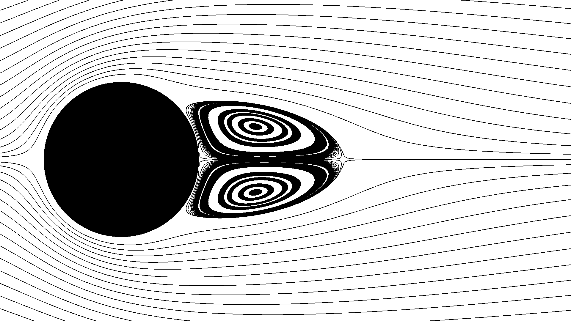
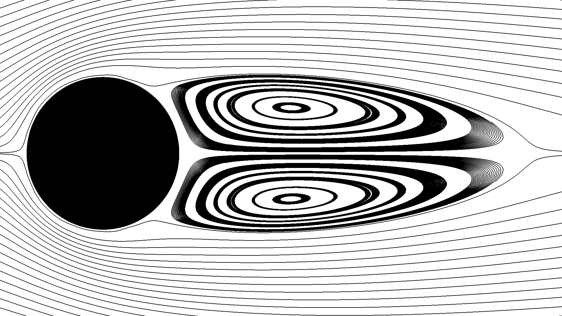
As illustrated in Fig. 6(b), the steady flows can be quantified through a variety of vortex parameters such as the vortex location , vortex distance , length of separation , and angle of separation . In addition, the drag coefficient can be used to validate the force behaviour, where is the -component of the total force acting on the cylinder.


The predicted local streamlines of the steady flows at Reynolds numbers and are shown in Fig. 7. As the Reynolds number increases, the attached, steady, and symmetric vortex pair grow in length. A comparison of the predicted flow properties with the published ones in the literature is presented in Table 1, in which excellent agreement is presented among all the quantities of interest.
| Coutanceau and Bouard [38]∗ | |||||
|---|---|---|---|---|---|
| Linnick and Fasel [39] | |||||
| Brehm et al. [37] | |||||
| Present study | |||||
| Coutanceau and Bouard [38]∗ | |||||
| Linnick and Fasel [39] | |||||
| Brehm et al. [37] | |||||
| Present study |
The temporal evolution of the unsteady flows at and are shown in Fig. 8, in which the development of von Kármán vortex shedding in the wake region is captured in detail. The unsteady flows can be quantified via several flow parameters, such as the Strouhal number , drag coefficient , and lift coefficient , where is the vortex shedding frequency (in this study, two point probes are positioned at and to record the time signals of the -component of the velocity, whose FFT are then used to determine the vortex shedding frequency) and is the -component of the total force acting on the cylinder, respectively. A comparison of flow results is shown in Table 2, in which good agreement is obtained.
| Berger and Wille [40]∗ | |||
|---|---|---|---|
| Linnick and Fasel [39] | |||
| Brehm et al. [37] | |||
| Present study | |||
| Berger and Wille [40]∗ | |||
| Linnick and Fasel [39] | |||
| Brehm et al. [37] | |||
| Present study |
4.2 Supersonic shock-sphere interaction
As illustrated in Fig. 9, the unsteady drag force and pressure history acting on a radius sphere suspended in a test region and impacted by a Mach planar incident shock are studied to validate the proposed field function applied to supersonic fluid-solid interactions. The center of the sphere overlaps with the center of the test region and is at the origin position , and the incident shock is initially positioned at . The pre-shock and post-shock states are and , respectively. The drag coefficient is computed as , where is the -component of the total force acting on the sphere.


Tanno et al. [41] experimentally measured the drag coefficient and pressure history using a shock tube facility. In addition, employing a curvilinear grid and the axisymmetric Navier–Stokes equations, they also numerically simulated the flow with the no-slip wall boundary condition and reported the obtained drag coefficient. In this study, Cartesian grids are used. To achieve an affordable computational cost, the Euler equations with the slip-wall boundary condition are applied instead. Since the viscous effect is very limited in this supersonic flow, and the pressure force dominants the shock-sphere interaction [41], the inviscid flow assumption is suggested to be adequate. Three levels of grids, , , and , were used to test the asymptotic range of convergence. The grid, which has a grid resolution of about ( nodes per diameter) was found to be sufficient, and its numerical results are reported below.


The evolution of the shock front through an iso-surface of the numerical Schlieren field is captured in Fig. 10, in which the reflection and diffraction of the shock wave along sphere surface and the formation of wake by shock collision are clearly illustrated. A comparison of the predicted pressure variation at the two probe locations with the experimental measurements in reference [41] is shown in Fig. 11. For , the numerical pressure data closely resemble the experimental ones, including both the arrival time and the value of the peak pressures. At the later stage, the numerical and experimental results present moderate discrepancies. A further comparison of the predicted drag coefficient with the experimental and numerical data in reference [41] is captured in Fig. 12. The obtained drag coefficient herein is consistent with the numerical result in [41], and the two numerical results both agree very well with the experimental measurement. It is worth noting that, in the reference [41], compared to the pressure measurement, a model configuration less affecting the flow was used in the drag measurement, which might be one of the reasons leading to the different levels of agreement between the numerical and experimental data on pressure and drag coefficient at the late stage of evolution.
4.3 A multibody contact and collision system
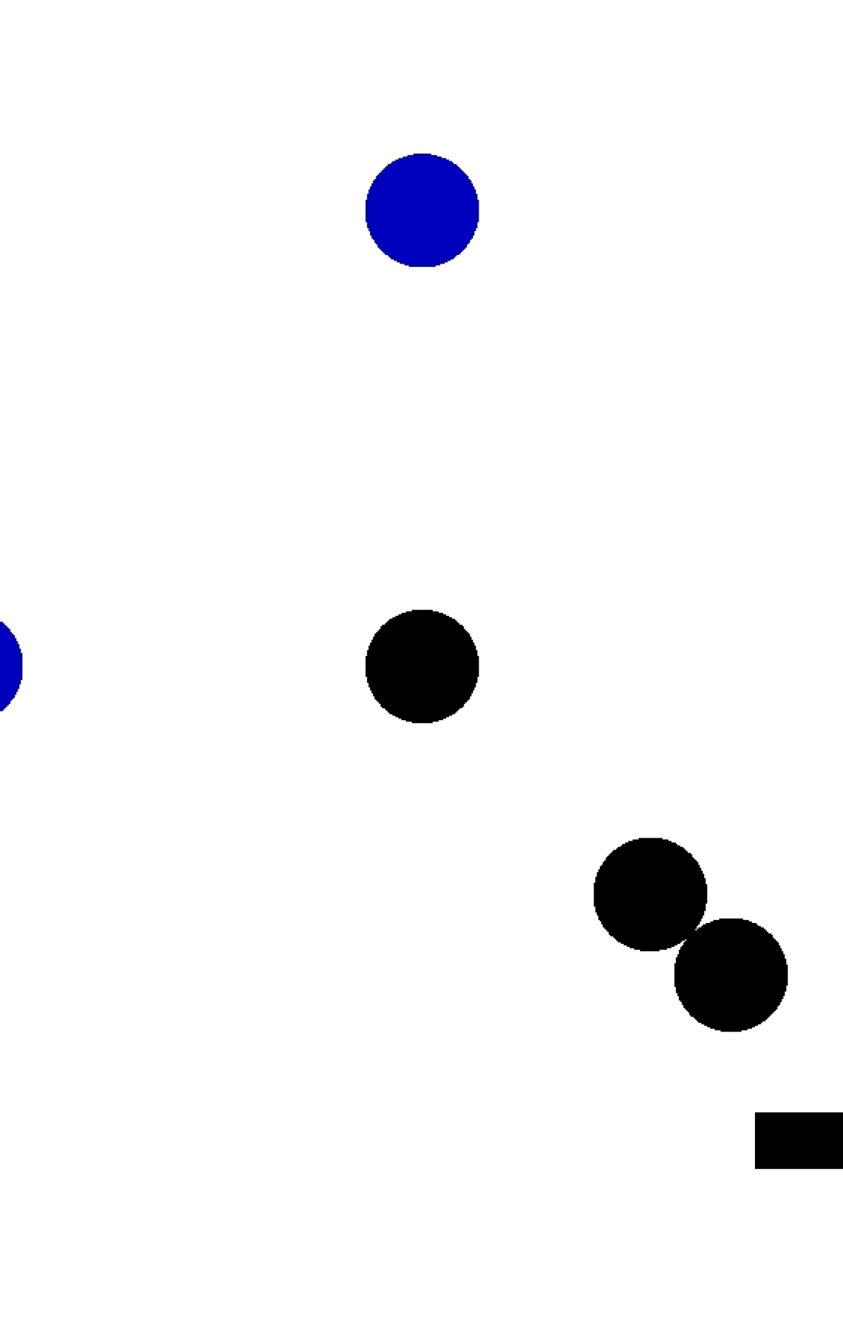
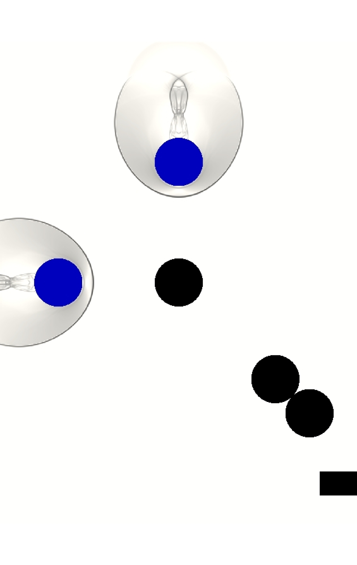
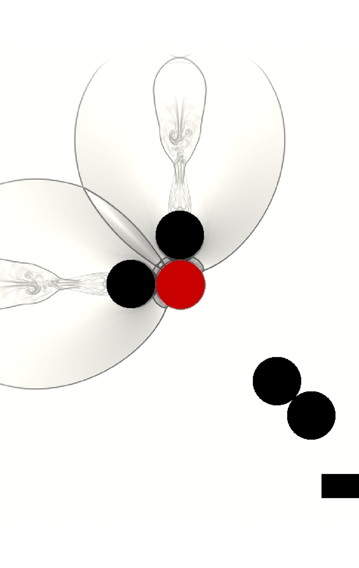
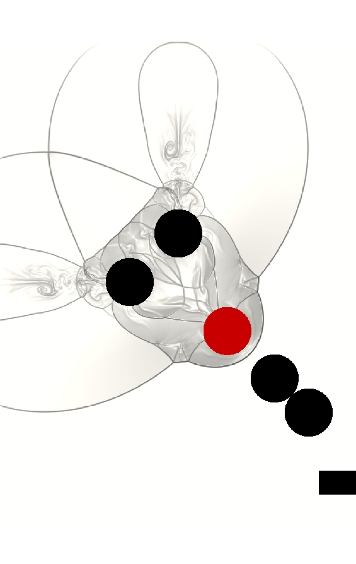
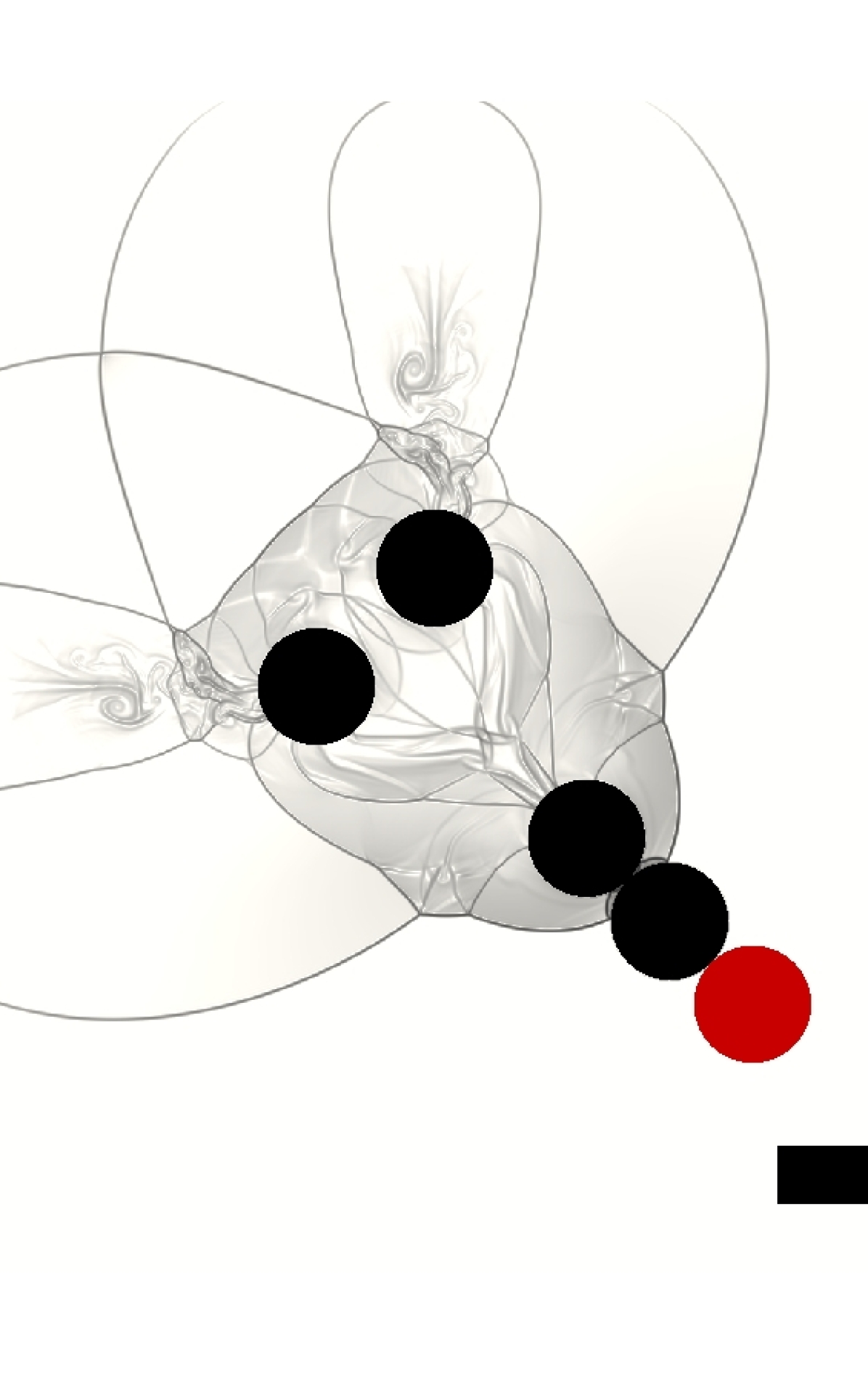
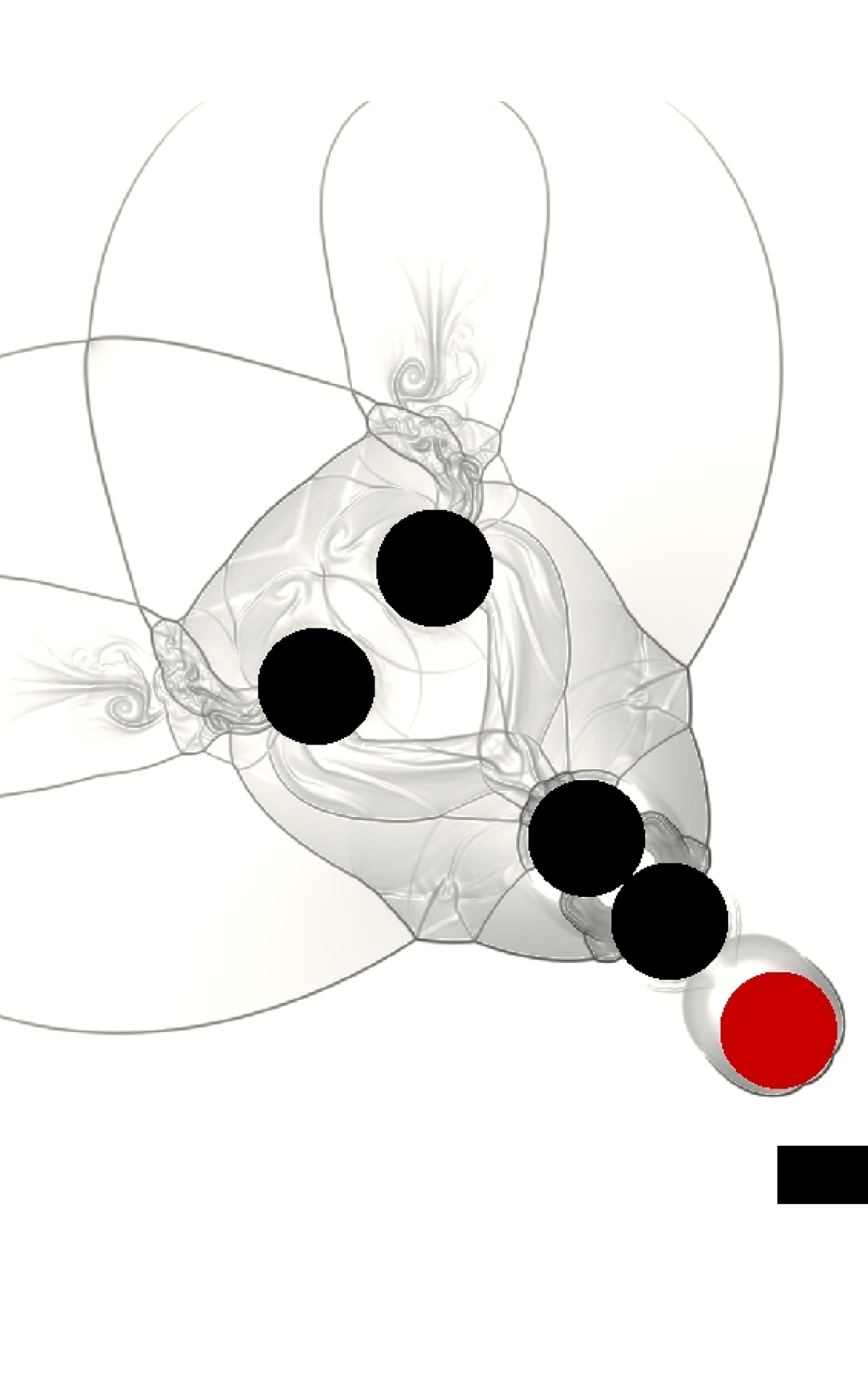
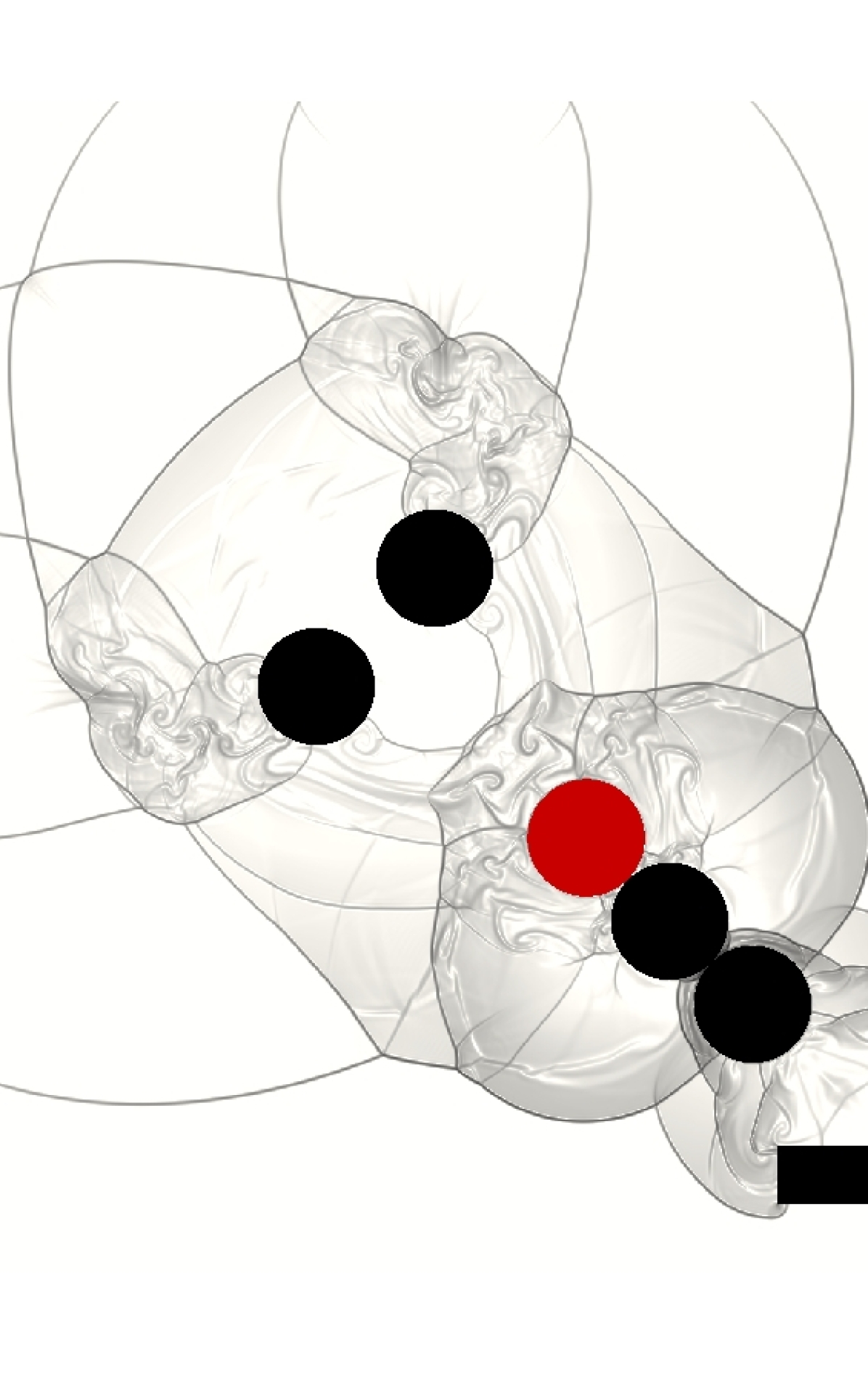
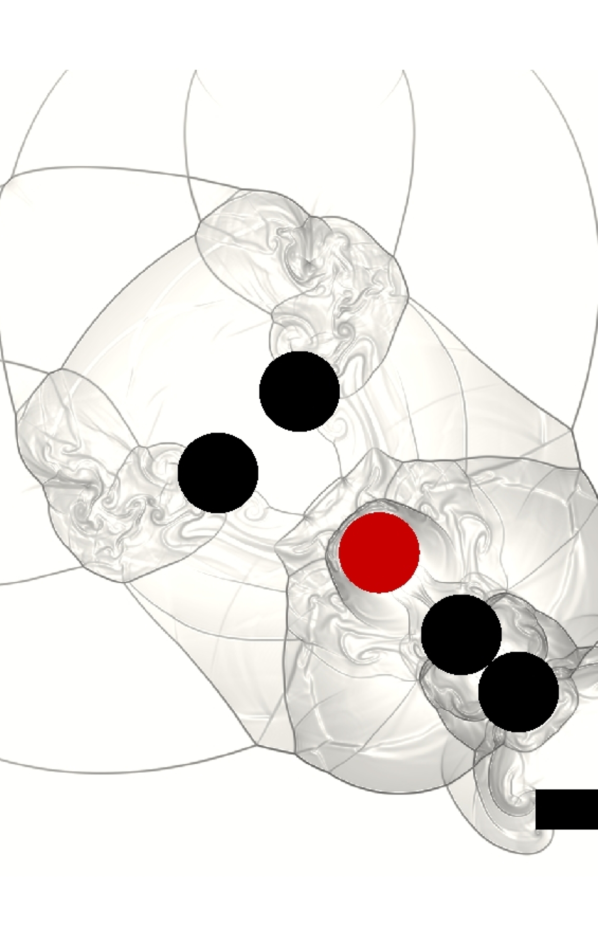
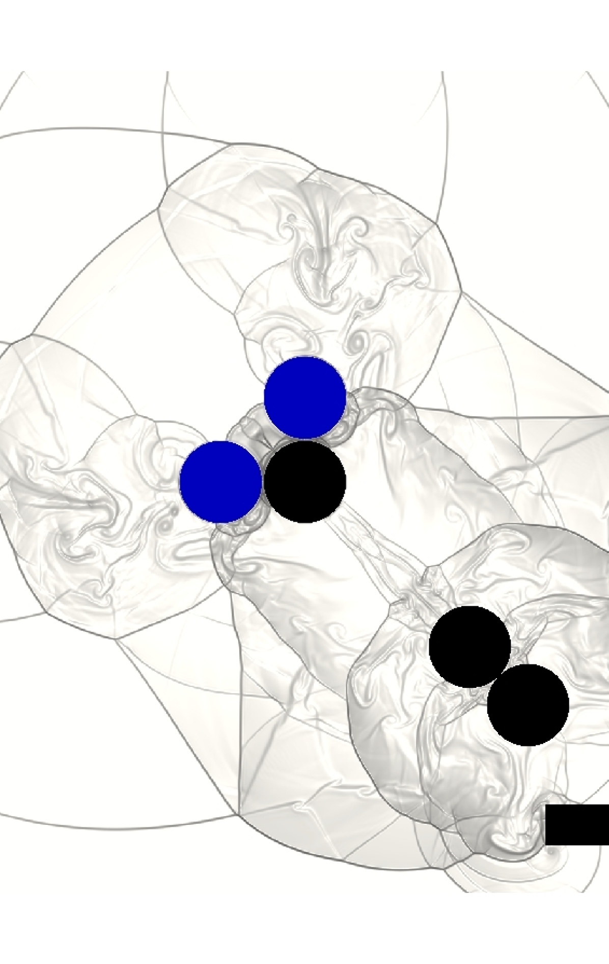
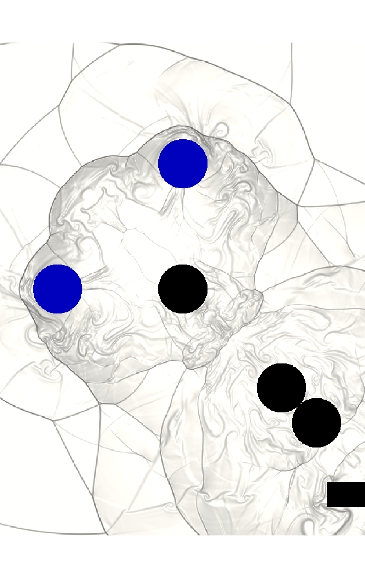
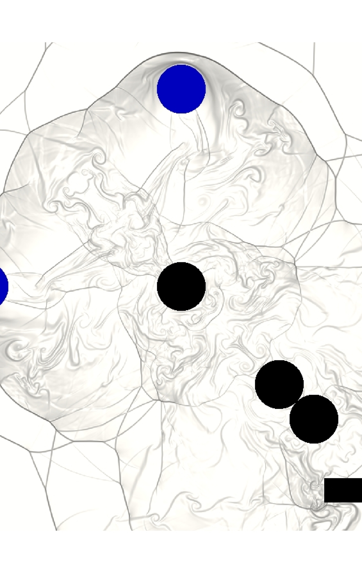
As illustrated in Fig. 13, a fluid-solid system is designed to examine the applicability of the field function for multicontact and collision scenarios. In a domain, the gas filling the domain has the initial state , in which the speed of sound is , and the flow is assumed to be inviscid. In addition, five identical and cylindrical solids with diameter and a -angled wall are placed in the domain. The centers of the solids are , , , , and , respectively. The inner corner of the wall locates at .

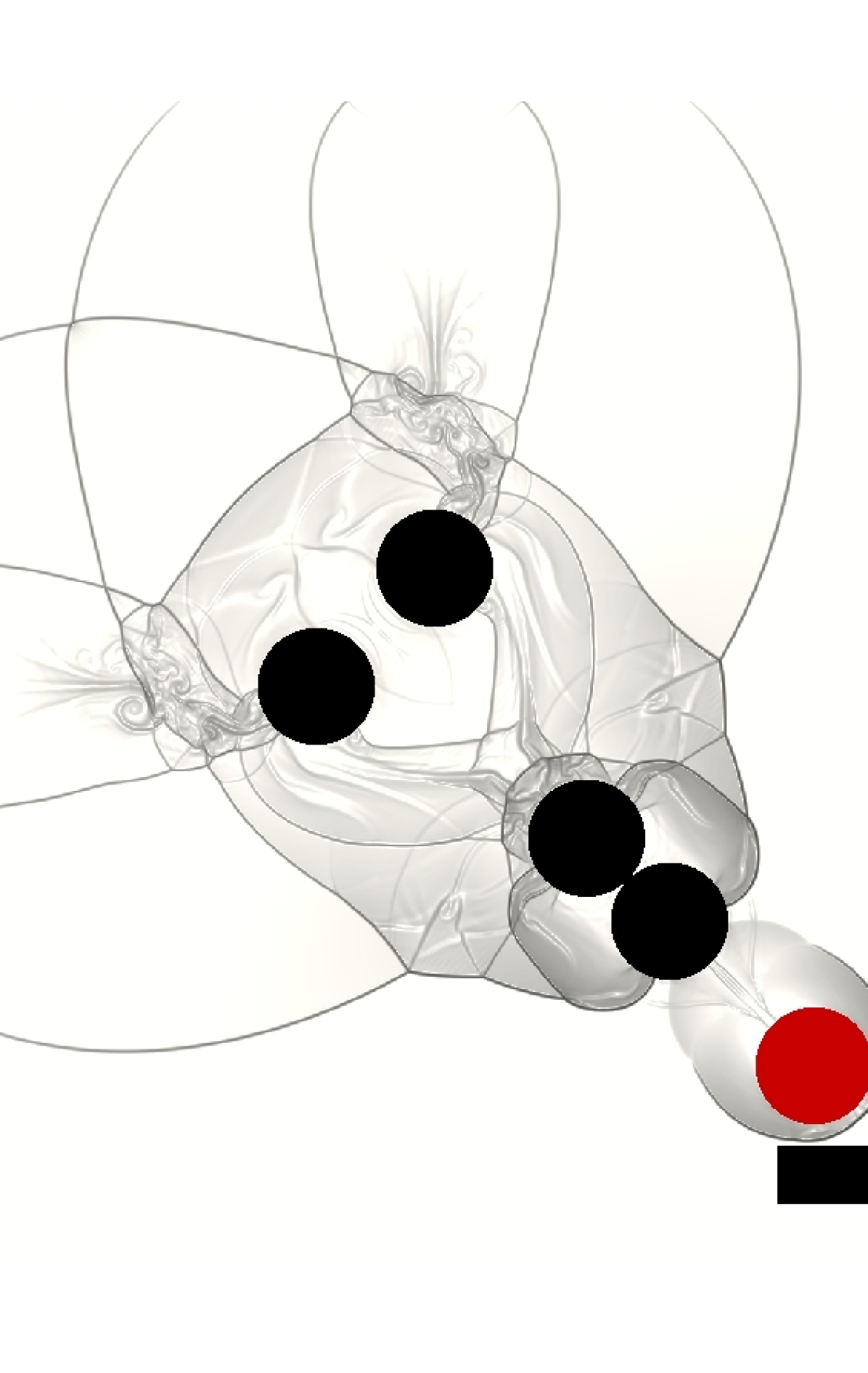
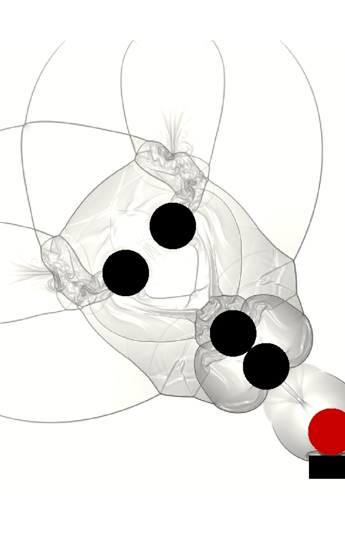
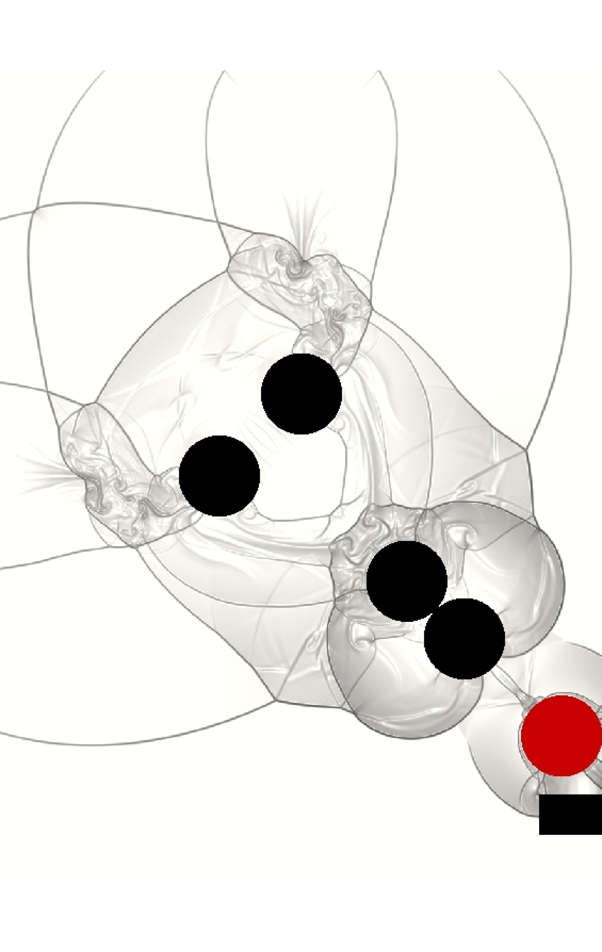
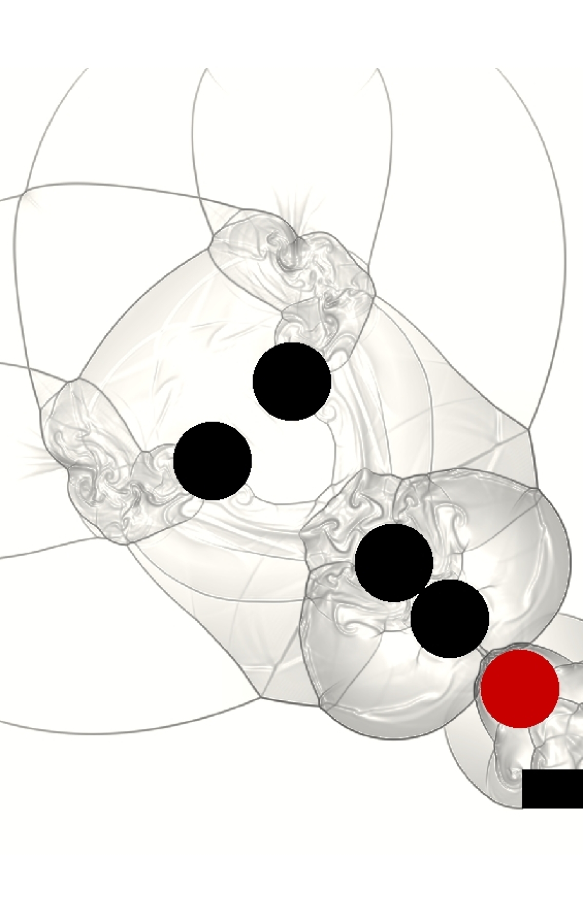
The solids and have an initial velocity magnitude , which corresponds to a Mach number of . The solids , , and are initially stationary, and the wall is fixed in space. If all the collisions are assumed to be elastic and fluid forces acting on solids are neglected, then the motions of the solids are analytically solvable. More specifically, and will collide with simultaneously at and completely transfer their momentum to . At , with the velocity state will collide with to form a solid string consisting of , , and and instantly transfer its momentum to . At , will collide with the wall and bounce back, causing the collision sequence to be inverted. At , with the velocity state will collide with to form a solid string consisting of , , and and instantly transfer its momentum to . At , will collide with and simultaneously and completely transfer its -momentum to and -momentum to . At , and travel back to their initial positions.
The evolution process of this designed system involves multibody collisions with momentum transfer at both aligned and angled directions. In addition, the collision between and has two contact regions occurring simultaneously, which represents a multicontact collision and, in general, is a difficult problem to solve in rigid-body dynamics. Therefore, this fluid-solid system is solved to on a grid to test the proposed field function.
As captured in Fig. 14, the proposed field function can successfully facilitate the solution of the fluid-solid system, and the collision detection and response algorithms based on the field function can correctly resolve the multibody contact and collisions. In the numerical results recorded in Table 3, the velocity states of all the solids are predicted exactly. The maximum position error of the solid centers happens at and and is relative to the diameter . During the solid collisions, although solid states instantly switch between and , the presented framework manages these challenging conditions successfully. As an ill-posed problem, multibody collision in general is an unsolvable problem unless additional assumptions are imposed [25]. Nonetheless, the current collision model provides a deterministic approach for approximating multibody collision response with parameterized elasticity and friction and, more importantly, effectively supports the validation of the collision detection capability of the proposed field function.
4.4 Supersonic wedge penetrating a particle bed
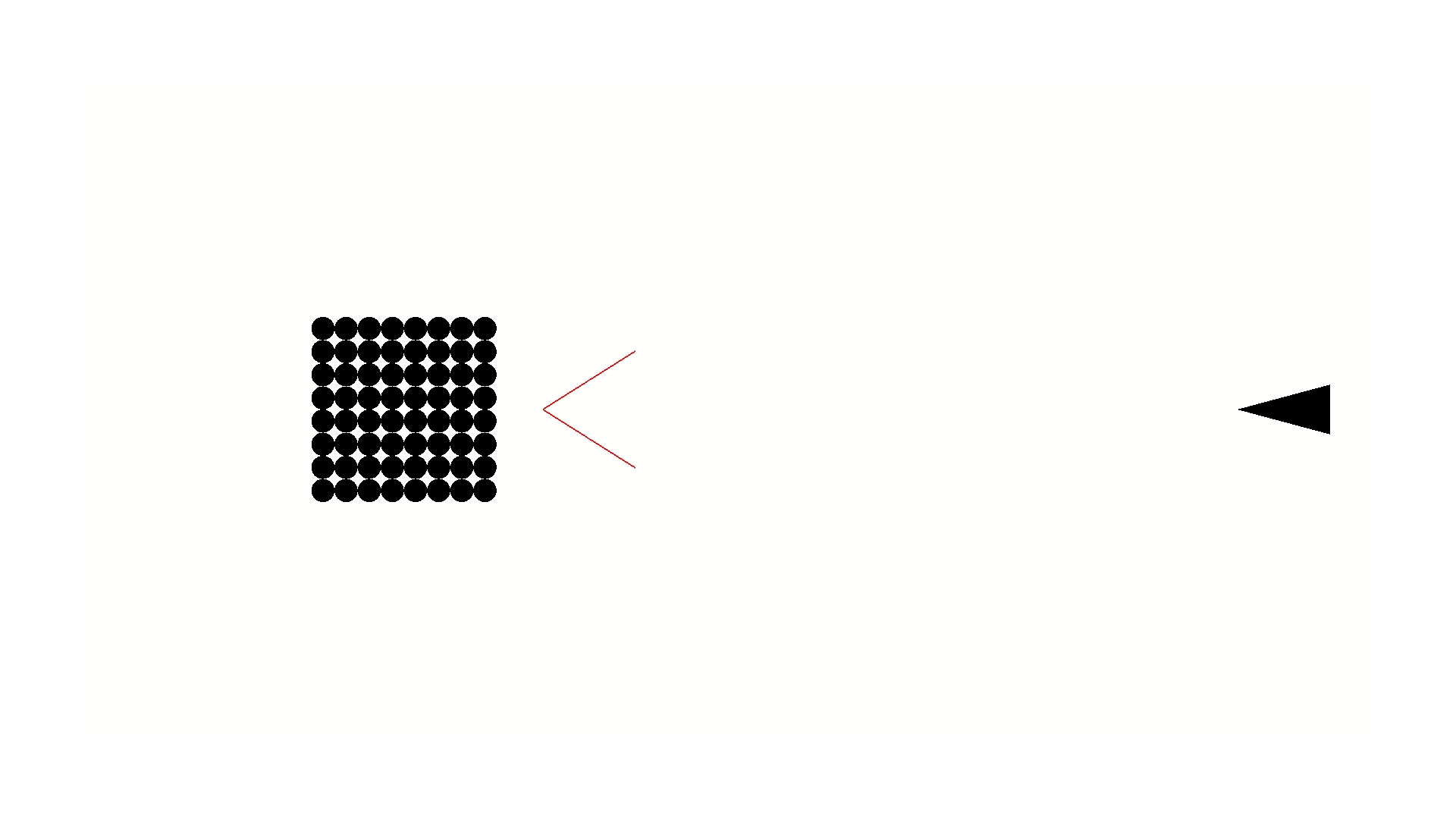
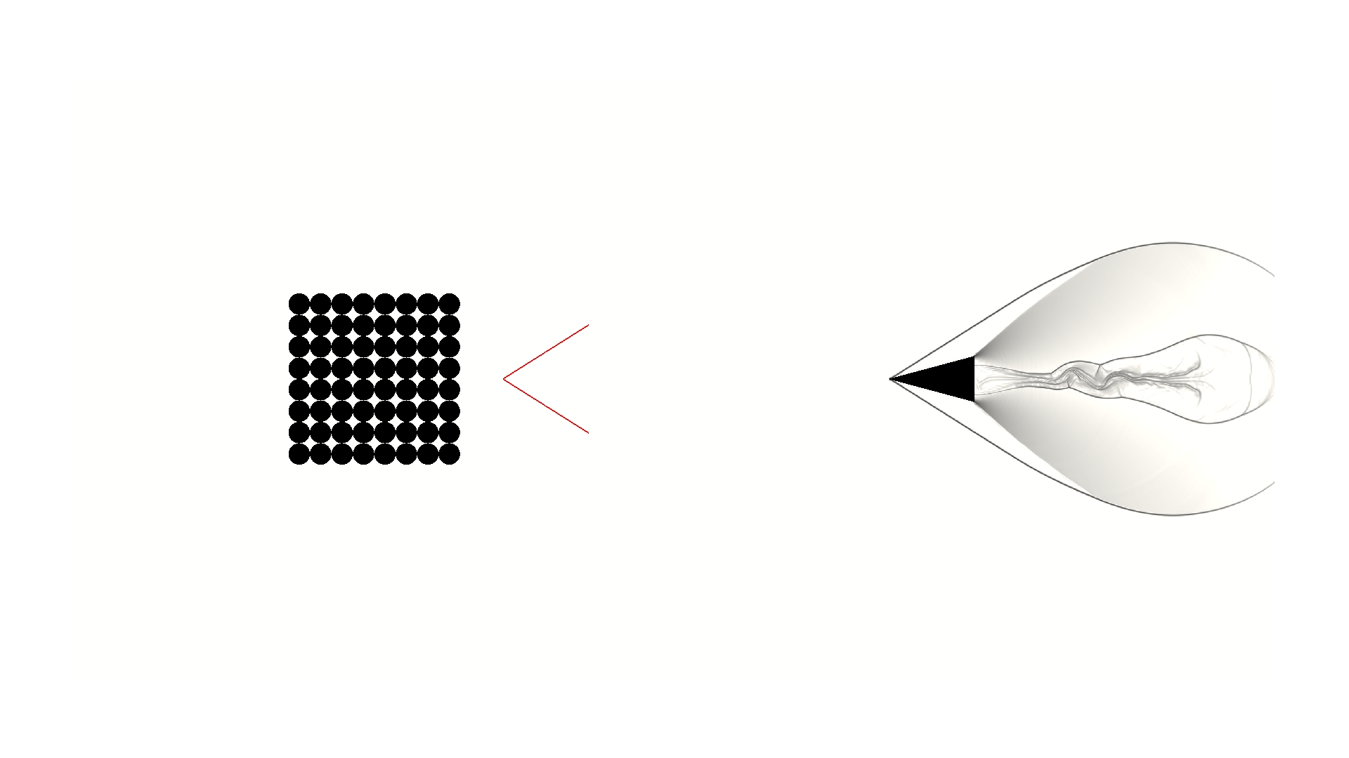
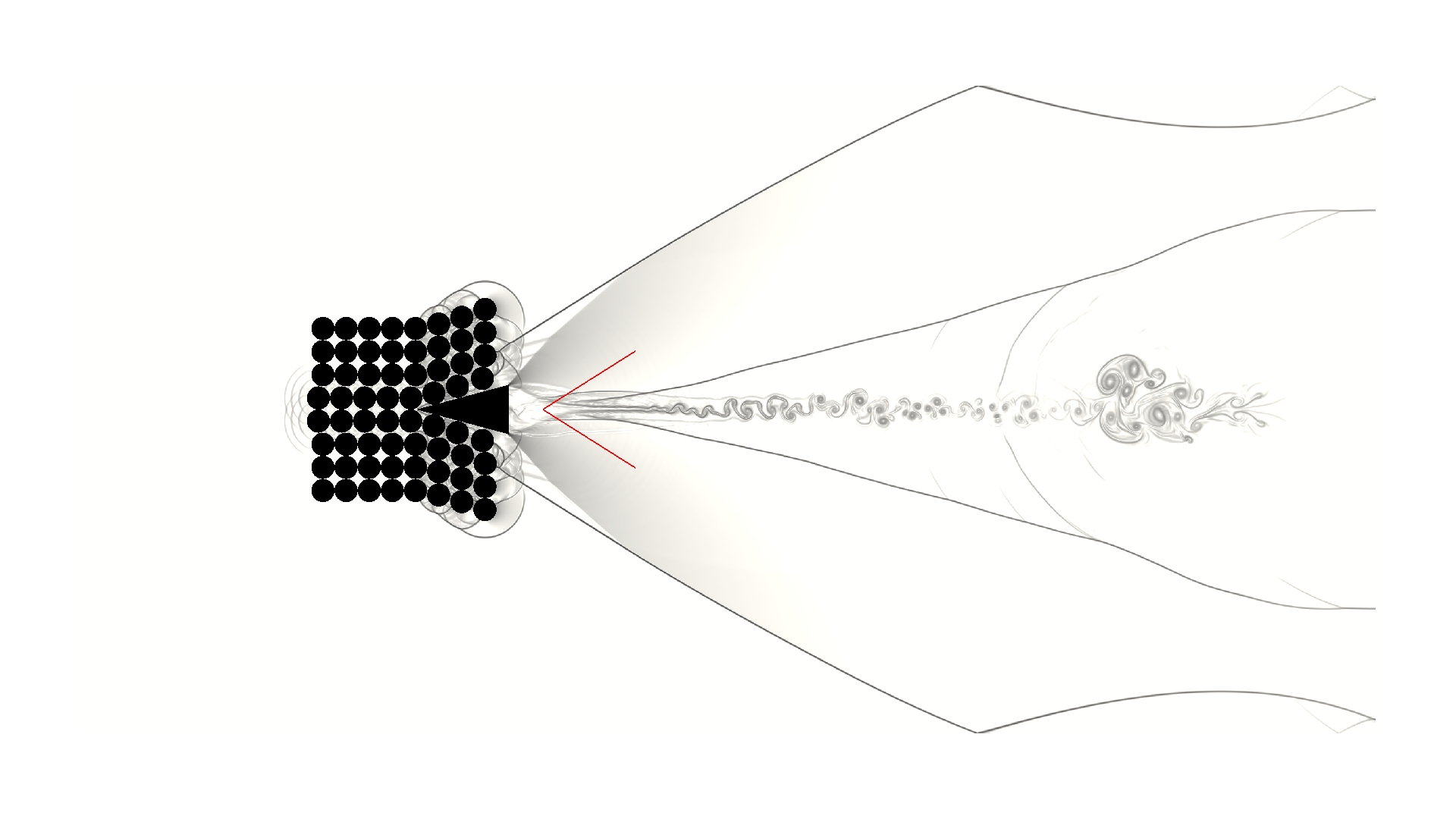
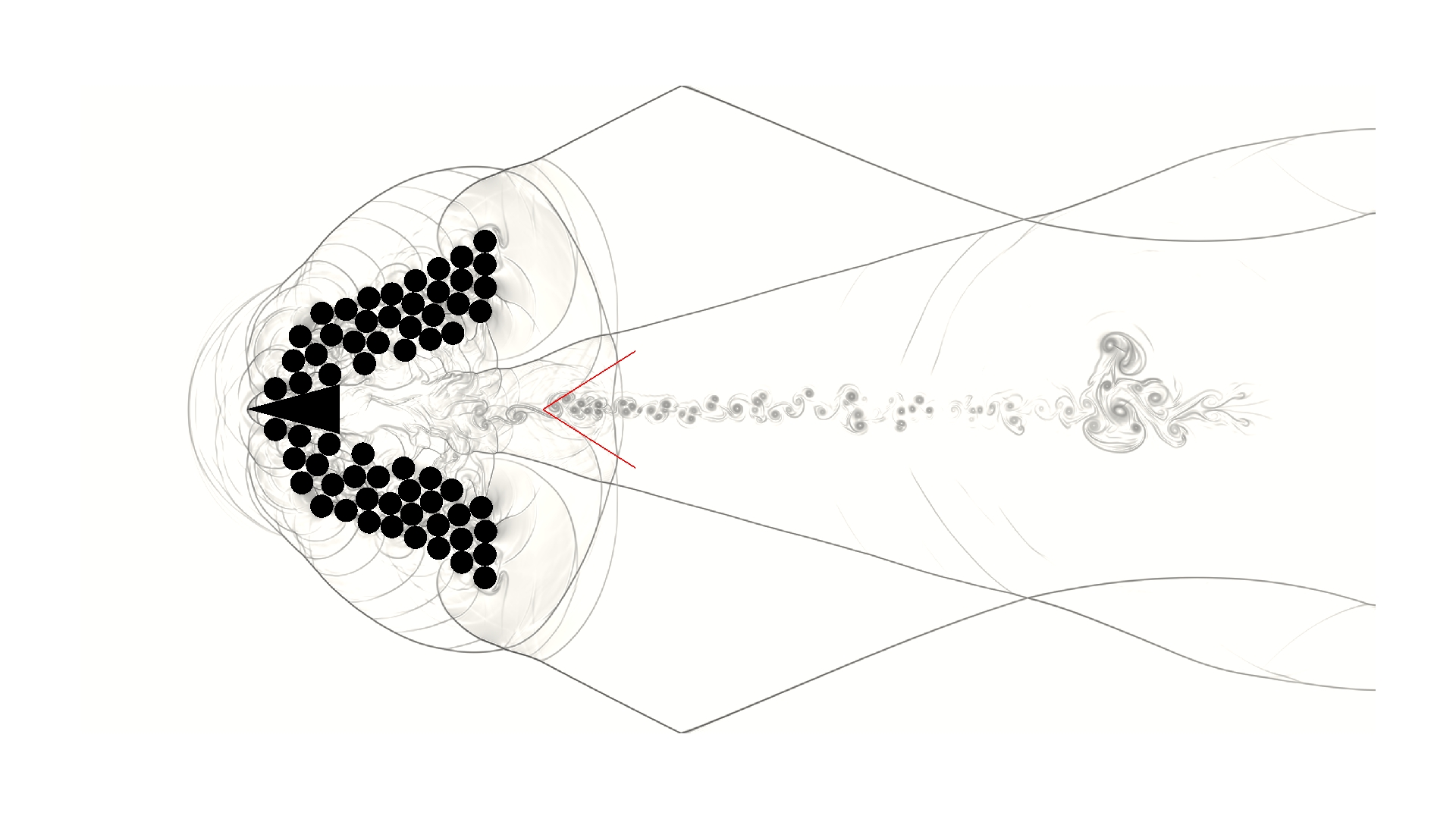
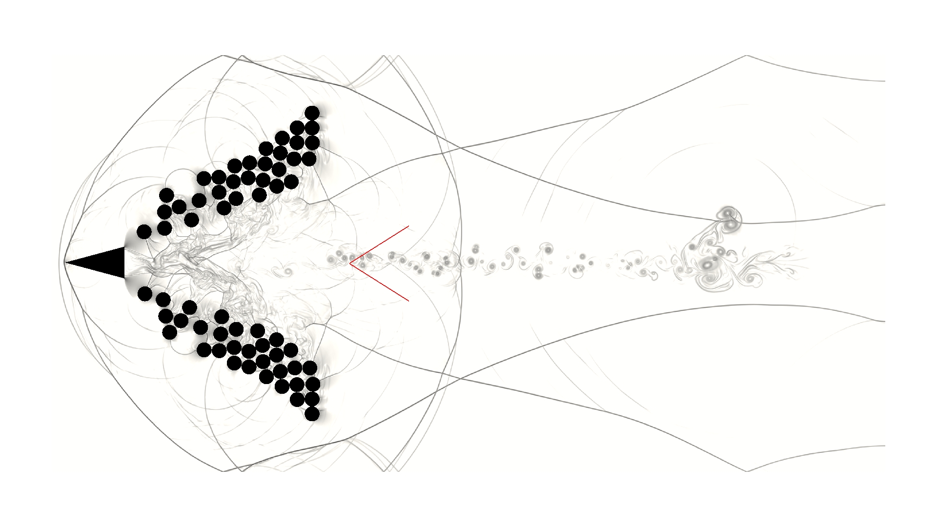
A supersonic wedge penetrating a particle bed is simulated to further demonstrate the applicability of the field function for solving complex and dynamic fluid-solid systems. As illustrated in Fig. 15, in a domain, a wedge with length and deflection angle is horizontally positioned in the domain, and the front vertex of the wedge locates at . In addition, in the region, identical cylindrical particles with diameter are tightly packed.

Initially, the gas in the domain has the state , in which the speed of sound is . The wedge has a density , a coefficient of restitution , and an initial velocity . The particles have a density , a coefficient of restitution , and zero initial velocity. The flow inside the domain is assumed to be inviscid. The slip-wall condition is imposed at the top and bottom domain boundaries as well as the wedge and particle surfaces, while the outflow condition is enforced at the left and right domain boundaries. The evolution of this fluid-solid system is solved to on a Cartesian grid.
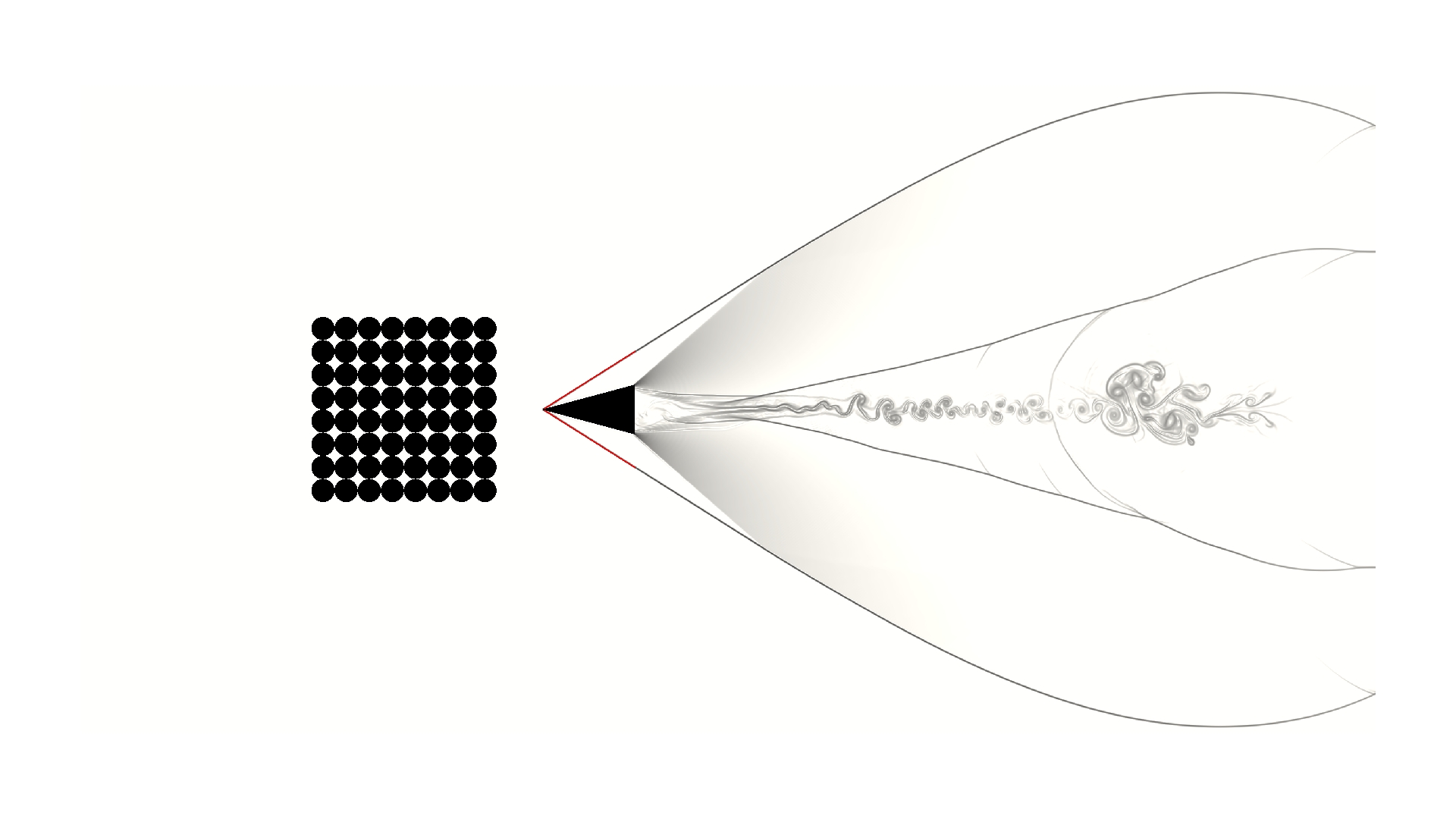
During the solution process, before the wedge collides with the particle bed (for ), the fluid forces acting on the wedge are deactivated such that the wedge can move with a constant supersonic speed. As a result, oblique shock waves generated at the nose of the moving wedge can reach a steady state with a constant shock angle . The relation satisfies the following analytical formulation [42]:
| (32) |
where is the heat capacity ratio.
The simulated time evolution of the system is captured in Fig. 16, in which the red lines represent the analytical solutions of the shock angles of the oblique shocks at position . As shown in Fig. 16(c), the predicted oblique shock angle agrees very well with the analytical solution . After the wedge collides with the particle bed, a force chain within the contacted particles is created due to the penetrating wedge. This force chain accelerates the particles and fractures the particle bed. The suddenly destabilized particle bed generates strong flow disturbances at the surrounding area, which interact with the wedge generated shocks and waves, forming complex wave diffraction and interference patterns in space. During the wedge penetrating the particle bed, intensive multibody contact and collisions are successfully simulated, and an intuitive dynamic process is presented in the solution. Moreover, the -plane symmetry is well preserved for the entire penetrating process. These results illustrate the ability of the presented field function for facilitating the solution of complex and dynamic fluid-solid systems involving coupled fluid-fluid, fluid-solid, and solid-solid interactions.
5 Conclusion
An integer-type field function has been developed to facilitate the solution of complex and dynamic fluid-solid systems on Cartesian grids with interface-resolved fluid-fluid, fluid-solid, and solid-solid interactions. The main conclusions are summarized as the following:
-
•
For a Cartesian-grid-discretized computational domain segmented by a set of solid bodies, the developed field function explicitly tracks each subdomain with multiple resolved interfacial node layers. Therefore, it is straightforward to enforce designated governing equations, constitutive models, numerical schemes, and interface conditions for each subdomain.
-
•
The presented field function enables low-memory-cost multidomain node mapping, efficient node remapping, fast collision detection, and expedient surface force integration for computing fluid-solid systems. Easy-to-implement algorithms for the field function and its described functionalities are also presented. The proposed node mapping algorithm effectively solves a generalized point-in-polyhedron problem represented by a set of points together with a set of polyhedrons. In addition, this algorithm successfully unifies the procedures of the initial multidomain node mapping and the subsequent node remapping, which can simplify the code structure and reduce the complexity of implementation.
-
•
Equipped with a deterministic multibody collision model, the applicability of the developed field function for solving complex and dynamic fluid-solid systems is validated and illustrated through numerical experiments ranging from subsonic to supersonic flows, such as the subsonic flow around a cylinder, supersonic shock-sphere interaction, a multibody contact and collision system, and a supersonic wedge penetrating a particle bed. The obtained numerical results are all in close agreement with the corresponding published numerical data, experimental observations, or analytical solutions.
Acknowledgements
Financial support of this work was provided by Natural Sciences and Engineering Research Council of Canada (NSERC) and Defence Research and Development Canada (DRDC). This work was made possible by the facilities of the Shared Hierarchical Academic Research Computing Network (SHARCNET: www.sharcnet.ca) and Compute/Calcul Canada.
References
- Glowinski et al. [2001] R. Glowinski, T. Pan, T. Hesla, D. Joseph, J. Periaux, A fictitious domain approach to the direct numerical simulation of incompressible viscous flow past moving rigid bodies: application to particulate flow, J. Comput. Phys. 169 (2) (2001) 363–426.
- van der Hoef et al. [2008] M. A. van der Hoef, M. van Sint Annaland, N. Deen, J. Kuipers, Numerical simulation of dense gas-solid fluidized beds: a multiscale modeling strategy, Annu. Rev. Fluid Mech. 40 (2008) 47–70.
- Peskin [1972] C. S. Peskin, Flow patterns around heart valves: a numerical method, J. Comput. Phys. 10 (2) (1972) 252–271.
- Rodriguez et al. [2013] V. Rodriguez, R. Saurel, G. Jourdan, L. Houas, Solid-particle jet formation under shock-wave acceleration, Phys. Rev. E 88 (6) (2013) 063011.
- Mo et al. [2017] H. Mo, F.-S. Lien, F. Zhang, D. Cronin, A numerical framework for the direct simulation of dense particulate flow under explosive dispersal, Shock Waves (2017) 1–19.
- Fedkiw et al. [1999] R. P. Fedkiw, T. Aslam, B. Merriman, S. Osher, A non-oscillatory Eulerian approach to interfaces in multimaterial flows (the ghost fluid method), J. Comput. Phys. 152 (2) (1999) 457–492.
- Fedkiw [2002] R. P. Fedkiw, Coupling an Eulerian fluid calculation to a Lagrangian solid calculation with the ghost fluid method, J. Comput. Phys. 175 (1) (2002) 200–224.
- Uhlmann [2005] M. Uhlmann, An immersed boundary method with direct forcing for the simulation of particulate flows, J. Comput. Phys. 209 (2) (2005) 448–476.
- Kempe and Fröhlich [2012] T. Kempe, J. Fröhlich, An improved immersed boundary method with direct forcing for the simulation of particle laden flows, J. Comput. Phys. 231 (9) (2012) 3663–3684.
- Mittal and Iaccarino [2005] R. Mittal, G. Iaccarino, Immersed boundary methods, Annu. Rev. Fluid Mech. 37 (2005) 239–261.
- Iaccarino and Verzicco [2003] G. Iaccarino, R. Verzicco, Immersed boundary technique for turbulent flow simulations, Appl. Mech. Rev. 56 (3) (2003) 331–347.
- Sambasivan and Udaykumar [2009] S. K. Sambasivan, H. Udaykumar, Ghost fluid method for strong shock interactions Part 2: immersed solid boundaries, AIAA J. 47 (12) (2009) 2923–2937.
- Kapahi et al. [2013] A. Kapahi, S. Sambasivan, H. Udaykumar, A three-dimensional sharp interface Cartesian grid method for solving high-speed multimaterial impact, penetration and fragmentation problems, J. Comput. Phys. 241 (2013) 308–332.
- Walton [1993] O. R. Walton, Numerical simulation of inelastic, frictional particle-particle interactions, 1993.
- Glowinski et al. [1999] R. Glowinski, T.-W. Pan, T. I. Hesla, D. D. Joseph, A distributed Lagrange multiplier/fictitious domain method for particulate flows, Int. J. Multiph. Flow 25 (5) (1999) 755–794.
- Moreno and Bombardelli [2012] P. Moreno, F. Bombardelli, 3D numerical simulation of particle-particle collisions in saltation mode near stream beds, Acta Geophys. 60 (6) (2012) 1661–1688.
- Hu et al. [2001] H. H. Hu, N. A. Patankar, M. Zhu, Direct numerical simulations of fluid–solid systems using the Arbitrary Lagrangian–Eulerian technique, J. Comput. Phys. 169 (2) (2001) 427–462.
- Lin and Gottschalk [1998] C. M. Lin, S. Gottschalk, Collision detection between geometric models: a survey, in: IMA Conference on Mathematics of Surfaces, vol. 1, 602–608, 1998.
- Jiménez et al. [2001] P. Jiménez, F. Thomas, C. Torras, 3D collision detection: a survey, Comput. Graph. 25 (2) (2001) 269–285.
- Guendelman et al. [2003] E. Guendelman, R. Bridson, R. Fedkiw, Nonconvex rigid bodies with stacking, in: ACM Trans. Graph., vol. 22, ACM, 871–878, 2003.
- Wald et al. [2007] I. Wald, S. Boulos, P. Shirley, Ray tracing deformable scenes using dynamic bounding volume hierarchies, ACM Trans. Graph. 26 (1) (2007) 6.
- Ericson [2004] C. Ericson, Real-time collision detection, CRC Press, 2004.
- Jones et al. [2006] M. W. Jones, J. A. Bærentzen, M. Sramek, 3D distance fields: a survey of techniques and applications, IEEE Trans. Vis. Comput. Graph. 12 (4) (2006) 581–599.
- Osher and Fedkiw [2001] S. Osher, R. P. Fedkiw, Level set methods: an overview and some recent results, J. Comput. Phys. 169 (2) (2001) 463–502.
- Ivanov [1995] A. Ivanov, On multiple impact, J. Appl. Math. Mech. 59 (6) (1995) 887–902.
- Courant et al. [1927] R. Courant, K. O. Friedrichs, H. Lewy, On the partial difference equations of mathematical physics, Math. Ann. 100.
- o’Rourke [1998] J. o’Rourke, Computational geometry in C, Cambridge university press, 1998.
- Carvalho and Cavalcanti [1995] P. C. P. Carvalho, P. R. Cavalcanti, Point in polyhedron testing using spherical polygons, Graphics Gems V (1995) 42–49.
- Haines [1994] E. Haines, Point in polygon strategies, Graphics Gems IV 994 (1994) 24–26.
- Baerentzen and Aanaes [2005] J. A. Baerentzen, H. Aanaes, Signed distance computation using the angle weighted pseudonormal, IEEE Trans. Vis. Comput. Graph. 11 (3) (2005) 243–253.
- Strang [1968] G. Strang, On the construction and comparison of difference schemes, SIAM J. Numer. Anal. 5 (3) (1968) 506–517.
- Shu and Osher [1988] C.-W. Shu, S. Osher, Efficient implementation of essentially non-oscillatory shock-capturing schemes, J. Comput. Phys. 77 (2) (1988) 439–471.
- Gottlieb et al. [2001] S. Gottlieb, C.-W. Shu, E. Tadmor, Strong stability-preserving high-order time discretization methods, SIAM Rev. 43 (1) (2001) 89–112.
- Jiang and Shu [1996] G.-S. Jiang, C.-W. Shu, Efficient implementation of weighted ENO schemes, J. Comput. Phys. 126 (1).
- Mo et al. [2016] H. Mo, F.-S. Lien, F. Zhang, D. Cronin, An immersed boundary method for solving compressible flow with arbitrarily irregular and moving geometry, arXiv preprint arXiv:1602.06830 .
- Gao et al. [2007] T. Gao, Y.-H. Tseng, X.-Y. Lu, An improved hybrid Cartesian/immersed boundary method for fluid-solid flows, Int. J. Numer. Meth. Fluids 55 (12) (2007) 1189–1211.
- Brehm et al. [2015] C. Brehm, C. Hader, H. F. Fasel, A locally stabilized immersed boundary method for the compressible Navier–Stokes equations, J. Comput. Phys. 295 (2015) 475–504.
- Coutanceau and Bouard [1977] M. Coutanceau, R. Bouard, Experimental determination of the main features of the viscous flow in the wake of a circular cylinder in uniform translation. Part 1. Steady flow, J. Fluid Mech. 79 (02) (1977) 231–256.
- Linnick and Fasel [2005] M. N. Linnick, H. F. Fasel, A high-order immersed interface method for simulating unsteady incompressible flows on irregular domains, J. Comput. Phys. 204 (1) (2005) 157–192.
- Berger and Wille [1972] E. Berger, R. Wille, Periodic flow phenomena, Annu. Rev. Fluid Mech. 4 (1) (1972) 313–340.
- Tanno et al. [2003] H. Tanno, K. Itoh, T. Saito, A. Abe, K. Takayama, Interaction of a shock with a sphere suspended in a vertical shock tube, Shock Waves 13 (3) (2003) 191–200.
- Anderson Jr [2010] J. D. Anderson Jr, Fundamentals of aerodynamics, Tata McGraw-Hill Education, New York, 2010.