Dune-CurvilinearGrid
Parallel Dune Grid Manager for
Unstructured Tetrahedral Curvilinear Meshes
Aleksejs Fominsa,b and Benedikt Oswaldb
a Nanophotonics and Metrology Laboratory (nam.epfl.ch), Ecole Polytechnique Féderale de Lausanne (EPFL), Switzerland
b LSPR AG, Grubenstrasse 9, CH-8045 Zürich, Switzerland.
Phone +41 43 366 90 74
email: aleksejs.fomins@epfl.ch and benedikt.oswald@lspr.ch
![[Uncaptioned image]](/html/1612.02967/assets/images/frontpage.png)
List of Acronyms
LSPR - Localised Surface Plasmon Resonance
DUNE - Distributed Unified Numerical Library
PDE - Partial Differential Equation
DoF - Degree of Freedom
HTVFE - Hierarchical Tangential Vector Finite Elements
FDTD - Finite Difference Time Domain
FEM - Finite Element Method
SIE - Surface Integral Equation (Method)
CG - Continuous Galerkin
DG - Discontinuous Galerkin
DGTD - Discontinuous Galerkin Time Domain
DGFD - Discontinuous Galerkin Frequency Domain
ABC - Absorbing Boundary Condition
BI - Boundary Integral
FEBI - Finite Element Boundary Integral
MPI - Message Passing Interface
POD - Plain Old Datatype
RAM - Random Access Memory
GPU - Graphical Processing Unit
CAD - Computer-Aided Design
GSL - GNU Standard Library
STL - Standard Template Library
GPL - General Public License
EPFL - École Polytechnique Fédérale de Lausanne
NAM - Nanophotonics and Metrology (Laboratory, EPFL)
EDPO - Ecole Doctorale Photonique (EPFL)
ABSTRACT - We introduce the dune-curvilineargrid module. The module provides the self-contained, parallel grid manager dune-curvilineargrid, as well as the underlying elementary curvilinear geometry module dune-curvilineargeometry. Both modules are developed as extension of the DUNE [3] project, and conform to the generic dune-grid and dune-geometry interfaces respectively. We expect the reader to be at least briefly familiar with the DUNE interface to fully benefit from this paper.
dune-curvilineargrid is a part of the computational framework developed within the doctoral thesis of Aleksejs Fomins. The work is fully funded by and carried out at the technology company LSPR AG. It is motivated by the need for reliable and scalable electromagnetic design of nanooptical devices, achieved by HADES3D family of electromagnetic codes. It is of primary scientific and industrial interest to model full 3D geometric designs as close to the real fabricated structures as possible. Curvilinear geometries improve both the accuracy of modeling smooth material boundaries, and the convergence rate of PDE solutions with increasing basis function order [9], reducing the necessary computational effort. Additionally, higher order methods decrease the memory footprint of PDE solvers at the expense of higher operational intensity, which helps in extracting optimal performance from processing power dominated high performance architectures [30].
dune-curvilineargeometry is capable of modeling simplex entities (edges, triangles and tetrahedra) up to polynomial order 5 via hard-coded Lagrange polynomials, and arbitrary order via analytical procedures. Its most notable features are local-to-global and global-to-local coordinate mappings, symbolic and recursive integration, symbolic polynomial scalars, vectors and matrices (e.g. Jacobians and Integration Elements).
dune-curvilineargrid uses the dune-curvilineargeometry module to provide the following functionality: fully parallel input of curvilinear meshes in the gmsh [10] mesh format, processing only the corresponding part of the mesh on each available core; mesh partitioning at the reading stage (using ParMETIS [21, 16]); unique global indices for all mesh entities over all processes; Ghost elements associated with the interprocessor boundaries; interprocessor communication of data for shared entities of all codimensions via the standard DUNE data handle interface. There is also significant support for Boundary Integral (BI) codes, allowing for arbitrary number of interior boundary surfaces, as well as all-to-all dense parallel communication procedures.
The dune-curvilineargrid grid manager is continuously developed and improved, and so is this documentation. For the most recent version of the documentation, as well as the source code, please refer to the following repositories
http://www.github.com/lspr-ag/dune-curvilineargeometry
http://www.github.com/lspr-ag/dune-curvilineargrid
and our website
Acknowledgements - While the architecture, implementation and down-to-earth programming work for dune-curvilineargrid grid manager is credited to Aleksejs Fomins and Benedikt Oswald, both authors are pleased to acknowledge the inspiration and support from the wider DUNE community. We mention names in alphabetical order and sometimes associated with a specific subject. In case we have forgotten to acknowledge an important contributor we kindly ask you to inform us and we will be happy to insert the name immediately. Here we are:
Peter Bastian, Professor at University of Heidelberg, Germany for initial suggestion to consider curvilinear tetrahedral grids in order to reduce the computational burden of the complex linear solver;
Markus Blatt, Heidelberg, Germany based independent high performance computing and DUNE contractor, for numerous hints related to the build system and DUNE architecture;
Andreas Dedner, professor, University of Warwick, United Kingdom, for numerous hints related to the DUNE architecture;
Christian Engwer, professor, University of Münster, Germany, for fruitful discussions on DUNE and dune-curvilineargrid interface;
Jorrit ’Hippi Joe’ Fahlke, postdoctoral scientist, University of Münster, Germany, for numerous hints related to the DUNE architecture, grid API, grid testing and many other fields;
Christoph Grüniger, doctoral student, University of Stuttgart, Germany for support with DUNE internal implementation;
Dominic Kempf, doctoral student, University of Heidelberg, Germany for support w.r.t grid API implementation in DUNE, especially w.r.t CMake;
Robert Klöfkorn, senior research scientist, IRISI, Norway, for support w.r.t grid API implementation in DUNE;
Steffen Müthing, postdoctoral scientist, University of Heidelberg, Germany for support with DUNE internal implementation;
Martin Nolte, postdoctoral scientist, University of Freiburg im Breisgau, Germany, for numerous hints related to the DUNE architecture;
Oliver Sander, professor, TU Dresden, Germany, for numerous hints related to the DUNE architecture, numerical integration and quadrature;
Also we would like to express special gratitude to Prof. Olivier Martin for supervising the thesis of Aleksejs Fomins, and to Prof. Emeritus. Jörg Waldvogel, who has spent significant amounts of his private time and even visited our company in order to enlighten us about the deep details of numerical integration. We would like to acknowledge enormous support from other software communities, especially Xiaoye Sherry Li for support with SuperLUDist project, George Karypis for support with ParMETIS and Steven G. Johnson for support with his GSL cubature implementation. Finally we would like to express our gratitude to Prof. Torsten Hoefler for advices on newest MPI standards, and Prof. Ralf Hiptmair for fruitful discussions on PDE solvers, including integration.
LEGAL NOTICE - The development of the dune-curvilineargrid grid manager is sponsored and fully funded by the technology company LSPR AG, Grubenstrasse 9, CH-8045 Zürich, Switzerland. LSPR AG exclusively holds all rights associated with dune-curvilineargrid. The dune-curvilineargrid fully parallel grid manager is publicly available via Github and is a free software based on the GPLv2 license. Other licenses can be negotiated through curvilinear-grid@lspr.swiss. We herewith exclude any liability on the part of LSPR AG since the software is made available as is. Any user uses the software at his own risk and by no means LSPR AG assumes any responsibility for harmful consequences or any other damage caused by the use of the software. The whole project is governed by Swiss Law. We reject any attempt of any other sovereign law to cover what we do.
1 Introduction
Integrating curvilinear geometries into modeling software is an involved multi-level process. It requires meshing software capable of creating accurate higher order elements from analytic designs or experimental data, a curvilinear grid manager able to efficiently manipulate such elements, as well as a PDE solver able to benefit from the curved geometries. The latter is mainly achieved by means of curvilinear basis functions able to accurately describe the associated vector fields (e.g. div or curl-conforming), adapting to the non-linear "bending of space". Ideas of using curvilinear grids first appeared in the literature in the 1970s [8, 17] and have been used in electromagnetic simulations for at least two decades [26].
An impressive example of using a curvilinear -dimensional code together with DG and optimized for parallel GPU processing can be found in the aerodynamics community [29]. Wang et al [27] demonstrate a 3D curvilinear parallel DGTD (Time-Domain) code for solving Maxwell’s equations in a homogeneous medium. Nevertheless, in electromagnetic community curvilinear grids are much less widespread than linear, predominantly used in 2D codes [28]. We believe that the associated challenges are as follows
- •
-
•
Standard functionality of a grid manager, such as interpolation, local-to-global and global-to-local mappings, integration, calculation of normals and basis functions becomes significantly more difficult in the curvilinear case; additional numerical tools, such as Lagrange interpolation, adaptive integration, symbolic polynomial manipulation, and optimization algorithms are needed to provide the desired functionality.
-
•
In order to fully benefit from the curvilinear geometries through reducing the total element count, basis functions of order sufficient to resolve the detailed structure of the field are necessary. The widely used CG-based codes require a divergenceless curvilinear basis of flexible order that preserves the field continuity across the element boundary. At the moment of writing authors are not aware of publications presenting such a basis. Fahs[9] implements a serial 2D and 3D curvilinear DGTD code using polynomially-complete basis, and studies the scaling of the accuracy of electromagnetic benchmarks (Mie scattering and layered Mie scattering) depending on -refinement. He finds that only in curvilinear geometries increasing the basis function order significantly improves the solution accuracy.
Until recently, literature presents implementations of curvilinear electromagnetic DGFD codes with several simplifications, limiting the flexibility and detail achievable with moderate computational resources.
The major objective for a PDE solver optimization is the improvement of accuracy of the PDE solution given a limited computational resource, and curvilinear geometries can offer that. The curvilinear material boundaries decrease or fully eliminate the artificially high jump in the surface derivatives fig. 2, avoiding the unphysical "corner effects" [25, 12]. Otherwise, the corners have to be smoothened by high h-refinement, which leads to unnecessarily high number of Degrees of Freedom (DoF).
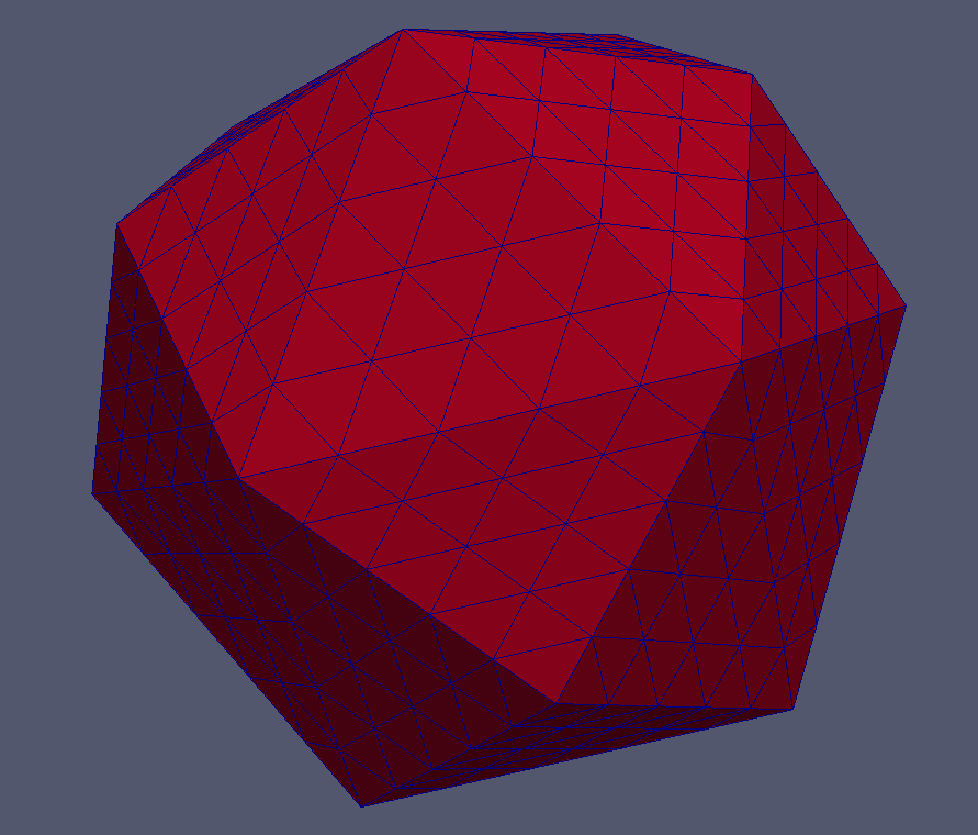
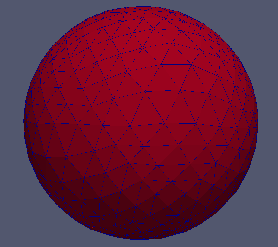
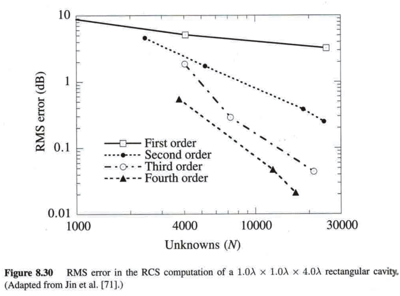
Further, the accuracy of a PDE solution improves much faster with increasing basis function order (p-refinement) than with increasing element number (h-refinement) [12], fig. 3. Fahs [9] shows that, in case of curved material boundaries, this effect can only be exploited if the corresponding element geometries are of sufficiently high order fig. 4.

1.1 Capabilities of CurvilinearGrid
The dune-curvilineargrid is a self-consistent grid manager supporting 3D tetrahedral curvilinear grids. It depends on the core modules of DUNE [3], as well as an external parallel mesh partition library ParMETIS[21, 16]. dune-curvilineargrid also depends on dune-curvilineargeometry, which we developed as a separate DUNE module.
dune-curvilineargeometry is capable of interpolating and performing multiple geometric operations over curvilinear simplex entities (edges, triangles and tetrahedra) of orders 1-5 via hard-coded Lagrange polynomials, and arbitrary order simplex entities via analytic Lagrange interpolation method. dune-curvilineargeometry complies with the standard dune-geometry interface, providing methods for local-to-global and global-to-local coordinate mapping, computation of the Jacobian matrix, integration element and entity volume. dune-curvilineargeometry has non-cached and cached implementations, where the cached version pre-computes the local-to-global map and its determinant, thus performing considerably faster for integration and mapping tasks. In comparison with the standard dune-geometry, dune-curvilineargeometry provides methods to obtain either all interpolatory vertices of an entity or only its corners, as well as the method to obtain the curvilinear order. Additionally, dune-curvilineargeometry provides the methods to obtain the outer normals of subentities of the geometry, and the subentity geometries themselves. Another feature of dune-curvilineargeometry is the symbolic polynomial class and associated differential methods, which allow to obtain analytical expressions for local-to-global map and associated integration element, enabling exact manipulation of geometries of arbitrary order. dune-curvilineargeometry contains its own recursive integration tool, wrapping the quadrature rules provided by dune-geometry. The reason for implementing this functionality is to accurately treat non-polynomial integrands for which the optimal polynomial order required for the desired accuracy is not known. In particular, it happens that curvilinear integration elements are non-polynomial in the general case (see section 2.3). The recursive integration scheme is capable to simultaneously integrate multidimensional integrands, such as vectors and matrices. This is highly useful, for example, for integrating outer product matrices. For such matrices the evaluation of all matrix elements at a given coordinate only requires expensive function evaluations. dune-curvilineargeometry provides a utility for testing curvilinear entities for self-intersection. This is done by sampling the value of integration element across the entity, and ensuring that it never changes sign.
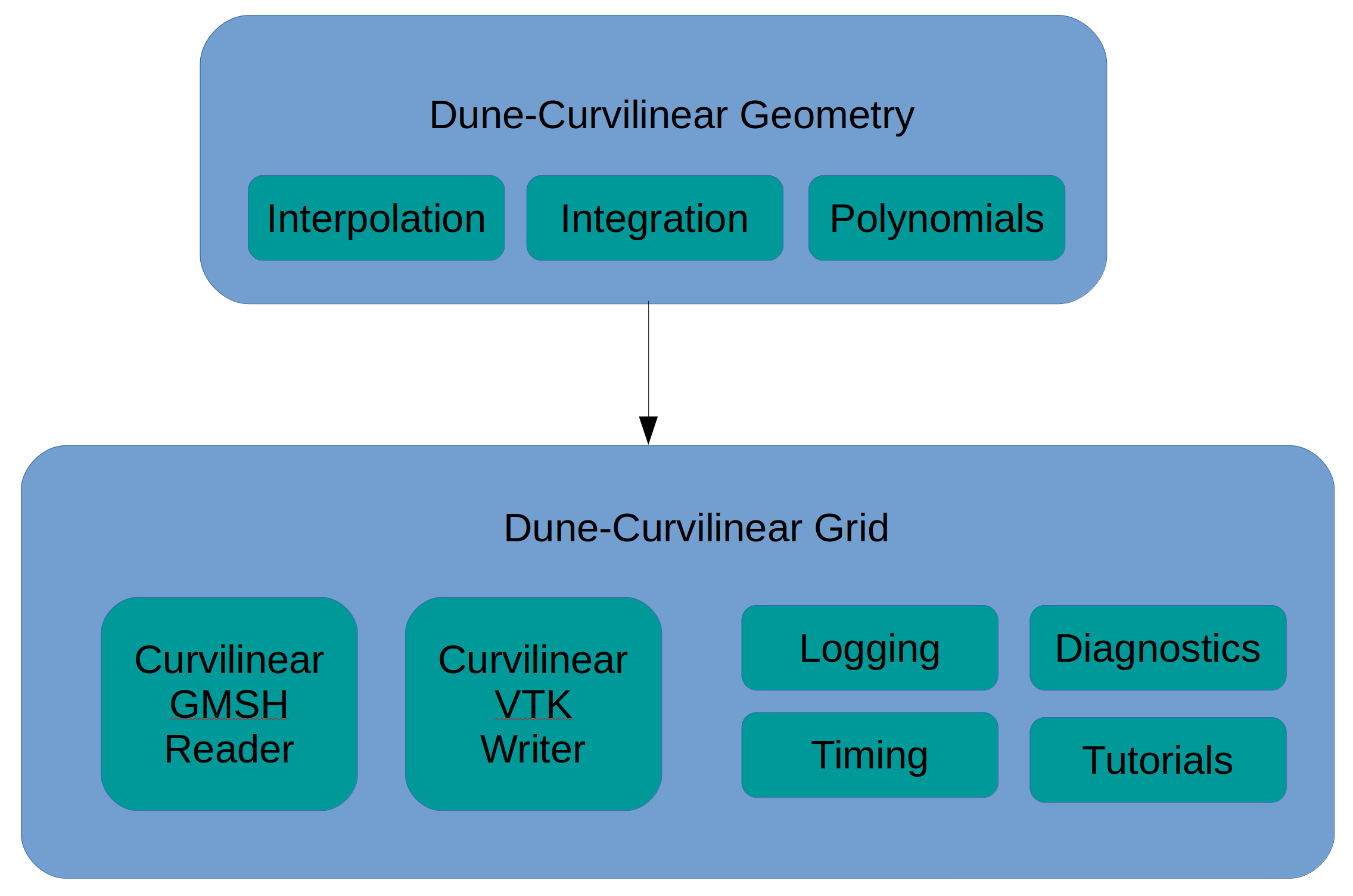
dune-curvilineargrid module manages the entire process of reading, manipulating, and writing of curvilinear geometries and associated fields (e.g. PDE solution). The former is accomplished by Curvilinear GMSH Reader (curvreader) class. curvreader is currently capable of reading curvilinear .msh files of orders 1 to 5, where 1 corresponds to linear meshes. curvreader is fully parallel and scalable for large parallel architectures. Each process only reads the necessary local part of the mesh, distributing the memory equally among all processes. It must be noted that earlier implementation of GMSH Reader in the dune-grid module suffered from serial reading of the mesh on the master process, which is no longer a bottleneck in our implementation. curvreader has the option to partition the mesh using ParMETIS during the reading procedure before reading the curvature vertices, further decreasing the file access time. curvreader also reads material elementary and boundary tags provided by gmsh. It extends the standard Grid Factory interface, providing tag information, as well as curvilinear order. The grid output is accomplished by Curvilinear VTK Writer (curvwriter) module, supporting VTK, VTU and PVTU file formats. curvwriter can either write the entire grid automatically, or write a set of individual entities, one at a time. When writing the entire grid, each element is supplied by fields denoting its rank, partition type (fig. 6) and physical tag, which can be used to visually inspect the parallel connectivity of the domain. The scalability of the grid assembly and visualization has been tested on parallel architectures containing from 12 to 128 cores. By the time of writing, the dune-curvilineargridhas been successfully run on several dozen different meshes, the largest being the 4.4 million element tetrahedral mesh fig. 7. The user has full flexibility to define the codimensions of the entities that will be written, the choice to write interior, domain, process boundaries and/or ghost elements, as well as the order of virtual refinement of curvilinear entities. The output mesh can be supplied with an arbitrary number of vector and scalar fields representing, for example, the solution(s) of a PDE. We have tested the visualization capabilities of dune-curvilineargrid using ParaView [1] and VisIt [7] end user software.
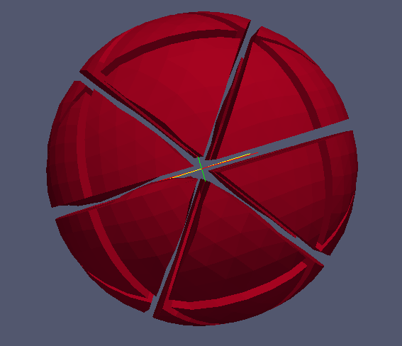
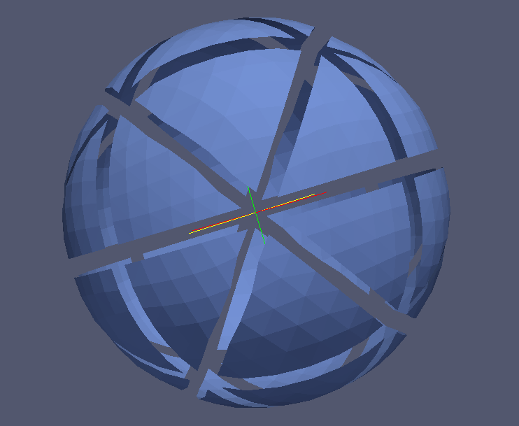
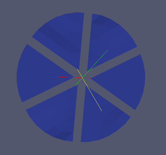
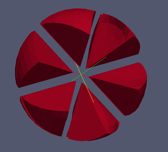
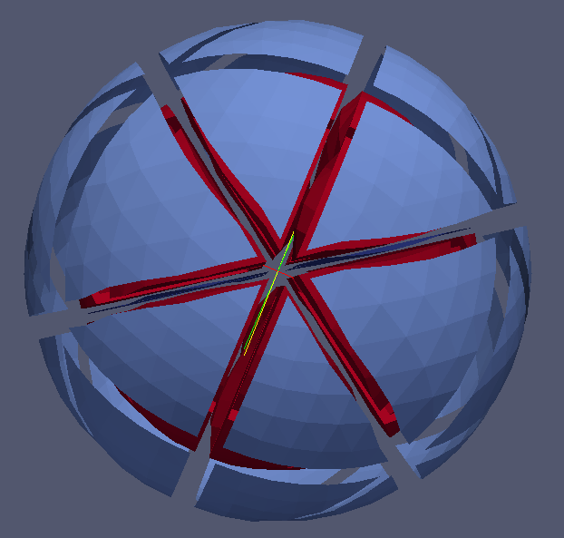
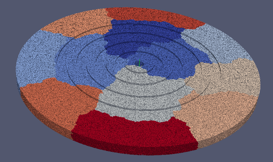
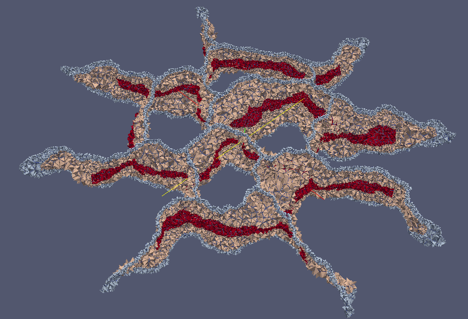
The core of dune-curvilineargrid provides the essential indexing and communication capabilities. The global and local indices are provided for entities of all codimensions. Interprocessor communication is performed via the DUNE standard DataHandle interface for provided Ghost elements entities of all codimensions. As an extension to the dune-grid interface, it is possible to directly address the core curvilinear geometry of each entity, as well as the associated physical tags. dune-curvilineargrid is also equipped with a set of useful utilities:
-
•
Timing mechanisms: parallel timing of separate parts of the code with statistics output over all processes
-
•
Logging mechanisms: real time logging of the current state of the code, as well as the current memory consumption on each core of a machine, allowing for the real-time diagnostics of memory bottlenecks of the code.
-
•
Nearest-neighbor communication - wrapper for the implementation of MPI_Neighbor_alltoall for vector communication with neighboring processes. This functionality is available as of the MPI-2 standard [18]
-
•
Global boundary container - interior/domain boundary all-to-all communication, useful for dense PDE solvers, such as the Boundary Integral method. [14]
-
•
Grid diagnostics - collects statistics on entity volumes, qualities and their distribution among processes
2 Theory
2.1 Lagrange Polynomial Interpolation
Below we present the theory of interpolation using Lagrange polynomials, applied to simplex geometries, This section is inspired by [15, 11, 4], and is a summary of well-known results. The goal of Lagrange interpolation is to construct a mapping from local coordinates of an entity to global coordinates of the domain. In its own local coordinates, the entity will be denoted as a reference element [3]. A simplex reference element of dimension is given by the following local coordinates:
| Label | Dimension | Coordinates |
|---|---|---|
| 0 | ||
| 1 | ||
| 2 | ||
| 3 |
Local simplex geometries can be parametrized using the local coordinate vector :
| Entity | Parametrization | Range |
|---|---|---|
| Edge | ||
| Triangle | and | |
| Tetrahedron | , and |
Interpolatory Vertices
In order to define the curvilinear geometry, a set of global coordinates , known as interpolatory vertices, is provided. By convention, the interpolatory vertices correspond to a sorted structured grid on a reference simplex, namely
where is the interpolation order of the entity. It is useful to construct a bijective map from a structured local grid to the provided global coordinates. It is the job of the meshing software to ensure that the global geometry of an entity does is not self-intersecting, non-singular, and that its curvature is optimized for PDE convergence [17]. In general, a non-uniform local interpolatory grid should be used in order to minimize the effect of Runge phenomenon [20]. It is not an issue for lower polynomial orders, and is the standard currently provided by the available meshing software, so we shall restrict our attention only to uniform interpolation grids. The number of interpolatory points on a uniform grid over the reference simplex is described by triangular/tetrahedral numbers table 3. These numbers are conveniently also the numbers describing the total number of polynomially-complete monomials up to a given order:
| Entity \Order | 1 | 2 | 3 | 4 | 5 | general |
|---|---|---|---|---|---|---|
| Edge | 2 | 3 | 4 | 5 | 6 | |
| Triangle | 3 | 6 | 10 | 15 | 21 | |
| Tetrahedron | 4 | 10 | 20 | 35 | 56 |
Interpolatory Polynomials
The number of interpolatory vertices given in table 3 exactly matches the total number of monomials necessary to construct a complete polynomial of order or less. It can be observed that the uniform simplex discretization exactly matches the binomial/trinomial simplex, also known as the Pascal’s triangle, commonly used to visualize the complete monomial basis. We define the function as the set of all monomials of dimension and order less than or equal to . The first few sets for 1D, 2D and 3D are as follows:
| Edge | Triangle | Tetrahedron |
|---|---|---|
| etc. | etc. | etc. |
The mapping is chosen to exactly fit all the interpolatory vertices . Since the numbers of interpolatory vertices and monomials is the same, the interpolatory vertices will have a unique associated complete polynomial basis. This is not the same for entities of other geometry types. For example, for hexahedra, the above numbers do not match. Therefore, one either has to use a structured local grid with incomplete polynomial order basis, or choose a more sophisticated local discretization. Volakis et al [24] adopt the former approach, interpolating a 9 node 2nd order rectangle with 4th order incomplete polynomial basis that has a convenient separable tensor product form.
One way to formulate the local-to-global coordinate mapping is
| (1) |
where are the fixed interpolatory vertices, and are the Lagrange polynomials, defined by their interpolatory property
| (2) |
for all local interpolatory vertices . The advantage of this formulation is that the Lagrange polynomials are independent of the interpolatory vertices , and thus can be pre-computed and reused for all entities of a given order. It remains to determine the exact form of Lagrange polynomials. We will present a short proof that eq. 3 holds
| (3) |
Here, is a vector of monomials as defined in table 4. Given a fixed dimension , eq. 3 should hold for all polynomial orders . Both sides of eq. 3 are polynomials of order at most , which means that they have at most free parameters. Therefore, to prove that eq. 3 holds in general, it is sufficient to show that it holds for different arguments. Thus, it is enough to show that it holds for all , which in turn is true due to eq. 2. Finally, we can combine all monomials and Lagrange polynomials into corresponding vectors
| (4) |
where , and find the Lagrange polynomial coefficients by solving the linear system
| (5) |
It is important to note that the resulting interpolated geometry in global coordinates is not completely defined by the shape of its boundary, as the entire volume of the geometry inside the entity undergoes this polynomial transformation.
Implementation for Simplices
In this section we discuss how to efficiently enumerate the simplex interpolatory points and to construct the reference simplex grid.
Let us define a simplex of integer side length , and place a set of points at unit intervals. This can be done by using nested loops
-
•
, for to
-
•
, for to , to
-
•
, for to , to , to
Then, each integer vertex corresponds exactly to the power of in the expansion of
where and are the binomial, trinomial and quatrinomial coefficients. The powers of the parameters given in the above expansion correspond to the complete monomial basis for a polynomial of order . The local coordinates of the uniform grid over the reference simplex can then be written as (see fig. 8)

After the monomials and the parametric interpolation points have been constructed, it remains to construct the interpolation matrix by evaluating the monomials at the interpolation points and to solve the linear system eq. 5, obtaining the Lagrange polynomials. This has been implemented both explicitly, calculating and hard-coding all the simplex Lagrange interpolatory polynomials, and implicitly, implementing symbolic polynomial arithmetic. The latter has the advantage of unrestricted polynomial order, as well as the freedom of further analytic manipulation using of symbolic arithmetic and explicit differential operators, but comes at the cost of slight computational overhead.
The optimization of Lagrange polynomial evaluation is of crucial importance, since they are typically evaluated a significant amount of times, especially during the integration and minimization procedures. Our implementation of Lagrange polynomials benefits from the following observations:
-
•
Each Lagrange polynomial of a given order uses the same monomial summands. It is thus of an advantage to evaluate all the Lagrange polynomials at the same time, first evaluating all the necessary monomials, and then re-using the evaluated monomials to compute the polynomials.
-
•
Along the same lines, evaluating all monomials of a given order at the same time is cheaper than evaluating them separately. Lower order monomials can be used to construct higher order monomials by doing a single multiplication per monomial.
2.2 Coordinate transformation
In order to calculate the coordinate transformation properties, one requires the knowledge of the local-to-global map and its first partial derivatives. Currently, dune-curvilineargeometry only provides Lagrange polynomials themselves as hard-coded expressions. Their derivatives are not yet available as hard-coded quantities, and thus are constructed by differentiating the symbolic polynomial map. This is, naturally, a little slower than having hard-coded derivatives. The advantage of analytical formulation is that the user can further apply algebraic and differential operators to the symbolic map to obtain, for example, a Hessian matrix of the transformation.
Local-to-Global map
Local-to-global map is computed numerically using hard-coded Lagrange polynomials when the order is below or equal to 5, and through analytic procedures otherwise.
Jacobian and Inverse Jacobian
The local-to-global mapping is represented by a vector of symbolic polynomials, further computing Jacobian matrix using exact partial differentiation provided by the polynomial class. This results in a matrix of polynomials, which can be evaluated for the desired local coordinates. The Jacobian inverse and the integration element are then computed numerically using the DUNE provided linear algebra routines, the matrix inverse and pseudo-determinant respectively (see section A.1).
Global-to-Local map For polynomial elements, global-to-local map is the inverse of a polynomial map. Given the matching world and entity dimension, the method searches for the exact coordinate local to the element, that corresponds to the provided coordinate. Further, this method is extended to elements with by converting it to an optimization problem
| (6) |
searching for the local coordinate closest to the inverse of the desired global coordinate in terms of distance in global coordinates.
While this problem is always uniquely solvable in linear case, in the curvilinear case it poses several additional challenges
-
•
The polynomial interpolatory map is strictly bijective inside the reference element, which must be ensured by the mesh generator. However, this need not be the case outside it. For example, is a bijective 1D local-to-global map for an edge defined on . However, the map is clearly non-invertible for all , and thus asking for a local coordinate corresponding to the global coordinate has no defined answer.
-
•
Curvilinear geometries have singularities, e.g. in the previous example. At these points the integration element is zero, which most simple iterative methods can not handle. It is expected that the meshing software provides curvilinear entities with non-singular geometries, since this would result in infinitesimal global volumes associated with finite local volumes, destabilizing optimization methods and integration routines. There is no restriction on the singularity being in the near vicinity of the element, which may be enough to significantly damage convergence.
-
•
For , the optimization problem given by eq. 6 is highly nonlinear. There may be multiple solutions, even uncountably many.
For obvious reasons we will not solve the problem directly, as searching for the roots of a system of polynomial equations in 2D and 3D is well-known to be a challenging task [6]. Instead, the problem is solved by a first order Gauss-Newton method [5], extending the implementation from dune-multilineargeometry.
Based on an exchange with the DUNE user community, we have realized that in order to satisfy all use cases we need to implement two distinct methods
-
•
Restrictive method, useful to those who want to find the element containing the global coordinate, as well as the local coordinate inside that element. If the provided global coordinate is inside the element, the method will return a success and a valid local coordinate. Otherwise, the method will return a fail and no coordinate at all, meaning that the global coordinate is not inside the element. This method also extends to lower dimension entities, finding the local coordinate within the element (!), which minimizes the distance to the provided global coordinate. Given a well-defined map (non-singular in the vicinity of the element), this method is guaranteed to converge.
-
•
Non-restrictive method, useful to those who wish to extrapolate the global-to-local map beyond the reference element. This method searches for the inverse (or the distance minimizer) over the entire local domain. This is a best effort method - due to the above mentioned difficulties, it is expected to fail to converge for some maps and global coordinates. In this case, an exception is thrown.
Below we outline the algorithm of the restrictive method:
We are still looking to improve this method. It correctly predicts the global coordinates being inside and outside the element for most of our tests, but fails to identify the boundary points inside the element for certain cases.
2.3 Integration
In this section we discuss the computation of scalar and vector integrals. Any global integral can be subdivided into elementary integrals, and then parametrized using the local elementary coordinates
where are the global coordinates, are local coordinates of element , an arbitrary function defined over the domain, and the function , associated with the change of coordinates, is called the integration element. In the remainder of the section we focus on elementary integrals, so we drop the element index .
In the original dune-geometry paradigm, the geometry class does not explicitly compute integrals, only the integration element. The user can compute the integral over the reference element by using a quadrature rule [2] provided in dune-geometry, or another external integration module. Any numerical integral, in particular the numerical quadrature, can written as a weighted sum
where the and are the quadrature (sampling) points and associated weights. The sampling points and weights are a property of the particular quadrature rule, and can be reused for all integrands over the reference element. Given a polynomial order , one can construct a finite numerical quadrature, which will be exact for polynomial functions of order and below, and thus well approximate integral over any function, that is well-approximated by a polynomial.
Numerical quadrature methods in practice are considerably faster than any other known method for geometry dimensions [22], but they also have disadvantages. Many smooth functions, for example, sharply peaked, nearly singular, or those given by fractional polynomial order are known to have very slow Taylor series convergence, and hence may require very high quadrature order to achieve the desired accuracy. Also, numerical quadratures for non-trivial domains (e.g. simplices) have so far only been calculated to moderate orders. For example, Zhang et al [31] present order 21 triangular quadrature. Finding a numerical quadrature reduces to finding polynomial roots, which is known to be a hard problem in more than 1 dimension due to progressively higher decimal precision necessary to distinguish the roots from one another. One way to overcome these difficulties is to transform the integration domain to a cuboid using a Duffy transform (for full derivation, see abstract A.2)
The advantage of the cuboid geometry is that a quadrature rule can be constructed from a tensor product of 1D quadratures, which are readily available at relatively high orders. Quadrature rules created in this way have more points per order than the optimal rules, created specifically for the desired (e.g. simplex) geometries. At the time of writing, dune-geometry provides 1D quadratures up to order 61 and specific 2D and 3D simplex quadratures up to order 13. We are aware of the existence of advanced methods to improve performance of quadrature integration, such as sparse grids [19], but they are beyond the scope of this paper.
The integration functionality in dune-curvilineargeometry addresses two additional problems:
-
•
Integrating polynomials of arbitrary order
-
•
Integrating smooth functions with no a priori knowledge of the optimal polynomial approximation order.
Symbolic Integration
dune-curvilineargeometry implements a symbolic polynomial class, which is stored as a sum of monomials of a given order. Integrals over monomials of any given order can be computed analytically section A.3, and so can the integral over any arbitrary polynomial, which is a sum of monomial integrals.
| Cuboid Integrals |
|
|||
|---|---|---|---|---|
| Simplex Integrals |
|
The dune-curvilineargeometry polynomial class provides the exact integration functionality.
Adaptive Integration
In its general form, a scalar integral over an element can be written as
In the case of matching element and space dimension, e.g. volume in 3D, or area in 2D, the integration element simplifies to . Even though the absolute value function is not polynomial, it can be observed that is not allowed to change sign inside the element, as that would result in self-intersection. The change of sign implies that the global geometry contains both "positive" and "negative" volume, which happens due to twisting the global coordinates inside out at the singular point . Also, the singular point should not be present within the element, as it leads to zero volumes in global coordinates. Modern curvilinear meshing tools take account of these constraints when constructing meshes. Thus, in the case of well-conditioned elements, it remains to evaluate the integration element it anywhere inside the element and discard the minus sign if it happens to be negative. Then, given a polynomial integrand , the integral can be computed exactly using the quadrature rule of appropriate order.
In the case of mismatching dimensions, e.g. area in 3D, or length in 2D and 3D, cannot be simplified. It is a square root a polynomial that itself is not a square of another. Such integrals, in general, do not possess a closed form solution and have to be evaluated numerically. To address this problem, dune-curvilineargeometry provides a recursive integrator class, which iteratively increases the quadrature order until the estimated integration error converges to a desired tolerance level. This method can consume several milliseconds for calculation of the surface area of near-singular geometries, but for well-conditioned geometries it converges much faster. The method accepts integrands in terms of functors overloading a skeleton class, and the dune-curvilineargeometry uses it internally to provide volumes and surfaces of curvilinear entities, only requiring the user to additionally specify the desired tolerance level.
In addition, the integrator class supports simultaneous integration of vector and matrix integrands via and , as well as . The motivation of this implementation is due to the fact that, frequently, the simultaneous evaluation of a vector or a matrix is considerably cheaper than the individual evaluation of each of its components. The method provides several matrix and vector convergence error estimates, such as 1 and 2-norm, which can be selected by user to adapt to the problem at hand.
According to [22], best results in low-dimensional numerical integration are achieved by the adaptive quadrature of high degree, whereas Monte-Carlo methods perform better for high-dimensional integrals. Using an external adaptive library, for example the GSL extension due to Steven G. Johnson (http://ab-initio.mit.edu/wiki/index.php/Cubature) could be of advantage. This library is based on Clenshaw-Curtis quadrature, which has the advantage of being hierarchical. This means that the computation of next quadrature order reuses all previously-computed quadrature points, decreasing the computational effort.
3 Reading Curvilinear Grid
From the outset the parallel implementation of the Curvilinear GMSH Reader is targeted at high parallel scalability. It loads the mesh evenly on all involved processes, avoiding master process bottlenecks. The algorithm to achieve this requires reading the mesh file several times on each process:
The implementation has an option to directly output the processed mesh into file set for debugging purposes.
4 Constructing Curvilinear Grid
The grid construction is called by the Grid Factory (see B.3) after all the vertices, elements and boundary segments have been inserted. The construction of the dune-curvilineargrid is in accordance with the following plan
4.1 Storage
The paradigm used in dune-curvilineargrid is to store all data corresponding to the grid in a single class, namely the CurvilinearGridStorage class. Entities of each codimension are stored in arrays indexed by the local entity index, which is contiguous and starts from 0 on all processes. Each entity stores its global index, geometry type and partition type. For the detailed explanation on the correct assignment of partition types to entities of each codimension, the user is referred to the corresponding section of DUNE grid usage manual, found on the website of the project. Elements and faces also store the associated material (physical) tag. Elements store the local index of all interpolatory vertices in the Sorted Cartesian order (see section A.4). The edges and faces do not store the interpolatory vertex indices, as it would be wasteful for higher curvilinear orders. Instead, each edge and face is stored as a subentity of an associated parent element - any of the elements containing it. Thus, each subentity stores the parent element local index, as well as the subentity index, by which the subentity is indexed within the reference element. Finally, each face stores its boundary type - Interior, Domain Boundary or Periodic Boundary, as well as the index of the 2nd parent element that shares it. By convention, the primary parent element must always be interior to the process storing the face. The secondary parent element may be either interior, or Ghost (fig. 11). The data associated with a Ghost element is stored on the neighboring process, but can be accessed from this process as part of interprocessor communication. In case of Domain Boundaries, there is no secondary parent. By convention, any attempts to access the secondary parent of a Domain Boundary result in an exception, as the user code must take the provided partition type into account when addressing neighboring entities.
dune-curvilineargrid contains several different local index sets, designed to uniquely index only the entities of a given subset. Namely, Domain Boundary segments, Interior Boundary segments, Process Boundaries, remaining Interior boundaries, as well as Ghost elements each have their own local index. dune-curvilineargrid provides maps between those indices and local indices of all entities of a given codimension. In addition, there is a unique index for grid corners, namely the interpolatory vertices that define the linear entities (fig. 9). This is necessary, because the DUNE facade class operates in terms of linear elements, and thus requires a contiguous index for the corners. Importantly, among all vertices only entity corners possess unique process boundary index, since, for all interprocessor communication purposes, the mesh can be assumed to be linear without loss of generality. Finally, a map from global to local index is provided for entities of all codimensions.

dune-curvilineargrid operates with two different types of GlobalIds, designed to uniquely identify the entity among all processes. First of all, it is a pre-requisite that all vertices have an associated global index, which is either re-used from the mesh file, or constructed in the beginning of the grid construction procedure. Before the global indices for other codimensions are generated, these entities are uniquely identified by the sorted set of global indices of the entity corners, which can be used in a map to determine if a given communicated entity is already present on the receiving process. Later, when entities of all codimensions possess global index, the GlobalId is simply a wrapper of the global index, such as to use minimal amount of resources necessary. It is the latter GlobalId that is made available for the user code at the end of construction procedure.
For the purposes of iterating over frequently used entity subsets, the corresponding local index subsets are provided for each codimension. Namely, subsets are provided for all entities of a given codimension, Interior entities, Process Boundary entities, Domain Boundary entities, Ghost entities, Interior + Domain Boundaries (called interior in DUNE), Interior + Domain Boundaries + Process Boundaries (called interior border in DUNE).
For communication purposes, all communicating entities need to store a vector of ranks of processes with which these entities are shared. For more details on communicating entities, see section 4.4.
4.2 Global index construction
In this section we briefly describe the algorithm used to construct the global indices for all codimensions. The challenge in computing the global indices comes from the fact that originally the processes are not aware of their neighbors. Due to the insertion of complete boundary segments by the grid factory, each process can readily identify all of its process boundaries as the faces that have only one containing element on the process and are not already marked as domain boundaries. The algorithm has four definite stages - determining the neighboring process for each process boundary, assigning (virtual) ownership of each shared entity to only one of the processes sharing it, enumerating the global index on processes owning the entities, and communicating the global index to all other processes containing each shared entity.
The algorithm starts by determining neighbor ranks of each Process Boundary () corner. Currently, each process communicates all process boundary corner global indices to all other processes. From the received global indices each process can deduce all other processes sharing each of its corners. Then, each process assigns provisional neighbor processes to edges and faces by considering the processes that share all entity corners. If two processes share all the corners of a given entity, it does not mean that they share the entity as well (fig. 10). The ambiguity is quite rare, because most entities are shared only by two processes, and since each process boundary entity must be shared by at least two processes, there is no need to check if the entity exists. Nevertheless, the grid must be able to handle the rare case of an entity being shared by more than two processes. In this case, the edge and face GlobalIds (see section 4.1) are communicated to all provisional neighboring processes. Each of the provisional neighbor processes then responds, whether or not each entity corner set corresponds to an entity. The ranks that are not confirmed to share the entities are then removed from the neighbor list.

For each edge and face, an owner is determined. The ownership strategy is flexible, as long as all processes agree. Currently, a shared entity is considered to be owned the process with the lowest rank among those sharing it. Each process owns all of its non-shared entities. The number of entities owned by each process is then communicated to all other processes.
Each process then locally enumerates the global index of all its entities. To begin with, each process computes the shift in global index due to the entities of each codimension enumerated by the processes with ranks lower than this process rank. All processes enumerate global indices consecutively, starting with 0 on rank 0 process. This constructs a global index individually for each codimension. A global index over all entities is also constructed, shifting the enumeration also by all the enumerated entities of higher codimension.
The enumerated global indices are then communicated among all processes sharing the entities. By analyzing entity neighbors, each process can compute how many global indices it needs to send to and receive from each other process, avoiding extra communication. At the end of this process, the global-to-local index map is filled on each process.
4.3 Ghost element construction
Ghost entities are the subentities of the element on the other side of the process boundary face, including the element itself. The process boundary entities are not considered Ghost entities. Thus, the Ghost entities are the internal/domain boundary entities of another process, borrowed by this process. Construction of Ghost entities involves communicating all the information associated with the entities to the neighboring processes, and then incorporating the Ghost entities into the grid on the receiving side (fig. 11).

Since for every face the neighboring process rank has already been determined in the previous section, and the global index is already known, it remains only to communicate the corresponding neighbor entities and correctly integrate them into the local grid. Firstly, one needs to communicate the properties of the structure to be communicated. Thus, for each interior element next to the the interpolation order is communicated, as well as the number of faces it shares with the receiving side. It is important to note that a Ghost element can have more than one face associated to it, and the receiving side does not know in advance that two or three of its faces are associated with the same Ghost element. This is also the reason it is not possible to know in advance how many ghosts will be received from a neighbor process. Afterwards, for each Ghost element the global index, physical tag, global indices of all codimension subentities and subentity indices of faces of the element are communicated. The corresponding Ghost elements are then added to the mesh, and it is determined which vertex coordinates are missing. The vertex coordinates are not communicated immediately, because the neighbor process may already have some of the global coordinates due to narrow mesh appendices. Thus, each process communicates the number of vertex coordinates missing from each of its neighbors, and then communicates the missing coordinates.
4.4 Communication interface construction
The communication paradigm of DUNE DataHandle interface is to communicate data between instances of the same entity on different processes. Depending on the communication protocol, only entities of specific structural types will communicate. We will slightly redefine the partition type classes in this section for compactness reasons. There are three different communicating partition types
-
•
- Process boundary entities, that is, process boundary faces and their subentities
-
•
- Interior entities, including the but excluding the entities.
-
•
- Ghost elements and their subentities, excluding


We consider all partition type pairs, for which the DataHandle communication is possible (fig. 12). Note that interior entities only communicate to Ghost and vice-versa, because Process Boundaries are Process Boundaries on both neighboring processes. However, Process Boundaries can communicate to Ghosts and vice-versa, because a process boundary can be a Ghost with respect to a third process at the triple point.
The DataHandle interface foresees four communication protocols. The table 6 presents the communication interfaces used by Dune, and explains how they translate to communication between entities of above specified partition types
| Interface | Direction | ||||||||
|---|---|---|---|---|---|---|---|---|---|
|
— | Y | N | N | N | N | N | ||
| InteriorBorder_All | Forward | Y | Y | Y | N | N | N | ||
| InteriorBorder_All | Backward | Y | N | N | Y | Y | N | ||
| All_All | — | Y | Y | Y | Y | Y | Y |
The aim of this part of the grid constructor is to generate/reuse unique index maps for the sets , and . Then, for every communicating entity, for every possible partition type pair, we require an array of ranks of the processes for which such communication is possible. Note that the map for the pair already exists, it is constructed in the very beginning of the grid construction procedure to enable global indices and Ghost elements. The algorithm is as follows:
5 Writing Curvilinear Grid
For the grid output, two hierarchic classes have been implemented - CurvilinearVTKWriter and CurvilinearVTKGridWriter. The former discretizes and accumulates entities and fields one-by-one and later writes them, and the latter uses the former to write the entities of the grid by iterating over them. The implementation of the CurvilinearVTKWriter is best understood by considering its features.
-
1.
nodeSet is a vector of global coordinates of interpolatory vertices of the entity in correct order A.4
-
2.
tagSet is a set of 3 scalar fields used for diagnostics, which typically accompany all written elements. Namely, they are the physical tag, the partition type, and the containing process rank in that very order.
-
3.
interpolate parameter determines how the virtual refinement of the entity is performed. If true, the regular grid of interpolatory points is re-used to subdivide the entity into smaller linear entities. If false, a new regular grid is constructed for this purpose, using the nDiscretizationPoint parameter to determine the number of desired discretization vertices per edge. If the interpolation vertices are used the latter parameter is discarded. Note that the associated fields are sampled over the vertices of the virtual refinement grid, and thus increasing the virtual refinement is useful for better visualizing the element curvature and/or finer field resolution. Note that increasing nDiscretizationPoint results in quadratic increase in both writing time and the resulting visualization file size, so the parameter must be used with care.
-
4.
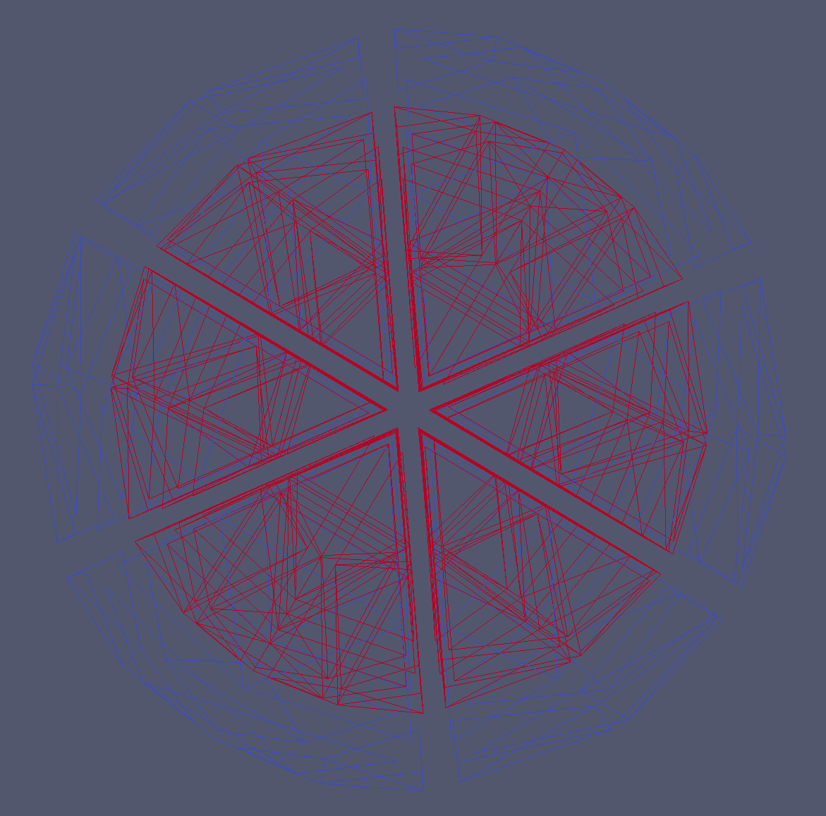
explode optional parameter shrinks all entities with respect to their mass-centers, allowing to better visualize the 3D structure of the grid. Default parameter is , which corresponds to no shrinking, and the maximum allowed parameter is
-
5.
magnify optional parameter expands all boundary surfaces with respect to the origin, allowing to better visualize the difference between boundary segments and element faces. By default there is no magnification
-
6.
writeCodim is a vector of 4 boolean variables, one for each entity codimension. This vector allows the user to control the specific codimensions of entities to be displayed. For example, it is possible to switch on only the edge wireframe of the mesh by providing
6 Tutorials
In order to start using the dune-curvilineargrid module we recommend to study the source code of the tutorials provided in curvilineargridhowto folder. The tutorials use progressively more complicated concepts, so it is recommended to address them in the indexed order.
6.1 Preliminaries - Creating Grid
All tutorials of dune-curvilineargrid reuse the simple auxiliary routine located in creategrid.hh. This routine contains paths to all meshes currently used in tutorials, allowing the user to select the desired mesh by providing its index. It then proceeds to initialize the logging mechanisms
These singleton classes are essential for dune-curvilineargrid, as they support the parallel logging of the grid reading, construction and writing process, as well as later statistics on performance of individual routines. They can also be used by the user to write user logging output and time user functions, comparing them to the grid construction time. The next step is initializing the Curvilinear Grid Factory
where the boolean variable determines whether the Ghost elements will be constructed and determines if the global element index from gmsh is going to be reused by the grid (recommended). Otherwise, the index is automatically generated (see Tutorial 6 for discussion). After the above prerequisites, the curvilinear gmsh reader is used to read the mesh file, partition it and write it to the provided grid factory.
The Curvilinear Grid Factory extends the interface of the standard dune grid factory, and therefore it will not work with other grids available in Dune. In order to achieve that, one must instead use the provided FactoryWrapper. This wrapper class adheres to the standard grid factory interface, and disregards any process tag or curvilinear information provided by the curvilinear gmsh reader.
Finally, the grid is constructed, providing the user with the associated pointer. We note that the user must delete the grid pointer after use.
6.2 Tutorial 1 - Getting started
This tutorial uses the above procedure to construct the dune-curvilineargrid by reading it from a gmsh file. This and all other tutorials can be run both in serial and in parallel. First we define the grid
where is the dimension of the grid, is the underlying real type, and the is a boolean variable determining if the curvilinear geometry caching is used (recommended). Currently, only 3D tetrahedral grids are available. Then, the curvilinear grid is created by the procedure described above. Finally, if we are interested in the time statistics for reading and construction of the grid, it can be obtained using the following command
6.3 Tutorial 2 - Traverse
This tutorial repeats the procedure from tutorial 1 to create the grid. It then iterates over the grid and extracts relevant information from the curvilinear entities. Currently, dune-curvilineargrid does not support refinement, so both leaf and level iterators will only iterate over the parent entities. As of DUNE 2.4 revision the range-based for iterators introduced in c++11 standard are the preferred way to perform grid iteration. The below example iterator will iterate over all entities of the grid of a given codimension
Now, we would like to extract some relevant information from the iterator
The and are standard in DUNE. provides a unique integer for each entity of a given codimension, over all processes. is the material tag associated with each entity, obtained from the mesh file. It can be used to relate to the material property of the entity, or to emphasize its belonging to a particular subdomain. In current dune-grid standard this information can only be obtained by through the reader and requires auxiliary constructions. denotes the integer polynomial interpolation order of the geometry of the entity. Currently, dune-curvilineargrid supports orders 1 to 5, the limiting factor being the curvilinear vertex indexing mapper in the reader. Finally, the gives the user direct access to the curvilinear geometry class of the entity, thus extending the interface provided by Dune::Grid::Geometry. For example, it can be used to obtain the set of interpolatory vertices of the geometry, or an analytic polynomial matrix representing its Jacobian.
6.4 Tutorial 3 - Visualization
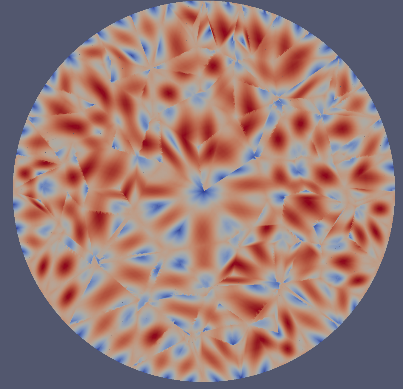
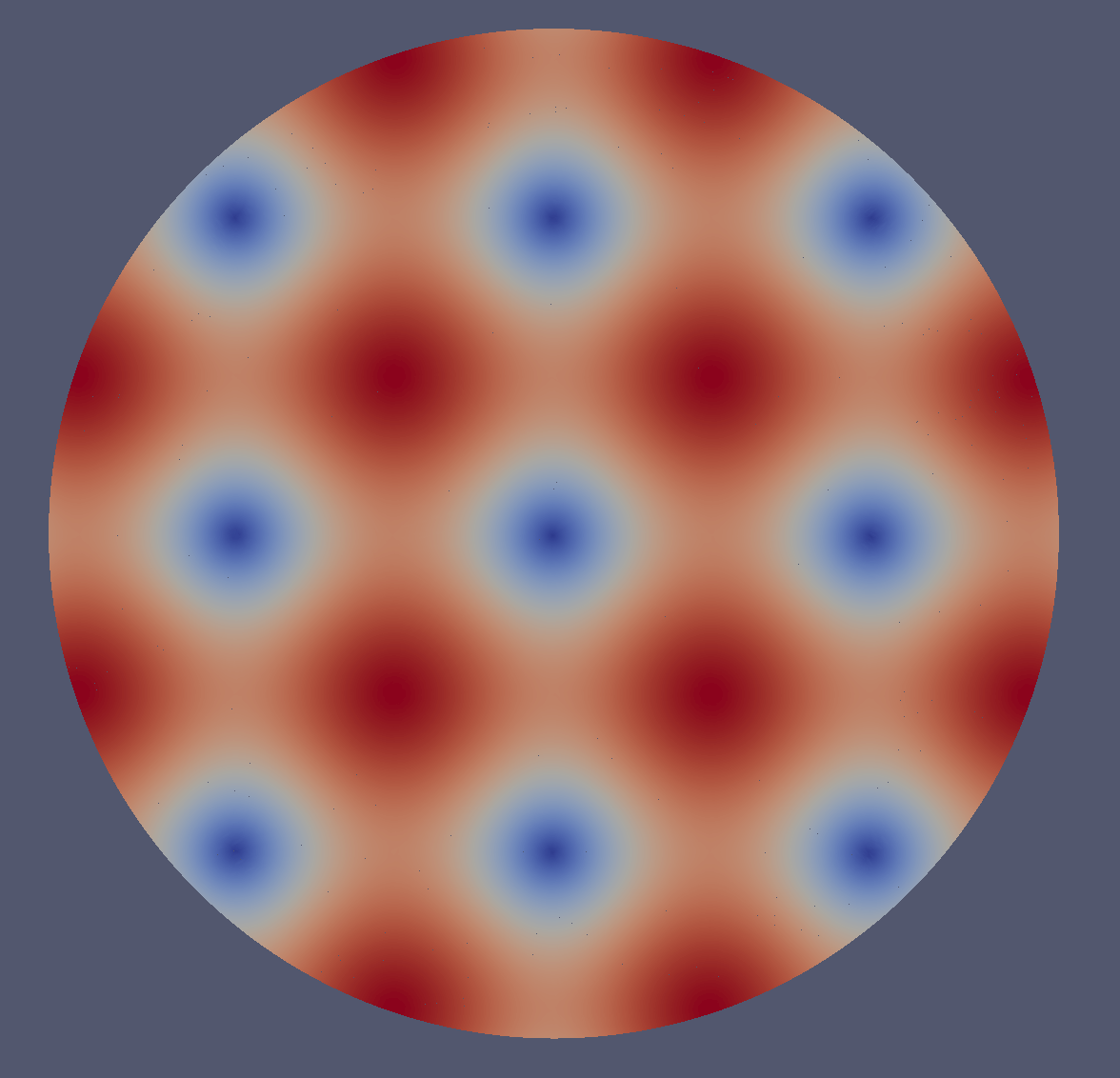
This tutorial demonstrates a simple way to output the curvilinear grid and associated vector fields (e.g. solutions of your PDE) to a PVTU file set using the CurvilinearVTKGridWriter class. The writer is able to output arbitrary number of user-defined fields. The fields can be scalar or vector, and can be associated either with elements or with boundary faces. The sampled fields must overload the Dune::VTKScalarFunction or Dune::VTKVectorFunction standard provided by dune-curvilineargrid, and thus adhere to the following interface:
We provide 6 examples:
-
•
Element index scalar in 3D, written over all elements of the grid;
-
•
Boundary segment index scalar in 2D, written over all boundary segments of the grid;
-
•
Local sinusoidal vector in 3D, written over all elements of the grid;
-
•
Local sinusoidal vector in 2D, written over all boundary segments of the grid;
-
•
Global sinusoidal vector in 3D, written over all elements of the grid;
-
•
Global sinusoidal vector in 2D, written over all boundary segments of the grid;
These examples illustrate the important difference between local and global coordinates. Local coordinates are unique for each element, so one shall observe unique field behavior for each element. Global coordinates on the other hand are the same for all elements, thus providing a single continuous sinusoid across the entire mesh. The local fields are associated with the orientation of the element in space, which is arbitrary up to the permutation of element corners. Thus, to correctly display local fields, one must consider the orientation of the element. This can be achieved by considering the global coordinates and/or global indices of the corner vertices of the element, and of the intersection faces in between two elements.
We start by constructing a curvilinear grid as previously demonstrated. We then proceed to initialize the writer, as well as fix its virtual refinement order to 15. We do this because we want to resolve the details of the sinusoid function to a very high precision, and because the mesh size is small. This operation is time-consuming, and, in general, the user should be aware of quadratic complexity of virtual refinement, and choose the refinement order that is necessary and sufficient. Should we choose to avoid specifying a fixed refinement order, the writer will calculate this order itself by considering the curvilinear order of the element. This works fine for most FEM applications, unless the basis order of the element is larger than its curvilinear order.
We proceed to stack the pointers to the above field functors into 4 arrays, distinguished by vector/scalar and 2D/3D fields. We have decided to use dynamic polymorphism to implement this functionality. While this may be less efficient than other implementations, it allows writing fields produced by different functors by the very same compact routine.
6.5 Tutorial 4 - Quadrature Integration Tutorials
The following two tutorials demonstrate the capability of dune-curvilineargrid to address mathematical and physical problems requiring integration of certain quantities over the grid domain.
Scalar Surface Integral - Gauss Law
In this example we verify Gauss law numerically by computing the surface integral of the electric field produced by a unit point charge across the domain boundary of the mesh enclosing that charge. The tutorial will demonstrate that changing the curvature of the domain boundary or the position of the charge inside the domain does not affect the result that is . More precisely, we compute the integral
where is the global coordinate, is the coordinate local to the surface finite element,
is the electric field of a unit charge located at , is the surface outer normal in global coordinates as a function of local coordinates and
is the generalized integration element due to conversion of the integral from global to local coordinates (see section A.1).
In order to use the dune-curvilineargeometry integration capabilities, the user must provide the integrand in the form of a functor class. The functor need not be overloaded, but must implement the operator
as a function of the coordinate local to the entity it is evaluated over, in this case, a 2D coordinate local to a face. The code then iterates over all domain boundaries of the grid, calculating integrals of the functor over each boundary segment and adding up the results. In order to integrate a functor, the QuadratureIntegrator class needs to be provided with the entity geometry, the functor to be integrated, the relative and absolute tolerances to be used for integration, as well as the norm type to be used for the case of multidimensional integration.
StatInfo is the return data type of the QuadratureIntegrator, which is a pair of the integral result and the quadrature order at which the desired relative accuracy was achieved. Note that the absolute accuracy ACCURACY_GOAL is used to determine if the integral is close enough to 0, as relative accuracy can not be used for this purpose due to division by 0.
Surface Vector Integral - Normal Integral
This test demonstrates the capability of QuadratureIntegrator to integrate vector quantities. It tests the well-known identity, stating that the integral over the unit outer normal over a closed bounded domain is 0.
| (7) |
The implementation of this test is almost identical to the Gauss integral test above. The only difference is that Dune::FieldVector is used as a functor output, and internally, instead of taking the dot product between the outer normal and the electric field, the normal itself is returned
6.6 Tutorial 5 - Communication via the DataHandle Interface
This tutorial, consisting of two parts, serves as a simple use-case of interprocessor communication through grid entities, which is achieved via the DataHandle interface.
In the first tutorial we explicitly select all entities of the grid that are supposed to communicate for each available communication protocol, and communicate a dummy constant. The goal is to confirm that all the expected entities were communicated over, and all others were not. In the second tutorial, the global index of each entity is sent according to the specified communication protocol, and compared to the global index on the receiving side. It is demonstrated that these indices match for each communicating pair, and an exception is thrown should this not be the case.
dune-curvilineargrid implements the DataHandle communicators in accordance to the standard DUNE interface, and its functionality does not exceed that envisioned by the standard interface. Since these tutorials are rather involved, and the standard mechanism is well-documented within the standard DUNE reference, the detailed explanation of these two tutorials is beyond the scope of this paper. For further information, the user is referred to the Dune Grid Howto documentation, found in www.dune-project.org
6.7 Tutorial 6 - Parallel Data Output
This tutorial demonstrates the use of a small utility ParallelDataWriter designed for sorted parallel output of vectors. It explores the benefits of using the global element index provided by the mesh, for debugging of parallel numerical codes. The tutorial demonstrate that a quantity sampled over all elements of the grid and sorted by the element global index is independent of the number of processes used. Thus, the user can directly compare the output file, generated by runs with varying process count.
Important Note: This tutorial only works if the mesh-provided global element index is re-used by the curvilinear gmsh reader (default). If this is not the case, the automatically generated global index will depend on the number of processes and destroy the above symmetry.
This tutorial samples the volume of the elements. However, the interface of the ParallelDataWriter extends to writing vectors of data for each element as well. One must first define the class
where IndexType and DataType are the data types of index and data arrays respectively. They can be any of the Plain Old Datatype (POD) classes, as long as their size is fixed over all processes for the communication purposes. One would then proceed to call the writer routine
where interiorElementNDof denotes the number of data entries per global index, and data stores all data entries for all global indices in a contiguous 1D vector.
6.8 Tutorial 7 - Global Boundary Communicator
This tutorial demonstrates the capabilities of dune-curvilineargrid to handle dense boundary communication problems, such as the Boundary Integral (BI) method. In the BI method, the global matrix or part of it correspond to pairwise coupling of every two faces on a given closed surface, providing a fully populated, i.e. dense, matrix. Each processor needs to obtain complete information of all faces on a given surface, collected over all processes.
In case isDomainBoundary is set to true, the BoundaryContainer does not require the last two parameters. Otherwise, one must specify the surface tag of the interior surface, as well as the volume tag of elements either on the interior or the exterior of the surface, all one or the other. The unit outer normal for each face of the surface is determined as the unit outer normal of the associated element. Thus, if one provides the volume tag of the elements on the outside of the interior surface, one will always receive the inner unit normal at a later stage, and will have to multiply all of them by -1 in order to obtain the unit outer normal. The BoundaryContainer does not contain the surfaces already located on this process, in order to save space.
In order to iterate over the BoundaryContainer, we implement the accompanying BoundaryIterator
The boundary iterator re-implements most of the functionality of the standard Dune iterator, such as geometry(), unitOuterNormal(), indexInInside(), geometryInInside(), as well as some additional functionality compactified into the same iterator to save on communication complexity, such as
The tutorial performs several tests of the communicated boundary, such as the normal integral from Tutorial 4, calculation of total number of edges, as well as the complementarity of the global index of boundary surfaces located on this process, and on the BoundaryContainer.
6.9 Tutorial 8 - Interior Boundary
The last tutorial extends the Gaussian integral tutorial to interior boundaries, performing integrals for a set of charges inside and outside of the boundary. This is a simple test to verify if the interior boundary of the mesh forms a closed surface.
7 Diagnostics tools
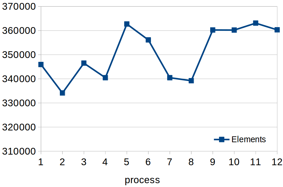
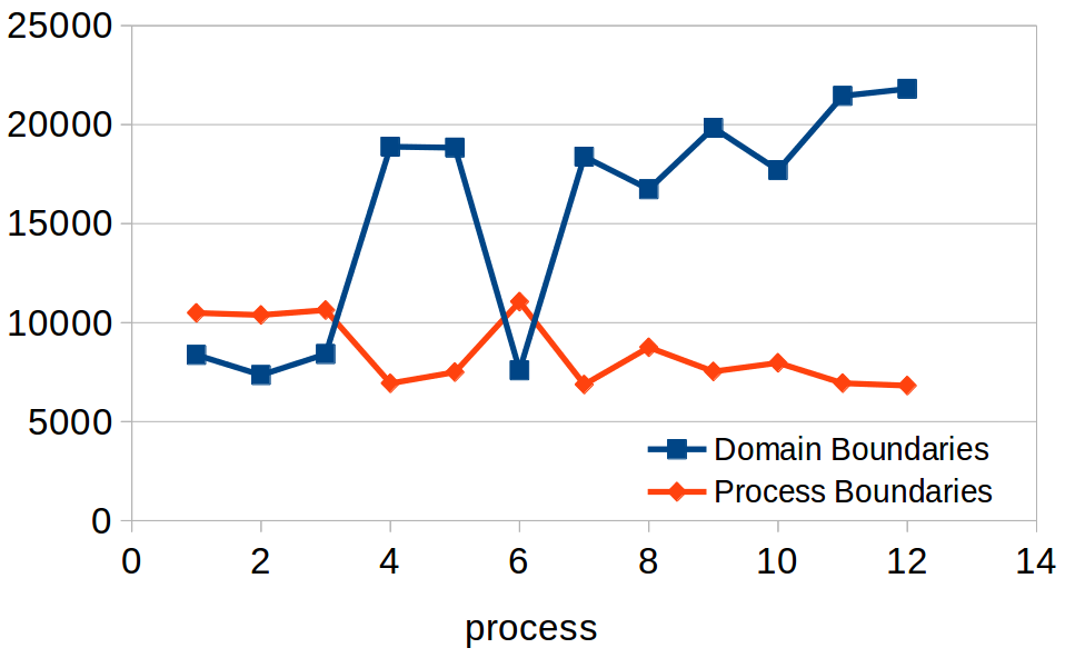
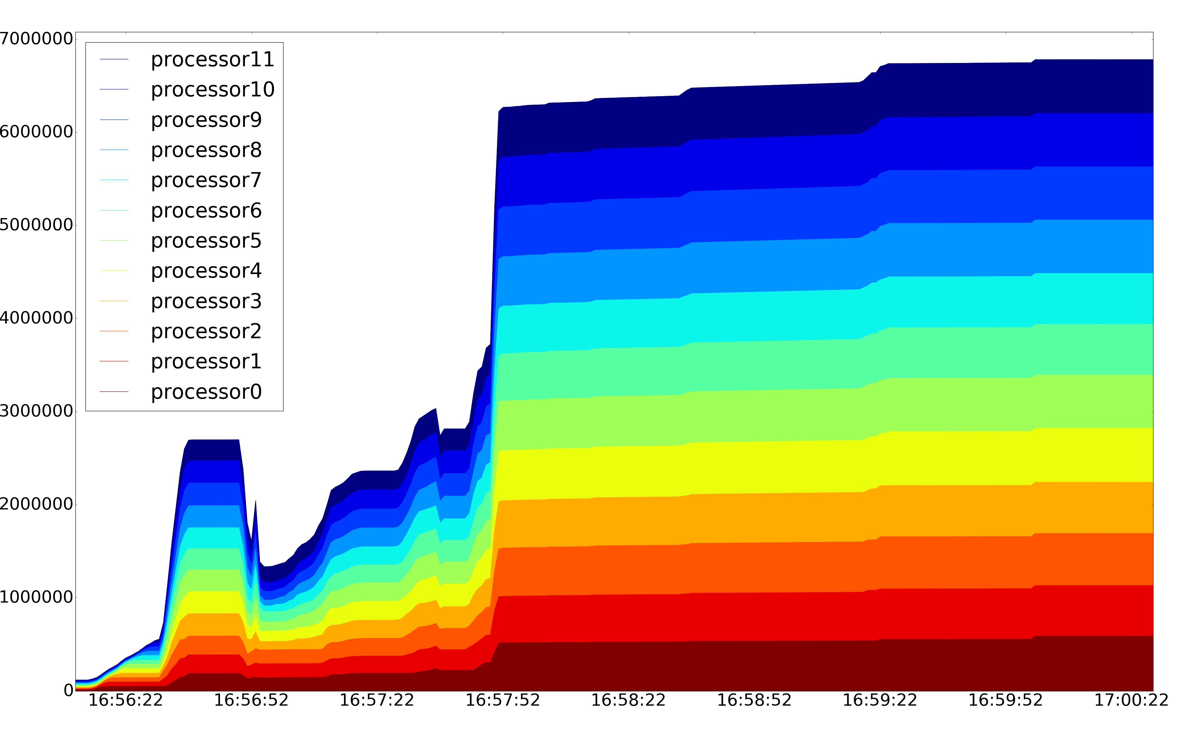
dune-curvilineargrid provides a diagnostics routine grid-diagnostics, designed to analyze the grid construction procedure. As an example, consider running the routine on a 12 core machine, using a 4.2 million element first order Bullseye mesh fig. 7. The diagnostics routine uses curvreader, gridconstructor and curvwriter to read the mesh, construct the grid, and write the resulting grid into a VTU/PVTU file set. Afterwards, it runs a number of statistics tests, evaluating the element distribution, average size and curvature. fig. 15 presents the distribution of elements, process boundaries and domain boundaries among the 12 processes. At any point in time, dune-curvilineargrid can report parallel timing, that is, minimal and maximal time taken by each process for each timed stage of the grid (table 7), using the LoggingTimer utility. This utility can also be used to time user code. Finally, the RealTimeLog utility, provided in dune-curvilineargrid, can be used to perform logging of the system memory real time by analyzing the corresponding system file. fig. 16 presents the plot of the memory logging file, as it is output after the mesh has been written to file. By comparing the plot with the timing, one can discern that a large amount of extra memory is taken by auxiliary structures during the grid reading and writing. The grid construction is finished at 16:56:51, and takes 3.6 GB of total memory.
| Min time [s] | Max time [s] | Action |
|---|---|---|
| 0.38411 | 0.384378 | CurvilinearGMSHReader: Skipping vertices |
| 3.86178 | 4.19604 | CurvilinearGMSHReader: Counting elements |
| 40.4335 | 40.7665 | CurvilinearGMSHReader: Reading and partitioning linear elements |
| 20.3694 | 23.1265 | CurvilinearGMSHReader: Reading complete element data |
| 11.071 | 13.6252 | CurvilinearGMSHReader: Reading boundary segment data |
| 0.758839 | 1.08354 | CurvilinearGMSHReader: Reading vertex coordinates |
| 3.50761 | 7.87511 | CurvilinearGMSHReader: Inserting entities into the factory |
| 8.29851 | 10.6347 | CurvilinearGridConstructor: Entity generation |
| 0.610859 | 2.95748 | CurvilinearGridConstructor: Global index generation |
| 0.228916 | 0.346936 | CurvilinearGridConstructor: Ghost element generation |
| 2.07785 | 2.81369 | CurvilinearGridConstructor: Index set generation |
| 0.300707 | 0.641833 | CurvilinearGridConstructor: Communication map generation |
| 0.0501765 | 0.685088 | CurvilinearGridConstructor: Communication of neighbor ranks |
| 151.23861 | 154.15874 | CurvilinearVTKWriter: Writing grid |
8 Testing
8.1 Curvilinear Geometry
test-polynomial. This test performs arithmetic operations, differentiation and integration of basic polynomials in 1D, 2D and 3D.
test-polynomialvector. This test generates random polynomial vectors in 3D and checks that basic vector calculus identities and hold.
test-quadratureintegration. This test performs recursive integration on a set of functions table 9 (given in section C.1) and reports the order at which the integral converges.
test-quadratureintegration-matrix. This test constructs random polynomial matrices, integrates them both recursively and analytically and compares the results.
test-lagrangeinterpolation. This test uses explicit polynomial maps given by functors and interpolates them using progressively higher order. It then evaluates the interpolated mapping, first for the interpolation points, then for a set of random points within the entity, and compares to the exact mapping. For the interpolatory points, the analytical and interpolated maps should always match due to the interpolatory property of Lagrange polynomials, whereas for all other points within the entity the maps would only match if the polynomial interpolation order is greater or equal to the polynomial order of the original map.
test-curvilineargeometry. This set of tests is performed for all 3 dimensions and for interpolation orders 1 to 5, first constructing the curvilinear geometries and cached geometries for a set of analytical functions table 10 in section C.1.
-
•
Test 1. Evaluate the global() mapping for all corners of the entity and compare to the analytical map.
-
•
Test 2. Evaluate the global() mapping for a random set of local coordinates within the entity, and compare the results to the analytical map. The test is omitted if the interpolation order is smaller than the order of the mapping.
-
•
Test 3. Evaluate the local() mapping for all global interpolation points of the entity and compare to the interpolatory reference grid. Also, check if all these points are reported to be inside the element. As described in section 2.2, the current local() method is imperfect:
-It fails to converge to a boundary point if the geometry has a zero derivative on the corner or on the whole boundary. This is the expected behavior for singular entities, thus such entities should be avoided at the meshing stage.
-It occasionally fails to correctly identify the point to be interior to the entity, if the point is close to the boundary.
-
•
Test 4. It is verified if for a set of random coordinates within the entity. It is also checked if all the sample points are reported to be inside the entity as they should be.
-
•
Test 5. It is verified that the global coordinates on the immediate exterior of the entity are correctly identified to be outside it, at the same time checking the functionality of the subentity normal functionality. For this, unit outer normals are constructed for a set of points across the boundary of the entity at regular intervals. The sample exterior points are then defined to be , where is the global coordinate of the boundary point, the normal at that point, and a small displacement, where is the length scale of all entities (see fig. 17).
- •
-
•
Test 7. The dot product surface integrals of vector basis functions are integrated over the reference geometry, and compared to the exact values. Integrands, mappings and exact results are given in table 12

8.2 Curvilinear Grid
At present, dune-curvilineargrid does not employ explicit testing procedures. The confidence in its accuracy is based on extensive testing of dune-curvilineargeometry, the accuracy of the provided tutorials, and the fact that our 3D FEM code based on the dune-curvilineargrid successfully reproduces reproduces standard benchmarks and experimental results. For discussion on future development of dune-curvilineargrid testing procedures, please refer to section 9
9 Further work
In this section we discuss the further work to be undertaken in the development of dune-curvilineargrid. table 8 presents a list of directions for further work in terms of functionality, performance and scalability. In addition, it is fully intended to implement an automatic dune-curvilineargrid testing procedure. The essential part of automatic testing is the integration of the standard dune-grid testing procedures, applicable to all grids that adhere to the facade class interface. From one side, dune-curvilineargrid extends the standard dune-grid interface, and it is not yet decided if it is best to extend the standard interface to include the additional curvilinear functionality, or if it is preferable to perform the additional curvilinear-only tests in a separate routine. From the other side, several tests for the current standard interface (for example, global-to-local mapping) are hard-wired to linear geometries and do not foresee the difference in expected behavior of such tests between linear and curvilinear grids. The integration of curvilinear standard functionality is an ongoing discussion within the DUNE community.
We would also like to elaborate on the improvement of scalability of dune-curvilineargrid assembly. Currently, the assembly of grid connectivity requires an all-to-all communication step to determine the neighboring processes for each shared vertex. An optimal algorithm to determine process neighbors should make use of the following observations:
-
•
Most interprocessor boundary vertices are shared by two processes only, all other cases are progressively more rare
-
•
If an interprocessor boundary vertex is shared between two processes, the surrounding vertices are likely to be shared by the same processes
Another convention responsible for the scalability of the construction process, albeit not as much as the all-to-all communication, is the shared entity ownership. Currently the shared entities are owned by the lowest rank containing them. This results in progressively higher workload of global index enumeration for lower rank processes. This paradigm can and should be replaced by a more balanced one. Another desired property is avoiding parallel communication in entity ownership determination. Thus, the ownership must be uniquely determined from the sharing process ranks and the shared entity corner global indices, and must result in the same ordering on all processes. An example of such convention is a operation between the entity corner global indices and the containing process ranks. This quantity is the same over all processes computing it, and is more or less random, resulting in a much better workload distribution than the lower rank convention. That said, the global index enumeration part is a algorithm, and thus is one of the faster parts of the constructor even without optimization.
| Functionality | 1D and 2D curvilinear simplex grids |
|---|---|
| Functionality | Arbitrary polynomial order curvilinear simplex meshes. Requires a generalized mapper from gmsh to Sorted Cartesian node indexing. |
| Functionality | Non-uniform polynomial order curvilinear meshes |
| Functionality | Additional geometry types (e.g. hexahedral, prismatic) |
| Functionality | Non-conformal curvilinear meshes (with hanging nodes) |
| Functionality | Global and local refinement of curvilinear grids, including adaptive refinement |
| Functionality | Mixed element grids |
| Functionality | Usage of gmsh partition tags to read pre-partitioned meshes |
| Functionality | Multi-constraint grid partition, for example, for simultaneous element and boundary segment load balancing |
| Functionality | Dynamic load balancing |
| Functionality | Front/Overlap partition types |
| Functionality | Identification and management of periodic boundaries directly from boundary tags |
| Performance | Symbolic polynomial vector and matrix classes that share pre-computed monomials |
| Performance | Adaptive quadrature (e.g. Clenshaw-Curtis), sparse grids [19] |
| Performance | Efficient location of the curvilinear element containing a given global coordinate (for example, via Octant Tree) |
| Performance | BoundaryContainer interior surface outer normal computation instead of communicating it |
| Performance | Optimization of curvwriter performance, memory footprint, and resulting file size |
| Scalability | Complete switch of dune-curvilineargrid to neighbor MPI communication |
| Scalability | Improved load balance of shared entity ownership during grid construction |
| Scalability | ParallelDataWriter scalability improvement using the MPI-3 parallel file output |
| Scalability | BoundaryContainer boundary surface communication using blocks that fit process memory |
Appendix A Proofs and Concepts
A.1 Integration Elements
When transforming an integral over an entity from global to local coordinates, the resulting integral acquires an additional prefactor called Integration Element
Edge(1D Local Coordinates):
For example, if global coordinates are 3D, then
Face(2D Local Coordinates):
For example, if global coordinates are 3D, then
Element(3D Local Coordinates):
It can be shown that the three above cases can all be rewritten as
where are the local coordinates, and is the Jacobian transformation defined as
which, for 3D global coordinates can be written as
Finally, in case where local and global dimension matches (e.g. edge in 1D, face in 2D, element in 3D), the Jacobian is a square matrix. If the geometry is strictly non-singular ( everywhere within the entity), the general expression for the integration element can be simplified to
A.2 Duffy Transform
The Duffy transform is a bijective map between the local coordinate of a hypercube and another entity, in our case, the reference simplex. One can use the Duffy transform to directly apply the hypercubic integration routines (e.g. tensor product quadrature rules) to simplex domains. Effectively, the Duffy transform claims that
giving explicit expressions for and .
We consider simplices of all dimensions up to 3:
1D: The reference hypercube and simplex are both an edge defined on , so they have exactly the same parameter.
2D: Here we map from reference triangle to reference square. We transform the integral of interest, namely
using a substitution , such that .
3D: Here we map from the reference tetrahedron to the reference cube. We transform the integral of interest, namely
using a substitution , such that .
A.3 Proof for polynomial summand integrals
Note that the series for beta-function can be written as
where is the binomial coefficient.
1D:
| (8) |
2D:
3D:
A.4 Convention for numbering interpolatory vertices
This section discusses the different conventions for numbering interpolatory vertices for Lagrange-based curvilinear entities. The convention used in Lagrange interpolation is placing of the interpolatory vertices on a regular grid over the entity, the number of vertices on each edge corresponding to the interpolatory order minus 1, i.e. 2 points to define linear edge, 3 to define quadratic and so on. The convention used in can be called Sorted Cartesian indexing, and is described by the following vertex enumeration algorithm.
Instead, the gmsh community uses the a recursive convention
-
1.
First number all corners, then all edges, then all faces, then the vertices interior to the element element
-
2.
Inside an edge, vertices are numbered sequentially from starting to finishing corner
-
3.
Inside a face, a new triangle is defined recursively from the outer-most interior vertices, with the same order as the original triangle
-
4.
Inside an element, a new element is defined recursively from the outer-most interior vertices, with the same order as the original triangle
-
5.
For a triangle, the order of edges is , , . (in 2D)
-
6.
For a tetrahedron, the order of edges is , , , , , .
-
7.
For a tetrahedron, the order of faces is , , , , including orientation
We are still looking for a nice algorithm to analytically map between both conventions for arbitrary order entities. For now, we hard code the GMSH to Dune map for simplex geometries up to order 5. The following table contains the Dune-notation vertex indices corresponding to ascending GMSH vertex index


Appendix B Interfaces
B.1 Polynomial Class
An arbitrary polynomial of order with parameters can be represented in its expanded form as
where is the power th dimension of th summand. For example, in 3D this can be written as
We define a Monomial class, which stores a constant multiplier and vector of powers .
A polynomial can be constructed either empty, from a single monomial or from another polynomial.
The below interface provides methods to perform basic algebraic operations with polynomials and scalars. The method is the scaled addition, equivalent to
We have implemented differentiation, integration and evaluation a polynomials. routine returns the partial derivative of a polynomial w.r.t. coordinate indexed by the parameter; routine evaluates the polynomial at the provided local coordinate; routine integrates the polynomial over the reference entity of the same dimension as the polynomial, returning a scalar. An integral of a monomial over the reference simplex has an analytical expression, see A.3
The following auxiliary methods can be used to provide additional information about a polynomial. routine returns the largest power among all monomials, that is, the sum of powers of that monomial; routine returns the largest absolute value prefactor over all monomials. routine converts the polynomial to a string for further text output
Also, caching is implemented via the routine. This method can be called after the polynomial will no longer be changed, but only evaluated. Pre-computing factorials and monomial powers accelerates further evaluation and analytical integration of the polynomial.
B.2 CurvilinearGeometryHelper
This section will discuss the interface of the CurvilinearGeometryHelper class. This is an auxiliary class of dune-curvilineargeometry, which provides functionality for addressing subentities of a uniform interpolatory grid, which are later used by dune-curvilineargeometry to address the subentity geometries.
Hard-coded number of curvilinear degrees of freedom as given in 2.1
Hard-coded map between a corner internal index and vertex internal index.
A procedure to extract corner indices from a vertex index set
A procedure to find the coordinate of a corner of a reference element based on its index.
A procedure to generate a set of integer coordinates for the uniform interpolatory simplex grid (see fig. 8)
A procedure to generate the local vertex set for a uniform interpolatory simplex grid (see fig. 8). Can re-use the already existing simplexGridEnumerate array for speedup
A procedure to extract the local interpolatory vertex grid of a subentity of a given entity. subentityCodim determines the codimension of the subentity, subentityIndex determines the internal index of the subentity within the parent entity.
B.3 Curvilinear Grid Factory
This section will discuss the information that needs to be provided in order to construct a curvilinear grid.
In the above constructor, withGhostElements determines if Ghost elements will be constructed, withGmshElementIndex determines if the global element index will be re-used from the gmsh file, or constructed from scratch, and mpihelper is the MPI Helper class provided by DUNE.
A vertex must be inserted using its global coordinate and global index. At the moment, dune-curvilineargrid construction procedure requires a priori knowledge of the vertex global index. All vertices belonging to each process must be inserted this way.
A curvilinear element must be inserted using its geometry type, interpolatory vertex local index STL vector, interpolatory order and physical tag. Currently, only 3D simplex elements are supported. All elements present on each process must be inserted. One must not insert elements not present on this process. The local index of an interpolatory vertex corresponds to the order the vertices were inserted into the grid. The order in which the vertex indices appear within the element is in accordance with the dune convention, discussed in section A.4. Currently the available interpolation orders are 1-5. The interpolation order must correspond to the number of interpolatory vertices. Currently, physical tag is an integer, corresponding to the material property of the entity or otherwise.
A curvilinear boundary segment must be inserted using its geometry type, interpolatory vertex local index vector, interpolatory order, physical tag, and boundary association. Currently, only 2D simplex boundary segments are supported. All boundary segments present on this process must be inserted. One must not insert boundary segments not present on this process. Domain boundary segments must always be present in the mesh file. If interior boundaries are present in the geometry, they are also inserted using this method, setting .
Same as the facade Grid Factory class, after the grid construction a pointer to that grid is returned. It is the duty of the user to delete the grid before the end of the program.
B.4 AllCommunicate
This section will discuss the templated the interface of our wrappers for MPI all-to-all communication and the nearest neighbor communication.
A wrapper for method allows arrays of arbitrary type , as long as its size is fixed and can be determined at compile-time (Plain Old Datatype, POD). This communication protocol is not scalable for very large architectures, since the number of communications performed by each process grows linearly with the process count. Its optimal use case is completely dense communication - every two processes exchange some information. The user needs to provide the input and output arrays, as well as the integer arrays denoting how many entries will be sent to and received from each process. Note that and need not be known a priori, but need to have sufficient memory reserved for the output to be written.
A more comfortable interface for the above communication uses STL vectors. The meaning of the arguments is the same, however, the memory is automatically reserved for the output vectors, so there is no need to compute the required memory a priori.
It is frequently the case that several processes need to communicate to several others, but most of the processes do not communicate to each other. Typically in finite difference or finite element implementations, each node communicates with the neighboring nodes only, and the communication per process stays constant with increasing process count. In this scenario, it is impractical to use all-to-all communication, and implementation of pairwise communication may be tedious. Starting from MPI-2 [18], the standard includes the nearest neighbor communication paradigm MPI_Neighbor_alltoallv, designed especially for this purpose. We provide wrappers for this function. In the following protocol, and concatenate all the data sent to and received from neighbor processes only. and specify the number of send-to-neighbors and receive-from-neighbors. and specify the ranks of all neighbor processes. Same as in the first protocol, all output variables need not be known a priori, but must have sufficient memory reserved.
We also present an STL vector version of the above, which automatically reserves memory for output vectors
Appendix C Explicit tests and solutions
C.1 Curvilinear Geometry Integral Tests
This section presents explicit polynomial maps, integrands and exact results for integrals used in dune-curvilineargeometry testing procedures (see section 8.1)
| Ref. Element | Function | Analytic result | Convergence order | Time to solution (ms) |
|---|---|---|---|---|
| 1D Simplex | 1 | 4 | 0.06 | |
| 1D Simplex | 0.5 | 4 | 0.06 | |
| 1D Simplex | 1.75 | 6 | 0.07 | |
| 1D Simplex | 0.666666667 | 28 | 0.07 | |
| 2D Simplex | 0.5 | 3 | 0.06 | |
| 2D Simplex | 0.666666667 | 3 | 0.07 | |
| 2D Simplex | 0.666666667 | 4 | 0.07 | |
| 2D Simplex | 0.016666667 | 5 | 0.08 | |
| 2D Simplex | 0.130899694 | 30 | 0.29 | |
| 2D Simplex | 1.785714286 | 9 | 0.07 | |
| 2D Simplex | 0.545584447 | 18 | 0.19 | |
| 2D Simplex | 0.353554 | 3 | 0.07 | |
| 3D Simplex | 1/6 | 3 | 0.07 | |
| 3D Simplex | 0.013297747 | 39 | 10.3 | |
| 3D Simplex | 0.0877136 | 13 | 0.36 |
| Ord | Dim | Scalar Basis Function |
|---|---|---|
| 0 | 1 | |
| 1 | 1 | |
| 2 | 1 | |
| 3 | 1 | |
| 4 | 1 | |
| 5 | 1 | |
| 0 | 2 | |
| 1 | 2 | |
| 2 | 2 | |
| 3 | 2 | |
| 4 | 2 | |
| 5 | 2 | |
| 0 | 3 | |
| 1 | 3 | |
| 2 | 3 | |
| 3 | 3 | |
| 4 | 3 | |
| 5 | 3 |
| Map | ||||||||
| 1 | ||||||||
| 1 | ||||||||
| 1 | ||||||||
| 1 | ||||||||
| 1 | ||||||||
| 1 | ||||||||
| 1 | ||||||||
| 1 | ||||||||
| 1 | ||||||||
| 2 | ||||||||
| 2 | ||||||||
| 2 | ||||||||
| 2 | ||||||||
| 2 | ||||||||
| 2 | ||||||||
| 3 | ||||||||
| 3 | ||||||||
| 3 |
| mydim | cdim | map | Normal | Integrand | Result |
|---|---|---|---|---|---|
| 1 | 2 | ||||
| 1 | 2 | ||||
| 1 | 2 | ||||
| 2 | 3 | ||||
| 2 | 3 | ||||
| 2 | 3 |
References
- joh [2005] Preface. In Charles D. Hansen and Chris R. Johnson, editors, Visualization Handbook. Butterworth-Heinemann, 2005. ISBN 978-0-12-387582-2. doi: http://dx.doi.org/10.1016/B978-012387582-2/50001-0. URL http://www.sciencedirect.com/science/article/pii/B9780123875822500010.
- Abramowitz and Stegun [1970] Milton Abramowitz and Irene A. Stegun. New York: Dover Publications, 1970.
- Bastian et al. [2008] P. Bastian, M. Blatt, A. Dedner, C. Engwer, R. Klöfkorn, M. Ohlberger, and O. Sander. A generic grid interface for parallel and adaptive scientific computing. part i: abstract framework. Computing, 82(2-3):103–119, 2008. ISSN 0010-485X. doi: 10.1007/s00607-008-0003-x. URL http://dx.doi.org/10.1007/s00607-008-0003-x.
- Berrut and Trefethen [2004] Jean-Paul Berrut and Lloyd N. Trefethen. Barycentric lagrange interpolation. SIAM Review, 46(3):501–517, 2004. doi: 10.1137/S0036144502417715. URL http://dx.doi.org/10.1137/S0036144502417715.
- Björck [1996] A. Björck. Numerical Methods for Least Squares Problems. Society for Industrial and Applied Mathematics, 1996. doi: 10.1137/1.9781611971484. URL http://epubs.siam.org/doi/abs/10.1137/1.9781611971484.
- Canny et al. [1989] J. F. Canny, E. Kaltofen, and L. Yagati. Solving systems of nonlinear polynomial equations faster. In Proceedings of the ACM-SIGSAM 1989 International Symposium on Symbolic and Algebraic Computation, ISSAC ’89, pages 121–128, New York, NY, USA, 1989. ACM. ISBN 0-89791-325-6. doi: 10.1145/74540.74556. URL http://doi.acm.org/10.1145/74540.74556.
- Childs et al. [2012] Hank Childs, Eric Brugger, Brad Whitlock, Jeremy Meredith, Sean Ahern, David Pugmire, Kathleen Biagas, Mark Miller, Cyrus Harrison, Gunther H. Weber, Hari Krishnan, Thomas Fogal, Allen Sanderson, Christoph Garth, E. Wes Bethel, David Camp, Oliver Rübel, Marc Durant, Jean M. Favre, and Paul Navrátil. VisIt: An End-User Tool For Visualizing and Analyzing Very Large Data. In High Performance Visualization–Enabling Extreme-Scale Scientific Insight, pages 357–372. Oct 2012.
- Ciarlet and Raviart [1972] P.G. Ciarlet and P.-A. Raviart. Interpolation theory over curved elements, with applications to finite element methods. Computer Methods in Applied Mechanics and Engineering, 1(2):217–249, Aug 1972. ISSN 0045-7825. doi: 10.1016/0045-7825(72)90006-0. URL http://dx.doi.org/10.1016/0045-7825(72)90006-0.
- Fahs [2011] H. Fahs. Improving accuracy of high-order discontinuous galerkin method for time-domain electromagnetics on curvilinear domains. International Journal of Computer Mathematics, 88(10):2124–2153, Jul 2011. ISSN 1029-0265. doi: 10.1080/00207160.2010.527960. URL http://dx.doi.org/10.1080/00207160.2010.527960.
- Geuzaine and Remacle [2009] C. Geuzaine and J. F. Remacle. Gmsh: a three-dimensional finite element mesh generator with built-in pre- and post-processing facilities. Int. J. Numer. Meth. Engng., 79(11):1309–1331, 2009.
- Ilic and Notaros [2003] M.M. Ilic and B.M. Notaros. Higher order hierarchical curved hexahedral vector finite elements for electromagnetic modeling. Microwave Theory and Techniques, IEEE Transactions on, 51(3):1026–1033, Mar 2003. ISSN 0018-9480. doi: 10.1109/TMTT.2003.808680.
- Jin [2014] Jian-Ming Jin. The finite element method in electromagnetics. John Wiley & Sons, 2014.
- Johnen et al. [2013] A. Johnen, J.-F. Remacle, and C. Geuzaine. Geometrical validity of curvilinear finite elements. Journal of Computational Physics, 233(0):359 – 372, 2013. ISSN 0021-9991. doi: http://dx.doi.org/10.1016/j.jcp.2012.08.051. URL http://www.sciencedirect.com/science/article/pii/S0021999112005219.
- Kern and Martin [2009] Andreas M. Kern and Olivier J. F. Martin. Modeling near-field properties of plasmonic nanoparticles: a surface integral approach. Plasmonics: Nanoimaging, Nanofabrication, and their Applications V, Aug 2009. doi: 10.1117/12.825833. URL http://dx.doi.org/10.1117/12.825833.
- Koshiba and Tsuji [2000] M. Koshiba and Y. Tsuji. Curvilinear hybrid edge/nodal elements with triangular shape for guided-wave problems. Lightwave Technology, Journal of, 18(5):737–743, May 2000. ISSN 0733-8724. doi: 10.1109/50.842091.
- Lasalle and Karypis [2013] Dominique Lasalle and George Karypis. Multi-threaded graph partitioning. In Proceedings of the 2013 IEEE 27th International Symposium on Parallel and Distributed Processing, IPDPS ’13, pages 225–236, Washington, DC, USA, 2013. IEEE Computer Society. ISBN 978-0-7695-4971-2. doi: 10.1109/IPDPS.2013.50. URL http://dx.doi.org/10.1109/IPDPS.2013.50.
- Lenoir [1986] M. Lenoir. Optimal isoparametric finite elements and error estimates for domains involving curved boundaries. SIAM Journal on Numerical Analysis, 23(3):pp. 562–580, 1986. ISSN 00361429. URL http://www.jstor.org/stable/2157524.
- MPI Forum [2016] MPI Forum. MPI: A Message-Passing Interface Standard. Version 3.1, June 21st 2016. available at: http://www.mpi-forum.org (June 2016).
- Petras [2000] Knut Petras. On the smolyak cubature error for analytic functions. Advances in Computational Mathematics, 12(1):71–93, 2000. ISSN 1019-7168. doi: 10.1023/A:1018904816230. URL http://dx.doi.org/10.1023/A%3A1018904816230.
- Runge [1901] Carl Runge. Über empirische Funktionen und die Interpolation zwischen äquidistanten Ordinaten. Zeitschrift für Mathematik und Physik, 46:224–243, 1901.
- Schloegel et al. [2002] Kirk Schloegel, George Karypis, and Vipin Kumar. Parallel static and dynamic multi-constraint graph partitioning. Concurrency and Computation: Practice and Experience, 14(3):219–240, 2002. ISSN 1532-0634. doi: 10.1002/cpe.605. URL http://dx.doi.org/10.1002/cpe.605.
- Schürer [2003] Rudolf Schürer. A comparison between (quasi-)monte carlo and cubature rule based methods for solving high-dimensional integration problems. Math. Comput. Simul., 62(3-6):509–517, March 2003. ISSN 0378-4754. doi: 10.1016/S0378-4754(02)00250-1. URL http://dx.doi.org/10.1016/S0378-4754(02)00250-1.
- Toulorge et al. [2013] Thomas Toulorge, Christophe Geuzaine, Jean-François Remacle, and Jonathan Lambrechts. Robust untangling of curvilinear meshes. Journal of Computational Physics, 254(0):8 – 26, 2013. ISSN 0021-9991. doi: http://dx.doi.org/10.1016/j.jcp.2013.07.022. URL http://www.sciencedirect.com/science/article/pii/S0021999113004956.
- Volakis et al. [2006] John L. Volakis, Kubilay Sertel, and Brian C. Usner. Frequency domain hybrid finite element methods for electromagnetics. Synthesis Lectures on Computational Electromagnetics, 1(1):1–156, 2006. doi: 10.2200/S00038ED1V01Y200606CEM010. URL http://dx.doi.org/10.2200/S00038ED1V01Y200606CEM010.
- Volakis et al. [1998] John Leonidas Volakis, Arindam Chatterjee, and Leo C. Kempel. Finite element method for electromagnetics. IEEE Press, 1998.
- Wang and Ida [1993] J.-S. Wang and N. Ida. Curvilinear and higher order ‘edge’ finite elements in electromagnetic field computation. Magnetics, IEEE Transactions on, 29(2):1491–1494, Mar 1993. ISSN 0018-9464. doi: 10.1109/20.250685.
- Wang et al. [2011] Jue Wang, S. Dosopoulos, D.A.O. Beig, Zhen Peng, and J.-F. Lee. High order parallel discontinuous galerkin time domain method with curvilinear element and continuously varying material properties for maxwell’s equations. In Antennas and Propagation (APSURSI), 2011 IEEE International Symposium on, pages 3261–3264, July 2011. doi: 10.1109/APS.2011.5997230.
- Wang et al. [2011-08-01T00:00:00] Mengyu Wang, Christian Engström, Kersten Schmidt, and Christian Hafner. On high-order fem applied to canonical scattering problems in plasmonics. Journal of Computational and Theoretical Nanoscience, 8(8):1564–1572, 2011-08-01T00:00:00. doi: doi:10.1166/jctn.2011.1851. URL http://www.ingentaconnect.com/content/asp/jctn/2011/00000008/00000008/art00030.
- Warburton [2012] Timothy. Warburton. GPU Accelerated Discontinuous Galerkin Methods. Workshop on Theory and Applications of Discontinuous Galerkin Methods, Mathematisches Forschungsinstitut Oberwolfach, 2012.
- Williams et al. [2009] Samuel Williams, Andrew Waterman, and David Patterson. Roofline: An insightful visual performance model for multicore architectures. Commun. ACM, 52(4):65–76, April 2009. ISSN 0001-0782. doi: 10.1145/1498765.1498785. URL http://doi.acm.org/10.1145/1498765.1498785.
- Zhang et al. [2008] Linbo Zhang, Tao Cui, and Hui Liu. A set of symmetric quadrature rules on triangles and tetrahedra. J. Comp. Math., 27, December 2008. URL http://www.global-sci.org/jcm/readabs.php?vol=27&no=1&page=89.