Decimetre-scaled spectrophotometric properties of the nucleus of comet 67P/Churyumov-Gerasimenko from OSIRIS observations
Abstract
We present the results of the photometric and spectrophotometric properties of the 67P/Churyumov-Gerasimenko nucleus derived with the OSIRIS instrument during the closest fly-by over the comet, which took place on 14th February 2015 at a distance of 6 km from the surface. Several images covering the 0–33∘ phase angle range were acquired, and the spatial resolution achieved was 11 cm/pxl. The flown-by region is located on the big lobe of the comet, near the borders of the Ash, Apis and Imhotep regions. Our analysis shows that this region features local heterogeneities at the decimetre scale. We observed difference of reflectance up to 40% between bright spots and sombre regions, and spectral slope variations up to 50%. The spectral reddening effect observed globally on the comet surface by Fornasier et al. (2015) is also observed locally on this region, but with a less steep behaviour. We note that numerous metre-sized boulders, which exhibit a smaller opposition effect, also appear spectrally redder than their surroundings. In this region, we found no evidence linking observed bright spots to exposed water-ice-rich material. We fitted our dataset using the Hapke 2008 photometric model. The region overflown is globally as dark as the whole nucleus (geometric albedo of 6.8%) and it has a high porosity value in the uppermost-layers (86%). These results of the photometric analysis at a decimetre scale indicate that the photometric properties of the flown-by region are similar to those previously found for the whole nucleus.
keywords:
comets: individual: 67P/Churyumov-Gerasimenko, space vehicles: ROSETTA, space vehicles: instruments: OSIRIS, methods: data analysis, techniques: image processing, techniques: photometry1 Introduction
The ROSETTA mission is the cornerstone mission of the European Space Agency devoted to the study of the minor bodies of the Solar System. Its primary objective is to perform an extensive study of the comet 67P/Churyumov-Gerasimenko (hereafter 67P/CG), of its nucleus as well as the contiguous cometary environment with the help of several instruments, including cameras, spectrometers, dust analysers and radio science experiments.
Previous space missions designed for comets exploration have helped building up an awesome trove of knowledge of those objects, yet the spacecrafts only performed flyby manoeuvres (we refer the reader to A’Hearn et al. (2005), A’Hearn et al. (2011), Barucci et al. (2011), and references therein). The Rosetta mission is the first one to escort a comet from 4 AU inbound, through its perihelion (1.24 AU in the case of 67P/CG) and back to 3 AU outbound, as well as the first one to have executed a flyby manoeuvre about 6 km above a cometary nucleus.
The Optical, Spectroscopic, and Infrared Remote Imaging System (OSIRIS) instrument is the scientific camera system on-board the ROSETTA orbiter.
This imaging system has allowed to perform extensive studies of the 67P/CG nucleus.
Beyond depicting a peculiar bi-lobate shape, OSIRIS has characterized a surface
exhibiting a complex morphology, including both fragile and consolidated rocky terrains,
dusty regions, depressions and pits, sometime active, and extensive layering
(Sierks
et al., 2015; Thomas
et al., 2015b; Vincent
et al., 2015; Massironi
et al., 2015).
Photometric and spectrophotometric properties of the 67P/CG comet were studied by
Fornasier
et al. (2015); La Forgia
et al. (2015); Oklay
et al. (2016); Lucchetti
et al. (2016); Pajola
et al. (2016).
In Fornasier
et al. (2015), the authors reported a globally red spectral
behaviour for the nucleus, consistent with that of primitive Solar System bodies
like Jupiter Trojans (Fornasier
et al., 2004, 2007)
and part of the trans-neptunian population (Fornasier
et al., 2009).
They found colour and albedo heterogeneities over the nucleus. Three kind of
terrains were identified on the basis of the spectral slope, those having a bluer
(i.e. a less steep spectral slope value) being associated to areas enriched in water-ice
content, and those having a higher spectral slope value were found predominantly
to correspond to dust rich regions.
The comet is dark: its geometric albedo reaches 6.5 % at 649 nm, and at a decametre scale, we observed local reflectance variations up to 25% (Fornasier et al., 2015). The VIRTIS spectrometer results indicate a global surface composition dominated by dehydrated and organic-rich refractory materials (Capaccioni et al., 2015). However, several local bright spots were identified in the OSIRIS images (Pommerol et al., 2015b; Fornasier et al., 2016; Barucci et al., ress; Oklay et al., 2016) and interpreted as exposures of water-ice. The presence of water-ice has been confirmed by the VIRTIS observations in the Hapi and Imhothep regions, and in some of the bright spots De Sanctis et al. (2015); Filacchione et al. (2016); Barucci et al. (ress).
In this work, we investigate the photometric and spectro-photometric properties
of the comet 67P/CG’s nucleus based on a dataset of images, taken by the OSIRIS
imaging system, with the best spatial resolution (11 cm/pxl) since the S/C had started
to escort the comet, and in which the phase angle ranges from 0∘ up to
33∘.
We sought thus to study the heterogeneity of the nucleus at the decimetre
scale and to constraint parameters modelling the surge of intensity of the
reflected light at low phase angles.
The following section presents the instrument and the observations in question, and the third one
summarizes the steps of data reduction and preparation.
In the fourth and fifth sections, we shall present the results of our spectrophotometric analyses examining,
first, the flown-by region as a whole, and then considering parts of this region.
After which we shall present the results of our photometric analysis in the sixth section.
We discuss the results of our analyses in the seventh section.
2 Observations
| NAC Filter | Wavelength | Bandwidth |
|---|---|---|
| [nm] | [nm] | |
| F15 | 269.3 | 53.6 |
| F16 | 360.0 | 51.1 |
| F84 | 480.7 | 74.9 |
| F83 | 535.7 | 62.4 |
| F82 | 649.2 | 84.5 |
| F27 | 701.2 | 22.1 |
| F88 | 743.7 | 64.1 |
| F51 | 805.3 | 40.5 |
| F41 | 882.1 | 65.9 |
| F61 | 931.9 | 34.9 |
| F71 | 989.3 | 38.2 |
The OSIRIS imaging system comprises two cameras: the Narrow-Angle Camera
(hereafter NAC) and the Wide-Angle Camera (hereafter WAC). The NAC has a
field-of-view of 2.35∘x2.35∘, it was designed to perform
observations of the nucleus with broad-band filters ranging from the near UV to
the near IR domains (240-1000 nm) at an angular resolution of 18.6 rad per
pixel. Those filters are optimized for the study of the nucleus’ mineralogy.
The WAC has a field-of-view of 11.6∘x12.1∘, and was designed
to perform observations of the dust and gaseous species in the coma in the same
wavelength domain (250-1000 nm) though with narrow-band filters at an
angular resolution of 101 rad per pixel.
Both cameras are equipped with the same detector system: a 2048x2048 pixels
array CCD with a pixel size of 13.5 m. For more detailed description of
the instrument, we refer the reader to Keller
et al. (2007).
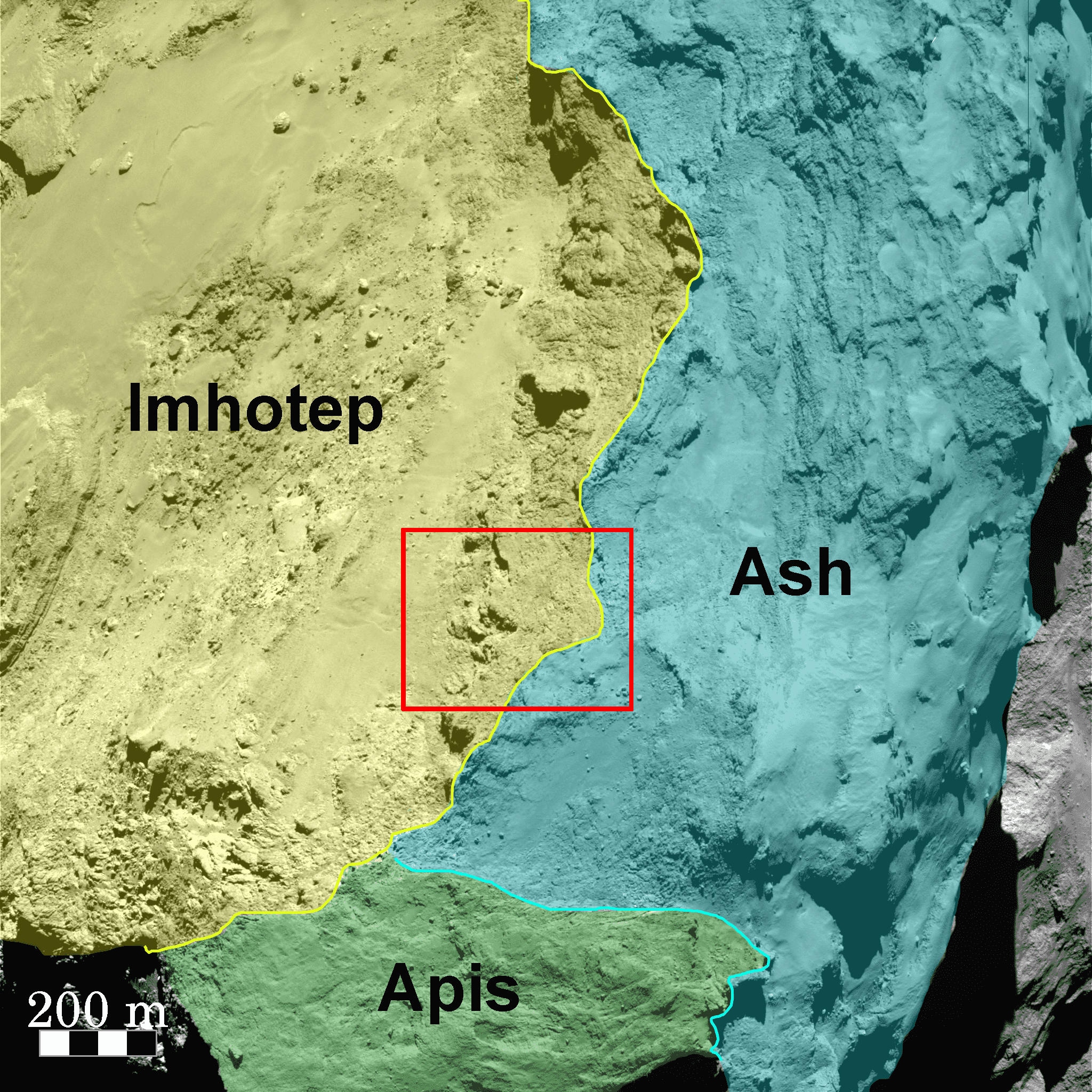
On the 14th of February 2015, the ROSETTA spacecraft flew over the
Imhotep region, and the closest approach took place close to the boundary between Ash,
Apis and Imhotep, as depicted in Fig. 1.
For detailed descriptions of the definition of the comet’s morphological and
structural regions, we refer the reader to Thomas
et al. (2015a)
and El-Maarry
et al. (2015).
Around the time of closest approach, the OSIRIS instrument took series of
observations using several filters with both NAC and WAC cameras. For the NAC,
those observations were performed using two sets of filters: 23 series of
observations with 3 filters (namely F82, F84 and F88), and 2 series of
observations with all the 11 NAC filters (see Tables 1, and
2).
The WAC took series of observations using only 2 filters (one centred at 375.6
nm, another at 631.6 nm). However, as multiple shutter errors plagued the
WAC during the flyby, we did not include those images in our
analysis.
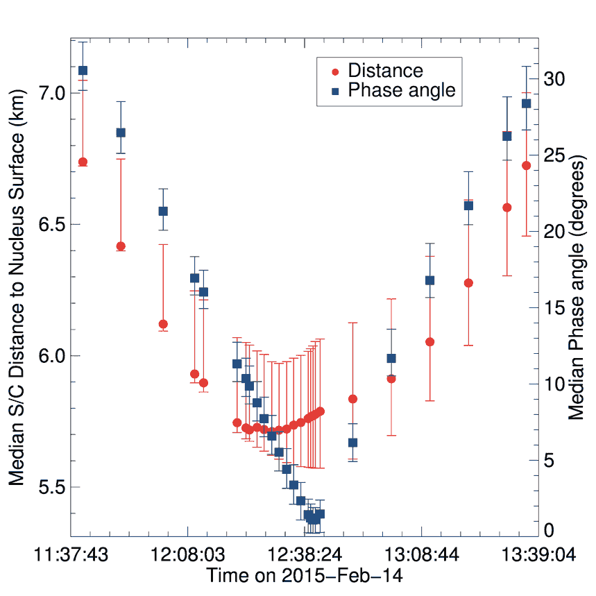
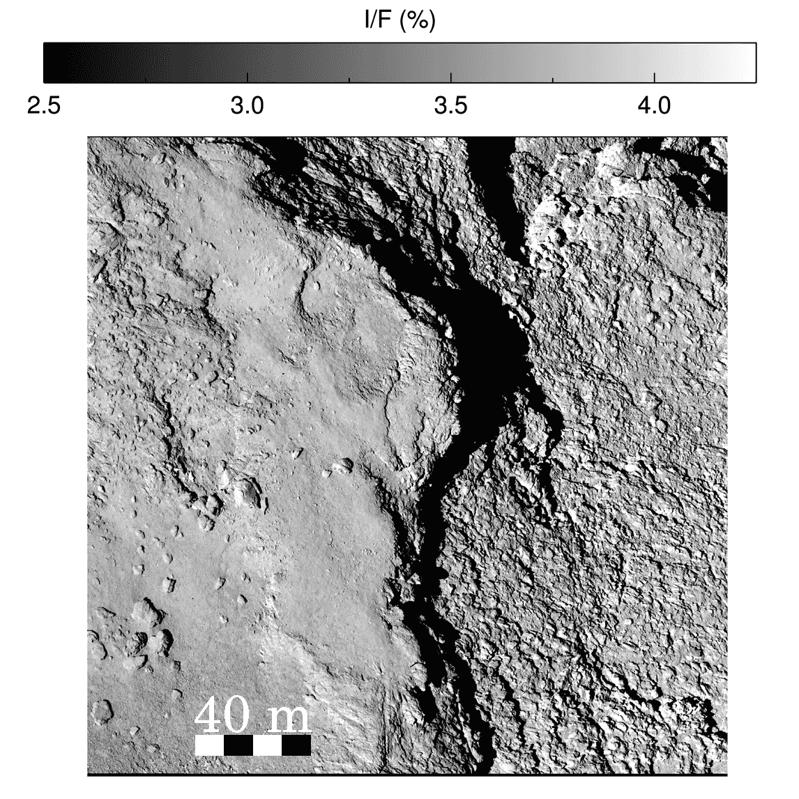
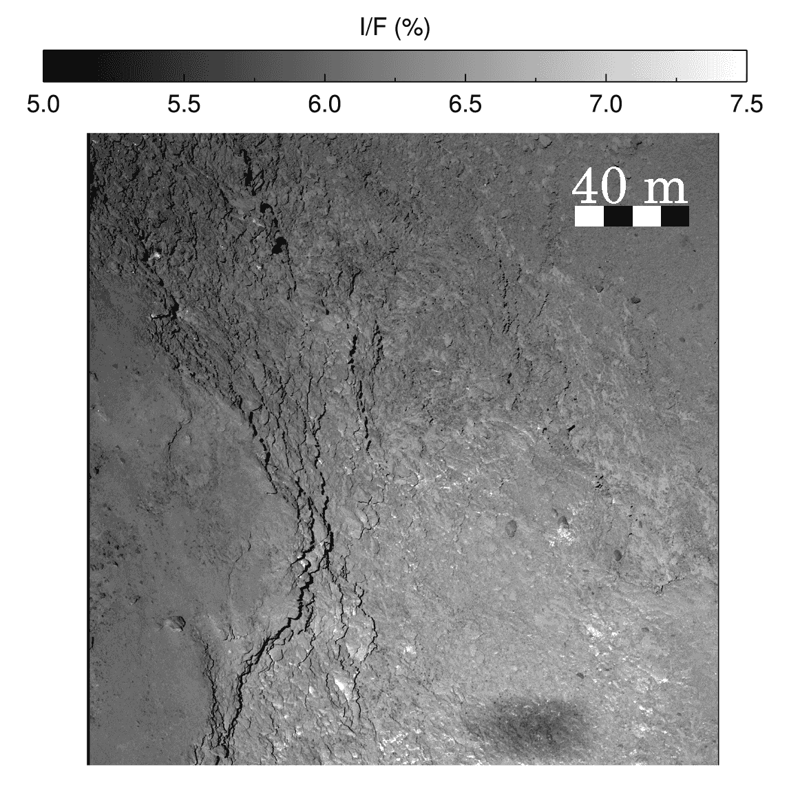
At that epoch, the comet was 2.31 AU away from the Sun and according to the trajectory and attitude reconstruction in the frame of the Cheops boulder (Preusker et al., 2015b), the median distance between the spacecraft and the part of the nucleus surface apparent in the NAC field-of-view varies between 5.711 km and 6.737 km. The minimum distance was attained at 12:39:54 (Fig. 2). The variations of the uncertainties displayed in this figure are due to the dispersion of the values as the camera’s field-of-view pans different parts of the flown-by region. The median phase angle in the frame of the CCD varies between and 30.5. The NAC field of view being 2.35∘x2.35∘ wide, the comet surface was observed with a decimetre resolution and at a phase angle of zero between 12:39:58 (UTC) and 12:42:25 (UTC), as confirmed by the presence of the penumbra of Rosetta in the corresponding images (see Fig. 4).
The region flown-by has been identified as a part of the boundary between the morphological regions Ash and Imhotep. A dedicated 3D model of the region has been generated from this dataset (Preusker et al., 2015a). In the Cheops frame, this region extends from to in longitude, from to in latitude, and from km to km in distance from the nucleus centre of mass.
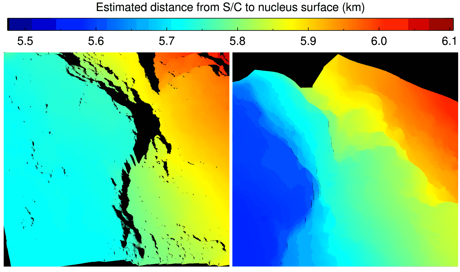
This analysed area is a transition region located between the fine deposits on the layered terrain unit (distance 5.75 km, in Fig. 3, left image) and the outcropping layered terrain unit (distance 5.7 km, in Fig. 3, right image) presented in Giacomini et al. (2016). The clear and unambiguous morphological limit which is here present, is the main reason for the distinction between the two separate geographical regions, i.e. the Ash region and the Imhotep depression (El-Maarry et al., 2015). As from Massironi et al. (2015) (see the extended data Fig. 2e) the studied area clearly shows the presence of metre to centimetre scale strata heads pointing towards Imhotep. Such strata are almost continuously present in the 500m steep cliff, demonstrating that the proposed layered structure of 67P/CG is not only detectable on a global scale, but also on the highest resolution images.
3 Data reduction
| Camera | Time | Filter | Phase Angle | S/C Distance to | Resolution |
|---|---|---|---|---|---|
| (UTC) | (∘) | Nucleus Surface (km) | (m/pxl) | ||
| NAC | 2015-02-14T11:40:54 | F82, F84, F88 | 30.5 1.4 | 6.73 0.05 | 0.126 0.001 |
| NAC | 2015-02-14T11:50:45 | F82, F84, F88 | 26.4 1.4 | 6.41 0.07 | 0.120 0.001 |
| NAC | 2015-02-14T12:01:44 | F82, F84, F88 | 21.3 1.2 | 6.12 0.08 | 0.115 0.001 |
| NAC | 2015-02-14T12:09:54 | F15, F16, F82, F83, | 16.9 1.1 | 5.93 0.08 | 0.111 0.001 |
| - | - | F84, F27, F88, F41, | - | - | - |
| - | - | F61, F71, F51 | - | - | - |
| NAC | 2015-02-14T12:12:12 | F82, F84, F88 | 16.0 1.1 | 5.89 0.08 | 0.111 0.001 |
| NAC | 2015-02-14T12:20:54 | F15, F16, F82, F83, | 11.3 1.1 | 5.74 0.08 | 0.108 0.001 |
| - | - | F84, F27, F88, F41, | - | - | - |
| - | - | F61, F71, F51 | - | - | - |
| NAC | 2015-02-14T12:23:12 | F82, F84, F88 | 10.3 1.0 | 5.72 0.08 | 0.107 0.001 |
| NAC | 2015-02-14T12:24:05 | F82, F84, F88 | 9.8 1.0 | 5.71 0.08 | 0.107 0.001 |
| NAC | 2015-02-14T12:26:05 | F82, F84, F88 | 8.7 1.0 | 5.72 0.08 | 0.107 0.001 |
| NAC | 2015-02-14T12:27:54 | F82, F84, F88 | 7.7 1.0 | 5.71 0.09 | 0.107 0.001 |
| NAC | 2015-02-14T12:29:54 | F82, F84, F88 | 6.6 0.9 | 5.71 0.09 | 0.107 0.001 |
| NAC | 2015-02-14T12:31:45 | F82, F84, F88 | 5.5 0.9 | 5.71 0.10 | 0.107 0.002 |
| NAC | 2015-02-14T12:33:45 | F82, F84, F88 | 4.4 0.8 | 5.72 0.11 | 0.107 0.002 |
| NAC | 2015-02-14T12:35:34 | F82, F84, F88 | 3.3 0.8 | 5.73 0.11 | 0.107 0.002 |
| NAC | 2015-02-14T12:37:25 | F82, F84, F88 | 2.3 0.7 | 5.74 0.12 | 0.108 0.002 |
| NAC | 2015-02-14T12:39:19 | F82, F84, F88 | 1.4 0.6 | 5.76 0.12 | 0.108 0.002 |
| NAC | 2015-02-14T12:39:58 | F82, F84, F88 | 1.2 0.5 | 5.76 0.12 | 0.108 0.002 |
| NAC | 2015-02-14T12:40:34 | F82, F84, F88 | 1.0 0.5 | 5.77 0.12 | 0.108 0.002 |
| NAC | 2015-02-14T12:41:11 | F82, F84 | 1.1 0.5 | 5.77 0.12 | 0.108 0.002 |
| NAC | 2015-02-14T12:42:25 | F82 | 1.4 0.6 | 5.78 0.12 | 0.108 0.002 |
| NAC | 2015-02-14T12:50:54 | F82, F84, F88 | 6.1 0.8 | 5.83 0.12 | 0.109 0.002 |
| NAC | 2015-02-14T13:00:54 | F82, F84, F88 | 11.6 1.3 | 5.91 0.11 | 0.111 0.002 |
| NAC | 2015-02-14T13:10:54 | F82, F84, F88 | 16.7 1.6 | 6.05 0.12 | 0.113 0.002 |
| NAC | 2015-02-14T13:20:54 | F82, F84, F88 | 21.6 1.6 | 6.27 0.13 | 0.118 0.002 |
| NAC | 2015-02-14T13:30:54 | F82, F84, F88 | 26.2 1.8 | 6.56 0.13 | 0.123 0.002 |
| NAC | 2015-02-14T13:35:54 | F82, F84, F88 | 28.3 1.9 | 6.72 0.12 | 0.126 0.002 |
The images used for this study were reduced using the OSIRIS standard pipeline
(OsiCalliope v.1.0.0.21) up to level 3B, following the data reduction steps
described in Küppers
et al. (2007), and Tubiana
et al. (2015).
Those steps include correction for bias, flat field and geometric distortion,
and absolute flux calibration (in ).
The last step of the calibration transforms the images in radiance factor (hereafter noted RADF). The radiance factor was notably defined in Hapke (1993), we computed it here according to the following formula:
| (1) |
where I is the observed scattered radiance, and F⊙ the incoming
solar irradiance at the heliocentric distance of the comet. The solar
irradiance F is wavelength dependent and it
was calculated at the central wavelength of each filter to be consistent
with the methodology applied to derive the absolute calibration factors.
For the spectrophotometric analysis we first coregistered the images of a given observing sequence using the images acquired with the F82 NAC filter (centred at 649.2nm) as reference. A python script was developed to perform the coregistration based on an adaptation of the python code described in Van Der Walt et al. (2014).
We then generated simulated images of the solar incidence, emission and phase angles used for the photometric correction of the data. A 3D shape model of the region flown-by (hereafter Digital Terrain Model, or DTM) was created following the same procedure described in Preusker et al. (2015b). This model was used alongside SPICE kernels (Acton, 1996) of the reconstructed trajectory of the spacecraft produced by the Rosetta flight dynamics team of ESA and the Optimised Astrophysical Simulator for Imaging Systems (hereafter OASIS) (Jorda et al., 2010; Hasselmann et al., 2016) to retrieve the illumination conditions of each facet of the shape model.
Those informations were employed to produce a photometric correction of the data. For the spectrophotometric analysis, we correct the images for the illuminations conditions by applying the Lommel-Seeliger disk law:
| (2) |
where and are respectively the cosine of the solar incidence (i) and emission (e) angles.
Three-colors images (or hereafter RGB) were generated from the observations with the NAC filters centred at 743.7 nm (R), 649.2 nm (G), and 480.7 nm (B). These images were simply co-registered, no photometric corrections were applied to them. The RGBs were produced with the so-called STIFF program (Bertin, 2011). Figures 4 and 4 present two of the generated color-stretched RGB from the presented dataset, in order to investigate colour heterogeneities over the surface.
The spectral slope was computed using the following formula:
| (3) |
where Ri is the radiance factor at a given wavelength. We choose to maintain the normalisation at 535.7 nm (F83 filter), even for sequences where we do not have direct measurements with the F83 filter, to be coherent with previous studies on the comet and literature data. Thus, for the 3 filters sequences, we estimated the 535.7 nm flux for each pixel through a linear regression of the data acquired between 480.7 nm and 649.2 nm.
4 Global analysis of the flown-by region
The global spectrophotometric and photometric properties of the nucleus but also the surroundings of the flown-by region have been previously investigated by Fornasier et al. (2015) (see Figs. 9, 13, and 14) on the first resolved images of the comet acquired on July-August 2014, at 3.6 AU of heliocentric distance. The surroundings of the flown-by region were classed as belonging to the group of terrains with the highest spectral slope (i.e. the reddest) and, in the 882.1-535.7nm range, they were observed to have a spectral slope value > 14 %/(100nm) at phase angle 1.3∘, and > 18%/(100nm) at phase angle 50∘. The reader is referred to Figs. 14 and 9 in the aforementioned article for more details.
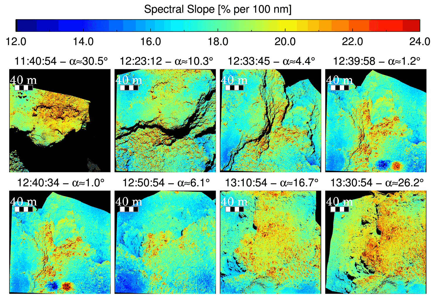
Fig. 4 depicts the RGB colours, reflectance and spectral slope maps of areas observed at 12:20:54 and 12:39:58. The surface clearly shows local reflectance and colour/spectral slope values variations, with the presence of several bright spots, sombre boulders and some striae, confirming that the surface is heterogeneous at several scales. Brightness variations in the comet’s surface at centimetre and millimetre scale were reported by the CIVA camera on-board the Philae lander (Bibring et al., 2015), which observed a surface globally dominated by dark conglomerate, likely made of organics, with the presence of brighter spots that may be linked to mineral grains or pointing to ice-rich material. Heterogeneities, reported by Fornasier et al. (2015), were observed at a larger scale (> 2 m/pxl).
From the 14th February images we find a median reflectance of 6.15
0.07% (cf. Fig. 4) in the F82 filter image taken at 12:39:58. The sombre
boulders show a reflectance 10% lower than the average value while
the brightest regions show a reflectance about 20% higher. However, in this
flown-by region, we do not see strong variations (i.e. a factor 2 or higher) in
reflectance as observed for bright spots and ice rich regions on different areas
of the nucleus
(Pommerol
et al., 2015b; Barucci et
al., ress; Oklay
et al., 2016; Fornasier et
al., 2016).
The most remarkable changes are observed in the images taken when the phase angle
is minimal, such as in Fig. 4.
In particular, we notice several boulders, metre-sized and sub-metre-sized, located on both
sides of the region, whose reflectance is lower than that of their surroundings at small phase
angle observations. We determined that the phase functions of those boulders are different from
that of observed bright spots, or even the immediate surroundings of such features.
This particular result is discussed in the next section alongside the photometric analysis of
the entire region (cf. Fig. 13 and table 5).
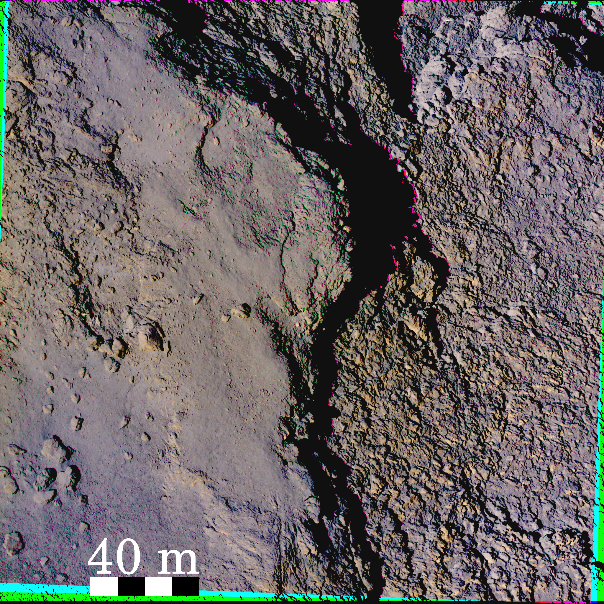

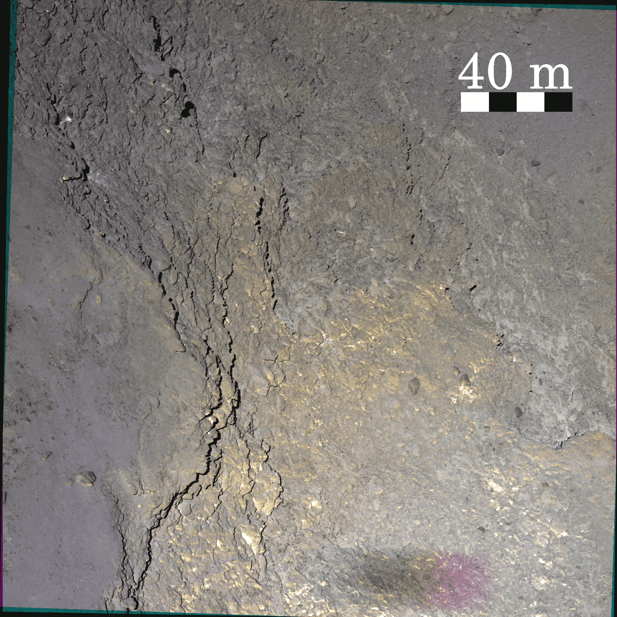

The RGB images (see figs. 4 and 4) indicate redder colours along the cliff in Fig. 4, and along the cliff, terraces, and outcrops in Fig. 4. In this image, the green to red artefact in the bottom is simply the shadow projected by the Rosetta spacecraft. Similarly, the receding of the projected shadows and the motion of the S/C also left artefacts in the RGB. Such elements on surface of the nucleus were not further considered.
In those colour-stretched RGBs, we note that most of the previously spotted bright patches and
striae of surface appear to be located where the nucleus surface looks redder. This is confirmed
by the spectral slope mappings (in the 743-535 nm range, Figs. 4
and 4), where the aforementioned
red features display indeed a strong spectral slope (above 21%/100nm). Spectral slopes values
are found to vary between 15 and 23 %/(100nm) at phase angle 1∘ (UTC:
12:39:58, cf. Fig. 10), confirming that the flown-by region
is one of the redder of the comet’s surface.
The spectral slope mappings evolution computed at different epochs of the flyby
is represented in Fig. 10 and the corresponding phase
reddening effect is discussed in section 5.1 and summarised
by Fig. 11.
We investigated the spectrophotometric properties of the surface on several relatively smooth areas visible on multiple sequences and on both morphological regions, and where no boulders are discernible at the decimetre scale. We considered the observations related to the 12:20:54 and 12:39:58 sequences. The integrated radiance factor inside boxes of 15x15 pixels (i.e. about 1.5x1.5m2 on the nucleus) is presented in Fig. 5. We note that, at every wavelength, the variations of the measured relative reflectances are, in average, of 3.52.1%. Furthermore, in the 743-535.5nm range, the median spectral slope of those measurements is found to be equal to (17.71.0)%/100nm. Hence, the smooth terrains investigated over the two different morphological regions were not found to be distinctly different.
We also note an increase of the flux in the 700-750 nm region, as already seen in Fornasier et al. (2015) analysis. These feature is not related to the nucleus surface properties but it has been linked to cometary activity and attributed to H2O+ and/or NH2 emission in the very inner coma (Fornasier et al., 2015). As our observations are mostly carried out in 3 filters, including the one centred to 743 nm, we need to estimate the cometary emission effects in the spectral slope value evaluated in the 743–535 nm range compared to the one evaluated in the 882–535 nm wavelength range, and used in the literature for the 67P/CG comet (La Forgia et al., 2015; Fornasier et al., 2015; Oklay et al., 2016; Pajola et al., 2016). We thus computed the spectral slopes for those investigated terrains, in both those wavelength ranges, for the observations acquired at 12:09:54 and 12:20:54, where the full set of NAC filters is available. We found that the spectral slopes computed in the 743–535 nm range are about 24% higher that those computed in the 882–535 nm range, thus indicating an important contribution of the cometary emission. The different spectral wavelength range used and the cometary emission contribution in the 743-535 nm spectral slope must be taken into account when comparing spectral slopes values reported in the literature.
5 Reflectance and spectral behaviour of local features
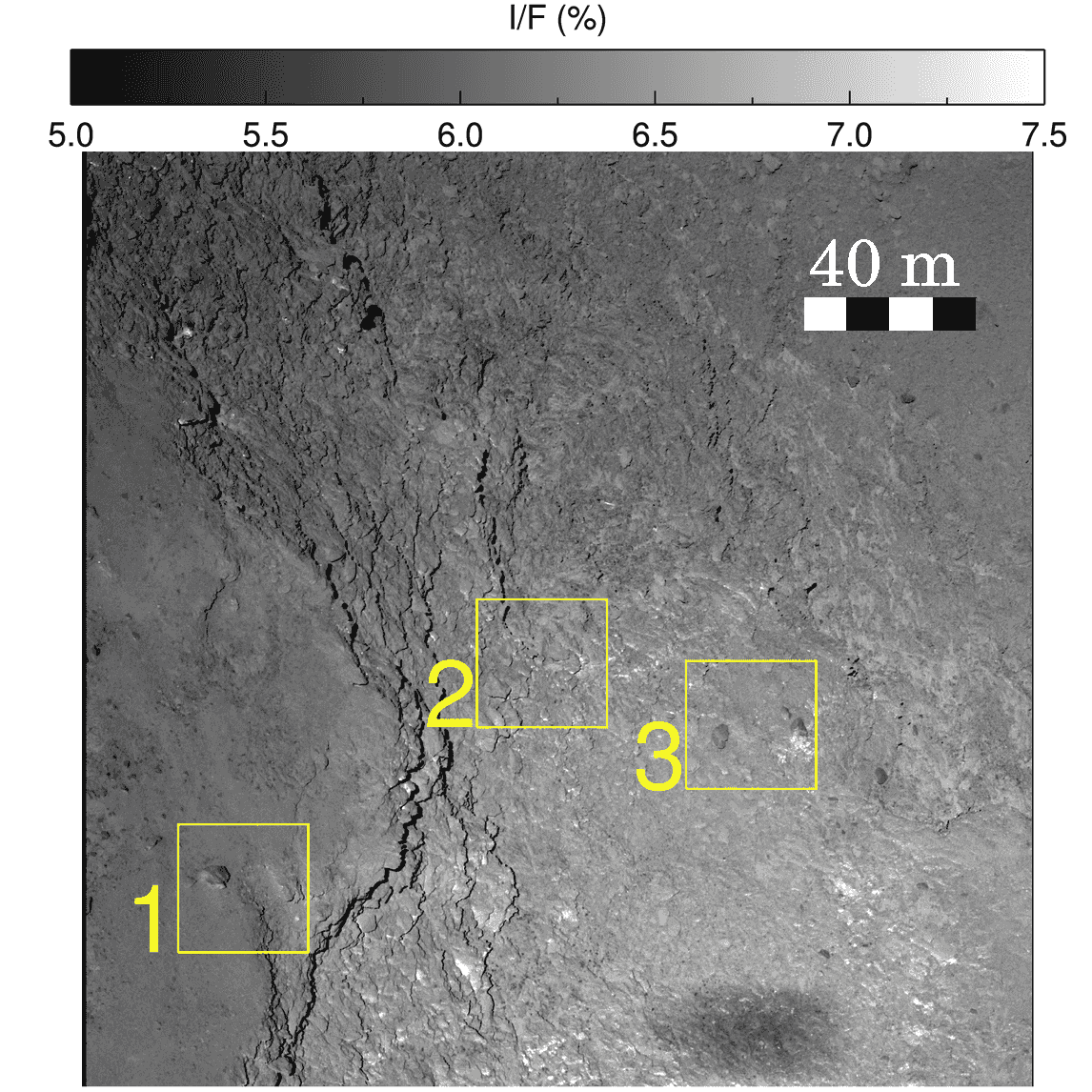
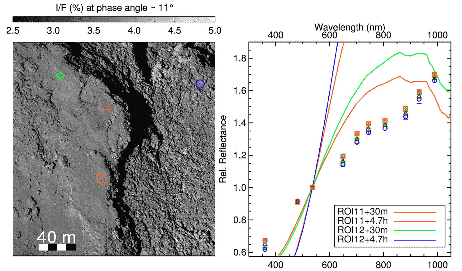
For this analysis, we sought surface elements, which were visible in almost every single sequence of observations, and which also exhibited heterogeneities in terms of absolute reflectance and of spectral slopes. We investigate here 3 such regions of interests (ROI), which are indicated in Fig. 6. The first ROI is over the Ash region and includes two metre-scale boulders as well as a spot ( the violet triangle in Fig. 7) which appears bright on every filter image of the dataset. The second ROI delimits a part of the Imhotep region including a strata head which appears dark and present a red spectral behaviour (site B in Fig. 8) as well as an outcrop exhibiting a blue spectral behaviour (site C in the same figure). Finally, in the third ROI, we investigated a couple of boulders which clearly appear darker than the surroundings at small phase angle (sites D and F in Fig. 9).
More in detail, ROI no. 1 of Fig. 6 is the clear example of the fine deposits on the layered terrain, this being demonstrated by the eroded niche margin on the right hand side, unveiling a set of cm-scale layers. ROI no. 2 focuses on the decimetre-scale layers with the possible presence of detaching blocks, as observed in Hathor region, but on different scales (Pajola et al., 2015). Finally, ROI no. 3, corresponds to a specific area with a cluster of boulders. The origin of this kind of boulders has not been here investigated, and it is not the purpose of this work, nonetheless, since there a cliff in close proximity it is not unreasonable to think that they may have detached from it, as observed and confirmed on many other locations on 67P/CG (Pajola et al., 2016).
In those ROIs, the spectrophotometric properties of different features was investigated by integrating the radiance factor, on Lommel-Seelinger disk-corrected images, inside squared boxes of 3x3 pixels (i.e. about 0.33x0.33m2).
The spectrophotometric measurements in ROI 1 (cf. Fig. 7) indicate that boulder named A is very red in term of spectral slope ( = 22.5
%/(100nm)). Its brighter side, indicated by the violet
triangle, is spectrally redder that the darker regions of the same boulder, indicated by the blue
circle, and as red as the nearby boulder on its left (green star). The bright spot indicates by the
brown triangle has a spectral slope less steep than that of boulder A ( = 20
%/(100nm)), but it is still redder compared to the relatively smooth regions
indicated by the red cross and orange square, whose spectral slope value is around 19
%/(100nm).
The behaviour of this surface element, i.e. high reflectance and also steep spectral slope, is
completely different compared to what previously observed by
Fornasier
et al. (2015); Pommerol
et al. (2015b); Fornasier et
al. (2016); Barucci et
al. (ress); Oklay
et al. (2016).
In those papers, the authors observed bright features on Hapi and in other
locations over the nucleus, which were associated with a small spectral slope
value ( < 10 %/(100nm)). This behaviour, i.e. high reflectance and
moderate spectral slope value, was linked to the presence of water-ice mixed to
refractory material.
We surmise that the red spectral slope of the bright feature in ROI 1 could be explained
through a difference in terms of composition: this feature would not be
enriched in water-ice but probably rather in minerals brighter than the
surroundings dark agglomerate. But it could also point out to a difference of
texture: this feature might be smoother or have a lower porosity than its
surroundings.
Additionally in this ROI, we observe that the top of A boulder (blue circle)
has a spectral behaviour similar to that of the surface layer at its feet (red
cross) indicating that both are covered by similar dark and red dust material.



The area contained in ROI 2 (cf. Fig.8) displays higher variations in the spectral behaviour compared to ROI 1, including both red features such as the one named B ( = 21.7 %/(100mn)), and bluer regions such as the one named C ( = 15%/(100mn)). Strata-head B is characterised by a steep spectral slope in the 650-1000 nm range (see the red cross symbol on Fig. 8) among the investigated areas. The measurement on the outcrop named C (where the orange square is placed) has a slightly higher radiance factor than the average in ROI 2 together with a bluer spectral behaviour than the surroundings.
The two metre-sized boulders located beneath the green cross and brown triangle have a spectral behaviour indistinguishable from the smoother region indicated by the blue circle, again pointing towards a similar composition in the uppermost dust layer.

In ROI 3, we have investigated two metre-scaled boulders which show again a lower opposition effect at small phase angles, designated D and F in Fig. 9 together with another boulder, named E, whose reflectance is indistinguishable from the surroundings at small phase angle. This region shows spectral slope variations as high as in ROI 2. Particularly interesting is feature D, which entails some bright patches at the feet of the boulder. The reflectance of those patches is up to 40% higher than the boulder’s. Despite the reflectance variation, both dark and bright components of boulder D show a similar very red spectral behaviour, redder than smooth surrounding regions (as the one indicated by the red cross) or of F and E boulders.
Our interpretation is that, possibly due to thermal stress, the sombre boulder has fractured and released chunks of fresh material that now constitute the bright patches. Both bright patches and boulder might have been later coated with organic-laced dust, and therefore exhibit such a red spectral slope (see Fig. 4).
5.1 Phase reddening
We plotted the spectral slope values versus the phase angle for each pixel of the available images is represented in Fig. 11.
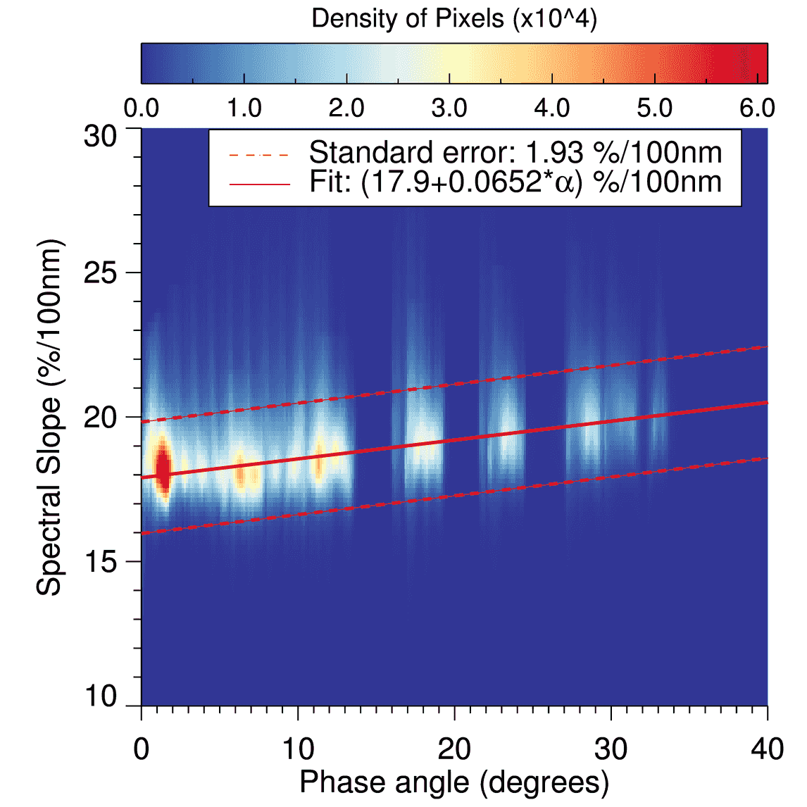
The phase reddening phenomenon is evident but characterized by a lower slope compared to the previous measurements (Fornasier et al., 2015): a linear regression of this dataset gave us a slope of = () nm and the spectral slope at zero phase angle is estimated to be (17.9 in the 743–535 nm range.
We note that Fornasier et al. (2016) also reported a strong decrease of the phase reddening effect comparing the spectral slope values averaged over the comet rotational period from Aug. 2014 datasets () and those acquired on April-Aug 2015 (), approaching the perihelion. They explain the decrease of the phase reddening effect as a results of the increasing level of activity that progressively removed the dust mantle. The fly-by data have intermediate phase reddening value comparable to those analysed in Fornasier et al. (2016). This can be interpreted as progressive dust mantle removal with changes of the surface properties, like the dust roughness.
6 Photometric analysis
In order to compare our results with the literature, we choose to apply the Hapke radiative transfer model to fit our dataset for the purpose of this study.
6.1 Hapke model and inversion procedure
The latest equation of Hapke model, in radiance factor, is defined by the expression:
| (4) |
where and are the effective cosine of incidence
and emergence angles, involving the topographic correction of the
facet by the macro-roughness shadowing function .
is the porosity factor, is the single-scattering albedo (or
SSA), is the shadow-hiding opposition effect (SHOE) term,
is the single or double lobe Heyney-Greenstein particle phase
function (or SPPF), is the coherent-backscattering opposition
effect (CBOE, Akkermans et al., 1988) term and is the
isotropic multiple scattering approximation function (also noted IMSA),
analytically described by the second-order approximative
Ambartsumian-Chandrasekhar function (Hapke, 2002).
Table 3 presents the free Hapke parameters
and their respective relationship with the scattering curve morphology
and properties of the surface. We name this version as Helfenstein-Hapke-Shkuratov
model (hereafter noted HHS model). A further qualitative and mathematical description
of the photometric model and its functions can be found in Helfenstein &
Shepard (2011)
or Hapke (2012) .
For data inversion we proceed as follow: first, a table of facets for each image is binned into a () cell grid (in steps of , which translates in to shells of 0.3 m in diameter) in respect to (incidence), (emergence) and (phase) angles. The RADF is averaged for each cell, mitigating any effect of variegation and poor pixels/facets. Cells with no pixels are removed from data. Then, the fitting procedure is focused on minimizing the between the measured and modelled RADF weighted by the number of facets on each active cell. 30 initial conditions of lowest are selected from 1000 random initial conditions (search grid of 0.01 interval) to undertake thorough minimization by the Broyden-Fletcher-Goldfarb-Shanno (L-BFGS-B) algorithm (Broyden, 1970; Zhu et al., 1997), available by Scipy Python package (Van Der Walt et al., 2011). L-BFGS-B solves non-linear problems by approximating the first and second derivatives in an iterative procedure to search for local solution. Finally, the 30 Hapke solutions are averaged to obtain the final solution and the uncertainties tied to each Hapke parameter.
| parameter | Description | Bounds |
|---|---|---|
| Particle Single-Scattering Albedo (SSA). | ||
| Asymmetric factor. Coefficient of the mono-lobe Heyney-Greenstein function. The average cosine of emergence angle of the single particle phase function (SPPF). | ||
| Porosity factor , is the filling factor. It is an addition introduced by Hapke (2008) corresponding to the role of superficial porosity in the scattering. The porosity factor and are constrained through the approximative formula | ||
| , | Amplitude and angular width of the SHOE. relates with micro-roughness and porosity. is a function of the specular component of the Fresnel reflectance . | , |
| , | Amplitude and angular width of the CBOE. , thus is inversely proportional to the mean photon path . is somehow connect to the particle scattering matrix. | , |
| Average macroscopic roughness slope of sub-pixel/sub-facet scale. |
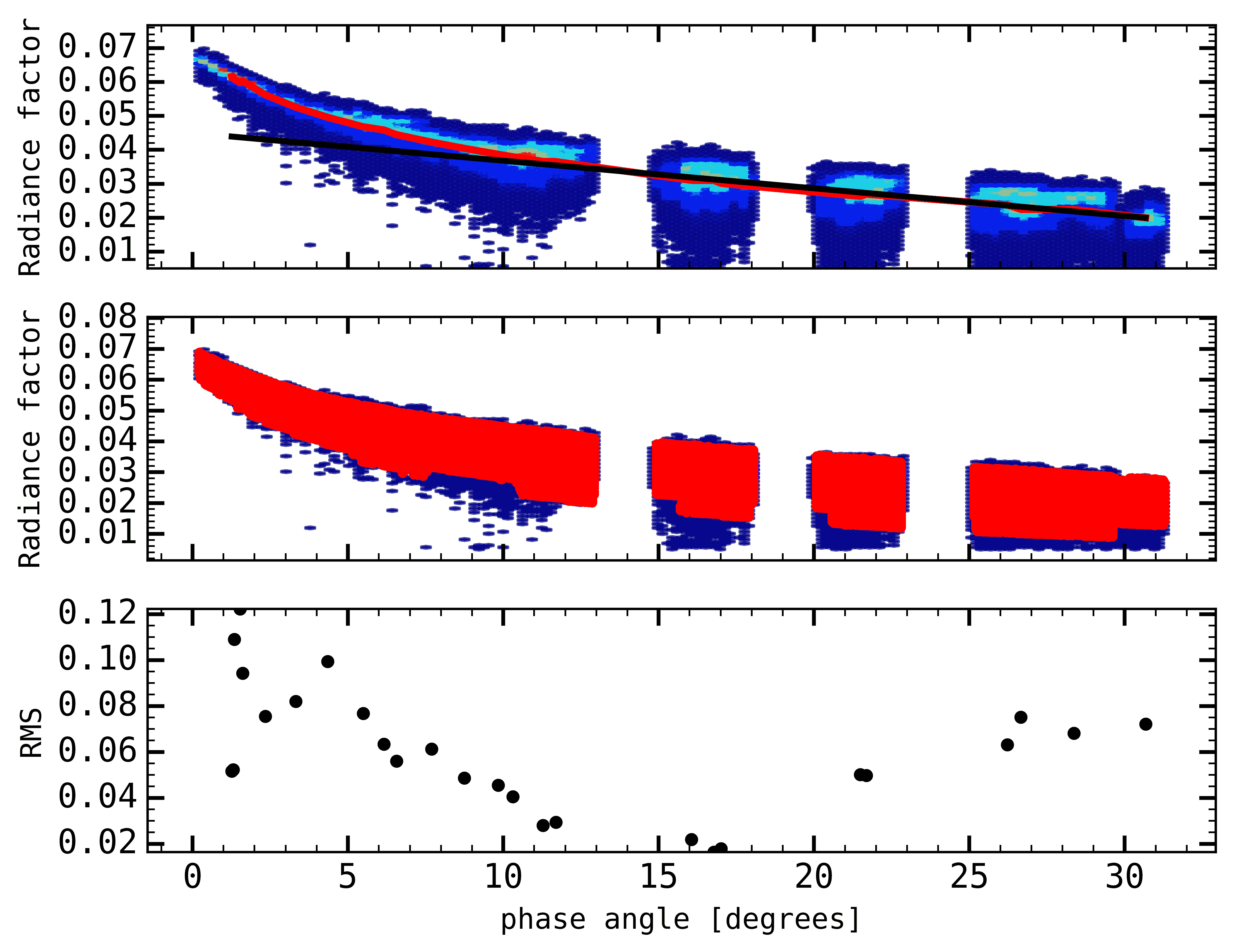
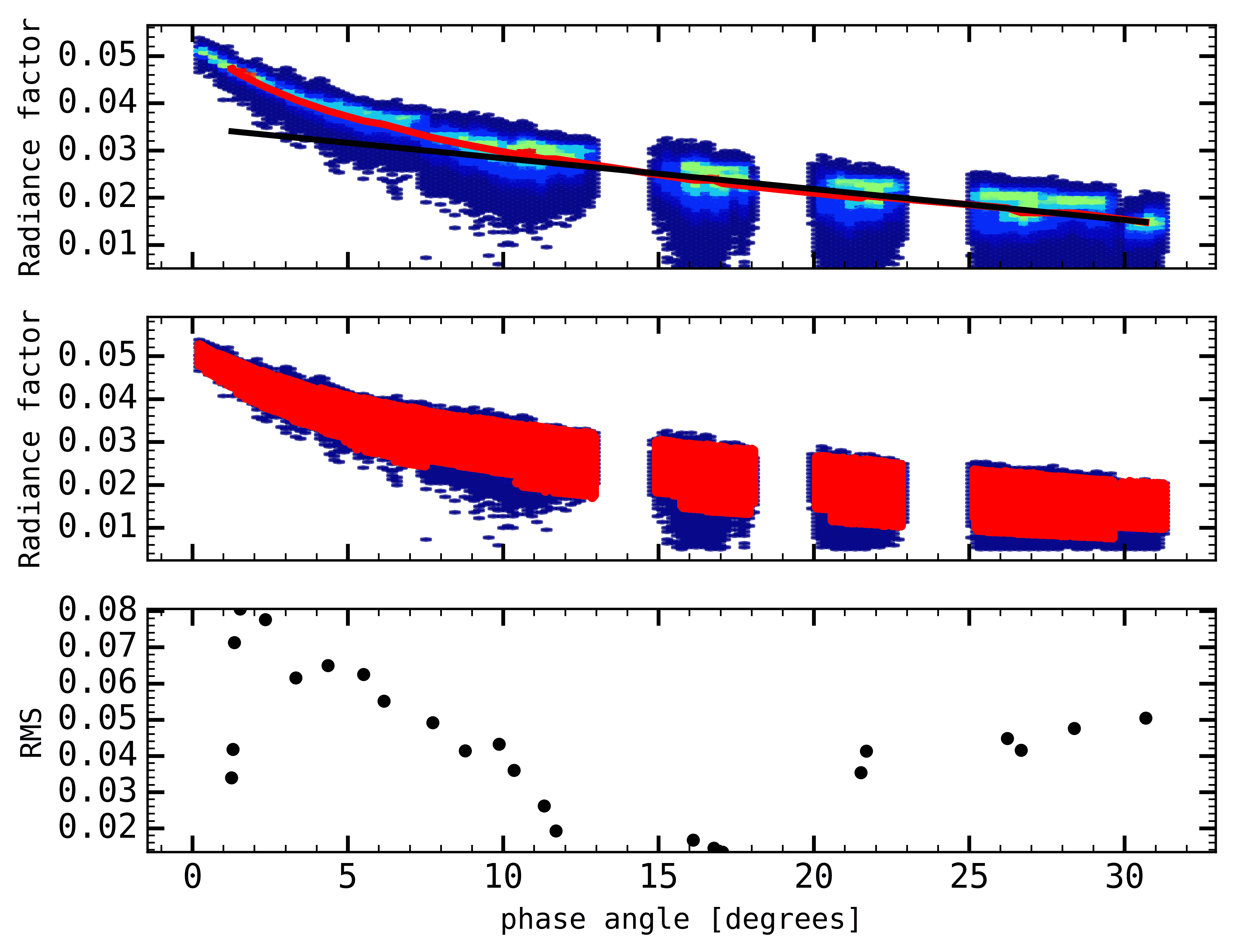
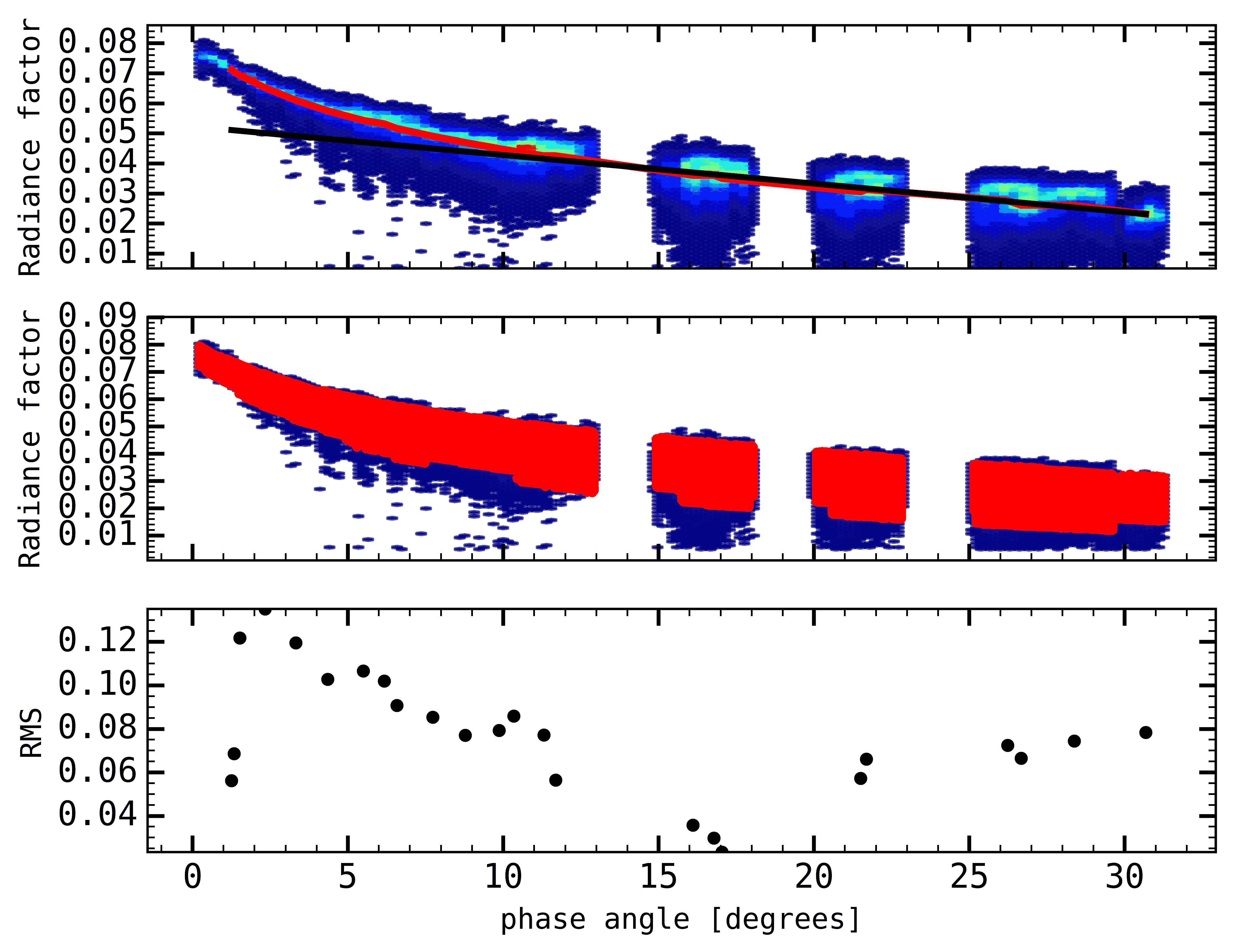
The photometric phase curve of the area, sampled between and , shows a similar behaviour in the 3 filters investigated (NAC F82, NAC F84 and NAC F88): linear up to , slightly non-linear up to and without any obvious sign of sharp spike at close opposition. We considered all the pixels covered by the shape model at and smaller than . We also further excluded those affected by the spacecraft shadow, i.e. . Thus, we used a total of 25 NAC F82, 24 NAC F84 and 23 NAC F88 images, which amounts to respectively, a total of 650,810, 633,674 and 647,776 active cells, reaching phase angles low enough to constrain the CBOE parameters. Most of the RADF spread is accounted by the assorted illumination conditions, while some few scattered cells are due to the poor description of the shape model for certain terrain slopes or overshadowed facets.
The HHS model has a maximum of 10 free parameters to be adjusted when the photometric sampling has a large enough coverage, i.e., from to for the and angles, and from to . However, the flyby data are limited to , leading us to apply only the single-term Heyney-Greenstein function to describe the backscattering lobe of the particle phase function. By also taking into account the approximative expression between and parameters (Table 4, Helfenstein & Shepard, 2011), we end up with 7 free parameters.
6.1.1 Role of the CBOE term
The coherent-backscattering mechanism rises from inter-intra-grain multiple scattering of secondary and higher orders. During our modelling, the first iteration of the inversion procedure revealed that CBOE parameters do not gradually converge on Hapke (2002) or HHS models to a single solution, which points out to redundancy of this mathematical addendum when a second opposition spike is not verified. This have also been emphasized in our analysis of the first approaching images of the whole northern hemisphere (Fornasier et al., 2015). Thus, visual inspection of phase curve have shown no presence of any sharp opposition spike to . Shepard & Helfenstein (2007) have also found out CBOE is negligible when analysing samples with Hapke (2002) model. Therefore, considering that coherent-backscattering is not expected to play a major role in the opposition effect of high absorbance surfaces (Shevchenko & Belskaya, 2010; Shevchenko et al., 2012), such as the cometary carbon-rich mantles, we decided to remove it from our final Hapke analysis. We note that also Masoumzadeh et al. (view) found the coherent back-scattering mechanism negligible in their analysis of the 14th Feb. 2015 data of the 67P/CG comet.
6.2 Results
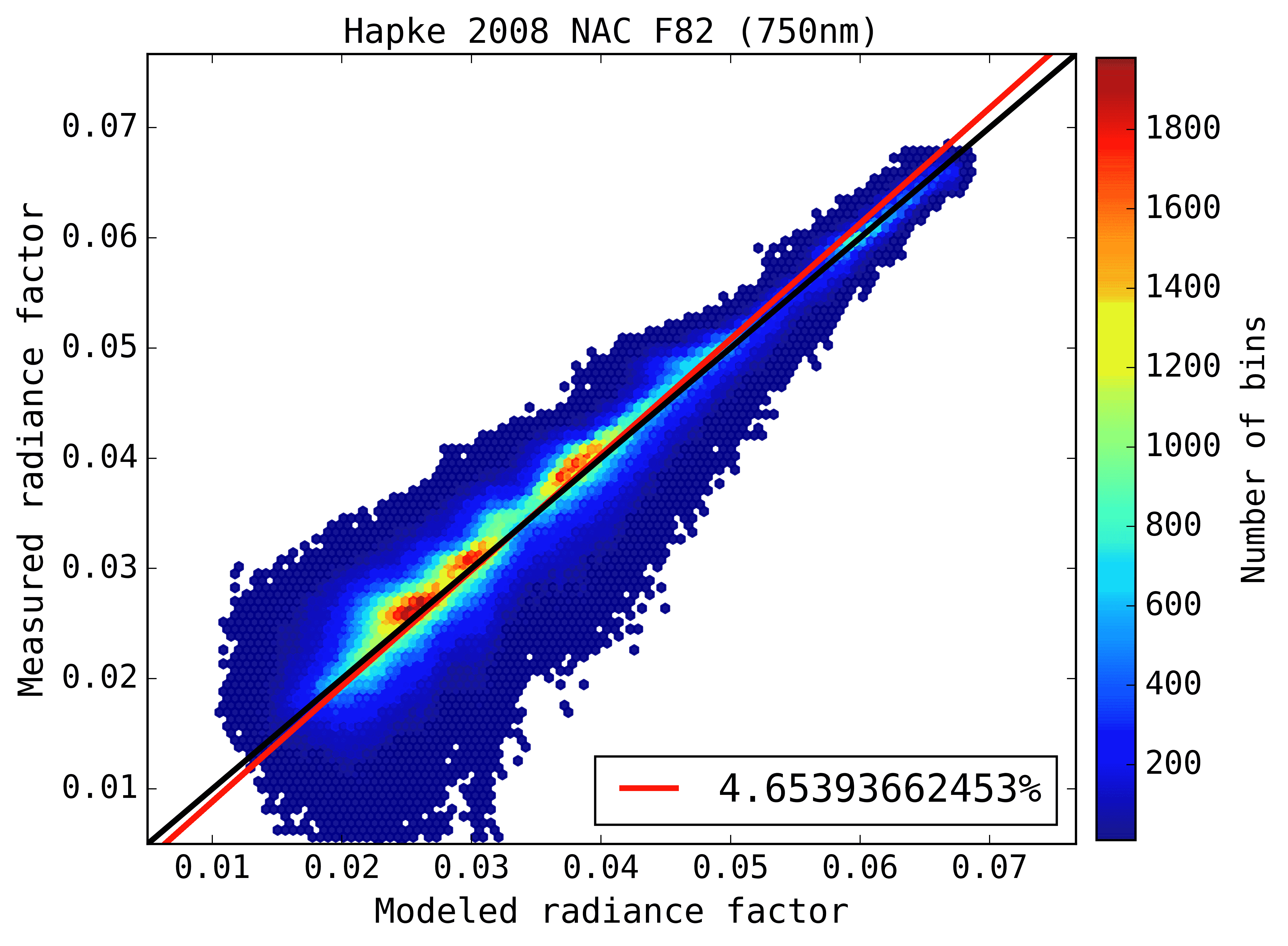
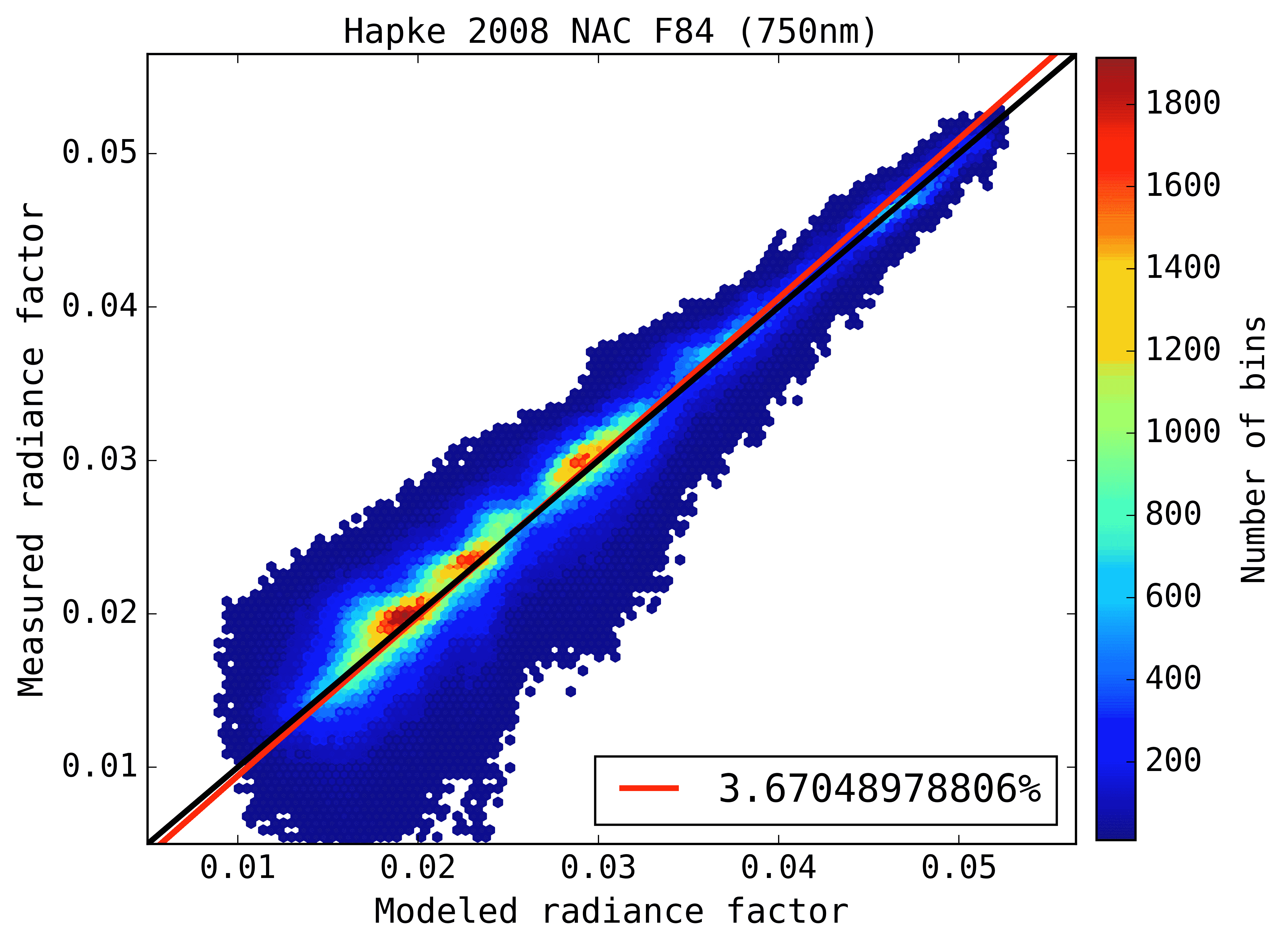
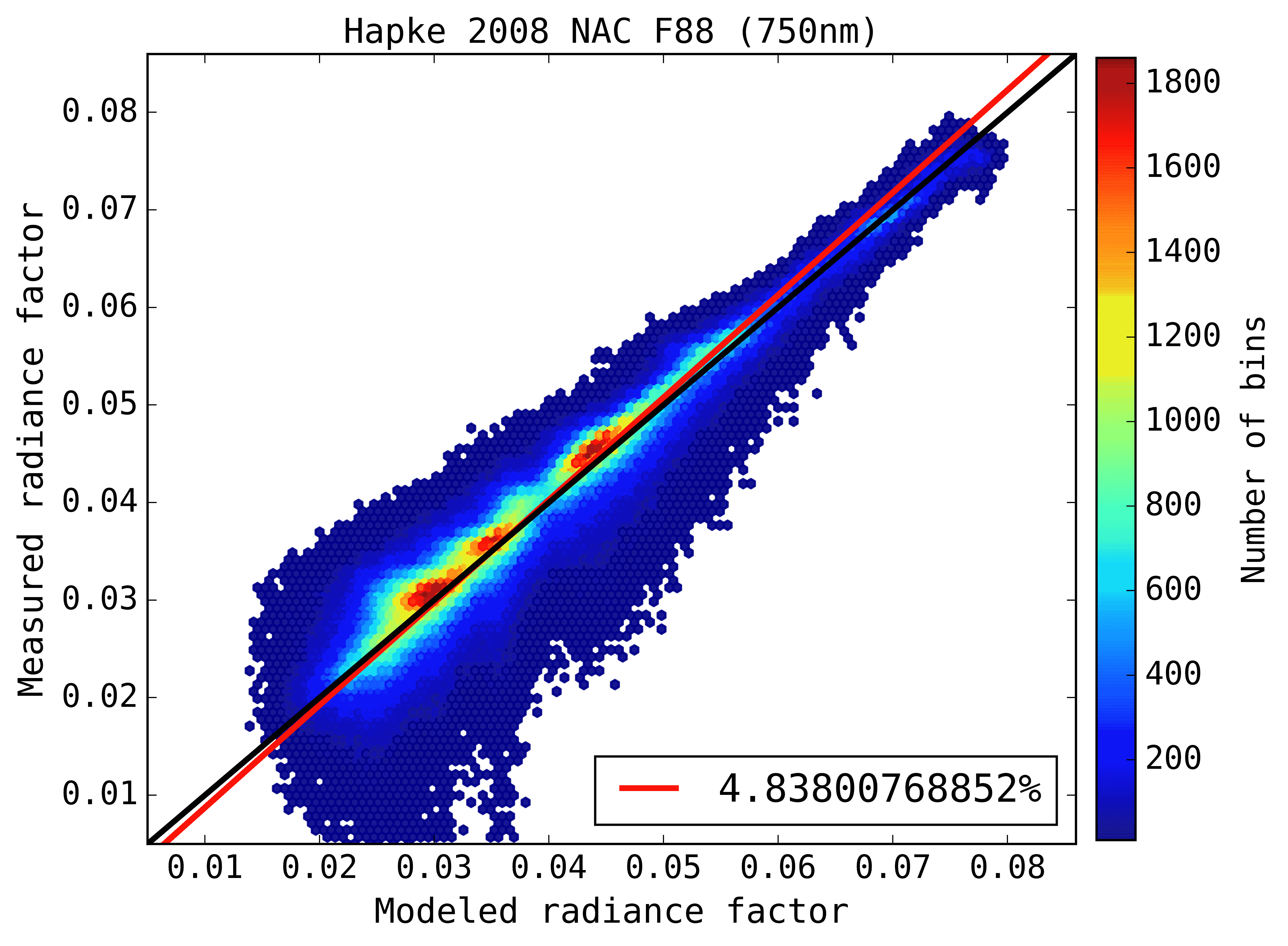
We fit to the three filters the five-parametric Hapke (2002) model and HHS model. For all of them, the models have successfully converged to a single solution. Figure 12 shows the observations together with the Hapke modelling for the three filters and the associated RMS. The total deviation of the modelled RADF compared to measured quantities (red line, Figures a-c-e) is no higher than , reaching almost 1:1 ratio in respect to the small phase angles images (black line). The best Hapke parameters found for the different filters reproduce correctly variations due to illumination conditions.
The final Hapke solutions are shown in Table 4, together with pre-perihelion solutions obtained from the OSIRIS images from 21 July to 6 August 2014 (, Fornasier et al., 2015). The parameters solution derived for the Ash-Imhotep area are very similar to those retrieved for the whole northern hemisphere. The area has a very small single-scattering albedo, medium backscattering particle phase function, strong shadow-hiding mechanism, high top-layer porosity and smooth macroscopic roughness. Ciarniello et al. (2015a), modelling the VIRTIS-M data of the 67P/CG comet for from July 2014 to February 2015, obtained higher () and (-0.42) values, but a value consistent with our work. The discrepancies in the results between OSIRIS and VIRTIS data are related to the different phase angle range used to compute the phase curve slope, and to the different forms of Hapke modelling adopted. Indeed, Ciarniello et al. neglected the opposition effect in their modelling. This results in a steeper (more negative) gsca value to account for the slope caused by opposition effect, and a steeper phase function that requires a higher single scattering albedo value to compensate for the overall measured I/F scale.
Rosetta provides for the first time the opportunity to derive the full set of parameters for a comet nucleus, particularly for the OE regime, as all the other cometary nuclei visited by spacecraft have been observed at . The surface analysed here and in Fornasier et al. (2015) is characterised by a large parameter, where according to Hapke (2012), SHOE amplitudes higher than the nominal limit of 1.0 might indicate the presence of sub-particle structures, casting shadows onto one another, which would cause SHOE mechanism to be further enhanced. As most part of the top surface of 67P/CG is possibly covered by resettled fluffy dust layer in the low-gravity environment, it is not unpredictable that mutual shadow hiding among particles should not be an enhanced mechanism. Furthermore, the superficial porosity of the Ash-Imhotep region () is indistinguishable compared to that derived for the northern hemisphere. This high value is similar to the one determined by the Philae measurements for the first tens of metres during the first rebound on the comet (, Kofman et al., 2015 ), and in agreement with the porosity value of fractal aggregates (Bertini et al., 2007; Levasseur-Regourd et al., 2007; Lasue et al., 2011) that are believed to be the best analogues of cometary dust. Low thermal inertia and high micro-roughness are proxy physical quantities to a high superficial porosity and a sharper SHOE. Laboratory experiments predict such correlation (Zimbelman, 1986; Piqueux & Christensen, 2009). Therefore, as expected, our results are in agreement with high micro-roughness (, Kamoun et al., 2014) obtained through re-analysis of radar echo from Arecibo observatory and the low therma inertia of provided by MUPUS instrument on-board Philae (Spohn et al., 2015).
Briefly, , , and are the only Hapke (2002) parameters that can be compared to the literature. The Ash-Imhotep area along with all the northern hemisphere (Fornasier et al., 2015; Ciarniello et al., 2015a) show similar photometric behavior to other nuclei in the visible spectral range, specially 9P/Tempel 1 (, , and , Li et al., 2007a) and 103P/Hartley 2 (, , and , Li et al., 2013). The geometric albedo of the 67P/CG nucleus has an intermediate value compared to that found for 81P/Wild 2 (,Li et al., 2009) and 19P/Borrelly (, Li et al., 2007b). Moreover, 67P/CG shows lower than all other nuclei. None of previous spacecraft comets attained the same spatial resolution than Rosetta in their cometary images. However, both objects that present similar Hapke parameters, Tempel 1 and Hartley 2, are those that also demonstrate overflow of extremely smooth and fine material in their surface, in a comparable manner to the Hapi region on 67P/CG.
| Model | Filter | Porosity | |||||||
| H2002a | F82 | - | - | ||||||
| H2002† | F84 | - | - | ||||||
| H2002 | F82 | - | - | ||||||
| H2002 | F88 | - | - | ||||||
| HHSa | F82 | ||||||||
| HHS‡ | F84 | ||||||||
| HHS | F82 | ||||||||
| HHS | F88 | ||||||||
Hapke 2002 model.
Helfenstein-Hapke-Shkuratov model (see section 6.1 ).
Obtained by (Fornasier et al., 2015), from OSIRIS data
6.3 Investigation of bright patches and dark boulders
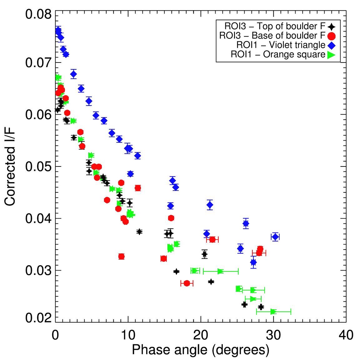
As mentioned in section 4, the Fig. 13 shows the phase curves of four selected areas which have different morphology, including a sombre boulder and a bright spot. The bright spot investigated here corresponds to the violet triangle in ROI1, while the sombre boulder corresponds to the feature D in ROI3. As expected, we observe that the reflectance of this feature, which appears bright under every illumination conditions in every image, is larger than that of the dark boulder. We also note, for the bright spot, that the opposition effect surge at small phase angle is not pronounced as what could be expected in the case of water-ice rich material. We also report that the dimensions of the dark boulder are only merely above the vertical and horizontal accuracy of the 3D model of the region: hence though this feature is visible in the 3D model, its reconstitution lead to a disparity in the generated phase angles.
| Feature | w649nm | gSCA | BSH,0 | hSH | Porosity | |
|---|---|---|---|---|---|---|
| Bright spot (ROI 1) | 0.0680.002 | -0.310.02 | 1.5830.25 | 0.0890.01 | 0.810.02 | 0.077 |
| Sombre boulder (ROI 3) | 0.03850.002 | -0.450.03 | 1.5260.41 | 0.0870.01 | 0.820.02 | 0.064 |
The Hapke parameters for the bright spot and the dark boulder present a clear dichotomy between the two objects (see Table 5). The bright spot is characterized by a high normal and single-scattering albedo and a flatter phase curve slope (gsca). The reverse is measured for the dark boulder. As the phase curve slope is inversely proportional to the geometric albedo (Déau et al., 2013), the same SHOE width and amplitude might indicate that the micro-roughness structure in the top layers is preserved.
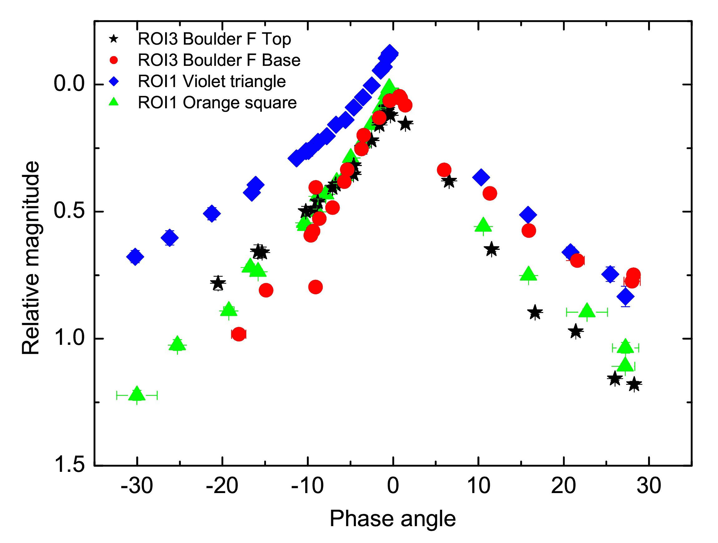
The radiance factor values normalized to the averaged comet albedo (0.068) and converted to magnitudes, are presented in Fig. 14. One of the considered areas (violet triangle at ROI1) is noticeably brighter while other three areas have similar albedos. An asymmetry of phase curves measured before and after opposition is well seen. It becomes evident at a phase angle larger than 10-15∘ and can be most probably explained by variations of local elevation. The Ash terrain, which is a more plane surface, shows the smallest difference between phase curves before and after opposition.
To compare phase behaviours of selected areas, we considered only phase angles up to 10 deg where an influence of the relief is less significant.
The brighter region exhibits a distinct opposition effect as contrary to darker regions, for which the magnitude-phase dependences are linear at small phase angles.
The linear phase slopes are 0.0450.002 mag/deg (green star at the top of boulder D), 0.0620.005 mag/deg (blue ellipse at the feet of boulder D) and 0.0510.002 mag/deg (orange square at the base of the bright spot in ROI1).
The differences in phase slopes are most probably related to the variation of surface roughness.
The boulder which looks darker than its surroundings should have considerably smoother surface compared to the surface at its base.
The values of phase slopes found for selected areas of the comet are within typical values observed for comets (e.g. Li et al. (2007b)), and in particular similar to what has been found for the global 67P/CG (0.0470.002 mag/deg for 7∘) from early resolved images of the nucleus (Fornasier et al., 2015), and in particular for the sombre boulder and the smooth Ash terrain.
6.4 Comparison to radio-goniometric measurements
The February 2015 flyby provides the first-time opportunity to retrieve and analyse photometric parameters at spatial resolution comparable to those obtained through laboratory experiments. Recently, in the framework of Rosetta mission, new spectro-photometric measurements on cometary analogues were performed at the University of Bern using the PHIRE-2 radio-goniometer and the SCITEAS simulation chamber (Jost et al., 2016; Pommerol et al., 2011; Pommerol et al., 2015a; Pommerol et al., 2015b). The PHIRE-2 radio-goniometer measured the scattering curve before and after sublimation of inter/intra-mixture samples of m ice particles, 0.2 wt% carbon black and 0.1 wt% tholins at 750 nm. The inter- and intra- mixtures are produced using different sample preparation protocols and differ by the structure of the sample at the scale of the individual grains. The dust and water-ice grains are individually separated in the inter-mixture, whereas minerals grains are contained inside the water-ice grains for intra-mixture preparations. Each experiment was set up into a cm3 sample holder, providing 4 combinations of cometary analogue surfaces plus an ice-less combination of tholins (33%) and carbon black (66%), we refer the reader to Poch et al. (2016a) for more details on the preparation methods. The resolution of comet data from the 2015-February fly-by is of 11cm/pxl, whereas the analogue surfaces are about only 10 times smaller, placing them as an equivalent to the highest-resolved surface unit of 67P/CG up to now.
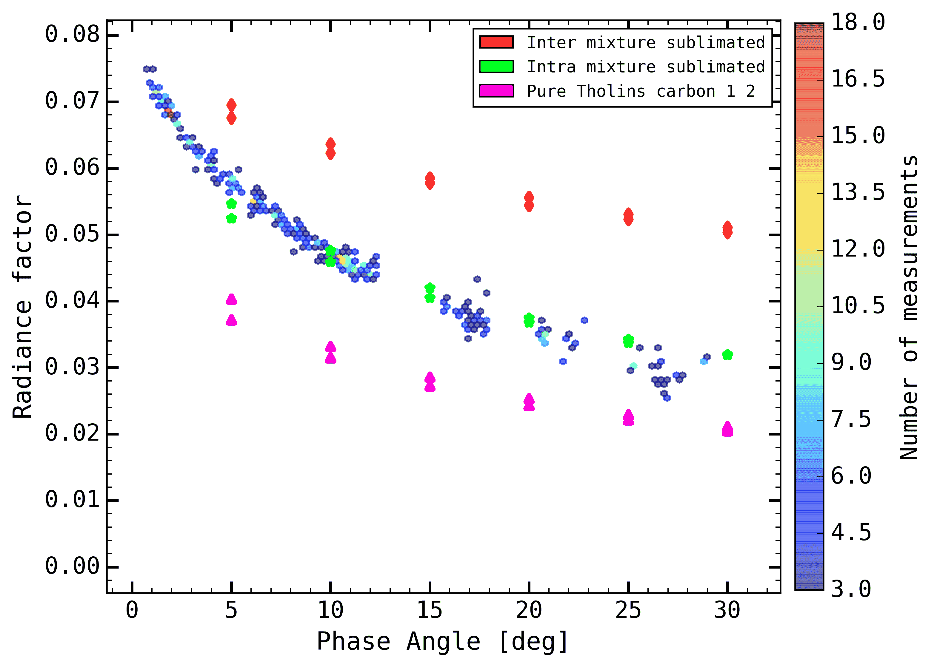
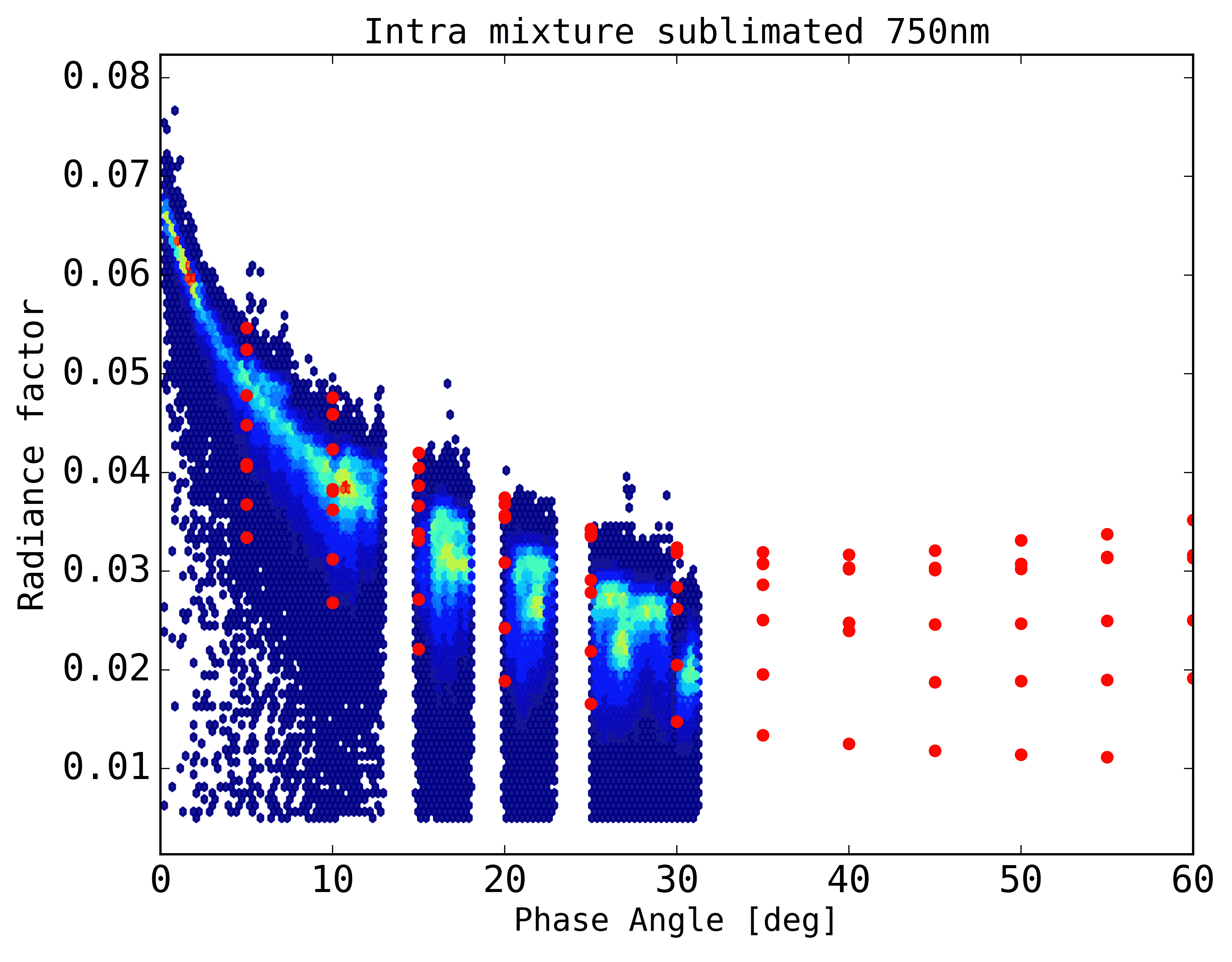
As the cometary surfaces investigated here are essentially ice-free, we compare the photometric properties derived from NAC F88 flyby data to laboratory data obtained for the fully sublimated state of 3 different types of cometary surfaces analogues (Jost et al., in preparation). The laboratory reflectance data were measured with the PHIRE-2 radio-goniometer at a central wavelength of 750 nm. The comparison, as presented in Figure 15a for incidence angle equal to zero, clearly indicates that the sublimated “intra-mixture” sample (see Fig. 15b) displays a similar scattering curve in the phase angle range of the fly-by. The three samples show quite similar phase curve slope, whereas inter-mixture is slightly flatter than intra-mixture for . Nonetheless, the intra-mixture is the only sample to fit the 67P/CG phase curve in absolute radiance factor and also in slope.
At larger phase angles (), the intra-mixture scattering curve becomes wider and strongly forward scattering, which is very different from what is observed by Ciarniello et al. (2015b) for , where the overall reflectance goes fainter. This is essentially due to the effect of large scale topography and roughness that are absent from the laboratory samples but dominate the photometry of the nucleus at these large phase angle. Moreover, radiometric measurements were not obtained to , which does not allow us to infer the shape and magnitude of the opposition surge.
According to Poch et al. (2016b), an intra-mixed surface has as characteristic the formation of mantles of high internal cohesiveness and with episodic and bigger release of fragments during sublimation than inter-mixed counterpart. Under the optical coherence tomographic scan (Jost et al., in preparation), intra-mixtures also presents a higher superficial roughness than inter-mixtures, which would also indicate an higher superficial porosity, as found by the photometric modelling of the comet. However, none of these surface properties have been quantitatively characterized yet.
7 Discussions and outlook
The analysis of the decimetre-scaled observations of the comet 67P/CG with the OSIRIS instrument reveals that the photometric parameters of the flown-by region are similar to those of the whole nucleus. The comet surface is noticeably dark, its uppermost layer is very porous, and it preferentially backscatters the reflected light (see Table 4). The spectrophotometric analysis of smooth and dusty area on both Ash and Imhotep regions indicate similar properties in terms of texture and composition. These terrains are found to be among the reddest in term of spectral slope on the comet surface. We note here that the texture of the material covering the Ash part of the flown-by region appear similar to the observations of the ROLIS instrument on-board the Philae lander, as presented in Mottola et al. (2015). We also observe similar textures in parts of the flown-by region: a smooth regolith with the presence of decimetre and metre-sized boulders, alone or as part of clusters, and alcoves.
However, the spectrophotometric analysis also points out to local variations in terms of reflectance and colours (respectively up to 40% and 50%) pointing to local heterogeneities at the metre and decimetre scale associated to peculiar morphological features such as boulders. Heterogeneities were confirmed at larger scales by OSIRIS and at smaller scales by CIVA onboard Philae (Bibring et al., 2015), both in terms of texture and composition.
In their study of the Agilkia region (where the Philae lander made its first touch down), La Forgia et al. (2015) found that the area closest to outcrops and cliffs were those exhibiting the reddest spectral behaviour, which is in agreement with our observations of Fig. 10. Furthermore, they also investigated the spectrophotometric difference between fine deposits and outcrops area, and they found that fine deposits have a relatively bluer spectrum than outcrops, a result which is in agreement with our observations in the different ROIs.
The presence and origin of fine deposits in the Agilkia and Ash regions have already been investigated and discussed in Thomas et al. (2015a); La Forgia et al. (2015): the authors speculate that those fine deposits might be the results of airfall of material originating from other active regions, such as Hapi.
The investigation of the origin of fine deposits in the flyby-region is beyond the scope of this paper, yet we can retain that an airfall hypothesis could explain why the top of outcrops and boulders have a spectral behaviour similar to pebble-less neighbouring surfaces.
When investigating the median spectral slope of the area flown-by, and the spectra of large boulder-less surfaces (1.5x1.5m2), as in La Forgia et al. (2015), we found likewise that the surface was revealing a global red spectral behaviour (Smed = 17.7%/100nm at 1∘ of phase angle) without any evidence of band features (with the exception of the cometary emission over-flux) in the near-UV to near-IR domain. According to VIRTIS results, the red spectral behaviour is compatible with an organic-rich composition (Capaccioni et al., 2015; Filacchione et al., 2016).
When comparing our dataset to Jost
et al. (2016), we found that a
intra-mixture composed of tholins and of carbon black was a best-match in terms
of photometric properties. However, when comparing spectra of fresh and sublimated
samples of intra-mixture and inter-mixture of water-ice, tholins and minerals (olivine and smectite),
we found that no sample would match well the spectrophotometric properties of
the surface layer of the flown-by region, as depicted in Fig. 16.
Reflecting that such samples are not a proxy for the comet’s composition, we can
nevertheless remark that the after-sublimation intra-mixture sample was a better
match than the inter-mixture sample in terms of photometric properties.
As we have previously mentioned, in this region, the bright spots display a steep spectral slope value, which is not normally associated to terrains enriched in water-ice on the comet 67P/CG. Moreover, the reflectances of the bright spot is not as high (3 to 8 times the reflectance of the surroundings) as normally observed in exposed water-ice spots on the comet (Pommerol et al., 2015b; Barucci et al., ress; Fornasier et al., 2016).
All of the observed boulders of the flown-by region showing a lower reflectance at small phase angle,
relative to their surroundings, also exhibit a red spectral behaviour, often much redder than the
surroundings. However, also brighter regions in or close to the dark boulders, like the one observed
on boulders A or F often show a red spectral behaviour very close to that of the
darker boulders. This indicates that the uppermost composition must be similar
in the aforementioned structures, and that the different reflectance may be related
to grain size properties, with brightest features having probably smaller grain size.
Yet, those measurements give an extraordinary insight at the decimetre-scaled structure of the nucleus and surely a preview of the upcoming OSIRIS observations as the ROSETTA spacecraft will orbit, in the coming months, closer and closer to the nucleus of comet 67P/Churyumov-Gerasimenko.
Acknowledgements
OSIRIS was built by a consortium of the Max-Planck-Institut für Sonnensystemforschung, Göttingen, Germany, CISAS–University of Padova, Italy, the Laboratoire d’Astrophysique de Marseille, France, the Instituto de Astrofísica de Andalucia, CSIC, Granada, Spain, the Research and Scientific Support Department of the European Space Agency, Noordwijk, The Netherlands, the Instituto Nacional de Técnica Aeroespacial, Madrid, Spain, the Universidad Politéchnica de Madrid, Spain, the Department of Physics and Astronomy of Uppsala University, Sweden, and the Institut für Datentechnik und Kommunikationsnetze der Technischen Universität Braunschweig, Germany. The support of the national funding agencies of Germany (DLR), France (CNES), Italy (ASI), Spain (MEC), Sweden (SNSB), and the ESA Technical Directorate is gratefully acknowledged.
Rosetta is an ESA mission with contributions from its member states and NASA. Rosetta’s Philae lander is provided by a consortium led by DLR, MPS, CNES and ASI.
The SPICE, SPICE/DSK libraries and PDS resources are developed and maintained by NASA. The authors wish to thank Nathan Bachmann and his colleagues for their guidance.
References
- A’Hearn et al. (2005) A’Hearn M. F., et al., 2005, Science, 310, 258
- A’Hearn et al. (2011) A’Hearn M. F., et al., 2011, Science, 332, 1396
- Acton (1996) Acton C. H., 1996, Planet. Space Sci., 44, 65
- Akkermans et al. (1988) Akkermans E., Wolf P., Maynard R., Maret G., 1988, Journal de Physique, 49, 77
- Barucci et al. (2011) Barucci M. A., Dotto E., Levasseur-Regourd A. C., 2011, A&ARv, 19, 48
- Barucci et al. (ress) Barucci et al. In press, A&A
- Bertin (2011) Bertin E., 2011, STIFF: Converting Scientific FITS Images to TIFF, Astrophysics Source Code Library (ascl:1110.006)
- Bertini et al. (2007) Bertini I., Thomas N., Barbieri C., 2007, A&A, 461, 351
- Bibring et al. (2015) Bibring J.-P., et al., 2015, Science, 349
- Broyden (1970) Broyden C. G., 1970, IMA Journal of Applied Mathematics, 6, 76
- Capaccioni et al. (2015) Capaccioni F., et al., 2015, Science, 347, aaa0628
- Ciarniello et al. (2015a) Ciarniello M., et al., 2015a, Astronomy & Astrophysics, 583, A31
- Ciarniello et al. (2015b) Ciarniello M., et al., 2015b, A&A, 583, A31
- De Sanctis et al. (2015) De Sanctis M. C., et al., 2015, Nature, 525, 500
- Déau et al. (2013) Déau E., Flandes A., Spilker L. J., Petazzoni J., 2013, Icarus, 226, 1465
- El-Maarry et al. (2015) El-Maarry M. R., et al., 2015, A&A, 583, A26
- Filacchione et al. (2016) Filacchione G., et al., 2016, Icarus, 274, 334
- Fornasier et al. (2004) Fornasier S., Dotto E., Marzari F., Barucci M. A., Boehnhardt H., Hainaut O., de Bergh C., 2004, Icarus, 172, 221
- Fornasier et al. (2007) Fornasier S., Dotto E., Hainaut O., Marzari F., Boehnhardt H., De Luise F., Barucci M. A., 2007, Icarus, 190, 622
- Fornasier et al. (2009) Fornasier S., et al., 2009, A&A, 508, 457
- Fornasier et al. (2015) Fornasier S., et al., 2015, A&A, 583, A30
- Fornasier et al. (2016) Fornasier et al. submitted 2016, Science
- Giacomini et al. (2016) Giacomini L., et al., 2016, Mem. Soc. Astron. Italiana, 87, 159
- Hapke (1993) Hapke B., 1993, Theory of reflectance and emittance spectroscopy
- Hapke (2002) Hapke B., 2002, Icarus, 157, 523
- Hapke (2012) Hapke B., 2012, Theory of Reflectance and Emittance Spectroscopy, second edn. Cambridge University Press, http://dx.doi.org/10.1017/CBO9781139025683
- Hasselmann et al. (2016) Hasselmann P. H., Barucci M. A., Fornasier S., Leyrat C., Carvano J. M., Lazzaro D., Sierks H., 2016, Icarus, 267, 135
- Helfenstein & Shepard (2011) Helfenstein P., Shepard M. K., 2011, Icarus, 215, 83
- Jorda et al. (2010) Jorda L., Spjuth S., Keller H. U., Lamy P., Llebaria A., 2010, in Computational Imaging VIII. p. 753311, doi:10.1117/12.838893
- Jost et al. (2016) Jost B., Pommerol A., Poch O., Gundlach B., Leboeuf M., Dadras M., Blum J., Thomas N., 2016, Icarus, 264, 109
- Kamoun et al. (2014) Kamoun P., Lamy P. L., Toth I., Herique A., 2014, A&A, 568, A21
- Keller et al. (2007) Keller H. U., et al., 2007, Space Science Reviews, 128, 433
- Kofman et al. (2015) Kofman W., et al., 2015, Science, 349
- Küppers et al. (2007) Küppers M., et al., 2007, A&A, 462, L13
- La Forgia et al. (2015) La Forgia F., et al., 2015, A&A, 583, A41
- Lasue et al. (2011) Lasue J., Botet R., Levasseur-Regourd A. C., Hadamcik E., Kofman W., 2011, Icarus, 213, 369
- Levasseur-Regourd et al. (2007) Levasseur-Regourd A. C., Mukai T., Lasue J., Okada Y., 2007, Planet. Space Sci., 55, 1010
- Li et al. (2007a) Li J.-Y., et al., 2007a, Icarus, 187, 41
- Li et al. (2007b) Li J.-Y., A’Hearn M. F., McFadden L. A., Belton M. J. S., 2007b, Icarus, 188, 195
- Li et al. (2009) Li J.-Y., A’Hearn M. F., Farnham T. L., McFadden L. A., 2009, Icarus, 204, 209
- Li et al. (2013) Li J.-Y., et al., 2013, Icarus, 222, 559
- Lucchetti et al. (2016) Lucchetti A., et al., 2016, A&A, 585, L1
- Masoumzadeh et al. (view) Masoumzadeh N., et al., under review, A&A
- Massironi et al. (2015) Massironi M., et al., 2015, Nature, 526, 402
- Mottola et al. (2015) Mottola S., et al., 2015, Science, 349
- Oklay et al. (2016) Oklay N., et al., 2016, A&A, 586, A80
- Pajola et al. (2015) Pajola M., et al., 2015, A&A, 583, A37
- Pajola et al. (2016) Pajola M., et al., 2016, A&A, 592, A69
- Piqueux & Christensen (2009) Piqueux S., Christensen P. R., 2009, Journal of Geophysical Research (Planets), 114, E09005
- Poch et al. (2016a) Poch O., Pommerol A., Jost B., Carrasco N., Szopa C., Thomas N., 2016a, Icarus, 266, 288
- Poch et al. (2016b) Poch O., Pommerol A., Jost B., Carrasco N., Szopa C., Thomas N., 2016b, Icarus, 267, 154
- Pommerol et al. (2011) Pommerol A., Thomas N., Affolter M., Portyankina G., Jost B., Seiferlin K., Aye K.-M., 2011, Planetary Space Science, 59, 1601
- Pommerol et al. (2015a) Pommerol A., Jost B., Poch O., El-Maarry M. R., Vuitel B., Thomas N., 2015a, Planetary Space Science, 109, 106
- Pommerol et al. (2015b) Pommerol A., et al., 2015b, A&A, 583, A25
- Preusker et al. (2015a) Preusker F., et al., 2015a, European Planetary Science Congress 2015, 10, EPSC2015
- Preusker et al. (2015b) Preusker F., et al., 2015b, A&A, 583, A33
- Shepard & Helfenstein (2007) Shepard M. K., Helfenstein P., 2007, Journal of Geophysical Research (Planets), 112, 3001
- Shevchenko & Belskaya (2010) Shevchenko V. G., Belskaya I. N., 2010, in European Planetary Science Congress 2010. p. 738
- Shevchenko et al. (2012) Shevchenko V. G., et al., 2012, Icarus, 217, 202
- Sierks et al. (2015) Sierks H., et al., 2015, Science, 347, aaa1044
- Spohn et al. (2015) Spohn T., et al., 2015, Science, 349
- Thomas et al. (2015a) Thomas N., et al., 2015a, Science, 347, aaa0440
- Thomas et al. (2015b) Thomas N., et al., 2015b, A&A, 583, A17
- Tubiana et al. (2015) Tubiana C., et al., 2015, A&A, 583, A46
- Van Der Walt et al. (2011) Van Der Walt S., Colbert S. C., Varoquaux G., 2011, Computing in Science & Engineering, 13, 22
- Van Der Walt et al. (2014) Van Der Walt S., et al., 2014, PeerJ,
- Vincent et al. (2015) Vincent J.-B., et al., 2015, Nature, 523, 63
- Zhu et al. (1997) Zhu C., Byrd R. H., Lu P., Nocedal J., 1997, ACM Trans. Math. Softw., 23, 550
- Zimbelman (1986) Zimbelman J. R., 1986, Icarus, 68, 366