A trapped atom interferometer with ultracold Sr atoms
Abstract
We report on a trapped atom interferometer based on Bragg diffraction and Bloch oscillations with alkaline-earth-metal atoms. We use a Ramsey-Bordé Bragg interferometer with 88Sr atoms combined with Bloch oscillations to extend the interferometer time. Thanks to a long coherence time for Bloch oscillations of 88Sr atoms, we observed interference up to s evolution time in the lattice. A detailed study of decoherence sources during the Bloch phase is also presented. While still limited in sensitivity by lattice lifetime and beam inhomogeneity this result opens the way to high contrast trapped interferometers with extended interrogation time.
I Introduction
Due to their high sensitivities and accuracy, next generation atom interferometers are the focus of study in several laboratories around the world tin (2014). Research in the field has centered on increasing the interferometric path, in order to vastly improve the sensitivity of these devices. Recent advances in atom interferometer sensitivity pave the way for these devices to be used in precision tests of fundamental physical theories such as quantum theory Gillot et al. (2013); Kovachy et al. (2015); Lopes et al. (2015); Manning et al. (2015), quantum gravity Amelino-Camelia et al. (2009) and gravitation Biedermann et al. (2015); Hartwig et al. (2015); Zhou et al. (2015); Duan et al. (2016), determination of physical constants Bouchendira et al. (2011); Rosi et al. (2014), and, eventually, observation of gravitational waves in the low frequency regime Tino and Vetrano (2007); Dimopoulos et al. (2009); Hohensee et al. (2011); Graham et al. (2013).
The most direct way of increasing the sensitivity of atom interferometers is to simply increase the interferometer time . For vertical atom interferometers, this can be achieved by using long vacuum tubes to increase the free-fall time Kovachy et al. (2015); Zhou et al. (2011); Hartwig et al. (2015). Provided that atomic samples are sufficiently cold and there are no limitations due to laser beam geometry, for a 10 m vacuum tube the interferometer time can be 1s. However, is proportional to the square root of the tube length and a much more efficient way of extending is by trapping the atoms against gravity during the interferometer sequence itself.
While the majority of the atom interferometers considered rely on Raman transitions in alkali atoms, recent experiments have demonstrated the feasibility of performing Bragg interferometry with ultracold alkaline-earth-metal(-like) atoms Mazzoni et al. (2015); Jamison et al. (2014). Furthermore, long coherence time of Bloch oscillations has been observed in 88Sr Poli et al. (2011); Tarallo et al. (2014). Hence, strontium is a possible candidate for interferometric schemes that take advantage of the long coherence time of Bloch oscillations in order to extend the interferometer time by trapping the atoms in a 1-D vertical optical lattice, providing an alternative avenue towards dramatically increasing the sensitivity of atom interferometers without the need for large atomic fountains.
As well as extending the interferometer time through coherent Bloch oscillations, the lattice can act as a waveguide upon the atomic samples, limiting their radial (horizontal) expansion McDonald et al. (2013). Radial expansion of the atomic cloud is one of the principal limitations in interferometer time (with a given Raman or Bragg laser beam size and inhomogeneity), and is a cause of interferometer contrast loss.
We demonstrate a high contrast atom interferometer based on a Ramsey-Bordé Bragg interferometer, where the interferometer time is extended with a long Bloch oscillation phase, up to 1 s. Similar schemes applied to Rb atoms have been presented in Charrière et al. (2012); Andia et al. (2013). Here, we extend the Bloch oscillation time with respect to previous work by using a different atom, namely 88Sr. The motivation for using strontium atoms for such an interferometer is due to their unique properties: they have zero nuclear spin in the ground state which results in a low sensitivity to first order Zeeman shifts due to stray magnetic fields, as well as a low collisional cross section at low temperatures, ensuring a coherence time of Bloch oscillations s Tarallo et al. (2012) in vertical optical lattices. Selecting strontium allows conception of high sensitivity atom interferometers with total time practically unreachable through other means.
II Experimental Apparatus
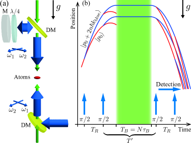
A schematic view of the experimental apparatus is shown in Fig. 1a. In brief, a blue 461 nm laser red detuned by GHz from the strong – transition is employed for inducing Bragg transitions. The Bragg laser source is similar to the one described in Mazzoni et al. (2015) with an output power of about 200 mW. The output is separated into two beams needed to drive the Bragg transitions, and their intensity and frequency are independently controlled by two acousto-optical modulators (AOMs) placed between the laser source and the atomic sample. The Bragg frequency detuning is set to be , where and are the driving radio frequencies (RF) of each AOM. The two beams are coupled into a polarization-maintaining fiber with mutually orthogonal polarizations; at the fiber output, a set of telescopes collimate the beam with a radius of 3 mm. The typical peak intensity is about mW/cm2 for each beam.
The Bragg laser beams are aligned from below onto the atomic sample, and the verticality of the beams is verified to within 1 mrad by means of a water surface reflection. The beams are then retro-reflected by a mirror positioned atop the system. The reflecting mirror is not vibration-isolated due to geometric limitations of the system. A quarter-wave plate is placed before the retro-reflecting mirror to rotate the polarizations of each reflected Bragg beam by 90°, forming two travelling waves in opposite directions with which to induce the Bragg transitions. Each order Bragg transition transfers to every atom, where is the wave-vector of the 461 nm Bragg laser.
The Bragg AOMs are driven by a two-channel RF generator, phase-locked to a 10 MHz Rubidium clock. The Bragg pulses are generated and shaped into Gaussian profiles by a second arbitrary-wave function generator mixed onto both channels of the first RF generator, which serves as a variable attenuator for the driving RF signals. In this text, pulse lengths are always given in terms of the corresponding Gaussian width . A phase modulated RF source is mixed with one channel of the first RF generator to provide a phase shift for the interferometer.
A second laser, superimposed onto the path of the blue Bragg laser, is used to provide the 1-D lattice for the Bloch evolution. The source laser for the lattice is a Coherent Verdi-V6 which delivers 6 W single mode radiation at 532 nm. The green laser output is split equally into two beams, with each beam passing through an AOM to stabilize the lattice intensity and to control the frequency difference between the two beams. The two lattice AOMs are driven by two RF synthesizers at MHz. Two PID controllers modulate the RF synthesizers for lattice intensity stabilization. A triggering signal with a time constant of about 230 s is summed onto the control signals for adiabatic loading of the atoms into the lattice. The two lattice beams are then each coupled into independent polarization-maintaining fibers. The two fiber outputs (about 1 W each) are collimated and sent from opposite directions to the atoms, with the same linear polarization. Both lattice beams share the same vertical path as the Bragg beams, onto which they are superimposed by means of two dichroic mirrors placed below and above the vacuum chamber. At the position of the atoms the waist of each beam is chosen to be 800 m, with a Rayleigh length of about 3 m. The lattice potential depth in this condition is about , where is the recoil energy of the green lattice, and the wave-vector.
III Experimental sequence
The cold atom preparation stage, as described in Mazzoni et al. (2015), results in about 88Sr atoms which are trapped and cooled down to K with a two-stage magneto-optical trap (MOT). The final radial (vertical) atomic distribution has a full width at half maximum (FWHM) of m (70 m).
About 10% of atoms are loaded directly from the MOT into the lattice in order to give them an initial vertical launch. During the loading, an additional cooling stage occurs by setting the second-stage-MOT laser frequency closer to resonance and by reducing the MOT beam intensity. This additional cooling stage reduces the losses due to initial evaporation of hot atoms loaded in the lattice and, as a result, there is an almost twofold increase in the number of atoms available for the interferometer. In these conditions, the atoms loaded in the lattice reach a temperature of nK, with a typical lifetime of about 1 s, limited mainly by the background vacuum.
Once loaded into the lattice, in order to do state preparation and to gain sufficient interferometer time, a vertical atom acceleration is achieved by chirping the frequency detuning between the two lattice beams from 0 kHz to 850 kHz with a constant rate of 10 kHz/ms, corresponding to a constant acceleration of 2.59 m/s2. The atomic cloud is then further elevated for 40 ms in a moving lattice with constant velocity of 0.22 m/s, to a height of about 0.9 cm above the MOT position. During this stage the atoms are adiabatically following the moving lattice in the first band; losses (about 20% of the initial population) are mainly due to Landau-Zener tunneling in the acceleration phase. At this point, the remaining atoms are released from the trap and a sequence of three first order Bragg pulses is applied, each with an increasing duration (9 s, 20 s and 40 s respectively). The last pulse ensures the required velocity selection for the interferometer, while the first two pulses are necessary to spatially separate the velocity selected atomic cloud from the residual atoms. The efficiency of the velocity selection is about 25%, leaving about atoms, with a typical vertical momentum width of . For Bragg interferometers a narrow selection of the atomic momentum is very important, not only for ensuring the high coherence of initial atomic wave packet (which is necessary for a high contrast interferometer signal Szigeti et al. (2012)), but also for independent detection of the different interferometer channels. In stark contrast to Raman inteferometers, the quantum interferometer states of a Bragg interferometer are encoded only onto the atoms’ external degrees of freedom, which are all detected by using standard on-resonance fluorescence/absorption detection. In this case, a narrow momentum distribution is important in order to separate the interferometer output signals after a reasonable time of flight.
The order Bragg diffraction has an effective Rabi frequency Giltner et al. (1995); Müller et al. (2008), where kHz is the recoil frequency for the chosen Bragg laser and is the two-photon Rabi frequency. In our experiment, the typical Rabi frequency of a first order Bragg diffraction is kHz for velocity selection pulses and kHz for each of the interferometer’s beam splitter pulses. The Fourier width of the beam splitter pulses is then sufficiently larger than the atomic momentum distribution, so most of the selected atoms are addressed for the interferometer. The pulse efficiency is 95% for first order Bragg transitions and 80% for second order transitions.
As shown in Fig. 1(b), the interferometer consists of two pairs of s long pulses separated by a time and a Bloch oscillation phase lasting for a time , where = 1.74 ms is the Bloch period and the number of Bloch oscillations. While the first pair of pulses are applied as the atomic cloud is travelling upward (immediately after the velocity-selective pulses), the two closing pairs are applied after the release from the lattice.
After the first pulse, the atomic wave packet is coherently split into two states, one with a vertical momentum of and the other with a vertical momentum of . The second pulse coherently splits each state again, resulting in four states, two with momentum and two with momentum . When the atoms in the higher momentum state reach the apogee, the green lattice beams are switched on over 230 s to adiabatically load the atoms into the first lattice band. Meanwhile, the atoms in the lower momentum state free-fall away and do not interfere with the trapped atoms (see Fig. 1b). The recapture efficiency of the atoms in the optical lattice after the free-flight period mostly depends on the free fall expansion of the atomic cloud after the launch that determines the final size of the cloud with respect to the lattice beam waist (and potential trap depth). In order to ensure a high recapture efficiency, the final launch velocity is set in order to limit the free-fall time between the second pulse and the switching-on of the lattice recapture to ms. With this choice, we typically obtain a recapture efficiency of %. The timing of the Bragg pulses is also critical in order to avoid double Bragg diffraction Giese et al. (2013); we set them to occur at least 5 ms away from the apogee time. Based on our launch and Bragg pulse timing parameters, the total time between two pulse pairs is ms .
At the end of the interferometer sequence, fluorescence detection is performed after 50 ms of time of flight (TOF). We employ a linearly polarized probe beam, resonant with the – transition, placed cm below the MOT position and retro-reflected to increase the intensity of the fluorescence signal. To improve selectivity of different momentum states, the probe beam is collimated into a sheet of light with a vertical (horizontal) width of about 200 m (2 mm).
IV Interferometer results
In this section, we focus on the interferometer results, especially the fringe contrast and its decay. The interferometer output is recorded by measuring the relative population of the momentum state over the sum population of both states and : . The interferometer fringes can be written as:
| (1) |
where P is a fringe offset and is the contrast. The phase for the trapped Ramsey-Bordé + Bloch interferometer is:
| (2) |
where is the order of the Bragg transitions involved and is the frequency chirping on the Bragg beams, used to compensate the Doppler shift seen by the atoms during the free-fall (typically set to a value of kHz/ms, for local gravity), while denotes the relative optical phase between -th Bragg pulse.
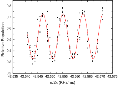
The trapped lattice phase will also induce an additional phase shift , with respect to a free-falling atom Cadoret et al. (2009); Charrière et al. (2012), where is the recoil velocity of the green lattice. However, in order to compensate for the Doppler shift after the trapped atoms are released from the lattice, the Bragg laser needs to jump a frequency rather than keeping a constant chirping rate for a free-falling frame, which means the phase shift term can be exactly cancelled. A demonstration of the interferometer for first order Bragg pulses () is shown as an example in Fig. 2, where the signal is showing the expected sinusoidal behaviour as a function of :
| (3) |
The velocity splitting by a first order Bragg pulse is 17 mm/s, which for an interferometer with ms results in a wave packet separation of 0.017 mm. For the same Ramsey time ms, we also measured the contrast evolution as a function of total Bloch oscillation time (see Fig. 3). For this measurement the interval time between each set of pulse pairs is ms . The contrast decay with is satisfactorily fitted with an exponential decay function with a time constant of ms. In this condition, we show that the interference can be preserved for a total number of Bloch oscillations in the green lattice.
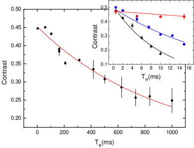
The fringe contrast of this lattice-trapped interferometer is an important feature because it limits the potential performances for future precision measurements of gravity and gravity gradients. For this reason, we also studied the contrast decay as a function of both parameters and . In a second set of measurements we fix the Bloch evolution time , and we recorded the contrast as a function of pulse separation time , as shown in the inset of Fig. 3.
Following the argument in Charrière et al. (2012), if we associate this decay to a random variation of the longitudinal velocity of the atomic wave packet during the interferometer, for a certain this induces a random phase shift of . Eventually, the contrast decay is given by the convolution of this random phase shift with the probability distribution of velocity variation :
| (4) |
where is the order of the Bragg transition. Applying this formula to the contrast observed as a function of in the inset of Fig. 3, for = 3.5 ms, 20.4 ms, 59.1 ms, the distribution function is nearly Lorentzian with a width 0.2 m/s, 1.6 m/s, and 3.6 m/s respectively, corresponding to very small momentum changes, less than , depending on .
V Decoherence sources
In this section we present a detailed analysis of different decoherence sources in our lattice-trapped interferometer. Most of the measurements focus on a precise determination of the atomic momentum distribution, a key property strongly affecting the final interferometer contrast Szigeti et al. (2012). It is important to notice that, as shown by the model in Eq. 4, it’s not only the initial momentum spread of the atoms which contributes to determining the maximum contrast achievable, but the momentum variation during the interferometer which can also crucially affect the final interferometer outcome. Since the system is not vibration isolated, a phase noise is present on the Bragg and lattice laser beams. However at the resolution of our measurements, this phase noise does not affect the momentum distribution nor the coherence length in the Bloch evolution stage, as we will show in this section.
To independently study the various decoherence sources taking place along the whole interferometer sequence, simpler interferometer schemes were studied, such as pure Ramsey-Bordé or Mach-Zehnder configurations, as well as measurements of the atomic momentum distribution during the various phases of the full trapped interferometer sequence.
V.1 Photon scattering
A first source of decoherence resulting in contrast losses comes from photon scattering events from off resonant blue and green light involved in the interferometer. Due to the large detuning of the 532 nm lattice light, we expect a negligible contribution to the interferometer contrast decay. Indeed, for a total light intensity of about 90 W/cm2 at 532 nm we estimate a photon scattering rate of s-1, allowing a long lattice trap lifetime and a long coherence time for the Bloch oscillation phase.
A more important contribution comes from the Bragg laser light at 461 nm. The Bragg laser is a semiconductor infrared source, which is amplified with a tapered amplifier and then frequency doubled into the blue part of the optical spectrum. Although the laser is frequency stabilized with a detuning of 10 GHz from – transition at 461 nm, the optical output spectrum of the tapered amplifier is several nm wide and the non-linear crystal employed for frequency doubling could also double some frequency components close to resonance. This could potentially cause additional amplified spontaneous emission (ASE) at a rate Andia et al. (2015).
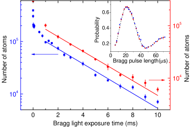
In order to avoid this additional resonance scattering, we filtered the laser light from the Bragg source with a 30 cm-long strontium heat-pipe operating at 400°C. At this temperature on-resonance light is absorbed by about 95% ( dB). Several tests were done (as shown in Fig. 4) to study the effect of spontaneous emission in our system, by keeping the Bragg laser 10 GHz detuned from the atomic transition with an intensity of 400 mW/cm2. Under these conditions, the estimated scattering rate for a pure monocromatic source, is Hz.
In a first test, we observed Rabi oscillations for an Bragg transition for different heat-pipe temperatures, ranging from C to C. As shown in the inset on Fig. 4 the Rabi oscillations taken at different heat-pipe temperatures are measured to be the same, from which we infer that during a Bragg pulse is negligible.
To confirm this, a second set of measurements of the lattice lifetime in presence of the Bragg beams, as a function of heat-pipe temperature, were taken. As shown by the data in Fig. 4, the lattice decay time constants do not depend on heat-pipe temperature, and the mean value ms is consistent with the previously estimated resonant scattering rate . This result is also confirmed by a third test, in which contrast measurements of a Mach-Zehnder interferometer have been repeated for the same temperature set. Also in this case the contrast observed is %, independent from heat-pipe temperature. Here, the contrast is mainly limited by Rabi frequency inhomogeneities that arise from a combined effect of atomic cloud expansion and imperfections on the profile of the Bragg beams Müller et al. (2008); McDonald et al. (2013). However, all additional decoherence processes during the trapped Bloch evolution phase will further decrease the value observed here in simple Ramsey-Bordé or Mach-Zehnder configurations.
V.2 Momentum distribution and lattice dynamics
Further characterization of the atomic wave packet evolution during the interferometer has been done in order to evidence small random velocity changes, predicted to be responsible for the loss of contrast.
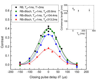
In a first set of measurements we evaluate the coherence length of the atomic sample for different interferometer sequences. This is done by measuring the interferometer contrast as a function of the time delay on the last recombining beam-splitter pulse. As the delay is increased, the fringe contrast decays because of the reduced wave packet overlapping at the recombination position. As a result, the typical contrast envelope as a function of the time delay is described by a Gaussian of the form Parazzoli et al. (2012):
| (5) |
which represents the convolution of free-space Gaussian wave packets with a coherence length , recombining at position , where is the recoil velocity for an -order Bragg transition.
It is important to notice that in a free-space interferometer it has been demonstrated that the coherence length is independent of the wave packet’s time evolution Kellogg et al. (2007). As a consequence, the coherence length depends only on the initial longitudinal velocity momentum distribution as given by the Heisenberg’s uncertainty principle. A similar approach has not yet been discussed for trapped configurations, so we performed a set of measurement to check whether the lattice might perturb the atomic coherence length. Fig. 5 shows the results of the contrast envelope measurements for different Bloch oscillation durations . As a reference, the contrast envelope for a pure Ramsey-Bordé interferometer is also reported. The data are fitted with Gaussian functions as in Eq. 5. The fitted coherence lengths are shown in the inset of Fig. 5 and the results (up to ms) are consistent within 1 with a mean value of nm. Since the coherence length is directly related to the velocity spread of the wave packets via , the resulting momentum spread is , a value consistent with independent measurements done through Bragg spectroscopy (see the next section). This analysis indicates that any changes in the momentum distribution introduced by the trapped interferometer phase is small and below the measurement sensitivity. In other words, the Bloch oscillation phase does not increase the longitudinal velocity distribution by an amount larger than previous estimation by the model in Eq. 4 with the observed contrast decay (see Fig. 3).
A similar result can be obtained independently from the direct measurement of the atomic momentum distribution during the various interferometer phases, and in particular after the Bloch oscillation phase. In this case, Bloch oscillations have been observed in TOF, and information on the atomic cloud’s longitudinal velocity distribution has been extracted. Fig. 6 shows the Bloch oscillations in the recaptured lattice up to 800 ms evolution time, together (bottom plot) with the estimated width of the atomic longitudinal velocity distribution. The data shows that during the Bloch evolution, the mean longitudinal velocity width does not change. The large standard deviations on distribution widths for longer evolution times arise mainly from fitting errors, which increase for smaller atomic number.

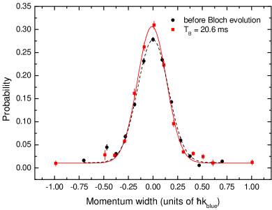
An even more sensitive technique employed for the estimation of the atomic cloud velocity distribution is Bragg spectroscopy. Here, Bragg spectra were recorded before the lattice recapture and after 20.6 ms Bloch evolution, as shown in Fig. 7. The Bragg pulse for spectroscopy has a Gaussian time profile with a duration of 150 s. The momentum resolution of this Bragg pulse is 0.02 . The fit of the two datasets gives a momentum width of 0.155(4) and 0.147(4) , before and after the Bloch oscillation phase respectively. Again, the difference between the two values is within the resolution of the Bragg spectroscopy itself, indicating that there is no process changing the momentum distribution during the Bloch evolution phase. The measured velocity distribution by TOF signal of Bloch oscillations is consistent with the one obtained by Bragg spectroscopy.
Again, the study of the lattice dynamics in terms of momentum spread confirms the same result: the interferometer contrast decay is mainly due to very small random changes in the atomic velocity that are well below the measurement resolution in all the experimental tests mentioned above.
V.3 Random momentum changes from lattice speckles
Despite being below our present level of measurement resolution, as shown in the previous section, we searched for possible cause of the small momentum changes in our interferometer other than photon scattering events. Especially during the long lattice phase, random momentum changes may arise from random lattice intensity gradients which, through dipole forces on the atoms, can impart a momentum perturbation to the interferometer and eventually cause a contrast loss.
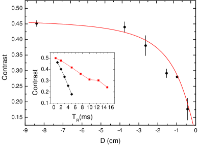
In particular, a speckle pattern arising from imperfections in some optical elements (especially the vacuum chamber windows) is the largest contributor to this effect. To show clearly how this effect can dramatically affect the interferometer, we performed a measurement of the contrast loss as a function of the distance between the trapped atoms and the top window of the vacuum chamber (the lattice beam waist was m for this measurement). In this case, the trapping position has been controlled by modifying the lattice elevation time. By classical geometrical consideration, the dipole force induced by speckles produced by the window scales as , therefore, given a fixed Bloch evolution time, we expect a similar dependence of the random velocity variation as a function of the distance . The result of the measurement is shown in Fig. 8. Here we numerically estimated the contrast decay with Eq. 4, with random velocity variation Charrière (2011), where is the potential depth variation due to speckle pattern and the dimension of the imperfection on the window. For our system 0.05 , m. The result of this model explains the contrast decay in Fig. 8 and gives an estimation of m/s for the atoms at the position of our typical experimental sequence (with cm and ms), consistent with the estimation obtained from the contrast decay as a function of in section III.
While in a typical experimental sequence the atoms are held sufficiently far from the top and bottom windows, the previous measurement shows clearly that any small intensity imperfection in the lattice profile can dramatically reduce the interferometer contrast. Far from the windows, the Gaussian beam profile depends strongly on the optical setup chosen to collimate the beam as well as on diffraction from apertures along the beam path. Furthermore, given a finite Rayleigh length (proportional to the square of the beam waist) of the lattice beams, it is also possible to have a coupling between the transverse and longitudinal motions in the lattice due to the wavefront curvature. One clear indication of this fact is shown by a measurement of the contrast decay as a function of the lattice beam waist. For this measurement we choose ms and we measured the contrast decay as a function of the Ramsey time for two different lattice beam waists, 300 m and m respectively. As shown in the inset of Fig 8, the contrast is improved by a factor of about (for a fixed value of ms), when the lattice beam waist at the atoms’ position is enlarged by a factor of .
The contrast decay is therefore strongly affected by the lattice beam profile and it can be improved dramatically by increasing the lattice size. From this evidence, we expect that a further increase of the lattice beam size or a better optical setup may improve our system. In the present experimental configuration this is not possible due to the limited lattice laser power at 532 nm. Another possible approach is using a resonant cavity for both the lattice and interferometer beams, so that the beam profile can be improved, and moreover high laser intensity can be achieved Hamilton et al. (2015).
VI Conclusions
In conclusion, we demonstrated a high contrast atom interferometer based on a combination of Ramsey-Bordé Bragg pulses and a Bloch oscillation stage in a vertical lattice. By using 88Sr atoms, the total interferometer time we reach is 1 s, currently limited by the atom lifetime in the lattice and geometry imperfections of the lattice beams. This limitation has been highlighted through a detailed experimental study of main decoherence sources in our system. In particular, a detailed study of the contrast decay sources as functions of the principal parameters (as the pulse separation time and the Bloch evolution time ) has been conducted.
As a result, we evidenced that at this level, decoherence is mainly given by technical and not fundamental limitations. For this reason, we think that trapped interferometer schemes employing Bloch oscillations with 88Sr atoms are valid candidates for further extending the total atom interferometer time, towards high precision inertial measurements.
A future prospect is to use a red laser at 689 nm to both drive the Bragg transitions and to trap the atoms in a standing wave lattice. Thanks to the narrow intercombination line and the high power available at this wavelength, it should be possible to realize larger trapping beams maintaining a sufficiently low photon scattering rate.
Acknowledgments
We thank Leonardo Salvi for help in the early stage of the experiment. We acknowledge financial support from INFN and the Italian Ministry of Education, University and Research (MIUR) under the Progetto Premiale “Interferometro Atomico”. We also acknowledge support from the European Union’s Seventh Framework Programme (FP7/2007-2013 grant agreement 250072 - “iSense” project and grant agreement 607493 - ITN “FACT” project).
References
- tin (2014) Atom interferometry, edited by G. M. Tino and M. A. Kasevich (Società Italiana di Fisica and IOS Press, Amsterdam, 2014).
- Gillot et al. (2013) J. Gillot, S. Lepoutre, A. Gauguet, M. Büchner, and J. Vigué, Phys. Rev. Lett. 111, 030401 (2013).
- Kovachy et al. (2015) T. Kovachy, P. Asenbaum, C. Overstreet, C. A. Donnelly, S. M. Dickerson, A. Sugarbaker, J. M. Hogan, and M. A. Kasevich, Nature (London) 528, 530 (2015).
- Lopes et al. (2015) R. Lopes, A. Imanaliev, A. Aspect, M. Cheneau, D. Boiron, and C. I. Westbrook, Nature (London) 520, 66 (2015).
- Manning et al. (2015) A. Manning, R. Khakimov, R. Dall, and A. Truscott, Nat. Phys 11, 539 (2015).
- Amelino-Camelia et al. (2009) G. Amelino-Camelia, C. Lämmerzahl, F. Mercati, and G. M. Tino, Phys. Rev. Lett. 103, 171302 (2009).
- Biedermann et al. (2015) G. W. Biedermann, X. Wu, L. Deslauriers, S. Roy, C. Mahadeswaraswamy, and M. A. Kasevich, Phys. Rev. A 91, 033629 (2015).
- Hartwig et al. (2015) J. Hartwig, S. Abend, C. Schubert, D. Schlippert, H. Ahlers, K. Posso-Trujillo, N. Gaaloul, W. Ertmer, and E. M. Rasel, New J. Phys 17, 035011 (2015).
- Zhou et al. (2015) L. Zhou, S.-T. Long, B. Tang, X. Chen, F. Gao, W.-C. Peng, W.-T. Duan, J.-Q. Zhong, Z.-Y. Xiong, J. Wang, Y.-Z. Zhang, and M.-S. Zhan, Phys. Rev. Lett. 115, 013004 (2015).
- Duan et al. (2016) X.-C. Duan, X.-B. Deng, M.-K. Zhou, K. Zhang, W.-J. Xu, F. Xiong, Y.-Y. Xu, C.-G. Shao, J. Luo, and Z.-K. Hu, Phys. Rev. Lett. 117, 023001 (2016).
- Bouchendira et al. (2011) R. Bouchendira, P. Cladé, S. Guellati-Khélifa, F. Nez, and F. Biraben, Phys. Rev. Lett. 106, 080801 (2011).
- Rosi et al. (2014) G. Rosi, F. Sorrentino, L. Cacciapuoti, M. Prevedelli, and G. M. Tino, Nature 510, 518 (2014).
- Tino and Vetrano (2007) G. M. Tino and F. Vetrano, Class. Quantum Grav 24, 2167 (2007).
- Dimopoulos et al. (2009) S. Dimopoulos, P. W. Graham, J. M. Hogan, M. A. Kasevich, and S. Rajendran, Phys. Lett. B 678, 37 (2009).
- Hohensee et al. (2011) M. Hohensee, S.-Y. Lan, R. Houtz, C. Chan, B. Estey, G. Kim, P.-C. Kuan, and H. Müller, Gen. Rel. Gravit 43, 1905 (2011).
- Graham et al. (2013) P. W. Graham, J. M. Hogan, M. A. Kasevich, and S. Rajendran, Phys. Rev. Lett. 110, 171102 (2013).
- Zhou et al. (2011) L. Zhou, Z.-Y. Xiong, W. Yang, B. Tang, W.-C. Peng, K. Hao, R.-B. Li, M. Liu, J. Wang, and M.-S. Zhan, Gen. Rel. Gravit 43, 1931 (2011).
- Mazzoni et al. (2015) T. Mazzoni, X. Zhang, R. Del Aguila, L. Salvi, N. Poli, and G. M. Tino, Phys. Rev. A 92, 053619 (2015).
- Jamison et al. (2014) A. O. Jamison, B. Plotkin-Swing, and S. Gupta, Phys. Rev. A 90, 063606 (2014).
- Poli et al. (2011) N. Poli, F.-Y. Wang, M. G. Tarallo, A. Alberti, M. Prevedelli, and G. M. Tino, Phys. Rev. Lett. 106, 038501 (2011).
- Tarallo et al. (2014) M. G. Tarallo, T. Mazzoni, N. Poli, D. V. Sutyrin, X. Zhang, and G. M. Tino, Phys. Rev. Lett. 113, 023005 (2014).
- McDonald et al. (2013) G. D. McDonald, H. Keal, P. A. Altin, J. E. Debs, S. Bennetts, C. C. N. Kuhn, K. S. Hardman, M. T. Johnsson, J. D. Close, and N. P. Robins, Phys. Rev. A 87, 013632 (2013).
- Charrière et al. (2012) R. Charrière, M. Cadoret, N. Zahzam, Y. Bidel, and A. Bresson, Phys. Rev. A 85, 013639 (2012).
- Andia et al. (2013) M. Andia, R. Jannin, F. Nez, F. Biraben, S. Guellati-Khélifa, and P. Cladé, Phys. Rev. A 88, 031605 (2013).
- Tarallo et al. (2012) M. G. Tarallo, A. Alberti, N. Poli, M. L. Chiofalo, F.-Y. Wang, and G. M. Tino, Phys. Rev. A 86, 033615 (2012).
- Szigeti et al. (2012) S. S. Szigeti, J. E. Debs, J. J. Hope, N. P. Robins, and J. D. Close, New J. Phys. 14, 023009 (2012).
- Giltner et al. (1995) D. M. Giltner, R. W. McGowan, and S. A. Lee, Phys. Rev. A 52, 3966 (1995).
- Müller et al. (2008) H. Müller, S.-w. Chiow, and S. Chu, Phys. Rev. A 77, 023609 (2008).
- Giese et al. (2013) E. Giese, A. Roura, G. Tackmann, E. M. Rasel, and W. P. Schleich, Phys. Rev. A 88, 053608 (2013).
- Cadoret et al. (2009) M. Cadoret, E. De Mirandes, P. Cladé, F. Nez, L. Julien, F. Biraben, and S. Guellati-Khélifa, Eur. Phys. J. Special Topics 172, 121 (2009).
- Andia et al. (2015) M. Andia, É. Wodey, F. Biraben, P. Cladé, and S. Guellati-Khélifa, J. Opt. Soc. Am. B 32, 1038 (2015).
- Parazzoli et al. (2012) L. P. Parazzoli, A. M. Hankin, and G. W. Biedermann, Phys. Rev. Lett. 109, 230401 (2012).
- Kellogg et al. (2007) J. R. Kellogg, N. Yu, J. M. Kohel, R. J. Thompson, D. C. Aveline, and L. Maleki, J. Mod. Opt 54, 2533 (2007).
- Charrière (2011) R. Charrière, Optimisation d’un capteur inertiel à atomes froids par une nouvelle technique de mesure accélérométrique combinant interférométrie atomique et oscillations de Bloch, Ph.D. thesis, Paris 6 (2011).
- Hamilton et al. (2015) P. Hamilton, M. Jaffe, J. M. Brown, L. Maisenbacher, B. Estey, and H. Müller, Phys. Rev. Lett. 114, 100405 (2015).