From active stresses and forces to self propulsion of droplets

R. Kree, P.S. Burada, and A. Zippelius Georg-August-Universität Göttingen, Institut für Theoretische Physik, Friedrich-Hund-Platz 1, 37077 Göttingen, Germany
Department of Physics, Indian Institute of Technology, Kharagpur – 721302, India
Abstract

We study the self-propulsion of spherical droplets as simplified hydrodynamic models of swimming microorganisms or artificial microswimmers. In contrast to approaches, which start from active velocity fields produced by the system, we consider active surface force or body force densities or active stresses as the origin of autonomous swimming. For negligible Reynolds number and given activity we first calculate the external and the internal flow fields as well as the center of mass velocity and an angular velocity of the droplet at fixed time. To construct trajectories from single time snapshots, the evolution of active forces or stresses must be determined in the laboratory frame. Here, we consider the case of active matter, which is carried by a continuously distributed, rigid but sparse (cyto)-sceleton that is immersed in the droplet’s interior. We calculate examples of trajectories of a droplet and its sceleton from force densities or stresses, which may be explicitely time dependent in a frame fixed within the sceleton.

I Introduction

Ever since the early work of Lighthill (1952) and others Blake (1971); Purcell (1952), the self-propulsion of microorganisms has attracted a lot of interest (Lighthill, 1976; Lauga and Powers, 2009, for reviews see). Over the last ten years or so, the activity increased enormously, partially motivated by the successful design of artificial swimmers Ebbens and Howse (2010). Both, biological as well as artificial swimmers have been studied extensively Lauga and Powers (2009), experimentally and with help of analytical modelling and simulation.

In the world of living microorganisms, there are many specific examples of self-propelled motion. One possibility are controlled shape changes of the organism as the cause of self-propulsion. These changes may either occur on the scale of the whole system, like in amoeboid or flagella-driven motion, or they may be confined to a thin boundary layer at the interface, like in ciliar motion of microorganisms. In the so called squirmer models, the small and periodic tangential shape changes of a quasi-continuous envelope of cilia drive a flow field close to the interface, which, after time-averaging, is modelled as a boundary condition for the velocity field at the interface Blake (1971). Some microorganisms, as for example the cyanobacterium Synechococcus or Myxobacteria do not even possess external organelles associated with motility, but seem to be driven by helical mechanical waves of the cell membrane Ehlers and Oster (2012); Nan et al. (2001).

On the other side, many artificial systems have been fabricated, allowing for high control of the mechanisms of self propulsion and the resulting dynamics of single swimmers as well as collective motion Bechinger2016. Common mechanisms are based on chemical reactions on the surface of the swimmer Golestanian et al. (2005); Takabatake et al. (2011); Peddireddy et al. (2012); Herminghaus et al. (2013) and more generally phoretic effects Golestanian et al. (2007); Herminghaus et al. (2013).

In addition, biomimetic devices have been assembled and analysed, such as solutions of cytoskeletal filaments and motors Sanchez et al. (2012); Köhler et al. (2011).

All the processes, which produce active flow and self-propulsion of microorganisms are controlled from the interior of the cell, in particular from the cytosceleton. Most frequently studied models, such as squirmer models, which use active flow boundary conditions at the interface, do not specify the forces inside the organism which provide a given squirming motion. On a molecular level, detailed knowledge about the molecular machinery is required to answer the question which forces inside the droplet provide a given squirming motion (or any other mechanism of self-propulsion). But on a mesoscopic, hydrodynamic level, the question may be answered in a more universal way. The internal mechanical properties of cells have been modelled as a material continuum Dembo and Harlow (1986), with a distribution of active force densities or stress tensors Joanny et al. (2007), which are produced by molecular motors and (dis)-assembly of semi-flexible polymers Loisel et al. (1999). A complete mesoscopic mechanical model of self-propulsion should consider the coupled evolution of active and passive matter and relate it to the motion of the whole cell and the generated flow fields in the interior of the cell and in the ambient fluid.

Here, we want to provide such a unified analytic framework, which links trajectories and flow fields of a swimmer to active forces. The swimmer is modeled as a droplet, consisting of two immiscible fluids. Activity is generated by one or several of the following causes: (i) active surface force densities (tractions) 𝐭actsuperscript𝐭𝑎𝑐𝑡\mathbf{t}^{act} on the interface Γ(t)Γ𝑡\Gamma(t) , (ii) active body force densities 𝐟actsuperscript𝐟𝑎𝑐𝑡\mathbf{f}^{act} or (iii) active stresses 𝝈actsuperscript𝝈𝑎𝑐𝑡\boldsymbol{\sigma}^{act} in the interior, K(t)𝐾𝑡K(t), of the droplet . Each of the active force distributions is the outcome of a molecular machinery, which we do not model in detail. Interface tractions may arise from the Marangoni effect, i.e. an inhomogeneous distribution of surfactants in ΓΓ\Gamma leading to inhomogeneous surface tension. Another machinery to generate surface tractions is made of molecular motors located at ΓΓ\Gamma, which drive short protrusions in the ambient fluid. These tractions only appear in the boundary conditions at ΓΓ\Gamma, which will be specified below. Internal active stresses emerge from a continuum description of short range molecular interactions (for example in the context of an active polar medium) inside the droplet and thus vanish outside of K(t)𝐾𝑡K(t) by definition. They may generate body force densities 𝐟act=𝝈actsuperscript𝐟𝑎𝑐𝑡superscript𝝈𝑎𝑐𝑡\mathbf{f}^{act}=-\nabla\cdot\boldsymbol{\sigma}^{act}, interface tractions 𝐞r𝝈act|Γevaluated-atsubscript𝐞𝑟superscript𝝈𝑎𝑐𝑡Γ-\mathbf{e}_{r}\cdot\boldsymbol{\sigma}^{act}|_{\Gamma} or both. An active body force density may, for example, be the result of a distribution of molecular motors driving objects (molecular paddles) in the droplet’s interior. To keep the coupled dynamics of internal material flows simple, we introduce rigid active matter, i.e. a rigid polymeric structure —modelling a (cyto)-sceleton — which we describe by a continuous density carrying active forces.

Surface tractions, active body forces or active stresses in the interior generate flow fields both outside and inside the droplet, which can indeed be observed Drescher et al. (105); Mustacich and Ware (1976). We compute these flow fields as well as the resulting trajectory of the droplet. Thus it becomes possible to infer, which actively generated internal flows or which active forces in a mechanical cortex near the interface may cause a given flow field and droplet motion in the ambient fluid, and vice versa. The analysis of general surface tractions also includes the Marangoni mechanism and the squirmer model as special cases. We discuss autonomous swimming which has to respect the constraints that total force and torque on the droplet vanish. Beyond autonomous swimming, we also analyse simple cases of the droplet‘s motion in external fields, such as sedimentation and buoyancy or optical traps.

The paper is organized as follows: In sec.II we introduce the model, specify the boundary conditions and set up the general solution strategy. In sec.III, we discuss flow fields of surface tractions, connect the force- and torque free case to the squirmer, and show that forces which can be derived from a potential are equivalent to given surface tractions. In sec.IV, we discuss a general class of active force densities in the interior of the droplet and in sec.V we consider the case of active stresses, which are generated by a polar medium. All calculations and results of sec. III-V refer to a single instant in time and therefore need no evolution equation of the active material. In sec.VI, we discuss the coupled dynamics of rigid active matter and internal flow and discuss some illustrating cases of emerging trajectories, before ending with conclusions and an outlook in sec.VII. Details of the calculations are delegated to Appendices.

II Model

Embedded within a Newtonian fluid consider a droplet of another viscous fluid, which at time t𝑡t occupies a finite region K(t)𝐾𝑡K(t) in 3-dimensional space. The two fluids differ in viscosity and are assumed to be incompressible and completely immiscible. Inside the droplet or located at its geometric boundary Γ(t)=K(t)Γ𝑡𝐾𝑡\Gamma(t)=\partial K(t) we assume active force densities, and we want to study, how they lead to self-propulsion of the droplet in a regime of negligible Reynolds number Happel and Brenner (1983); Kim and Karrila (2005). In a first step, we consider the forces as given. In a second step, which will be discussed in detail in sec. VI, we study the coupled dynamics of flow and active forces carried by a rigid (cyto)-sceleton within the droplet. We restrict the class of systems under study to spherical droplets (of fixed radius a𝑎a), which do not change their shape during time evolution. The field of normal unit vectors on ΓΓ\Gamma thus consists of radial unit vectors 𝐞rsubscript𝐞𝑟\mathbf{e}_{r} pointing into the ambient fluid.

At every fixed instant of time, the flow velocity fields 𝐯±superscript𝐯plus-or-minus\mathbf{v}^{\pm} inside (-) and outside (++) the droplet have to obey the Stokes equations in the laboratory frame (LF),

η±2𝐯±p±=𝝈±=𝐟act𝐟ext,𝐯±=0,formulae-sequencesuperscript𝜂plus-or-minussuperscript2superscript𝐯plus-or-minussuperscript𝑝plus-or-minussuperscript𝝈plus-or-minussuperscript𝐟𝑎𝑐𝑡superscript𝐟𝑒𝑥𝑡superscript𝐯plus-or-minus0\eta^{\pm}\nabla^{2}\mathbf{v}^{\pm}-\nabla p^{\pm}=\nabla\cdot\boldsymbol{\sigma}^{\pm}=-\mathbf{f}^{act}-\mathbf{f}^{ext},\quad\nabla\cdot\mathbf{v}^{\pm}=0, (1)

with viscosity η±superscript𝜂plus-or-minus\eta^{\pm} inside and outside the droplet. The flow fields 𝐯±superscript𝐯plus-or-minus\mathbf{v}^{\pm} create viscous stresses 𝝈±superscript𝝈plus-or-minus\boldsymbol{\sigma}^{\pm} with cartesian components σij±=p±δij+η±(jvi±+ivj±)subscriptsuperscript𝜎plus-or-minus𝑖𝑗superscript𝑝plus-or-minussubscript𝛿𝑖𝑗superscript𝜂plus-or-minussubscript𝑗subscriptsuperscript𝑣plus-or-minus𝑖subscript𝑖subscriptsuperscript𝑣plus-or-minus𝑗\sigma^{\pm}_{ij}=-p^{\pm}\delta_{ij}+\eta^{\pm}(\partial_{j}v^{\pm}_{i}+\partial_{i}v^{\pm}_{j}), where ivjsubscript𝑖subscript𝑣𝑗\partial_{i}v_{j} denotes the partial derivative vj/xisubscript𝑣𝑗subscript𝑥𝑖\partial v_{j}/\partial x_{i}. The pressure fields p±superscript𝑝plus-or-minusp^{\pm} are fixed by the incompressibility condition up to a constant. The active force density, 𝐟actsuperscript𝐟𝑎𝑐𝑡\mathbf{f}^{act}, vanishes outside of the droplet. We can either prescribe the force density or an active stress, which uniquely determines 𝐟act=𝝈actsuperscript𝐟𝑎𝑐𝑡superscript𝝈𝑎𝑐𝑡\mathbf{f}^{act}=-\nabla\cdot\boldsymbol{\sigma}^{act}. Note, however, that the reverse is not true. Generally it is not possible to calculate a unique stress from a body force density by solving 𝝈act=𝐟actsuperscript𝝈𝑎𝑐𝑡superscript𝐟𝑎𝑐𝑡-\nabla\cdot\boldsymbol{\sigma}^{act}=\mathbf{f}^{act} without any further information about the underlying molecular interactions. For the purposes of our general framework, we therefore treat the problems of given 𝐟actsuperscript𝐟𝑎𝑐𝑡\mathbf{f}^{act} and given 𝝈actsuperscript𝝈𝑎𝑐𝑡\boldsymbol{\sigma}^{act} separately.

To determine 𝐯±superscript𝐯plus-or-minus\mathbf{v}^{\pm} uniquely, the Stokes equations have to be supplemented by boundary conditions at the interface and at infinity. There are two boundary conditions at Γ(t)Γ𝑡\Gamma(t). First, we use the assumption that there is no velocity slip, i.e. the tangential velocity component is continuous across the interface. In combination with the condition of immiscibility, this leads to the continuity of 𝐯𝐯\mathbf{v} across Γ(t)Γ𝑡\Gamma(t),

𝐯+(𝐫+ϵ𝐞r)𝐯(𝐫ϵ𝐞r)=𝟎forϵ0,𝐫Γ(t)formulae-sequencesuperscript𝐯𝐫italic-ϵsubscript𝐞𝑟superscript𝐯𝐫italic-ϵsubscript𝐞𝑟0formulae-sequenceforitalic-ϵ0𝐫Γ𝑡\mathbf{v}^{+}(\mathbf{r}+\epsilon\mathbf{e}_{r})-\mathbf{v}^{-}(\mathbf{r}-\epsilon\mathbf{e}_{r})=\mathbf{0}\quad\text{for}\;\epsilon\to 0,\;\mathbf{r}\in\Gamma(t) (2)

The second boundary condition at Γ(t)Γ𝑡\Gamma(t) simply states that the interface is free, i.e. all forces acting on each area element must add up to zero. The viscous tractions 𝐭±=±𝐞r𝝈±superscript𝐭plus-or-minusplus-or-minussubscript𝐞𝑟superscript𝝈plus-or-minus\mathbf{t}^{\pm}=\pm\mathbf{e}_{r}\cdot\boldsymbol{\sigma}^{\pm}, which act on d2𝐒=d2S𝐞rsuperscript𝑑2𝐒superscript𝑑2𝑆subscript𝐞𝑟d^{2}\mathbf{S}=d^{2}S\,\mathbf{e}_{r} at the interface are balanced by a variety of forces, from which we separate a ubiquitous Laplace pressure term 𝐭L=γ0(𝐞r)𝐞r=(2γ0/a)𝐞rsubscript𝐭𝐿subscript𝛾0subscript𝐞𝑟subscript𝐞𝑟2subscript𝛾0𝑎subscript𝐞𝑟\mathbf{t}_{L}=-\gamma_{0}(\nabla\cdot\mathbf{e}_{r})\mathbf{e}_{r}=-(2\gamma_{0}/a)\mathbf{e}_{r} resulting from a homogeneous surface tension γ0subscript𝛾0\gamma_{0}, so that 𝐭++𝐭+𝐭L+𝐭a=0superscript𝐭superscript𝐭subscript𝐭𝐿subscript𝐭𝑎0\mathbf{t}^{+}+\mathbf{t}^{-}+\mathbf{t}_{L}+\mathbf{t}_{a}=0 on Γ(t)Γ𝑡\Gamma(t). If the active stress, 𝝈actsuperscript𝝈𝑎𝑐𝑡\boldsymbol{\sigma}^{act} is nonvanishing at the interface, it will also contribute to 𝐭asubscript𝐭𝑎\mathbf{t}_{a}. We separate this term explicitly and write 𝐭a=𝐞r𝝈act|Γ+𝐭actsubscript𝐭𝑎evaluated-atsubscript𝐞𝑟superscript𝝈𝑎𝑐𝑡Γsuperscript𝐭𝑎𝑐𝑡\mathbf{t}_{a}=-\mathbf{e}_{r}\cdot\boldsymbol{\sigma}^{act}|_{\Gamma}+{\mathbf{t}}^{act}. The boundary condition then takes on the form

𝐞r(𝝈+𝝈)=2γ0a𝐞r+𝐞r𝝈act𝐭actonΓ(t).subscript𝐞𝑟superscript𝝈superscript𝝈2subscript𝛾0𝑎subscript𝐞𝑟subscript𝐞𝑟superscript𝝈𝑎𝑐𝑡superscript𝐭𝑎𝑐𝑡onΓ𝑡\mathbf{e}_{r}\cdot(\boldsymbol{\sigma}^{+}-\boldsymbol{\sigma}^{-})=\frac{2\gamma_{0}}{a}\mathbf{e}_{r}+\mathbf{e}_{r}\cdot\boldsymbol{\sigma}^{act}-\mathbf{t}^{act}\quad\text{on}\;\Gamma(t). (3)

We do not consider any ambient background flow in LF; hence the velocity should vanish for |𝐫|𝐫|\mathbf{r}|\to\infty, and the total force acting on the surface of an infinitely large sphere should stay finite. This requires 𝐯+(𝐫)=𝒪(1/|𝐫|)superscript𝐯𝐫𝒪1𝐫\mathbf{v}^{+}(\mathbf{r})={\cal O}(1/|\mathbf{r}|) for |𝐫|𝐫|\mathbf{r}|\to\infty. The pressure is only determined up to a constant reference, which we fix by p+(𝐫)0superscript𝑝𝐫0p^{+}(\mathbf{r})\to 0 for |𝐫|𝐫|\mathbf{r}|\to\infty. For the autonomous swimmer one furthermore requires that it is force free, so that momentum is conserved. Therefore the momentum flux 𝐉+(r)=rd2S𝝈+𝐞rsuperscript𝐉𝑟subscript𝑟superscript𝑑2𝑆superscript𝝈subscript𝐞𝑟\mathbf{J}^{+}(r)=\int_{r}d^{2}S\;\boldsymbol{\sigma}^{+}\cdot\mathbf{e}_{r} through the surface of a sphere of radius r𝑟r vanishes for r𝑟{r\to\infty}. The viscous stresses thus have to vanish faster than r2superscript𝑟2r^{-2}, so that the flow velocity has to vanish faster than r1superscript𝑟1r^{-1}. This rules out the so called Stokeslet solutions with 𝐯+r1proportional-tosuperscript𝐯superscript𝑟1\mathbf{v}^{+}\propto r^{-1} for r𝑟{r\to\infty}. For active tractions and body forces, the requirement

𝐅=Vd2S𝐭act+V𝑑V𝐟act=0𝐅subscript𝑉superscript𝑑2𝑆superscript𝐭𝑎𝑐𝑡subscript𝑉differential-d𝑉superscript𝐟𝑎𝑐𝑡0\mathbf{F}=\int_{\partial V}d^{2}S\;\mathbf{t}^{act}+\int_{V}dV\;\mathbf{f}^{act}=0 (4)

constitutes an additional constraint. This constraint is fulfilled automatically, if 𝐟actsuperscript𝐟𝑎𝑐𝑡\mathbf{f}^{act} and 𝐭actsuperscript𝐭𝑎𝑐𝑡\mathbf{t}^{act} result from active stresses , because V𝑑V𝝈act=0subscript𝑉differential-d𝑉superscript𝝈𝑎𝑐𝑡0\int_{V}dV\,\nabla\cdot\boldsymbol{\sigma}^{act}=0 due to Gauss’ theorem for any V𝑉V enclosing the droplet.

Similar arguments hold for the torques. For autonomous swimmers, the total torque has to vanish, and the requirement

𝐍=Vd2S𝐫×𝐭act+V𝑑V𝐫×𝐟act=0𝐍subscript𝑉superscript𝑑2𝑆𝐫superscript𝐭𝑎𝑐𝑡subscript𝑉differential-d𝑉𝐫superscript𝐟𝑎𝑐𝑡0\mathbf{N}=\int_{\partial V}d^{2}S\;\mathbf{r}\times\mathbf{t}^{act}+\int_{V}dV\;\mathbf{r}\times\mathbf{f}^{act}=0 (5)

is an additional constraint on 𝐭actsuperscript𝐭𝑎𝑐𝑡\mathbf{t}^{act} and 𝐟actsuperscript𝐟𝑎𝑐𝑡\mathbf{f}^{act}. The torque generated by active stresses vanishes automatically, if 𝝈actsuperscript𝝈𝑎𝑐𝑡\boldsymbol{\sigma}^{act} is symmetric.

If additional external fields, such as buoyancy due to density mismatch, walls in a microfluidic device or optical traps are present, the total momentum is no longer conserved and the momentum sources or sinks resulting from external force densities 𝐟ext(𝐫,t)subscript𝐟𝑒𝑥𝑡𝐫𝑡\mathbf{f}_{ext}(\mathbf{r},t) have to be added to the above relations. These force densities are usually specified as functions in the laboratory frame.

The translational motion of the droplet is characterized by the velocity 𝐯CMsubscript𝐯𝐶𝑀\mathbf{v}_{CM} of its center of mass. For an incompressible flow vi=(vixj)/xisubscript𝑣𝑖subscript𝑣𝑖subscript𝑥𝑗subscript𝑥𝑖v_{i}=\partial(v_{i}x_{j})/\partial x_{i} and consequently, 𝐯CMsubscript𝐯𝐶𝑀\mathbf{v}_{CM} can alternatively be expressed as an integral over the interface,

𝐯CM(t)=34πa3K𝐯𝑑V=34πa2Γ(t)(𝐯±𝐞r)𝐞rd2S.subscript𝐯𝐶𝑀𝑡34𝜋superscript𝑎3subscript𝐾superscript𝐯differential-d𝑉34𝜋superscript𝑎2subscriptΓ𝑡superscript𝐯plus-or-minussubscript𝐞𝑟subscript𝐞𝑟superscript𝑑2𝑆\mathbf{v}_{CM}(t)=\frac{3}{4\pi a^{3}}\int_{K}\mathbf{v}^{-}\,dV=\frac{3}{4\pi a^{2}}\int_{\Gamma(t)}(\mathbf{v}^{\pm}\cdot\mathbf{e}_{r})\,\mathbf{e}_{r}d^{2}S. (6)

This equation simply expresses the fact that the total momentum of the droplet equals the velocity of its center of mass, multiplied by its total mass. An angular velocity may be defined analogously as the total angular momentum divided by the moment of inertia I=8πa5/15𝐼8𝜋superscript𝑎515I=8\pi a^{5}/15 of the homogeneous spherical droplet:

𝝎=1IK𝐫×𝐯𝑑V.𝝎1𝐼subscript𝐾𝐫superscript𝐯differential-d𝑉\boldsymbol{\omega}=\frac{1}{I}\int_{K}\mathbf{r}\times\mathbf{v}^{-}\,dV. (7)

The significance of 𝝎𝝎\boldsymbol{\omega} for the trajectories of the droplet will be discussed in Sec. VI.

Active tractions, body force densities and stresses will in general drive an active flow velocity field 𝐯actsubscript𝐯𝑎𝑐𝑡\mathbf{v}_{act} inside the droplet and on Γ(t)Γ𝑡\Gamma(t). This field provides the link between models based on force densities and models based on active velocities, in particular the envelope approximation of squirmer models. We will discuss this link in sec. III.2.

Our general strategy to study self-propulsion consists of two steps. First, the boundary value problem posed by eqs. (1, 2, 3) is solved at a fixed instant of time by expanding all quantities in terms of scalar or vector spherical harmonics, each characterized by a set of integer numbers 0<00\leq\ell<\infty and m𝑚-\ell\leq m\leq\ell. The definitions of the vector spherical harmonics and details of the solution procedure can be found in Appendix A. Stokes equations become a system of uncoupled ordinary differential equations for the mode amplitudes. Rigid body motions of the droplet are exclusively contained in the =11\ell=1 modes, which, for self-propelling droplets, contribute a term 𝒪(r3)𝒪superscript𝑟3\mathcal{O}(r^{-3}) to 𝐯+superscript𝐯\mathbf{v}^{+}. The leading contributions 𝐯+=𝒪(r2)superscript𝐯𝒪superscript𝑟2\mathbf{v}^{+}=\mathcal{O}(r^{-2}) for large r𝑟r emerge from =22\ell=2 modes, and some of the =33\ell=3 modes also decay as 𝒪(r3)𝒪superscript𝑟3\mathcal{O}(r^{-3}). Thus reduced descriptions of the force densities are sufficient, if one is only interested in the trajectories of the droplets and the far field of the accompanying flow. In the present work, we will focus on the droplet’s motion. Therefore, in a second step, we set up the temporal evolution of active forces and construct the common translational motion of the droplet and the rigid sceleton and the rotational motions of these two constituents.

III Activity generated by traction forces

In this section, we consider a droplet with given active tractions, 𝐭actsuperscript𝐭𝑎𝑐𝑡{\bf t}^{act} on its surface. It is our goal to compute the external, 𝐯+superscript𝐯{\bf v}^{+}, and internal, 𝐯superscript𝐯{\bf v}^{-}, flow fields as well as the center of mass velocity, 𝐯CMsubscript𝐯𝐶𝑀{\bf v}_{CM}, and the rotational velocity, 𝝎𝝎\boldsymbol{\omega}, of the droplet. We first consider general tractions, exerting a nonzero force and torque on the droplet. Subsequently, we specialise to the force- and torque-free case, i.e. discuss an autonomous swimmer which is propelled by surface tractions. We compare our results to the well studied squirmer with an active flow prescribed on the surface. The linear velocity as well as the external flow can be mapped onto each other, whereas the rotational velocity of the droplet driven by tractions vanishes. The droplet furthermore develops a characteristic flow pattern in the interior and energy is dissipated by both, the interior and exterior flow with the ratio of the two determined by the corresponding ratio of viscosities. We also show that external forces which can be derived from a potential, such as gravity, can be mapped onto tractions. The motion of the droplet with active tractions and external force is worked out.

III.1 General tractions

To determine the droplet’s trajectories we start from the =11\ell=1 modes of active tractions in the MMF at a fixed time t𝑡t, which we write as

𝐭(=1)act(θ,φ)=m=11(αmY1m(θ,φ)𝐞r+βmsY1m(θ,φ)+γm𝐞r×sY1m(θ,φ)).subscriptsuperscript𝐭𝑎𝑐𝑡1𝜃𝜑superscriptsubscript𝑚11subscript𝛼𝑚subscript𝑌1𝑚𝜃𝜑subscript𝐞𝑟subscript𝛽𝑚subscript𝑠subscript𝑌1𝑚𝜃𝜑subscript𝛾𝑚subscript𝐞𝑟subscript𝑠subscript𝑌1𝑚𝜃𝜑\mathbf{t}^{act}_{(\ell=1)}(\theta,\varphi)=\sum_{m=-1}^{1}\big{(}\alpha_{m}Y_{1m}(\theta,\varphi)\mathbf{e}_{r}+\beta_{m}{\bf\nabla}_{s}Y_{1m}(\theta,\varphi)+\gamma_{m}{\bf e}_{r}\times{\bf\nabla}_{s}Y_{1m}(\theta,\varphi)\big{)}. (8)

Here s=rsubscript𝑠𝑟\nabla_{s}=r\nabla denotes the angular part of the gradient operator. We solve Stokes equations with the boundary conditions of Eqs.(2,3) in the interior and exterior region of the droplet and find for the velocity fields in the lab frame

𝐯+(𝐫)=m((am+ar+bm+a3r3)Y1m(θ,φ)𝐞r+(am+arbm+a3r3)12sY1m(θ,φ)+cm+a2r2𝐞r×sY1m(θ,φ)),superscript𝐯𝐫subscript𝑚superscriptsubscript𝑎𝑚𝑎𝑟superscriptsubscript𝑏𝑚superscript𝑎3superscript𝑟3subscript𝑌1𝑚𝜃𝜑subscript𝐞𝑟superscriptsubscript𝑎𝑚𝑎𝑟superscriptsubscript𝑏𝑚superscript𝑎3superscript𝑟312subscript𝑠subscript𝑌1𝑚𝜃𝜑superscriptsubscript𝑐𝑚superscript𝑎2superscript𝑟2subscript𝐞𝑟subscript𝑠subscript𝑌1𝑚𝜃𝜑{\bf v}^{+}({\bf r})=\sum_{m}\big{(}(a_{m}^{+}\frac{a}{r}+b_{m}^{+}\frac{a^{3}}{r^{3}})Y_{1m}(\theta,\varphi)\mathbf{e}_{r}+(a_{m}^{+}\frac{a}{r}-b_{m}^{+}\frac{a^{3}}{r^{3}})\frac{1}{2}{\bf\nabla}_{s}Y_{1m}(\theta,\varphi)+c_{m}^{+}\frac{a^{2}}{r^{2}}\mathbf{e}_{r}\times{\bf\nabla}_{s}Y_{1m}(\theta,\varphi)\big{)},
𝐯(𝐫)=m((amr2a2+bm)Y1m(θ,φ)𝐞r+(2amr2a2+bm)sY1m(θ,φ)+cmra𝐞r×sY1m(θ,φ)).superscript𝐯𝐫subscript𝑚superscriptsubscript𝑎𝑚superscript𝑟2superscript𝑎2superscriptsubscript𝑏𝑚subscript𝑌1𝑚𝜃𝜑subscript𝐞𝑟2superscriptsubscript𝑎𝑚superscript𝑟2superscript𝑎2superscriptsubscript𝑏𝑚subscript𝑠subscript𝑌1𝑚𝜃𝜑superscriptsubscript𝑐𝑚𝑟𝑎subscript𝐞𝑟subscript𝑠subscript𝑌1𝑚𝜃𝜑{\bf v}^{-}({\bf r})=\sum_{m}\big{(}(a_{m}^{-}\frac{r^{2}}{a^{2}}+b_{m}^{-})Y_{1m}(\theta,\varphi)\mathbf{e}_{r}+(2a_{m}^{-}\frac{r^{2}}{a^{2}}+b_{m}^{-}){\bf\nabla}_{s}Y_{1m}(\theta,\varphi)+c_{m}^{-}\frac{r}{a}\mathbf{e}_{r}\times{\bf\nabla}_{s}Y_{1m}(\theta,\varphi)\big{)}. (9)

where the expansion coefficients are given in terms of the traction forces as follows:

am+superscriptsubscript𝑎𝑚\displaystyle a_{m}^{+} =\displaystyle= a3η+(αm+2βm)𝑎3superscript𝜂subscript𝛼𝑚2subscript𝛽𝑚\displaystyle\frac{a}{3\eta^{+}}(\alpha_{m}+2\beta_{m}) (10)
bm+superscriptsubscript𝑏𝑚\displaystyle b_{m}^{+} =\displaystyle= a3η+λαm+2(λ+1)βm2+3λ𝑎3superscript𝜂𝜆subscript𝛼𝑚2𝜆1subscript𝛽𝑚23𝜆\displaystyle-\frac{a}{3\eta^{+}}\frac{\lambda\alpha_{m}+2(\lambda+1)\beta_{m}}{2+3\lambda} (11)
amsuperscriptsubscript𝑎𝑚\displaystyle a_{m}^{-} =\displaystyle= a3η+αmβm2+3λ𝑎3superscript𝜂subscript𝛼𝑚subscript𝛽𝑚23𝜆\displaystyle-\frac{a}{3\eta^{+}}\frac{\alpha_{m}-\beta_{m}}{2+3\lambda} (12)
bmsuperscriptsubscript𝑏𝑚\displaystyle b_{m}^{-} =\displaystyle= a3η+(3+2λ)αm+(4λ+1)βm2+3λ𝑎3superscript𝜂32𝜆subscript𝛼𝑚4𝜆1subscript𝛽𝑚23𝜆\displaystyle-\frac{a}{3\eta^{+}}\frac{(3+2\lambda)\alpha_{m}+(4\lambda+1)\beta_{m}}{2+3\lambda} (13)
cm+superscriptsubscript𝑐𝑚\displaystyle c_{m}^{+} =\displaystyle= cm=aγm3η+superscriptsubscript𝑐𝑚𝑎subscript𝛾𝑚3superscript𝜂\displaystyle c_{m}^{-}=\frac{a\gamma_{m}}{3\eta^{+}} (14)

Here the ratio of interior to exterior viscosity has been denoted by λ=η/η+𝜆superscript𝜂superscript𝜂\lambda=\eta^{-}/\eta^{+}.

The above equations decouple into two sets of equations. The first one corresponds to tractions with γm=0subscript𝛾𝑚0\gamma_{m}=0 that give rise to a linear velocity of the droplet but no rotational velocity. The center of mass velocity is determined by the flow field according to Eqs.6. Straightforward computation yields

𝐯CM=34πh0𝐞z32πRe(h1)𝐞x+32πIm(h1)𝐞ysubscript𝐯𝐶𝑀34𝜋subscript0subscript𝐞𝑧32𝜋Resubscript1subscript𝐞𝑥32𝜋Imsubscript1subscript𝐞𝑦\mathbf{v}_{CM}=\sqrt{\frac{3}{4\pi}}h_{0}\mathbf{e}_{z}-\sqrt{\frac{3}{2\pi}}\mathrm{Re\,}(h_{1})\mathbf{e}_{x}+\sqrt{\frac{3}{2\pi}}\mathrm{Im\,}(h_{1})\mathbf{e}_{y}\\ (15)

with

hm=2a3η+αm(1+λ)+βm(1+2λ)2+3λsubscript𝑚2𝑎3superscript𝜂subscript𝛼𝑚1𝜆subscript𝛽𝑚12𝜆23𝜆h_{m}=\frac{2a}{3\eta^{+}}\frac{\alpha_{m}(1+\lambda)+\beta_{m}(1+2\lambda)}{2+3\lambda} (16)

Such tractions can for example be generated by Marangoni flow, which is represented by an inhomogeneous surface tension Γ(θ,φ)Γ𝜃𝜑\Gamma(\theta,\varphi). For this example the tractions are given by

a𝐭act(θ,φ)=2Γ(θ,φ)𝐞r+sΓ(θ,φ),𝑎superscript𝐭𝑎𝑐𝑡𝜃𝜑2Γ𝜃𝜑subscript𝐞𝑟subscript𝑠Γ𝜃𝜑a\mathbf{t}^{act}(\theta,\varphi)=2\Gamma(\theta,\varphi)\mathbf{e}_{r}+{\bf\nabla}_{s}\Gamma(\theta,\varphi), (17)

and hence cannot give rise to a rotational velocity of the droplet.

The second class of tractions has only γm0subscript𝛾𝑚0\gamma_{m}\neq 0. The internal flow, as given in Eq.9, corresponds to rigid body rotation

𝐯(𝐫)=mcmra𝐞r×sY1m(θ,φ)=𝝎×𝐫superscript𝐯𝐫subscript𝑚superscriptsubscript𝑐𝑚𝑟𝑎subscript𝐞𝑟subscript𝑠subscript𝑌1𝑚𝜃𝜑𝝎𝐫{\bf v}^{-}({\bf r})=\sum_{m}c_{m}^{-}\frac{r}{a}\mathbf{e}_{r}\times{\bf\nabla}_{s}Y_{1m}(\theta,\varphi)={\boldsymbol{\omega}}\times{\bf r} (18)

with the rotational velocity given by

𝝎=13η+32π(Re(γ1)𝐞xIm(γ1)𝐞yγ02𝐞z)𝝎13superscript𝜂32𝜋Resubscript𝛾1subscript𝐞𝑥Imsubscript𝛾1subscript𝐞𝑦subscript𝛾02subscript𝐞𝑧\boldsymbol{\omega}=\frac{1}{3\eta^{+}}\sqrt{\frac{3}{2\pi}}\big{(}{\mathrm{Re\,}}(\gamma_{1})\mathbf{e}_{x}-{\mathrm{Im\,}(\gamma_{1})}\mathbf{e}_{y}-\frac{\gamma_{0}}{\sqrt{2}}\mathbf{e}_{z}\big{)} (19)

The total force 𝐅𝐅\mathbf{F} and torque 𝐍𝐍\mathbf{N} on the droplet can be computed from

𝐅=Γ(t)d2S𝐭act,𝐍=Γ(t)d2S𝐫×𝐭actformulae-sequence𝐅subscriptΓ𝑡superscript𝑑2𝑆subscript𝐭𝑎𝑐𝑡𝐍subscriptΓ𝑡superscript𝑑2𝑆𝐫subscript𝐭𝑎𝑐𝑡\mathbf{F}=\int_{\Gamma(t)}d^{2}S\;\mathbf{t}_{act},\qquad\mathbf{N}=\int_{\Gamma(t)}d^{2}S\;\mathbf{r}\times\mathbf{t}_{act} (20)

and hence are independent of λ𝜆\lambda. We find

𝐅/a2𝐅superscript𝑎2\displaystyle\mathbf{F}/a^{2} =\displaystyle= 4π3(α0+2β0)𝐞z+8π3Re(α1+2β1)𝐞x8π3Im(α1+2β1)𝐞y4𝜋3subscript𝛼02subscript𝛽0subscript𝐞𝑧8𝜋3Resubscript𝛼12subscript𝛽1subscript𝐞𝑥8𝜋3Imsubscript𝛼12subscript𝛽1subscript𝐞𝑦\displaystyle\sqrt{\frac{4\pi}{3}}(\alpha_{0}+2\beta_{0})\mathbf{e}_{z}+\sqrt{\frac{8\pi}{3}}\mathrm{Re\,}(\alpha_{1}+2\beta_{1})\mathbf{e}_{x}-\sqrt{\frac{8\pi}{3}}\mathrm{Im\,}(\alpha_{1}+2\beta_{1})\mathbf{e}_{y} (21)
𝐍/a3𝐍superscript𝑎3\displaystyle\mathbf{N}/a^{3} =\displaystyle= 4π32γ0𝐞z+8π32Re(γ1)𝐞x8π32Im(γ1)𝐞y=8πη+𝝎4𝜋32subscript𝛾0subscript𝐞𝑧8𝜋32Resubscript𝛾1subscript𝐞𝑥8𝜋32Imsubscript𝛾1subscript𝐞𝑦8𝜋superscript𝜂𝝎\displaystyle-\sqrt{\frac{4\pi}{3}}2\gamma_{0}\mathbf{e}_{z}+\sqrt{\frac{8\pi}{3}}2\mathrm{Re\,}(\gamma_{1})\mathbf{e}_{x}-\sqrt{\frac{8\pi}{3}}2\mathrm{Im\,}(\gamma_{1})\mathbf{e}_{y}=8\pi\eta^{+}{\boldsymbol{\omega}} (22)

III.2 Force and torque free case

In this section we discuss the special case that no external force and no external torque are present as required for an autonomous swimmer. We first work out the consequences for self propulsion by tractions and then compare our results to the squirmer model in which an active velocity on the surface of a particle is described. The squirmer model has been discussed extensively in the literature, mainly for a solid particle.

Vanishing of the torque (Eq.22) implies that all γm=0subscript𝛾𝑚0\gamma_{m}=0 and hence the angular velocity vanishes. In other words, tractions cannot generate rotational motion of an autonomous swimmer. Vanishing of the total force (Eq.21) implies a restriction on the traction forces, namely αm=2βmsubscript𝛼𝑚2subscript𝛽𝑚\alpha_{m}=-2\beta_{m}. Consequently the Stokeslet vanishes, i.e. am+=0superscriptsubscript𝑎𝑚0a_{m}^{+}=0, and the exterior flow field with =11\ell=1 decays as 1/r31superscript𝑟31/r^{3}.

The flow fields outside and inside of the force-free droplet are given by

𝐯+(𝐫)superscript𝐯𝐫\displaystyle\mathbf{v}^{+}(\mathbf{r}) =\displaystyle= 2a3η+(2+3λ)m=11βma3r3(Y1m𝐞r12sY1m)2𝑎3superscript𝜂23𝜆superscriptsubscript𝑚11subscript𝛽𝑚superscript𝑎3superscript𝑟3subscript𝑌1𝑚subscript𝐞𝑟12subscript𝑠subscript𝑌1𝑚\displaystyle-\frac{2a}{3\eta^{+}(2+3\lambda)}\sum_{m=-1}^{1}\beta_{m}\frac{a^{3}}{r^{3}}\big{(}Y_{1m}\mathbf{e}_{r}-\frac{1}{2}\nabla_{s}Y_{1m}\big{)}
𝐯(𝐫)superscript𝐯𝐫\displaystyle\mathbf{v}^{-}(\mathbf{r}) =\displaystyle= a3η+(2+3λ)m=11βm((53r2a2)Y1m𝐞r+(56r2a2)12sY1m)𝑎3superscript𝜂23𝜆superscriptsubscript𝑚11subscript𝛽𝑚53superscript𝑟2superscript𝑎2subscript𝑌1𝑚subscript𝐞𝑟56superscript𝑟2superscript𝑎212subscript𝑠subscript𝑌1𝑚\displaystyle-\frac{a}{3\eta^{+}(2+3\lambda)}\sum_{m=-1}^{1}\beta_{m}\Big{(}(5-3\frac{r^{2}}{a^{2}})Y_{1m}\mathbf{e}_{r}+(5-6\frac{r^{2}}{a^{2}})\frac{1}{2}\nabla_{s}Y_{1m}\Big{)}

and the center of mass velocity follows from Eqs.15,16 or directly from the constant part of the velocity field in the interior of the droplet:

𝐯CM=a3π(2η++3η)(β0𝐞z2Reβ1𝐞x+2Imβ1𝐞y)subscript𝐯𝐶𝑀𝑎3𝜋2superscript𝜂3superscript𝜂subscript𝛽0subscript𝐞𝑧2Resubscript𝛽1subscript𝐞𝑥2Imsubscript𝛽1subscript𝐞𝑦\mathbf{v}_{CM}=-\frac{a}{\sqrt{3\pi}(2\eta^{+}+3\eta^{-})}\Big{(}\beta_{0}\mathbf{e}_{z}-\sqrt{2}\mathrm{Re\,}\beta_{1}\mathbf{e}_{x}+\sqrt{2}\mathrm{Im\,}\beta_{1}\mathbf{e}_{y}\Big{)} (23)

Instead of considering the force-free droplet, one can ask what is the force needed to keep the active droplet at rest in the LF? We now set 𝐯CM=0subscript𝐯𝐶𝑀0\mathbf{v}_{CM}=0 and compute the stall force ,

𝐅stall=Γ(t)(𝝈+𝐧)d2S.subscript𝐅𝑠𝑡𝑎𝑙𝑙subscriptΓ𝑡superscript𝝈𝐧superscript𝑑2𝑆{\bf F}_{stall}=\int_{\Gamma(t)}(\boldsymbol{\sigma}^{+}\cdot\mathbf{n})d^{2}S. (24)

As one would expect the stall force is proportional to 𝐯CMsubscript𝐯𝐶𝑀\mathbf{v}_{CM}

𝐅stall=μ𝐯CMwithμ=(1+λ)2πa(2η++3η)formulae-sequencesubscript𝐅𝑠𝑡𝑎𝑙𝑙𝜇subscript𝐯𝐶𝑀with𝜇1𝜆2𝜋𝑎2superscript𝜂3superscript𝜂{\bf F}_{stall}=-\mu\mathbf{v}_{CM}\quad\mbox{with}\quad\mu=\frac{(1+\lambda)}{2\pi a(2\eta^{+}+3\eta^{-})} (25)

The mobility μ𝜇\mu is seen to depend on both - the interior and exterior viscosities. This reflects the fact that traction forces generate active surface velocities which depend on both viscosities. In the limit that the fluid in the interior becomes highly viscous or even solid-like (limηsuperscript𝜂\lim\eta^{-}\to\infty), the mobility reduces to the one for a solid particle: μ=16πaη+𝜇16𝜋𝑎superscript𝜂\mu=\frac{1}{6\pi a\eta^{+}}. In the opposite limit limη0superscript𝜂0\lim\eta^{-}\to 0, we recover the mobility of a gas bubble: μ=14πaη+𝜇14𝜋𝑎superscript𝜂\mu=\frac{1}{4\pi a\eta^{+}}. In between the mobility increases monotonically.

We now compare our results to the squirmer model which prescribes the active velocity field on the surface of the sphere Blake (1971):

𝐯act(θ,φ)=m=11(ρmsY1m(θ,φ))subscript𝐯𝑎𝑐𝑡𝜃𝜑superscriptsubscript𝑚11subscript𝜌𝑚subscript𝑠subscript𝑌1𝑚𝜃𝜑\mathbf{v}_{act}(\theta,\varphi)=\sum_{m=-1}^{1}\big{(}\rho_{m}\nabla_{s}Y_{1m}(\theta,\varphi)\big{)} (26)

There is no radial component to the active velocity, because we require shape and size of the droplet to be preserved. The exterior and interior flow field 𝐯±(r,θ,φ)superscript𝐯plus-or-minus𝑟𝜃𝜑\mathbf{v}^{\pm}(r,\theta,\varphi) have to fulfill the following boundary condition in the LF:

𝐯+(𝐫)=𝐯(𝐫)=𝐯CM+𝐯act(𝐫)for𝐫Γ(t).formulae-sequencesuperscript𝐯𝐫superscript𝐯𝐫subscript𝐯𝐶𝑀subscript𝐯𝑎𝑐𝑡𝐫for𝐫Γ𝑡\mathbf{v}^{+}(\mathbf{r})=\mathbf{v}^{-}(\mathbf{r})=\mathbf{v}_{CM}+\mathbf{v}_{act}(\mathbf{r})\quad\text{for}\;\mathbf{r}\in\Gamma(t). (27)

The center of mass velocity is yet unknown and has to be determined from the vanishing of the total force (see Eq.20). Solving Stokes equation for 𝐯±superscript𝐯plus-or-minus\mathbf{v}^{\pm} with the above boundary condition and the requirement of vanishing total force, we find for the center of mass velocity

𝐯CM=23π(ρ02𝐞z+Reρ1𝐞xImρ1𝐞y)subscript𝐯𝐶𝑀23𝜋subscript𝜌02subscript𝐞𝑧Resubscript𝜌1subscript𝐞𝑥Imsubscript𝜌1subscript𝐞𝑦\mathbf{v}_{CM}=\sqrt{\frac{2}{3\pi}}\big{(}-\frac{\rho_{0}}{\sqrt{2}}\mathbf{e}_{z}+\mathrm{Re\,}\rho_{1}\mathbf{e}_{x}-\mathrm{Im\,}\rho_{1}\mathbf{e}_{y}\big{)} (28)

The two approaches yield the same 𝐯CMsubscript𝐯𝐶𝑀\mathbf{v}_{CM}, if we identify the coefficients of the active tractions with those of the active velocity according to

ρm=aβm2η++3ηsubscript𝜌𝑚𝑎subscript𝛽𝑚2superscript𝜂3superscript𝜂\rho_{m}=\frac{a\beta_{m}}{2\eta^{+}+3\eta^{-}} (29)

The rotational motion of the squirmer has been discussed by Pak and LaugaPak and Lauga (2014) and more recently by Pedley et al. (2016). Only the l=1𝑙1l=1 component of the active velocity contributes to the rotational velocity of the squirmer and is equivalent to a rigid rotation of the surface with angular velocity 𝝎𝝎\boldsymbol{\omega}, i.e. 𝐯act(θ,φ)=a𝝎×𝐞rsubscript𝐯𝑎𝑐𝑡𝜃𝜑𝑎𝝎subscript𝐞𝑟\mathbf{v}_{act}(\theta,\varphi)=a\boldsymbol{\omega}\times{\bf e}_{r} The active velocity gives rise to a rotation in the LF frame which exactly cancels the above rotational component of 𝐯act(θ,φ)subscript𝐯𝑎𝑐𝑡𝜃𝜑\mathbf{v}_{act}(\theta,\varphi) so that the l=1𝑙1l=1 components of the external and internal flow field are not affected. Rotational components with l>1𝑙1l>1 in 𝐯actsubscript𝐯𝑎𝑐𝑡\mathbf{v}_{act} do modify the flow fields inside and outside the droplet, but do not contribute to 𝝎𝝎\boldsymbol{\omega}.

III.3 Energy Dissipation

Energy is dissipated by both, the exterior and the interior flow:

tE±=V±d3xσik±kvi±=±Vd2xvi±σik±nksubscript𝑡superscript𝐸plus-or-minussubscriptsuperscript𝑉plus-or-minussuperscript𝑑3𝑥superscriptsubscript𝜎𝑖𝑘plus-or-minussubscript𝑘superscriptsubscript𝑣𝑖plus-or-minusplus-or-minussubscript𝑉superscript𝑑2𝑥superscriptsubscript𝑣𝑖plus-or-minussuperscriptsubscript𝜎𝑖𝑘plus-or-minussubscript𝑛𝑘\partial_{t}E^{\pm}=\int_{V^{\pm}}d^{3}x\sigma_{ik}^{\pm}\partial_{k}v_{i}^{\pm}=\pm\int_{\partial V}d^{2}x\;v_{i}^{\pm}\sigma_{ik}^{\pm}\;n_{k} (30)

where we have used that kσik±=0subscript𝑘superscriptsubscript𝜎𝑖𝑘plus-or-minus0\partial_{k}\sigma_{ik}^{\pm}=0 and the normal is always defined as pointing outward of the sphere. The second inequality in the above equation just says that the energy dissipated in the volumes V±superscript𝑉plus-or-minusV^{\pm} is balanced by the energy inflow from the boundary. The latter is more easily computed and we obtain for the force free case

tE+subscript𝑡superscript𝐸\displaystyle\partial_{t}E^{+} =\displaystyle= 4η+a2(2η++3η)2(β02+2|β1|2)4superscript𝜂superscript𝑎2superscript2superscript𝜂3superscript𝜂2superscriptsubscript𝛽022superscriptsubscript𝛽12\displaystyle-\frac{4\eta^{+}a^{2}}{(2\eta^{+}+3\eta^{-})^{2}}(\beta_{0}^{2}+2|\beta_{1}|^{2}) (31)
tEsubscript𝑡superscript𝐸\displaystyle\partial_{t}E^{-} =\displaystyle= 6ηa2(2η++3η)2(β02+2|β1|2)6superscript𝜂superscript𝑎2superscript2superscript𝜂3superscript𝜂2superscriptsubscript𝛽022superscriptsubscript𝛽12\displaystyle-\frac{6\eta^{-}a^{2}}{(2\eta^{+}+3\eta^{-})^{2}}(\beta_{0}^{2}+2|\beta_{1}|^{2}) (32)

so that the ratio is independent of the driving amplitudes {βm}subscript𝛽𝑚\{\beta_{m}\}:

tE+/tE=2η+3ηsubscript𝑡superscript𝐸subscript𝑡superscript𝐸2superscript𝜂3superscript𝜂\partial_{t}E^{+}/\partial_{t}E^{-}=\frac{2\eta^{+}}{3\eta^{-}} (33)

In the stationary state the total dissipation is balanced by the energy input due to surface tractions: tE++tE=tEact=Vd2xtiactvisubscript𝑡superscript𝐸subscript𝑡superscript𝐸subscript𝑡superscript𝐸𝑎𝑐𝑡subscript𝑉superscript𝑑2𝑥superscriptsubscript𝑡𝑖𝑎𝑐𝑡subscript𝑣𝑖\partial_{t}E^{+}+\partial_{t}E^{-}=\partial_{t}E^{act}=\int_{\partial V}d^{2}x\;t_{i}^{act}v_{i}.

III.4 Sedimenting Active Droplets

We only consider the simplest case, namely a passive droplet in an external potential, which is assumed to be continuous across the interface. For example, if the fluids are not density matched, then buoyancy forces act on the droplet. These can be represented by a potential U=Δρg(za)𝑈Δ𝜌𝑔𝑧𝑎U=\Delta\rho g(z-a) for za𝑧𝑎z\leq a, where ΔρΔ𝜌\Delta\rho denotes the difference in density between the inside and outside fluids.

In the general case, the potential is expanded in spherical harmonics U=const.+mUm(r)Y1mformulae-sequence𝑈𝑐𝑜𝑛𝑠𝑡subscript𝑚subscript𝑈𝑚𝑟subscript𝑌1𝑚U=const.+\sum_{m}U_{m}(r)Y_{1m}, keeping only l=1𝑙1l=1. In the interior of the droplet, we then have to solve Stokes equation

η2𝐯=p𝐟extsuperscript𝜂superscript2superscript𝐯superscript𝑝subscript𝐟𝑒𝑥𝑡\eta^{-}\nabla^{2}\mathbf{v}^{-}=\nabla p^{-}-\mathbf{f}_{ext} (34)

in the presence of an external force 𝐟ext=Usubscript𝐟𝑒𝑥𝑡𝑈\mathbf{f}_{ext}=\nabla U. The force derived from a potential can be absorbed by defining an effective pressure peff=pUsubscript𝑝𝑒𝑓𝑓superscript𝑝𝑈p_{eff}=p^{-}-U. The effective pressure has to fulfill Laplace‘s equation and determines the inhomogeneous solution of Stokes equation in the same way as does psuperscript𝑝p^{-} without external force. The force balance equation for the interface (eq.3) involves only the the pressure psuperscript𝑝p^{-} and hence the potential U𝑈U is equivalently represented as a traction force according to:

𝐭act(θ,φ)=m=11Um(a)Y1m(θ,φ)𝐞rsubscript𝐭𝑎𝑐𝑡𝜃𝜑superscriptsubscript𝑚11subscript𝑈𝑚𝑎subscript𝑌1𝑚𝜃𝜑subscript𝐞𝑟\mathbf{t}_{act}(\theta,\varphi)=\sum_{m=-1}^{1}U_{m}(a)Y_{1m}(\theta,\varphi)\mathbf{e}_{r} (35)

If there are no active tractions or body forces, we recover the velocity of the sedimenting passive droplet: 𝐯CM=μ𝐟extsubscript𝐯𝐶𝑀𝜇subscript𝐟𝑒𝑥𝑡\mathbf{v}_{CM}=\mu\mathbf{f}_{ext} with the mobility μ=(1+λ)2πaη+(2+3λ)𝜇1𝜆2𝜋𝑎superscript𝜂23𝜆\mu=\frac{(1+\lambda)}{2\pi a\eta^{+}(2+3\lambda)}. In the general case of an active droplet in an external field the motion is a linear superposition of the velocity generated by the activity and the velocity caused by the external field

𝐯CM=a3π(2η++3η)(β0𝐞z2Reβ1𝐞x+2Imβ1𝐞y)+μ𝐟ext,subscript𝐯𝐶𝑀𝑎3𝜋2superscript𝜂3superscript𝜂subscript𝛽0subscript𝐞𝑧2Resubscript𝛽1subscript𝐞𝑥2Imsubscript𝛽1subscript𝐞𝑦𝜇𝐟𝑒𝑥𝑡\mathbf{v}_{CM}=-\frac{a}{\sqrt{3\pi}(2\eta^{+}+3\eta^{-})}\Big{(}\beta_{0}\mathbf{e}_{z}-\sqrt{2}\mathrm{Re\,}\beta_{1}\mathbf{e}_{x}+\sqrt{2}\mathrm{Im\,}\beta_{1}\mathbf{e}_{y}\Big{)}+\mu\mathbf{f}{ext}, (36)

so that sufficiently strong activity may turn a sedimenting droplet into a rising one.

IV Activity generated by body forces

So far we have discussed activity which is generated in the interface of the droplet. We now turn to active mechanisms in the inside of the droplet. One can either specify active forces or active stresses in the inside. The latter will be discussed in sec.(V) in the context of a polar medium which naturally is described in terms of active stresses. Here we focus on active forces, such as those generated by motors pulling on filaments and thereby generating flow. Of course, active forces are related to active stresses by 𝐟act(𝐫)=𝝈actsuperscript𝐟𝑎𝑐𝑡𝐫superscript𝝈𝑎𝑐𝑡\mathbf{f}^{act}(\mathbf{r})=-{\bf\nabla}\cdot\boldsymbol{\sigma}^{act}. However it is not possible to solve this equation uniquely for 𝝈actsuperscript𝝈𝑎𝑐𝑡\boldsymbol{\sigma}^{act} without using further properties of the stress tensor. The situation is analogous to the problem of determinig the electric field 𝐄𝐄\mathbf{E} from a charge density ρ𝜌\rho without using any further properties of 𝐄𝐄\mathbf{E}. Only after specifying that ×𝐄=0𝐄0\nabla\times\mathbf{E}=0 the problem becomes well posed. Consequently, we treat the cases of given body force densities and of active stresses separately.

IV.1 A class of body forces

We start from the =11\ell=1 part of a given force density 𝐟actsuperscript𝐟𝑎𝑐𝑡\mathbf{f}^{act}

𝐟=1act(r,θ,φ)=m=11(αm(r)Y1m(θ,φ)𝐞r+βm(r)sY1m(θ,φ)+γm(r)𝐞r×sY1m(θ,φ)),superscriptsubscript𝐟1𝑎𝑐𝑡𝑟𝜃𝜑superscriptsubscript𝑚11subscript𝛼𝑚𝑟subscript𝑌1𝑚𝜃𝜑subscript𝐞𝑟subscript𝛽𝑚𝑟subscript𝑠subscript𝑌1𝑚𝜃𝜑subscript𝛾𝑚𝑟subscript𝐞𝑟subscript𝑠subscript𝑌1𝑚𝜃𝜑\mathbf{f}_{\ell=1}^{act}(r,\theta,\varphi)=\sum_{m=-1}^{1}\big{(}\alpha_{m}(r)Y_{1m}(\theta,\varphi)\mathbf{e}_{r}+\beta_{m}(r){\bf\nabla}_{s}Y_{1m}(\theta,\varphi)+\gamma_{m}(r){\bf e}_{r}\times{\bf\nabla}_{s}Y_{1m}(\theta,\varphi)\big{)}, (37)

which is the analogue of Eq.(8). In the droplet’s interior Stokes equation becomes inhomogeneous

η2𝐯=p𝐟act.superscript𝜂superscript2superscript𝐯superscript𝑝superscript𝐟𝑎𝑐𝑡\eta^{-}\nabla^{2}\mathbf{v}^{-}=\nabla p^{-}-\mathbf{f}^{act}. (38)

Incompressibility requires Δp=𝐟actΔsuperscript𝑝superscript𝐟𝑎𝑐𝑡\Delta p^{-}={\bf\nabla}\cdot\mathbf{f}^{act}. The general solution is given as p=phom+pinhsuperscript𝑝subscriptsuperscript𝑝𝑜𝑚subscriptsuperscript𝑝𝑖𝑛p^{-}=p^{-}_{hom}+p^{-}_{inh} as the sum of the general solution, phomsubscriptsuperscript𝑝𝑜𝑚p^{-}_{hom}, of the homogeneous equation and a particular solution, pinhsubscriptsuperscript𝑝𝑖𝑛p^{-}_{inh}, of the inhomogeneous equation. The former has already been constructed in sec.III. Similarly, the solution of Eq.38 is decomposed into the previously found flow field for vanishing body force, 𝐯0=𝐯(𝐟a=0)subscriptsuperscript𝐯0superscript𝐯superscript𝐟𝑎0\mathbf{v}^{-}_{0}=\mathbf{v}^{-}(\mathbf{f}^{a}=0) and a particular solution, 𝐰𝐰\mathbf{w} of the inhomogeneous equation

η2𝐰=pinh𝐟actsuperscript𝜂superscript2𝐰subscriptsuperscript𝑝𝑖𝑛superscript𝐟𝑎𝑐𝑡\eta^{-}\nabla^{2}\mathbf{w}=\nabla p^{-}_{inh}-\mathbf{f}^{act} (39)

To obtain explicit expressions for pinhsubscript𝑝𝑖𝑛p_{inh} and 𝐰𝐰\mathbf{w} we treat a class of body forces, 𝐟actsuperscript𝐟𝑎𝑐𝑡\mathbf{f}^{act}, consisting of linear combinations of power laws 𝐟act(r,θ,ϕ)=ν(r/a)ν𝐟ν(θ,φ)superscript𝐟𝑎𝑐𝑡𝑟𝜃italic-ϕsubscript𝜈superscript𝑟𝑎𝜈subscript𝐟𝜈𝜃𝜑\mathbf{f}^{act}(r,\theta,\phi)=\sum_{\nu}(r/a)^{\nu}\mathbf{f}_{\nu}(\theta,\varphi), which may be adapted to specific situations. Due to the linearity of the problem, we can restrict the discussion to a single power, so that αm(r)=(r/a)ναmsubscript𝛼𝑚𝑟superscript𝑟𝑎𝜈subscript𝛼𝑚\alpha_{m}(r)=(r/a)^{\nu}\alpha_{m}, βm(r)=(r/a)νβmsubscript𝛽𝑚𝑟superscript𝑟𝑎𝜈subscript𝛽𝑚\beta_{m}(r)=(r/a)^{\nu}\beta_{m}, γm(r)=(r/a)νγmsubscript𝛾𝑚𝑟superscript𝑟𝑎𝜈subscript𝛾𝑚\gamma_{m}(r)=(r/a)^{\nu}\gamma_{m}. More general solutions are then obtained by superposition.

For ν0𝜈0\nu\neq 0 a special solution of the inhomogeneous equation for the pressure, Δpinh=𝐟actΔsubscriptsuperscript𝑝𝑖𝑛superscript𝐟𝑎𝑐𝑡\Delta p^{-}_{inh}={\bf\nabla}\cdot\mathbf{f}^{act}, is given by

pinh(𝐫)=(ra)ν+1mpmY1mwithpm=a(ν+2)αm2βmν(ν+3),formulae-sequencesubscript𝑝𝑖𝑛𝐫superscript𝑟𝑎𝜈1subscript𝑚subscript𝑝𝑚subscript𝑌1𝑚withsubscript𝑝𝑚𝑎𝜈2subscript𝛼𝑚2subscript𝛽𝑚𝜈𝜈3p_{inh}(\mathbf{r})=(\frac{r}{a})^{\nu+1}\sum_{m}p_{m}Y_{1m}\qquad\text{with}\qquad p_{m}=a\frac{(\nu+2)\alpha_{m}-2\beta_{m}}{\nu(\nu+3)}, (40)

We substitute this solution into Eq.39 and solve for 𝐰𝐰\mathbf{w}:

(ra)ν2𝐰=mwm(Y1m𝐞r+ν+42sY1m)+um𝐞r×sY1m,superscript𝑟𝑎𝜈2𝐰subscript𝑚subscript𝑤𝑚subscript𝑌1𝑚subscript𝐞𝑟𝜈42subscript𝑠subscript𝑌1𝑚subscript𝑢𝑚subscript𝐞𝑟subscript𝑠subscript𝑌1𝑚\left(\frac{r}{a}\right)^{-\nu-2}\mathbf{w}=\sum_{m}w_{m}\left(Y_{1m}\mathbf{e}_{r}+\frac{\nu+4}{2}\nabla_{s}Y_{1m}\right)+u_{m}\mathbf{e}_{r}\times\nabla_{s}Y_{1m}, (41)

where the coefficients are given by

wmsubscript𝑤𝑚\displaystyle w_{m} =\displaystyle= a2η(ν+1)pm/aαm(ν+2)(ν+5)superscript𝑎2superscript𝜂𝜈1subscript𝑝𝑚𝑎subscript𝛼𝑚𝜈2𝜈5\displaystyle\frac{a^{2}}{\eta^{-}}\frac{(\nu+1)p_{m}/a-\alpha_{m}}{(\nu+2)(\nu+5)} (42)
umsubscript𝑢𝑚\displaystyle u_{m} =\displaystyle= a2ηγm(ν+1)(ν+4).superscript𝑎2superscript𝜂subscript𝛾𝑚𝜈1𝜈4\displaystyle-\frac{a^{2}}{\eta^{-}}\frac{\gamma_{m}}{(\nu+1)(\nu+4)}.

After a special solution 𝐰𝐰\mathbf{w} has been found, the coefficients appearing in the homogeneous solution 𝐯+superscript𝐯\mathbf{v}^{+} and 𝐯0subscriptsuperscript𝐯0\mathbf{v}^{-}_{0} (Eqs.III.1 and 9) are obtained by matching the boundary conditions at r=a𝑟𝑎r=a, requiring continuity of the velocity Eq. (2), 𝐯+=𝐯0+𝐰superscript𝐯subscriptsuperscript𝐯0𝐰{\mathbf{v}}^{+}={\mathbf{v}}^{-}_{0}+{\mathbf{w}} and balance of tractions (3). The latter requires to calculate the viscous tractions (ra)ν1𝐭w=m(ϵmY1m𝐞r+δmsY1m)+ζm𝐞r×sY1m,superscript𝑟𝑎𝜈1superscript𝐭𝑤subscript𝑚subscriptitalic-ϵ𝑚subscript𝑌1𝑚subscript𝐞𝑟subscript𝛿𝑚subscript𝑠subscript𝑌1𝑚subscript𝜁𝑚subscript𝐞𝑟subscript𝑠subscript𝑌1𝑚\left(\frac{r}{a}\right)^{-\nu-1}\mathbf{t}^{w}=\sum_{m}\left(\epsilon_{m}Y_{1m}\mathbf{e}_{r}+\delta_{m}\nabla_{s}Y_{1m}\right)+\zeta_{m}\mathbf{e}_{r}\times\nabla_{s}Y_{1m}, due to the flow field 𝐰𝐰\mathbf{w}:

ϵmsubscriptitalic-ϵ𝑚\displaystyle\epsilon_{m} =\displaystyle= pm+2η(ν+2)(wm/a)subscript𝑝𝑚2superscript𝜂𝜈2subscript𝑤𝑚𝑎\displaystyle-p_{m}+2\eta^{-}(\nu+2)(w_{m}/a) (43)
δmsubscript𝛿𝑚\displaystyle\delta_{m} =\displaystyle= η(ν+2)(ν+3)(wm/2a)superscript𝜂𝜈2𝜈3subscript𝑤𝑚2𝑎\displaystyle\eta^{-}(\nu+2)(\nu+3)(w_{m}/2a)
ζmsubscript𝜁𝑚\displaystyle\zeta_{m} =\displaystyle= η(ν+1)(um/a)superscript𝜂𝜈1subscript𝑢𝑚𝑎\displaystyle\eta^{-}(\nu+1)(u_{m}/a)

With Eqs. (9) and (43) the boundary conditions become a linear system of equations, which takes on the simple form

am++bm+ambmsubscriptsuperscript𝑎𝑚subscriptsuperscript𝑏𝑚subscriptsuperscript𝑎𝑚subscriptsuperscript𝑏𝑚\displaystyle a^{+}_{m}+b^{+}_{m}-a^{-}_{m}-b^{-}_{m} =\displaystyle= wmsubscript𝑤𝑚\displaystyle w_{m} (44)
am+/2bm+/22ambmsubscriptsuperscript𝑎𝑚2subscriptsuperscript𝑏𝑚22subscriptsuperscript𝑎𝑚subscriptsuperscript𝑏𝑚\displaystyle a^{+}_{m}/2-b^{+}_{m}/2-2a^{-}_{m}-b^{-}_{m} =\displaystyle= (ν+4)wm/2𝜈4subscript𝑤𝑚2\displaystyle(\nu+4)w_{m}/2
3η+(am++2bm+)+6ηam3superscript𝜂subscriptsuperscript𝑎𝑚2subscriptsuperscript𝑏𝑚6superscript𝜂subscriptsuperscript𝑎𝑚\displaystyle-3\eta^{+}(a^{+}_{m}+2b^{+}_{m})+6\eta^{-}a^{-}_{m} =\displaystyle= ϵmasubscriptitalic-ϵ𝑚𝑎\displaystyle\epsilon_{m}a
3η+bm+3ηam3superscript𝜂subscriptsuperscript𝑏𝑚3superscript𝜂subscriptsuperscript𝑎𝑚\displaystyle 3\eta^{+}b^{+}_{m}-3\eta^{-}a^{-}_{m} =\displaystyle= δmasubscript𝛿𝑚𝑎\displaystyle\delta_{m}a

and

cm+cmsubscriptsuperscript𝑐𝑚subscriptsuperscript𝑐𝑚\displaystyle c^{+}_{m}-c^{-}_{m} =\displaystyle= umsubscript𝑢𝑚\displaystyle u_{m} (45)
3η+cm+3superscript𝜂subscriptsuperscript𝑐𝑚\displaystyle-3\eta^{+}c^{+}_{m} =\displaystyle= ζmasubscript𝜁𝑚𝑎\displaystyle\zeta_{m}a

IV.2 Force-free translations

For the autonomous swimmer, we require that the total force and the total torque of the force density given by Eq.(37) vanishes: 𝐅=𝐟(𝐫)𝑑V=0𝐅𝐟𝐫differential-d𝑉0\mathbf{F}=\int\mathbf{f}(\mathbf{r})\,dV=0 and 𝐍=𝐫×𝐟(𝐫)𝑑V=O𝐍𝐫𝐟𝐫differential-d𝑉𝑂\mathbf{N}=\int\mathbf{r}\times\mathbf{f}(\mathbf{r})\,dV=O. If αm(r)=2βm(r)subscript𝛼𝑚𝑟2subscript𝛽𝑚𝑟\alpha_{m}(r)=-2\beta_{m}(r), the forces within each radial shell [r,r+dr]𝑟𝑟𝑑𝑟[r,r+dr] are balanced. Let us specialize to this simple case, with 𝐟=(r/a)ν𝐟ν𝐟superscript𝑟𝑎𝜈subscript𝐟𝜈\mathbf{f}=(r/a)^{\nu}\mathbf{f}_{\nu} and αm=2βmsubscript𝛼𝑚2subscript𝛽𝑚\alpha_{m}=-2\beta_{m}. 𝐍=0𝐍0\mathbf{N}=0 is enforced by choosing γm=0subscript𝛾𝑚0\gamma_{m}=0. The last two of the Eqs.(44) imply that the amplitudes of the Stokeslet are given by am+=(1/3η+)(ϵm+2δm)subscriptsuperscript𝑎𝑚13superscript𝜂subscriptitalic-ϵ𝑚2subscript𝛿𝑚a^{+}_{m}=-(1/3\eta^{+})(\epsilon_{m}+2\delta_{m}). These coefficients vanish, as they have to, for the force free case, αm(r)=2βm(r)subscript𝛼𝑚𝑟2subscript𝛽𝑚𝑟\alpha_{m}(r)=-2\beta_{m}(r), if no external forces are present. In this generic case we get

am+superscriptsubscript𝑎𝑚\displaystyle a_{m}^{+} =\displaystyle= 00\displaystyle 0 (46)
bm+superscriptsubscript𝑏𝑚\displaystyle b_{m}^{+} =\displaystyle= ν/3gν(2η++3η)a2αm𝜈3subscript𝑔𝜈2superscript𝜂3superscript𝜂superscript𝑎2subscript𝛼𝑚\displaystyle\frac{\nu/3}{g_{\nu}(2\eta^{+}+3\eta^{-})}a^{2}\alpha_{m} (47)
amsuperscriptsubscript𝑎𝑚\displaystyle a_{m}^{-} =\displaystyle= (ν+3)/2+η+/ηgν(2η++3η)a2αm𝜈32superscript𝜂superscript𝜂subscript𝑔𝜈2superscript𝜂3superscript𝜂superscript𝑎2subscript𝛼𝑚\displaystyle-\frac{(\nu+3)/2+\eta^{+}/\eta^{-}}{g_{\nu}(2\eta^{+}+3\eta^{-})}a^{2}\alpha_{m} (48)
bmsuperscriptsubscript𝑏𝑚\displaystyle b_{m}^{-} =\displaystyle= 5ν+19+6η+/η(ν+2)(ν+5)(2η++3η)a2αm65𝜈196superscript𝜂superscript𝜂𝜈2𝜈52superscript𝜂3superscript𝜂superscript𝑎2subscript𝛼𝑚6\displaystyle\frac{5\nu+19+6\eta^{+}/\eta^{-}}{(\nu+2)(\nu+5)(2\eta^{+}+3\eta^{-})}\frac{a^{2}\alpha_{m}}{6} (49)

with gν=ν(ν+5)subscript𝑔𝜈𝜈𝜈5g_{\nu}=\nu(\nu+5). The center of mass velocity can be calculated from Eq. (6) which yields

𝐯CM=32π(Re(b1+)𝐞x+Im(b1+𝐞y)+b0+/2𝐞z)subscript𝐯𝐶𝑀32𝜋Resuperscriptsubscript𝑏1subscript𝐞𝑥Imsuperscriptsubscript𝑏1subscript𝐞𝑦superscriptsubscript𝑏02subscript𝐞𝑧\mathbf{v}_{CM}=\sqrt{\frac{3}{2\pi}}(-\mathrm{Re\,}(b_{1}^{+})\mathbf{e}_{x}+\mathrm{Im\,}(b_{1}^{+}\mathbf{e}_{y})+b_{0}^{+}/\sqrt{2}\mathbf{e}_{z}) (50)

A balance in each radial shell is not possible for the torque. Therefore, within our class of models, a force density with vanishing total force and torque requires at least a sum of two different powers, 𝐟=rν𝐟ν(θ,φ)+rμ𝐟μ(θ,φ)𝐟superscript𝑟𝜈subscript𝐟𝜈𝜃𝜑superscript𝑟𝜇subscript𝐟𝜇𝜃𝜑\mathbf{f}=r^{\nu}\mathbf{f}_{\nu}(\theta,\varphi)+r^{\mu}\mathbf{f}_{\mu}(\theta,\varphi).

IV.3 Chirality

As a simple example of a rotating, torque-free droplet, let us consider an active body force density 𝐟act(𝐫)=mγm(r)𝐞r×sY1msuperscript𝐟𝑎𝑐𝑡𝐫subscript𝑚subscript𝛾𝑚𝑟subscript𝐞𝑟subscript𝑠subscript𝑌1𝑚\mathbf{f}^{act}(\mathbf{r})=\sum_{m}\gamma_{m}(r)\mathbf{e}_{r}\times\nabla_{s}Y_{1m} with

γm(r)=γm,1(r/a)ν1+γm,2(r/a)ν2.subscript𝛾𝑚𝑟subscript𝛾𝑚1superscript𝑟𝑎subscript𝜈1subscript𝛾𝑚2superscript𝑟𝑎subscript𝜈2\gamma_{m}(r)=\gamma_{m,1}(r/a)^{\nu_{1}}+\gamma_{m,2}(r/a)^{\nu_{2}}. (51)

The total torque 𝐍𝐍\mathbf{N} vanishes, if we require γm,1/(ν1+4)=γm,2/(ν2+4)=γ~msubscript𝛾𝑚1subscript𝜈14subscript𝛾𝑚2subscript𝜈24subscript~𝛾𝑚\gamma_{m,1}/(\nu_{1}+4)=-\gamma_{m,2}/(\nu_{2}+4)=\tilde{\gamma}_{m}. The flow field 𝐯=𝐯0+𝐰superscript𝐯subscriptsuperscript𝐯0𝐰\mathbf{v}^{-}=\mathbf{v}^{-}_{0}+\mathbf{w} inside the droplet takes on the form (see Eq. (41))

𝐯=i=12m[cm,i(ra)+um,i(ra)νi+2](𝐞r×sY1m)superscript𝐯superscriptsubscript𝑖12subscript𝑚delimited-[]subscript𝑐𝑚𝑖𝑟𝑎subscript𝑢𝑚𝑖superscript𝑟𝑎subscript𝜈𝑖2subscript𝐞𝑟subscript𝑠subscript𝑌1𝑚\mathbf{v}^{-}=\sum_{i=1}^{2}\sum_{m}\left[c_{m,i}\left(\frac{r}{a}\right)+u_{m,i}\left(\frac{r}{a}\right)^{\nu_{i}+2}\right](\mathbf{e}_{r}\times\nabla_{s}Y_{1m}) (52)

with coefficients cm,isubscript𝑐𝑚𝑖c_{m,i} and um,isubscript𝑢𝑚𝑖u_{m,i}, which are easily obtained from Eqs. (42),(43) and (45. The resulting flow field is given by

𝐯=a2ηi=12m=11(1)iγ~mνi+1[ra(ra)νi+2](𝐞r×sY1m).superscript𝐯superscript𝑎2superscript𝜂superscriptsubscript𝑖12superscriptsubscript𝑚11superscript1𝑖subscript~𝛾𝑚subscript𝜈𝑖1delimited-[]𝑟𝑎superscript𝑟𝑎subscript𝜈𝑖2subscript𝐞𝑟subscript𝑠subscript𝑌1𝑚\mathbf{v}^{-}=-\frac{a^{2}}{\eta^{-}}\sum_{i=1}^{2}\sum_{m=-1}^{1}(-1)^{i}\frac{\tilde{\gamma}_{m}}{\nu_{i}+1}\left[\frac{r}{a}-\left(\frac{r}{a}\right)^{\nu_{i}+2}\right](\mathbf{e}_{r}\times\nabla_{s}Y_{1m}). (53)

The flow field 𝐯+superscript𝐯\mathbf{v}^{+} in the ambient fluid vanishes exactly, as it does for the case of a squirmer particle Pak and Lauga (2014), but the internal flow gives rise to an nonzero angular momentum of the droplet which can be computed using equ. (7):

𝝎=cγa3η32π[𝐞xRe(γ~1)+𝐞yIm(γ~1)+𝐞zγ~0/2]𝝎subscript𝑐𝛾superscript𝑎3superscript𝜂32𝜋delimited-[]subscript𝐞𝑥Resubscript~𝛾1subscript𝐞𝑦Imsubscript~𝛾1subscript𝐞𝑧subscript~𝛾02\boldsymbol{\omega}=\frac{c_{\gamma}}{a^{3}\eta^{-}}\sqrt{\frac{3}{2\pi}}[-\mathbf{e}_{x}\mathrm{Re\,}(\tilde{\gamma}_{1})+\mathbf{e}_{y}\mathrm{Im\,}(\tilde{\gamma}_{1})+\mathbf{e}_{z}\tilde{\gamma}_{0}/\sqrt{2}] (54)

with cγ=i(1)iνi+6subscript𝑐𝛾subscript𝑖superscript1𝑖subscript𝜈𝑖6c_{\gamma}=\sum_{i}\frac{(-1)^{i}}{\nu_{i}+6}.

As an illustrating example, consider a chiral, self-propelling droplet with an =11\ell=1 component of body force density given by

𝐟=1=mαmr(Y1m𝐞rrY1m/2)+γm(5r6r2)𝐞r×sY1msuperscript𝐟1subscript𝑚subscript𝛼𝑚𝑟subscript𝑌1𝑚subscript𝐞𝑟𝑟subscript𝑌1𝑚2subscript𝛾𝑚5𝑟6superscript𝑟2subscript𝐞𝑟subscript𝑠subscript𝑌1𝑚\mathbf{f}^{\ell=1}=\sum_{m}\alpha_{m}r({Y}_{1m}\mathbf{e}_{r}-r\nabla{Y}_{1m}/2)+\gamma_{m}(5r-6r^{2})\mathbf{e}_{r}\times\nabla_{s}{Y}_{1m} (55)
Refer to caption
Refer to caption
Refer to caption
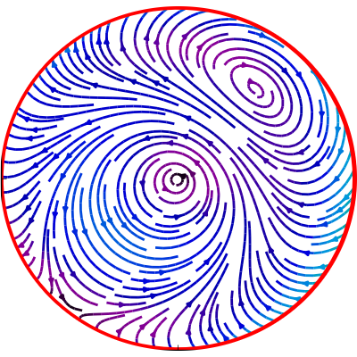
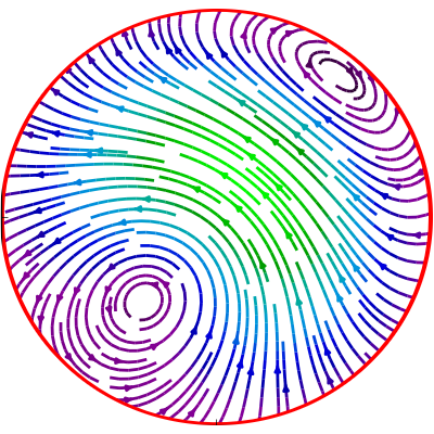
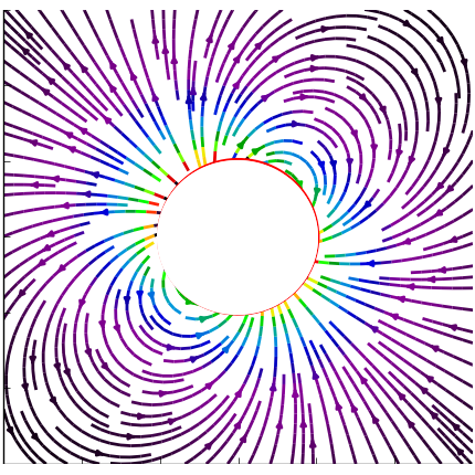
Figure 1: The panels show flow lines of the force density and flow fields in the xz plane with parameters α0=1,α1=α1=1.7+0.5i,γ0=1,γ1=γ1=1.2+1.7iformulae-sequenceformulae-sequencesubscript𝛼01subscript𝛼1superscriptsubscript𝛼11.70.5𝑖formulae-sequencesubscript𝛾01subscript𝛾1superscriptsubscript𝛾11.21.7𝑖\alpha_{0}=1,\alpha_{1}=-\alpha_{-1}^{*}=1.7+0.5\,i,\gamma_{0}=1,\gamma_{1}=-\gamma_{-1}^{*}=1.2+1.7\,i. Right panel: force density, middle panel: internal flow field, right panel: external flow field.

The total force and torque generated by this density vanishes. In Fig(1), the flow lines of the force density 𝐟𝐟\mathbf{f} and the flow fields 𝐯±superscript𝐯plus-or-minus\mathbf{v}^{\pm} are shown in the x-z plane

V Active stresses

To make contact with continuum descriptions of active matter inside a droplet or cell, let us consider an active stress tensor with cartesian components

σij(act)=(pi(𝐫)pj(𝐫)13p2(𝐫)δij).subscriptsuperscript𝜎𝑎𝑐𝑡𝑖𝑗subscript𝑝𝑖𝐫subscript𝑝𝑗𝐫13superscript𝑝2𝐫subscript𝛿𝑖𝑗\sigma^{(act)}_{ij}=\left(p_{i}(\mathbf{r})p_{j}(\mathbf{r})-\frac{1}{3}p^{2}(\mathbf{r})\delta_{ij}\right). (56)

This stress tensor orginates from an active polar medium described by the polarization field 𝐩(𝐫)𝐩𝐫\mathbf{p}(\mathbf{r}). Its origin is discussed in detail in Ref. K.Kruse et al. (2004); Joanny et al. (2007) Such active stresses generate a viscous flow inside the cell or droplet, which in turn gives rise to self-propulsion.

We restrict the discussion to the simple case of a director field, which only contains =00\ell=0 and =1,m=0formulae-sequence1𝑚0\ell=1,m=0 modes 111If we start from an expansion of a general 𝐩(𝐫)𝐩𝐫\mathbf{p}(\mathbf{r}) into vector spherical harmonics, the expansion of the terms quadratic in 𝐩𝐩\mathbf{p}, which determine 𝐟𝐟\mathbf{f}, can be performed straightforwardly by standard methods Edmonds (1957), but it is tedious and the result is not very illuminating. It has been worked out in detail in Moses (1974). , i.e. it can be written in the form

𝐩(r,θ,φ)=(p1(r)cosθ+p0(r))𝐞rp2(r)sinθ𝐞θ,𝐩𝑟𝜃𝜑subscript𝑝1𝑟𝜃subscript𝑝0𝑟subscript𝐞𝑟subscript𝑝2𝑟𝜃subscript𝐞𝜃\mathbf{p}(r,\theta,\varphi)=\big{(}p_{1}(r)\cos\theta+p_{0}(r)\big{)}\mathbf{e}_{r}-p_{2}(r)\sin\theta\mathbf{e}_{\theta}, (57)

To determine the interior flow, we first compute the body force density 𝐟=(𝐩)𝐩(𝐩)𝐩+(1/3)𝐩2𝐟𝐩𝐩𝐩𝐩13superscript𝐩2\mathbf{f}=-(\nabla\cdot\mathbf{p})\mathbf{p}-(\mathbf{p}\cdot\nabla)\mathbf{p}+(1/3)\nabla\mathbf{p}^{2} with the explicit result given in Appendix VIII.2. The polarization of Eq. 57 gives rise to force components with =0,1,2012\ell=0,1,2. The =00\ell=0-component can be absorbed into the inhomogeneous pressure (see Eq.(40)) and contributes to the balance of uniform outside and inside pressure by the uniform surface tension. We will comment on the =22\ell=2-component below and focus first on the =11\ell=1-component which determines the overall motion of the droplet:

fr(1)superscriptsubscript𝑓𝑟1\displaystyle f_{r}^{(1)} =\displaystyle= 43(p0p1)4rp0p1+2rp0p243superscriptsubscript𝑝0subscript𝑝14𝑟subscript𝑝0subscript𝑝12𝑟subscript𝑝0subscript𝑝2\displaystyle-\frac{4}{3}(p_{0}p_{1})^{\prime}-\frac{4}{r}p_{0}p_{1}+\frac{2}{r}p_{0}p_{2} (58)
fθ(1)superscriptsubscript𝑓𝜃1\displaystyle f_{\theta}^{(1)} =\displaystyle= (p0p2)+3rp0p223rp1p0superscriptsubscript𝑝0subscript𝑝23𝑟subscript𝑝0subscript𝑝223𝑟subscript𝑝1subscript𝑝0\displaystyle(p_{0}p_{2})^{\prime}+\frac{3}{r}p_{0}p_{2}-\frac{2}{3r}p_{1}p_{0}

where pi=dpi/drsuperscriptsubscript𝑝𝑖𝑑subscript𝑝𝑖𝑑𝑟p_{i}^{\prime}=dp_{i}/dr.

Without further assumptions on 𝐩(𝐫)𝐩𝐫\mathbf{p}(\mathbf{r}), we have both, active body forces and active tractions, so that the condition of vanishing total force reads

V𝑑V𝐟a(r)Vd2S𝝈act𝐧=0subscript𝑉differential-d𝑉superscript𝐟𝑎𝑟subscript𝑉superscript𝑑2𝑆superscript𝝈𝑎𝑐𝑡𝐧0\int_{V}dV\;{\bf f}^{a}(r)-\int_{\partial V}d^{2}S\;\boldsymbol{\sigma}^{act}{\bf n}=0 (59)

With the ansatz of Eq. 57, force balance can be checked explicitly by computing the two terms separately:

VdV𝐟a(r)=8π3a2p0(a)(2p1(a)/3+(p2(a))𝐞z=Vd2S𝝈act𝐧.\int_{V}dV\;{\bf f}^{a}(r)=-\frac{8\pi}{3}a^{2}p_{0}(a)(2p_{1}(a)/3+(p_{2}(a)){\bf e}_{z}=\int_{\partial V}d^{2}S\;\boldsymbol{\sigma}^{act}{\bf n}. (60)

A simple example for the polarization which vanishes on the surface of the droplet is: pi(r)=pir/a(1r/a)subscript𝑝𝑖𝑟subscript𝑝𝑖𝑟𝑎1𝑟𝑎p_{i}(r)=p_{i}r/a(1-r/a), implying the vanishing of the stress tensor on the surface of the droplet and hence the absence of tractions. The order parameter field and the corresponding force densities are shown for this example in Fig.(2).

Refer to caption
Refer to caption
Figure 2: Flow lines in the xz plane. Left: polar order parameter, eq.(57), Right: force density, eq.(86) with parameters p0=0.2,p1=p2=1formulae-sequencesubscript𝑝00.2subscript𝑝1subscript𝑝21p_{0}=0.2,p_{1}=p_{2}=1

The external flow field is easily computed from the general formalism in sec.IV.1. The details of the calculation are given in the Appendix VIII.2. The center of mass velocity of the droplet is determined by the viscosities of the inside and outside fluid, η±superscript𝜂plus-or-minus\eta^{\pm} and by the coeffcients of the polarization, p0,p1,p2subscript𝑝0subscript𝑝1subscript𝑝2p_{0},p_{1},p_{2}, according to:

𝐯CM=32πap03(2λ+3){7p1+p2210η2p1+11p260η+}𝐞zsubscript𝐯𝐶𝑀32𝜋𝑎subscript𝑝032𝜆37subscript𝑝1subscript𝑝2210superscript𝜂2subscript𝑝111subscript𝑝260superscript𝜂subscript𝐞𝑧{\bf v}_{CM}=\sqrt{\frac{3}{2\pi}}\frac{ap_{0}}{3(2\lambda+3)}\big{\{}\frac{7p_{1}+p_{2}}{210\eta^{-}}-\frac{2p_{1}+11p_{2}}{60\eta^{+}}\big{\}}\;{\mathbf{e}}_{z} (61)

If we think of a nematic liquid crystal, the director field has to fulfil boundary conditions on the surface of the droplet. We mention two possibilities: First, the director field is aligned with the surface, implying p0(a)=p1(a)=0subscript𝑝0𝑎subscript𝑝1𝑎0p_{0}(a)=p_{1}(a)=0. Second, the director field is oriented perpendicular to the surface, implying p2(a)=0subscript𝑝2𝑎0p_{2}(a)=0. In the first case, the tractions vanish, whereas in the second case, we have both active tractions and active body forces. The computations for the general case with both, nonzero body-forces and nonzero tractions is cumbersome but straightforward. Since we are dealing with linear equations the flow fields due to tractions as discussed in sec.III and the flow fields due to body-forces only as discussed in sec.IV can be superimposed.

Before closing this section, two remarks are in order. First, note that the =11\ell=1 components of the force density are all proportional to p0subscript𝑝0p_{0}, i.e. a director field, which only possesses =1,m=0formulae-sequence1𝑚0\ell=1,m=0 components, as for example 𝐩𝐞zproportional-to𝐩subscript𝐞𝑧\mathbf{p}\propto\mathbf{e}_{z}, will not lead to self-propulsion. Second and more important, note that our simple ansatz for the active stress in general gives rise to a force density with =22\ell=2. ( For the explicit expression, see Eq. 87 in Appendix VIII.2). Such a force density will in general cause deformations of the droplet away from its spherical shape. Physically these deformations are controlled by the surface tension, so that it should be possible to describe deformed droplets in a perturbation expansion in 1/γ01subscript𝛾01/\gamma_{0}.

VI Droplet trajectories

VI.1 Rigid active matter and droplet velocities

In the previous sections we have calculated the flow fields of a droplet in the laboratory frame at a single, fixed time. Now we we want to construct time dependent flows of the fluids and trajectories of the droplet as a continuum of such single time snapshots. This is possible if — in the limit of vanishing Reynolds number — the Strouhal number S=aΩ/U𝑆𝑎Ω𝑈S=a\Omega/U stays finite Kim and Karrila (2005). Here U𝑈U is a velocity scale of the internal flow 𝐯superscript𝐯\mathbf{v}^{-} , and S𝑆S compares a time-scale a/U𝑎𝑈a/U of flow to a time scale Ω1superscriptΩ1\Omega^{-1} of temporal changes of the active forces. But the time dependences of active force densities and tractions in the laboratory frame have not yet been specified. These densities are generated by active material, which shares the droplet’s interior with the Newtonian fluid, and which possesses its own evolution equations. The material in the interior of microorganisms has been modelled as mixtures of simple Dembo and Harlow (1986) and complex Kruse et al. (2005); Joanny et al. (2007) active and passive fluids, or as a biphasic poroelastic medium Biot (1955); Gennes (1976); Moeendarbary et al. (2013) with a distribution of active force densities or stress tensors, produced by molecular motors and (dis)-assembly of semi-flexible polymers Loisel et al. (1999). The resulting evolution equations are quite complex. In the present subsection we discuss the case of rigid active matter, immersed in a Newtonian fluid. This model, although highly simplified, is not unreasonable as an approximate continuum description on timescales, which do not exceed the reorganisation time of the cytosceleton. Its main advantage is that it allows for simple closed equations of motion of the droplet.

In every continuum description, we label an element of the active material by X𝑋X. At an initial time t=0𝑡0t=0 we assume that the element is at rest in LF at position 𝐗0subscript𝐗0\mathbf{X}_{0} in a quiet fluid, and in the course of time it follows a trajectory 𝐗(t)=𝐗(𝐗0,t)𝐗𝑡𝐗subscript𝐗0𝑡\mathbf{X}(t)=\mathbf{X}(\mathbf{X}_{0},t) with velocity 𝐯m(X,t)=d𝐗(t)/dtsubscript𝐯𝑚𝑋𝑡𝑑𝐗𝑡𝑑𝑡\mathbf{v}_{m}(X,t)=d\mathbf{X}(t)/dt. If, for example, the material elements do not interact and move convectively in the Newtonian fluid, the material velocity equals the fluid velocity 𝐯m(X,t)=𝐯(𝐗(t),t)subscript𝐯𝑚𝑋𝑡superscript𝐯𝐗𝑡𝑡\mathbf{v}_{m}(X,t)=\mathbf{v}^{-}(\mathbf{X}(t),t). Here we restrict the discussion to another simple case, inspired by self-propelling microorganisms. We suppose that the active material is tied to parts of a polymeric (cyto)-sceleton, which can be modelled as a rigid structure. Thus it can only undergo rigid body motions, composed of rotations 𝐑^(t)^𝐑𝑡\hat{\mathbf{R}}(t) with respect to some material point and translations 𝐛(t)𝐛𝑡\mathbf{b}(t), i.e. 𝐗(t)=𝐑^(t)𝐗(0)+𝐛(t)𝐗𝑡^𝐑𝑡𝐗0𝐛𝑡\mathbf{X}(t)=\hat{\mathbf{R}}(t)\mathbf{X}(0)+\mathbf{b}(t), and thus the corresponding material velocities are given by 𝐯m(𝐗,t)=𝐯0+𝝎(t)×[𝐗(t)𝐛(t)]subscript𝐯𝑚𝐗𝑡subscript𝐯0𝝎𝑡delimited-[]𝐗𝑡𝐛𝑡\mathbf{v}_{m}(\mathbf{X},t)=\mathbf{v}_{0}+\boldsymbol{\omega}(t)\times[\mathbf{X}(t)-\mathbf{b}(t)] with 𝐯0=d𝐛/dtsubscript𝐯0𝑑𝐛𝑑𝑡\mathbf{v}_{0}=d\mathbf{b}/dt.

As an additional constraint we require that the translational motion of the sceleton and the translational motion of the droplet coincide, i.e. 𝐯0=𝐯CMsubscript𝐯0subscript𝐯𝐶𝑀\mathbf{v}_{0}=\mathbf{v}_{CM}. The constraint can be realized in various ways, for example, by anchoring at least four material points of the sceleton (not all in the same plane) within the interface. This fixes the center of the sphere rigidly to the sceleton, reminiscent of the anchoring of the cytosceleton at the nucleus. The motion of the sceleton is thus restricted to rotations within the droplet. Without such a constraint, the sceleton could perform translational motions relative to the center of the sphere — as, for example, an active particle propelling in the interior of the droplet — which we do not want to discuss here.

Three frames of reference, which are used in the following, are defined with respect to the sceleton. At time t=0𝑡0t=0, when each X is placed at its corresponding 𝐗0subscript𝐗0\mathbf{X}_{0}, we choose a cartesian system, with its origin at the center of the sphere, 𝐫CMsubscript𝐫𝐶𝑀\mathbf{r}_{CM}, and unit vectors 𝐞α,α=1,2,3formulae-sequencesubscript𝐞𝛼𝛼123\mathbf{e}_{\alpha},\;\alpha=1,2,3. This is our laboratory frame LF. The frame at any other time, with its origin at 𝐗(𝐗0=𝟎,t)𝐗subscript𝐗00𝑡\mathbf{X}(\mathbf{X}_{0}=\mathbf{0},t) and rotated unit vectors 𝐑^(t)𝐞α^𝐑𝑡subscript𝐞𝛼\hat{\mathbf{R}}(t)\mathbf{e}_{\alpha} is called the comoving frame CMF. At t=0𝑡0t=0, CMF and LF coincide, i.e. 𝐑^(0)=𝟏^^𝐑0^1\hat{\mathbf{R}}(0)=\hat{\mathbf{1}} and 𝐝(0)=𝟎𝐝00\mathbf{d}(0)=\mathbf{0}. Per definition, the sceleton is at rest in the CMF. Its structure is described by a continuous density ρp(X)subscript𝜌𝑝𝑋\rho_{p}(X), carrying a force density 𝐟(X,t)𝐟𝑋𝑡\mathbf{f}(X,t), which may depend upon time. Another laboratory frame, with origin and axes coinciding with those of the CMF at a fixed instant t𝑡t will be called a momentary material frame MMF in the following. The calculations of Sec (III)- (V) have been performed in this frame.

The active matter in the droplet’s interior will in general also modify the internal flow field. For a droplet filled with a rigid gel and a viscous fluid, there is an additional permeation force Callan and Jülicher (2011), which enters the force balance. This leads to a modified Stokes equation of the form 𝝈=pΓ(ρp)(𝐯𝐯m)𝐟act𝐟extsuperscript𝝈𝑝Γsubscript𝜌𝑝𝐯superscript𝐯𝑚superscript𝐟𝑎𝑐𝑡superscript𝐟𝑒𝑥𝑡\nabla\cdot\boldsymbol{\sigma}^{-}=\nabla p-\Gamma(\rho_{p})(\mathbf{v}-\mathbf{v}^{m})-\mathbf{f}^{act}-\mathbf{f}^{ext}. Here Γ(ρp)Γsubscript𝜌𝑝\Gamma(\rho_{p}) is is a permeation coefficient, which depends upon the detailed structure of the gel. In the following, we will assume that the gel fraction is small and Γ(ρp)λρp1Γsubscript𝜌𝑝𝜆subscript𝜌𝑝much-less-than1\Gamma(\rho_{p})\approx\lambda\rho_{p}\ll 1, which allows to neglect the permeation force. Then 𝐯superscript𝐯\mathbf{v}^{-} is entirely due to the active and external force densities, and can be calculated using Eq. (1).

The time-dependence of the force density 𝐟(𝐫,t)𝐟𝐫𝑡\mathbf{f}(\mathbf{r},t) and the sceleton density ρp(𝐫,t)subscript𝜌𝑝𝐫𝑡\rho_{p}(\mathbf{r},t) produced by active material at position 𝐫𝐫\mathbf{r} are now easily obtained. In the CMF, the position and orientation of each material element is time independent and only the explicit time dependence of the force density reamains, i.e. ρp(𝐫,t)=ρp(𝐗0=𝐫)subscript𝜌𝑝𝐫𝑡subscript𝜌𝑝subscript𝐗0𝐫\rho_{p}(\mathbf{r},t)=\rho_{p}(\mathbf{X}_{0}=\mathbf{r}) and 𝐟(𝐫,t)=𝐟(𝐗0=𝐫,t)𝐟𝐫𝑡𝐟subscript𝐗0𝐫𝑡\mathbf{f}(\mathbf{r},t)=\mathbf{f}(\mathbf{X}_{0}=\mathbf{r},t). In the LF these quantities are co-translated and co-rotated along the trajectory of the active material element, so that

dfi(𝐫,t)dt=(𝐯CM+𝝎×𝐫)𝐟i(𝐫,t)+fit,𝑑subscript𝑓𝑖𝐫𝑡𝑑𝑡subscript𝐯𝐶𝑀𝝎𝐫subscript𝐟𝑖𝐫𝑡subscript𝑓𝑖𝑡\frac{df_{i}(\mathbf{r},t)}{dt}=\Big{(}\mathbf{v}_{CM}+\boldsymbol{\omega}\times\mathbf{r}\Big{)}\cdot\nabla\mathbf{f}_{i}(\mathbf{r},t)+\frac{\partial f_{i}}{\partial t}, (62)

and correspondingly dρp(𝐫,t)/dt=(𝐯CM+𝝎×𝐫)ρp(t).𝑑subscript𝜌𝑝𝐫𝑡𝑑𝑡subscript𝐯𝐶𝑀𝝎𝐫subscript𝜌𝑝𝑡d\rho_{p}(\mathbf{r},t)/dt=\Big{(}\mathbf{v}_{CM}+\boldsymbol{\omega}\times\mathbf{r}\Big{)}\cdot\nabla\rho_{p}(t). Thus in the MMF the time dependences of ρpsubscript𝜌𝑝\rho_{p} and 𝐟𝐟\mathbf{f} are the same as in the CMF for rigid active matter, which is the main reason for us to use this frame in our calculations.

In the following, we will refer to 𝝎𝝎\boldsymbol{\omega} of the sceleton as the angular velocity of the droplet. If the whole droplet is rotating like a rigid body, this definition coincides with that of a self-propelling particle. But note that there is no unambiguous definition of angular velocity of a droplet, if the internal flow field 𝐯superscript𝐯\mathbf{v}^{-} does not correspond to rigid body rotations.

To compute the angular velocity of the sceleton from the flow field 𝐯superscript𝐯\mathbf{v}^{-}, we consider the dissipative forces exerted by the flow on the sceleton in the MMF as proportional to the relative velocity between sceleton and fluid, i.e. proportional to Kρp(𝐯m𝐯)𝑑Vsubscript𝐾subscript𝜌𝑝subscript𝐯𝑚superscript𝐯differential-d𝑉\int_{K}\rho_{p}(\mathbf{v}_{m}-\mathbf{v}^{-})\,dV. A part of these forces is compensated by the rigid constraints, the other part is the only remaining force on the sceleton, which thus has to vanish. A convenient way to calculate the uncompensated generalized force on the rigid sceleton is to start from the dissipation function Landau and Lifshitz (1976) D(𝝎)=(ζ/2)Kρp(𝐫)(𝐯m(𝐫)𝐯(𝐫))2𝑑V𝐷𝝎𝜁2subscript𝐾subscript𝜌𝑝𝐫superscriptsuperscript𝐯𝑚𝐫superscript𝐯𝐫2differential-d𝑉D(\boldsymbol{\omega})=(\zeta/2)\int_{K}\rho_{p}(\mathbf{r})(\mathbf{v}^{m}(\mathbf{r})-\mathbf{v}^{-}(\mathbf{r}))^{2}dV. The friction coefficient ζ𝜁\zeta is unimportant in the following. The derivative of D𝐷D with respect to 𝝎𝝎\boldsymbol{\omega} is the generalized force, which has to vanish. The resulting relation K[𝐫×(𝐯CM+𝝎m×𝐫𝐯)]ρp𝑑V=0subscript𝐾delimited-[]𝐫subscript𝐯𝐶𝑀superscript𝝎𝑚𝐫superscript𝐯subscript𝜌𝑝differential-d𝑉0\int_{K}[\mathbf{r}\times(\mathbf{v}_{CM}+\boldsymbol{\omega}^{m}\times\mathbf{r}-\mathbf{v}^{-})]\rho_{p}dV=0 can be written in the form

j=13𝐈ij(t)ωj(t)=K[ρp(𝐫,t)𝐫×(𝐯(𝐫,t)𝐯CM(t))]i𝑑Vsuperscriptsubscript𝑗13subscript𝐈𝑖𝑗𝑡subscript𝜔𝑗𝑡subscript𝐾subscriptdelimited-[]subscript𝜌𝑝𝐫𝑡𝐫superscript𝐯𝐫𝑡subscript𝐯𝐶𝑀𝑡𝑖differential-d𝑉\sum_{j=1}^{3}\mathbf{I}_{ij}(t)\omega_{j}(t)=\int_{K}\big{[}\rho_{p}(\mathbf{r},t)\mathbf{r}\times(\mathbf{v}^{-}(\mathbf{r},t)-\mathbf{v}_{CM}(t))\big{]}_{i}\,dV (63)

Here 𝐈ij=ρp(r2δijxixj)subscript𝐈𝑖𝑗subscript𝜌𝑝superscript𝑟2subscript𝛿𝑖𝑗subscript𝑥𝑖subscript𝑥𝑗\mathbf{I}_{ij}=\int\rho_{p}(r^{2}\delta_{ij}-x_{i}x_{j}). Note that 𝝎𝝎\boldsymbol{\omega} depends on the structure of the sceleton. If it is spherically symmetric 𝐈ij=Iδijsubscript𝐈𝑖𝑗𝐼subscript𝛿𝑖𝑗\mathbf{I}_{ij}=I\delta_{ij} with I=(8π/3)0aρp(r)r4𝐼8𝜋3superscriptsubscript0𝑎subscript𝜌𝑝𝑟superscript𝑟4I=(8\pi/3)\int_{0}^{a}\rho_{p}(r)r^{4} and we get

𝝎=1IKρp(r)𝐫×𝐯𝑑V𝝎1𝐼subscript𝐾subscript𝜌𝑝𝑟𝐫superscript𝐯differential-d𝑉\boldsymbol{\omega}=\frac{1}{I}\int_{K}\rho_{p}(r)\mathbf{r}\times\mathbf{v}^{-}\,dV (64)

For a homogeneous ρp(r)=ρpsubscript𝜌𝑝𝑟subscript𝜌𝑝\rho_{p}(r)=\rho_{p} the constant I𝐼I becomes I=(8πa5/15)ρp𝐼8𝜋superscript𝑎515subscript𝜌𝑝I=(8\pi a^{5}/15)\rho_{p}, whereas for a thin shell ρp(r)=ρpδ(ra)subscript𝜌𝑝𝑟subscript𝜌𝑝𝛿𝑟𝑎\rho_{p}(r)=\rho_{p}\delta(r-a) it is I=(8πa4/3)ρp𝐼8𝜋superscript𝑎43subscript𝜌𝑝I=(8\pi a^{4}/3)\rho_{p}. Note that for inhomogeneous ρp(r)subscript𝜌𝑝𝑟\rho_{p}(r), there is a relative rotational motion between the internal fluid and the sceleton like that observed, for example, in rotations of a cell nucleusKumar et al. (2014).

VI.2 Trajectories

To determine trajectories of the droplet in LF, we can use Eq. (6) and Eqs. (63, 64). Due to our assumption that the active material is tied to a sparse rigid gel, the dynamics of the sceleton in LF is fully characterized by the transformation of the MMF, spanned by coordinate unit vectors 𝐞i,i=1,2,3formulae-sequencesubscript𝐞𝑖𝑖123\mathbf{e}_{i},\;i=1,2,3 rooted at the center of the sphere, 𝐫CM(t)subscript𝐫𝐶𝑀𝑡\mathbf{r}_{CM}(t), into the cartesian LF spanned by 𝐚i,i=1,2,3formulae-sequencesubscript𝐚𝑖𝑖123\mathbf{a}_{i},\;i=1,2,3. The equations of motion for the droplet thus become

d𝐫CMdt=i=13vCM,i(t)𝐞i(t)𝑑subscript𝐫𝐶𝑀𝑑𝑡superscriptsubscript𝑖13subscript𝑣𝐶𝑀𝑖𝑡subscript𝐞𝑖𝑡\frac{d\mathbf{r}_{CM}}{dt}=\sum_{i=1}^{3}v_{CM,i}(t)\mathbf{e}_{i}(t) (65)
d𝐞idt=𝝎(𝒕)×𝐞i(t).𝑑subscript𝐞𝑖𝑑𝑡𝝎𝒕subscript𝐞𝑖𝑡\frac{d\mathbf{e}_{i}}{dt}=\boldsymbol{\omega(t)}\times\mathbf{e}_{i}(t). (66)

Here, we insert 𝐯CMsubscript𝐯𝐶𝑀\mathbf{v}_{CM} and 𝝎𝝎\boldsymbol{\omega} as calculated from the internal flow.

In the following we want to present a few simple, illustrating examples, showing trajectories of the center of mass and the rotational motion of a vector 𝐛(t)=ibi𝐞i(t)𝐫CM(t)𝐛𝑡subscript𝑖subscript𝑏𝑖subscript𝐞𝑖𝑡subscript𝐫𝐶𝑀𝑡\mathbf{b}(t)=\sum_{i}b_{i}\mathbf{e}_{i}(t)-\mathbf{r}_{CM}(t). In the figures depicted below we choose bi=1,i=1,2,3formulae-sequencesubscript𝑏𝑖1𝑖123b_{i}=1,i=1,2,3.

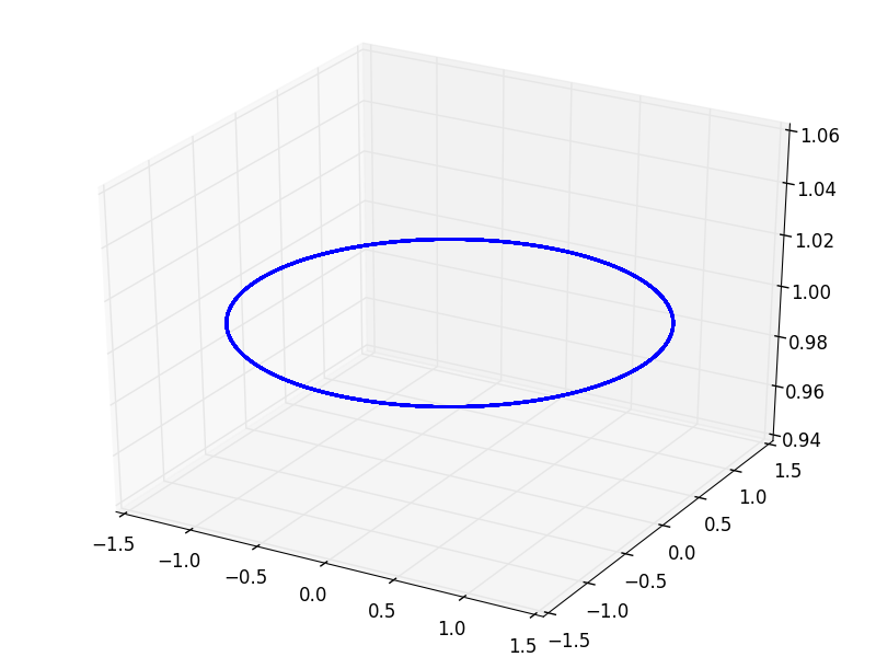
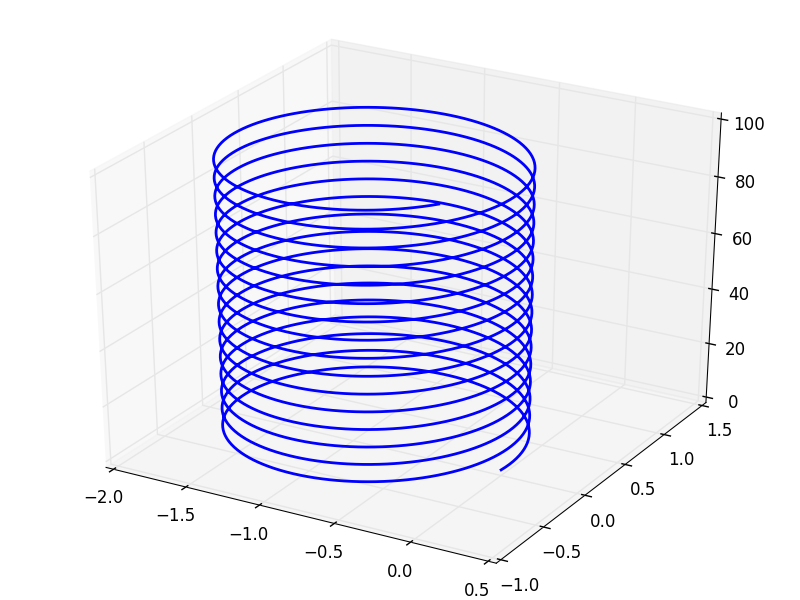
For time-independent force densities, the trajectories from Eqs. (65, 66) are helices as shown in Fig (3). The axis of the helix is parallel to 𝝎𝝎\boldsymbol{\omega}, which we have chosen to to be the z-axis.
Refer to caption
Refer to caption
Figure 3: For time indendent force densities and/or tractions, the trajectories are straight lines (for 𝝎=0𝝎0\boldsymbol{\omega}=0) or helices (for 𝝎0𝝎0\boldsymbol{\omega}\neq 0). The example shows a trajectory with 𝝎=𝐞z𝝎subscript𝐞𝑧\boldsymbol{\omega}=\mathbf{e}_{z} and 𝐯CM=0.3𝐞x+0.2𝐞y+𝐞zsubscript𝐯𝐶𝑀0.3subscript𝐞𝑥0.2subscript𝐞𝑦subscript𝐞𝑧\mathbf{v}_{CM}=0.3\mathbf{e}_{x}+0.2\mathbf{e}_{y}+\mathbf{e}_{z}. Left panel depicts 𝐫CM(t)subscript𝐫𝐶𝑀𝑡\mathbf{r}_{CM}(t), right panel illustrates the rotational motion via 𝐛(t)𝐛𝑡\mathbf{b}(t), defined in the main text.

Fig (4) shows an interesting case of translational motion. It results from force densities — and thus from vCMsubscript𝑣𝐶𝑀v_{CM} and 𝝎𝝎\boldsymbol{\omega} — which vanish when averaged over one period. In the shown example, the angular velocity 𝝎=0.1sin(t)𝐞3𝝎0.1𝑡subscript𝐞3\boldsymbol{\omega}=0.1\sin(t)\mathbf{e}_{3} and the translational velocity 𝐯CM=0.1sin(t)𝐞1+0.1cos(t)𝐞2subscript𝐯𝐶𝑀0.1𝑡subscript𝐞10.1𝑡subscript𝐞2\mathbf{v}_{CM}=0.1\sin(t)\mathbf{e}_{1}+0.1\cos(t)\mathbf{e}_{2} are simple harmonic functions, and for simplicty are chosen such that the trajectories stay in the x-y plane. The rotational motion is easily integrated analytically and leads to 𝐞1=cosΦ(t)𝐚1sinΦ(t)𝐚2subscript𝐞1Φ𝑡subscript𝐚1Φ𝑡subscript𝐚2\mathbf{e}_{1}=\cos\Phi(t)\mathbf{a}_{1}-\sin\Phi(t)\mathbf{a}_{2} and 𝐞2=sinΦ(t)𝐚1+cosΦ(t)𝐚2subscript𝐞2Φ𝑡subscript𝐚1Φ𝑡subscript𝐚2\mathbf{e}_{2}=\sin\Phi(t)\mathbf{a}_{1}+\cos\Phi(t)\mathbf{a}_{2} with Φ(t)=1costΦ𝑡1𝑡\Phi(t)=1-\cos t, depicted in Fig.(4 b).

Refer to caption
Refer to caption
Figure 4: Periodic force densities and/or tractions with vanishing averages over one period may nevertheless lead to unbounded translations. The left panel shows the trajectory of 𝐫CMsubscript𝐫𝐶𝑀\mathbf{r}_{CM}, the right panel depicts the rotational motion of 𝐛(t)𝐛𝑡\mathbf{b}(t) (see main text) for 𝝎=0.1sin(t)𝐞z𝝎0.1𝑡subscript𝐞𝑧\boldsymbol{\omega}=0.1\sin(t)\mathbf{e}_{z} and 𝐯CM=0.1sin(t)𝐞x+0.1cos(t)𝐞ysubscript𝐯𝐶𝑀0.1𝑡subscript𝐞𝑥0.1𝑡subscript𝐞𝑦\mathbf{v}_{CM}=0.1\sin(t)\,\mathbf{e}_{x}+0.1\cos(t)\,\mathbf{e}_{y}

.

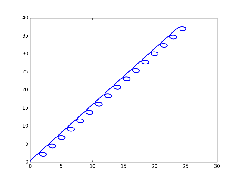
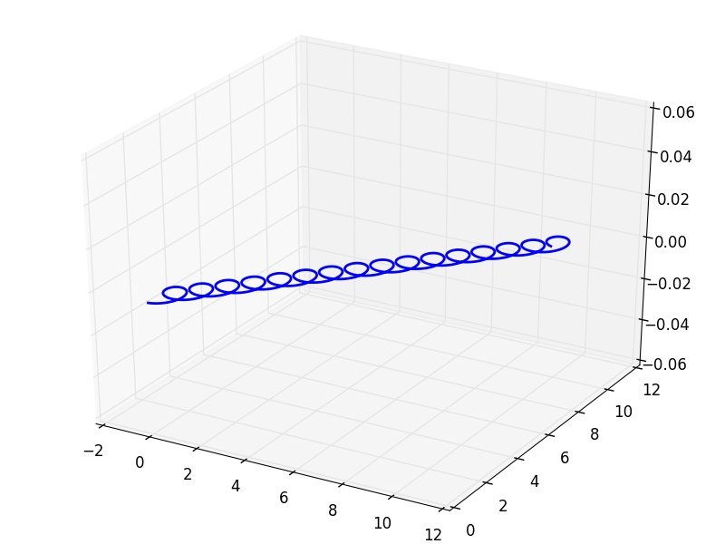
To illustrate the increasing complexity of trajectories, which can be generated, we next add simple cases due to forces with a single frequency ΩΩ\Omega . In Fig(5 a), the angular velocity vanishes, nevertheless the trajectory is a spiral. This type of motion arises from periodic velocities 𝐯CM(t)=i(vi+uisin(Ωt))𝐞isubscript𝐯𝐶𝑀𝑡subscript𝑖subscript𝑣𝑖subscript𝑢𝑖Ω𝑡subscript𝐞𝑖\mathbf{v}_{CM}(t)=\sum_{i}(v_{i}+u_{i}\sin(\Omega t))\mathbf{e}_{i}, characterized by a non-vanishing average 𝐯=(v1,v2,v3)𝐯subscript𝑣1subscript𝑣2subscript𝑣3\mathbf{v}=(v_{1},v_{2},v_{3}) over one period and additional periodic terms of 𝐯CMsubscript𝐯𝐶𝑀\mathbf{v}_{CM}, which may have different amplitudes uisubscript𝑢𝑖u_{i} ΩΩ\Omega for each cartesian component.

Refer to caption
Refer to caption
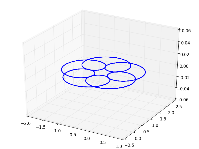
Figure 5: Left panel: Helical motion arising from periodic, non-chiral force densities, which lead to 𝐯CM=(0.1+0.6cost)𝐞x+(0.1+0.6sint)𝐞ysubscript𝐯𝐶𝑀0.10.6𝑡subscript𝐞𝑥0.10.6𝑡subscript𝐞𝑦\mathbf{v}_{CM}=(0.1+0.6\cos t)\,\mathbf{e}_{x}+(0.1+0.6\sin t)\,\mathbf{e}_{y} and 𝝎=0𝝎0\boldsymbol{\omega}=0. Right panel: A chiral force density, leading to a rotation with 𝝎=0.2𝐞z𝝎0.2subscript𝐞𝑧\boldsymbol{\omega}=0.2\mathbf{e}_{z} is added to the system of the left panel, resulting in rosette-shaped trajectories. The depicted rosette is simple and closed, because the the ratio of the frequencies of 𝐯CMsubscript𝐯𝐶𝑀\mathbf{v}_{CM} (which is 1) and 𝝎𝝎\boldsymbol{\omega} of this example is a rational number (1/5).

More complex, rosette shaped trajectories — possibly superimposed with a translation— appear, if a constant angular velocity is added to periodic translation velocities, as shown in Fig.(5 b).

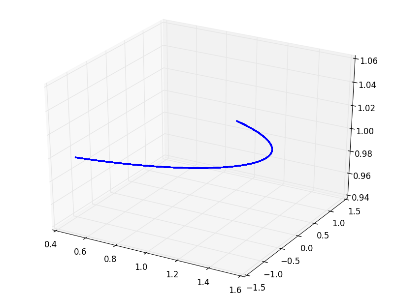
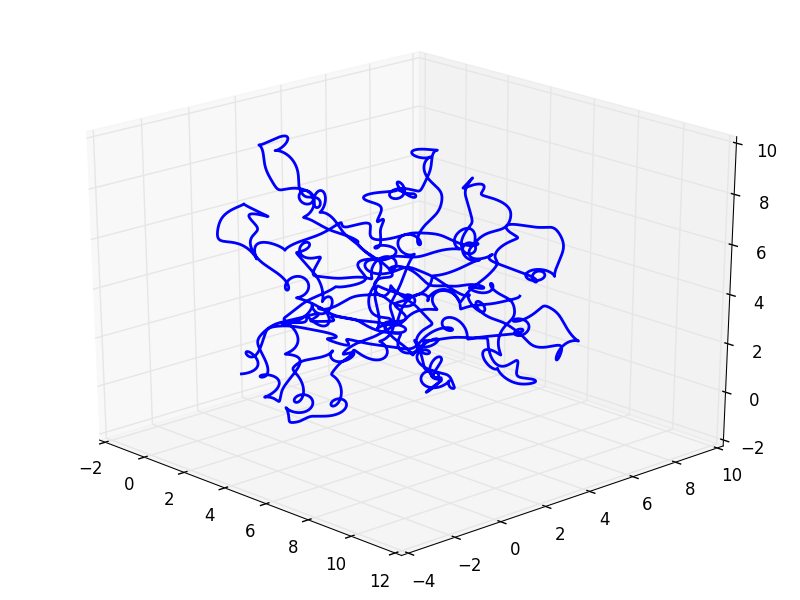
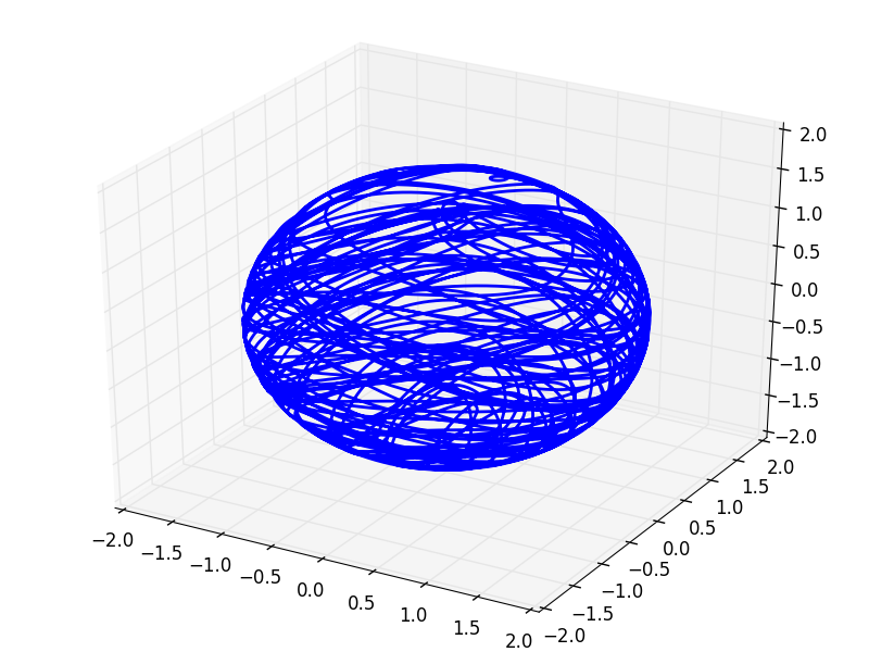
Finally, if forces contain more than one frequency, the zoology of trajectories gets more and more involved and will be discussed elsewhere. As an example, Fig. (6) shows the translational and rotational motion of a complex 3-dimensional trajectory with complex rotation.
Refer to caption
Refer to caption
Figure 6: This example shows a complex trajectory of 𝐫CMsubscript𝐫𝐶𝑀\mathbf{r}_{CM} and of 𝐛𝐛\mathbf{b} (see main text), resulting from an angular velocity vector 𝝎=0.5sint𝐞x+0.3sin(2t)𝐞y+𝐞z𝝎0.5𝑡subscript𝐞𝑥0.32𝑡subscript𝐞𝑦subscript𝐞𝑧\boldsymbol{\omega}=0.5\sin t\mathbf{e}_{x}+0.3\sin(\sqrt{2}t)\mathbf{e}_{y}+\mathbf{e}_{z} and a translational velocity 𝐯CM=0.6sin(1.9t)𝐞x+0.8sin(1.1t)𝐞y+0.4sin(0.3t)𝐞zsubscript𝐯𝐶𝑀0.61.9𝑡subscript𝐞𝑥0.81.1𝑡subscript𝐞𝑦0.40.3𝑡subscript𝐞𝑧\mathbf{v}_{CM}=0.6\sin(1.9t)\,\mathbf{e}_{x}+0.8\sin(1.1t)\,\mathbf{e}_{y}+0.4\sin(0.3t)\,\mathbf{e}_{z}. It is generated by force densities with 5 different non-vanishing frequencies and a constant component.

VII Conclusions and Outlook

We have shown that spherical droplets of immiscible fluids can be propelled by several activity mechanisms beyond the model of a squirmer. An important case are active stresses inside the droplet. An example is an active polar medium, whose polarization 𝐩𝐩{\bf p} generates active stresses of the form σijactpipjp2δij/3similar-tosuperscriptsubscript𝜎𝑖𝑗𝑎𝑐𝑡subscript𝑝𝑖subscript𝑝𝑗superscript𝑝2subscript𝛿𝑖𝑗3\sigma_{ij}^{act}\sim p_{i}p_{j}-p^{2}\delta_{ij}/3. Alternatively, the activity is generated by body forces in the interior of the droplet, an example are motors pulling filaments and thereby giving rise to a force-dipole density. Another class of active mechanisms are localised in the interface of the droplet, giving rise to surface tractions, tjact=niσijactsuperscriptsubscript𝑡𝑗𝑎𝑐𝑡subscript𝑛𝑖superscriptsubscript𝜎𝑖𝑗𝑎𝑐𝑡t_{j}^{act}=n_{i}\sigma_{ij}^{act}. These can for example be generated by active elements in a thin, approximately 2-dimensional polymer network at the interface. Active stresses inside the droplet, which are discontinuous across the interface, also give rise to tractions localised at the interface, so that the general case comprises both, tractions and body forces.

Our approach is based on a 2-step procedure. We first compute the instantaneous internal and external flow fields as well as the linear and angular momentum of the droplet. The flow fields and the momenta of the droplet are shown to depend on properties of both fluids, i.e. the viscosities of the interior and exterior fluid. Energy is dissipated also in the interior of the droplet with the ratio of dissipated energies in the outside and inside being universal, indepedent of the driving activity.

To compute time dependent flow fields and trajectories of the droplet, we need to specify the dynamics of the activity mechanism in a second step. We model these as being tied to a rigid sceleton, which is constrained to translate with the droplet.

In the absence of an explicit time dependence of activity, the droplet trajectories are spirals with in general noncollinear translational and rotational velocities. Specifically for surface tractions, as generated e.g. by an inhomogenous surface tension, the angular velocity vanishes for the autonomous swimmer, i.e. in the absence of torques.

More generally, we allow for an explicit time-dependence of the activity mechanism, such as active forces oscillating with frequency ΩΩ\Omega. In order to construct a droplet trajectory as a sequence of snapshots, which have been computed in the first step of our procedure, the inertial terms in the Navier Stokes equation have to remain negligible. This is the guaranteed, if the Reynold‘s number is small and the Strouhal number, S=aΩ/U𝑆𝑎Ω𝑈S=a\Omega/U, remains finite. Here a/U𝑎𝑈a/U is a charcateristic timescale of the internal flow. We show that oscillating active forces can give rise to very complex trajectories, but postpone a systematic study to future work.

Our approach can be extended in several ways. One problem of interest is the motion of an active droplet in nonzero ambient flow, e.g. a droplet in channel flow or shear flow. This might involve shape changes of the droplet which have not been considered so far, because we have mainly restricted ourselves to l=1𝑙1l=1. However a perturbative analysis of shape changes along the lines of should be possible Taylor (1934); Vlahoska et al. (2009). The proposed formalism is general enough to discuss the force free case as well as droplet motion in the presence of external forces. So far we have analysed the simplest case only, a sedimenting active droplet, but it is straightforward to extend the analysis to more complex potentials, such as an optical trap. Another interesting extension refers to the interaction of active droplets - possibly giving rise to collective behaviour.

Finally, the modelling of the droplet can and should be improved in various ways. One possibility is a two fluid model for the interior, another line of approach should account explicitly for the gel fraction and the permeation force. Furthermore it is highly desirable to study vesicles, enclosed by a membrane, or even cells enclosed by an elastic cortex. Work along these lines is in progress.

VIII Appendix

VIII.1 General solution of homogeneous Stokes equations in vector spherical harmonics

To solve boundary value problems of the Stokes equations,

η2𝐯=p,𝐯=0,formulae-sequence𝜂superscript2𝐯𝑝𝐯0\eta\nabla^{2}\mathbf{v}=\nabla p,\quad\nabla\cdot\mathbf{v}=0, (67)

with a spherical interface Γ(a)Γ𝑎\Gamma(a) at r=a𝑟𝑎r=a, we use expansions in terms of scalar and vector spherical harmonics (VSH). Whereas scalar spherical harmonics Ymsubscript𝑌𝑚Y_{\ell m} are fairly standardized, there exist several versions of vector spherical harmonics. Here we use

𝐘m0subscript𝐘𝑚0\displaystyle\mathbf{Y}_{\ell m0} =\displaystyle= Ym𝐞rsubscript𝑌𝑚subscript𝐞𝑟\displaystyle Y_{\ell m}\mathbf{e}_{r} (68)
𝐘m1subscript𝐘𝑚1\displaystyle\mathbf{Y}_{\ell m1} =\displaystyle= s𝐘msubscript𝑠subscript𝐘𝑚\displaystyle\nabla_{s}\mathbf{Y}_{\ell m} (69)
𝐘m2subscript𝐘𝑚2\displaystyle\mathbf{Y}_{\ell m2} =\displaystyle= 𝐞r×s𝐘msubscript𝐞𝑟subscript𝑠subscript𝐘𝑚\displaystyle\mathbf{e}_{r}\times\nabla_{s}\mathbf{Y}_{\ell m} (70)

These functions form a complete orthogonal set on the surface of a sphere with respect to the scalar product (𝐟,𝐠)=11d(cosθ)02π𝑑φ𝐟(θ,φ)𝐠(θ,φ)𝐟𝐠superscriptsubscript11𝑑𝜃superscriptsubscript02𝜋differential-d𝜑superscript𝐟𝜃𝜑𝐠𝜃𝜑(\mathbf{f},\mathbf{g})=\int_{-1}^{1}d(\cos\theta)\int_{0}^{2\pi}d\varphi\,\mathbf{f}^{*}(\theta,\varphi)\cdot\mathbf{g}(\theta,\varphi). The s=0𝑠0s=0 functions are normalized to 111, whereas the s=1,2𝑠12s=1,2 functions have norm (+1)1\sqrt{\ell(\ell+1)}.

Formulas for the elementary vector analytic operations gradient, divergence and curl acting on the 𝐘mssubscript𝐘𝑚𝑠\mathbf{Y}_{\ell ms} can be found, for example in Morse and Feshbach (1953). For the reader’s convenience, we include the representation of a gradient and a divergence, which will be used below. For p𝑝\nabla p one gets

p(r,θ,φ)=ms(p)ms𝐘ms=,mdpmdr𝐘m0+pmr𝐘m1,𝑝𝑟𝜃𝜑subscript𝑚𝑠subscript𝑝𝑚𝑠subscript𝐘𝑚𝑠subscript𝑚𝑑subscript𝑝𝑚𝑑𝑟subscript𝐘𝑚0subscript𝑝𝑚𝑟subscript𝐘𝑚1\nabla p(r,\theta,\varphi)=\sum_{\ell ms}(\nabla p)_{\ell ms}\mathbf{Y}_{\ell ms}=\sum_{\ell,m}\frac{dp_{\ell m}}{dr}\,\mathbf{Y}_{\ell m0}+\frac{p_{\ell m}}{r}\,\mathbf{Y}_{\ell m1}, (71)

where msubscript𝑚\sum_{\ell m} runs over =0,1,2,012\ell=0,1,2,\cdots and m𝑚m runs from -\ell to \ell. The divergence takes on the form

𝐯=m(𝐯)mYm=ms(dvm0dr+2rvm0(+1)rvm1)Ym𝐯subscript𝑚subscript𝐯𝑚subscript𝑌𝑚subscript𝑚𝑠𝑑subscript𝑣𝑚0𝑑𝑟2𝑟subscript𝑣𝑚01𝑟subscript𝑣𝑚1subscript𝑌𝑚\nabla\cdot\mathbf{v}=\sum_{\ell m}(\nabla\cdot\mathbf{v})_{\ell m}Y_{\ell m}=\sum_{\ell ms}\left(\frac{dv_{\ell m0}}{dr}+\frac{2}{r}v_{\ell m0}-\frac{\ell(\ell+1)}{r}v_{\ell m1}\right)Y_{\ell m} (72)

The incompressibility constraint implies two relations: First, p𝑝p obeys the Laplace equation 2p(r,θ,φ)=0superscript2𝑝𝑟𝜃𝜑0\nabla^{2}p(r,\theta,\varphi)=0, which is equivalent to

d2pm(r)dr2+2rdpmdr(+1)rpm=0superscript𝑑2subscript𝑝𝑚𝑟𝑑superscript𝑟22𝑟𝑑subscript𝑝𝑚𝑑𝑟1𝑟subscript𝑝𝑚0\frac{d^{2}p_{\ell m}(r)}{dr^{2}}+\frac{2}{r}\frac{dp_{\ell m}}{dr}-\frac{\ell(\ell+1)}{r}p_{\ell m}=0 (73)

for all possible \ell and m𝑚m, and second the expansion coefficients vm0subscript𝑣𝑚0v_{\ell m0} and vm1subscript𝑣𝑚1v_{\ell m1} are related by

dvm0dr+2rvm0=(+1)rvm1𝑑subscript𝑣𝑚0𝑑𝑟2𝑟subscript𝑣𝑚01𝑟subscript𝑣𝑚1\frac{dv_{\ell m0}}{dr}+\frac{2}{r}v_{\ell m0}=\frac{\ell(\ell+1)}{r}v_{\ell m1} (74)

The vector Laplace operator 2𝐯superscript2𝐯\nabla^{2}\mathbf{v} is diagonal in \ell and m𝑚m, but for the VSH defined in Eq. (68) it is not diagonal in the index s𝑠s. It is easily chcked by direct calculation that 2𝐘ms=shsst𝐘𝐦𝐬/r2superscript2subscript𝐘𝑚𝑠subscriptsuperscript𝑠subscriptsuperscript𝑡superscript𝑠𝑠subscript𝐘superscript𝐦𝐬superscript𝑟2\nabla^{2}\mathbf{Y}_{\ell ms}=\sum_{s^{\prime}}h^{t}_{s^{\prime}s}\mathbf{Y_{\ell ms^{\prime}}}/r^{2}. The coefficients hsst=hsssubscriptsuperscript𝑡𝑠superscript𝑠subscriptsuperscript𝑠𝑠h^{t}_{ss^{\prime}}=h_{s^{\prime}s} define a 3×3333\times 3 matrix h^^\hat{h}, which is given by

h^=([2+(+1)]2(+1)02(+1)000(+1)),^matrixdelimited-[]21210210001\hat{h}=\begin{pmatrix}-[2+\ell(\ell+1)]&2\ell(\ell+1)&0\\ 2&-\ell(\ell+1)&0\\ 0&0&-\ell(\ell+1)\end{pmatrix}, (75)

and which may be used to write the vector Laplace operator in the form

2𝐯=lms(2𝐯)ms𝐘mssuperscript2𝐯subscript𝑙𝑚𝑠subscriptsuperscript2𝐯𝑚𝑠subscript𝐘𝑚𝑠\nabla^{2}\mathbf{v}=\sum_{lms}(\nabla^{2}\mathbf{v})_{\ell ms}\mathbf{Y}_{\ell ms} (76)

with

(2𝐯)ms=s{(d2dr2+2rddr)δss+hss}vms(r)subscriptsuperscript2𝐯𝑚𝑠subscriptsuperscript𝑠superscript𝑑2𝑑superscript𝑟22𝑟𝑑𝑑𝑟subscript𝛿𝑠superscript𝑠subscript𝑠superscript𝑠subscript𝑣𝑚superscript𝑠𝑟(\nabla^{2}\mathbf{v})_{\ell ms}=\sum_{s^{\prime}}\left\{\left(\frac{d^{2}}{dr^{2}}+\frac{2}{r}\frac{d}{dr}\right)\delta_{ss^{\prime}}+h_{ss^{\prime}}\right\}v_{\ell ms^{\prime}}(r) (77)

The Stokes equations now take on the form of decoupled mode equations,

η(2𝐯)ms=(p)ms,(𝐯)lm=0.formulae-sequence𝜂subscriptsuperscript2𝐯𝑚𝑠subscript𝑝𝑚𝑠subscript𝐯𝑙𝑚0\eta(\nabla^{2}\mathbf{v})_{\ell ms}=(\nabla p)_{\ell ms},\quad(\nabla\cdot\mathbf{v})_{lm}=0. (78)

Due to incompressibility the pressure field p𝑝p has to obey the Laplace equation and thus the r𝑟r dependence is tight to the \ell modes, leaving the possibilities prproportional-tosuperscript𝑝superscript𝑟p^{-}\propto r^{\ell} for inner and p+r1proportional-tosuperscript𝑝superscript𝑟1p^{+}\propto r^{-\ell-1} for outer solutions. Using Eq. (74), vm1subscript𝑣𝑚1v_{\ell m1} can be eliminated from Eq. (78), which is then easily solved. For the resulting inner and out modes of the flow fields we find

vm0+(r)subscriptsuperscript𝑣𝑚0𝑟\displaystyle v^{+}_{\ell m0}(r) =\displaystyle= am+(r/a)+bm+(r/a)2subscriptsuperscript𝑎𝑚superscript𝑟𝑎subscriptsuperscript𝑏𝑚superscript𝑟𝑎2\displaystyle a^{+}_{\ell m}(r/a)^{-\ell}+b^{+}_{\ell m}(r/a)^{-\ell-2} (79)
vm1+(r)subscriptsuperscript𝑣𝑚1𝑟\displaystyle v^{+}_{\ell m1}(r) =\displaystyle= 2(+1)am+(r/a)1+1bm+(r/a)221subscriptsuperscript𝑎𝑚superscript𝑟𝑎11subscriptsuperscript𝑏𝑚superscript𝑟𝑎2\displaystyle\frac{2-\ell}{\ell(\ell+1)}a^{+}_{\ell m}(r/a)^{-\ell}-\frac{1}{\ell+1}b^{+}_{\ell m}(r/a)^{-\ell-2}
vm2+(r)subscriptsuperscript𝑣𝑚2𝑟\displaystyle v^{+}_{\ell m2}(r) =\displaystyle= cm+(r/a)1subscriptsuperscript𝑐𝑚superscript𝑟𝑎1\displaystyle c^{+}_{\ell m}(r/a)^{-\ell-1}

and

vm0(r)subscriptsuperscript𝑣𝑚0𝑟\displaystyle v^{-}_{\ell m0}(r) =\displaystyle= am(r/a)+1+bm(r/a)1subscriptsuperscript𝑎𝑚superscript𝑟𝑎1subscriptsuperscript𝑏𝑚superscript𝑟𝑎1\displaystyle a^{-}_{\ell m}(r/a)^{\ell+1}+b^{-}_{\ell m}(r/a)^{\ell-1} (80)
vm1(r)subscriptsuperscript𝑣𝑚1𝑟\displaystyle v^{-}_{\ell m1}(r) =\displaystyle= +3(+1)am(r/a)+1+1bm(r/a)131subscriptsuperscript𝑎𝑚superscript𝑟𝑎11subscriptsuperscript𝑏𝑚superscript𝑟𝑎1\displaystyle\frac{\ell+3}{\ell(\ell+1)}a^{-}_{\ell m}(r/a)^{\ell+1}+\frac{1}{\ell}b^{-}_{\ell m}(r/a)^{\ell-1}
vm2(r)subscriptsuperscript𝑣𝑚2𝑟\displaystyle v^{-}_{\ell m2}(r) =\displaystyle= cm(r/a),subscriptsuperscript𝑐𝑚superscript𝑟𝑎\displaystyle c^{-}_{\ell m}(r/a)^{\ell},

with pressure modes pm+(r)=η+a[(42)/(+1)]am+(r/a)1subscriptsuperscript𝑝𝑚𝑟superscript𝜂𝑎delimited-[]421subscriptsuperscript𝑎𝑚superscript𝑟𝑎1p^{+}_{\ell m}(r)=\eta^{+}a[(4\ell-2)/(\ell+1)]a^{+}_{\ell m}(r/a)^{-\ell-1} and pm(r)=ηa[(4+6)/]am(r/a)subscriptsuperscript𝑝𝑚𝑟superscript𝜂𝑎delimited-[]46subscriptsuperscript𝑎𝑚superscript𝑟𝑎p^{-}_{\ell m}(r)=\eta^{-}a[(4\ell+6)/\ell]a^{-}_{\ell m}(r/a)^{\ell}. The coefficients ams±,bms±subscriptsuperscript𝑎plus-or-minus𝑚𝑠subscriptsuperscript𝑏plus-or-minus𝑚𝑠a^{\pm}_{\ell ms},b^{\pm}_{\ell ms} and cms±subscriptsuperscript𝑐plus-or-minus𝑚𝑠c^{\pm}_{\ell ms} have to be determined from boundary conditions at Γ(r)Γ𝑟\Gamma(r) and at infinity.

To express the boundary conditions on Γ(a)Γ𝑎\Gamma(a) we also need the tractions 𝐭±=±𝐞r𝝈±superscript𝐭plus-or-minusplus-or-minussubscript𝐞𝑟superscript𝝈plus-or-minus\mathbf{t}^{\pm}=\pm\mathbf{e}_{r}\cdot\boldsymbol{\sigma}^{\pm}, which can be calculated from 𝐯±superscript𝐯plus-or-minus\mathbf{v}^{\pm} and take on the form

tm0±(r)subscriptsuperscript𝑡plus-or-minus𝑚0𝑟\displaystyle t^{\pm}_{\ell m0}(r) =\displaystyle= ±[pm±(r)+2η±dvm0±dr]plus-or-minusdelimited-[]subscriptsuperscript𝑝plus-or-minus𝑚𝑟2superscript𝜂plus-or-minus𝑑subscriptsuperscript𝑣plus-or-minus𝑚0𝑑𝑟\displaystyle\pm\left[-p^{\pm}_{\ell m}(r)+2\eta^{\pm}\frac{dv^{\pm}_{\ell m0}}{dr}\right] (81)
tm1±(r)subscriptsuperscript𝑡plus-or-minus𝑚1𝑟\displaystyle t^{\pm}_{\ell m1}(r) =\displaystyle= ±η±(dvm1±drvm1±r+vm0±r)plus-or-minussuperscript𝜂plus-or-minus𝑑subscriptsuperscript𝑣plus-or-minus𝑚1𝑑𝑟subscriptsuperscript𝑣plus-or-minus𝑚1𝑟subscriptsuperscript𝑣plus-or-minus𝑚0𝑟\displaystyle\pm\eta^{\pm}\left(\frac{dv^{\pm}_{\ell m1}}{dr}-\frac{v^{\pm}_{\ell m1}}{r}+\frac{v^{\pm}_{\ell m0}}{r}\right)
tm2±(r)subscriptsuperscript𝑡plus-or-minus𝑚2𝑟\displaystyle t^{\pm}_{\ell m2}(r) =\displaystyle= ±η±(dvm2±drvm2±r)plus-or-minussuperscript𝜂plus-or-minus𝑑subscriptsuperscript𝑣plus-or-minus𝑚2𝑑𝑟subscriptsuperscript𝑣plus-or-minus𝑚2𝑟\displaystyle\pm\eta^{\pm}\left(\frac{dv^{\pm}_{\ell m2}}{dr}-\frac{v^{\pm}_{\ell m2}}{r}\right)

With the help of Eqs. (79), (80) and (81) the boundary conditions Eqs.(2) and (3) can now be cast into a system of linear equations. The continuity of flow velocities becomes

am++bm+ambm=0subscriptsuperscript𝑎𝑚subscriptsuperscript𝑏𝑚subscriptsuperscript𝑎𝑚subscriptsuperscript𝑏𝑚0\displaystyle a^{+}_{\ell m}+b^{+}_{\ell m}-a^{-}_{\ell m}-b^{-}_{\ell m}=0 (82)
(2)am++bm+(+3)am(+1)bm=02subscriptsuperscript𝑎𝑚subscriptsuperscript𝑏𝑚3subscriptsuperscript𝑎𝑚1subscriptsuperscript𝑏𝑚0\displaystyle(2-\ell)a^{+}_{\ell m}+\ell b^{+}_{\ell m}-(\ell+3)a^{-}_{\ell m}-(\ell+1)b^{-}_{\ell m}=0
cm+cm=0subscriptsuperscript𝑐𝑚subscriptsuperscript𝑐𝑚0\displaystyle c^{+}_{\ell m}-c^{-}_{\ell m}=0

and the condition that Γ(a)Γ𝑎\Gamma(a) is locally force free takes on the form

η+(2+31+1)am++η+(+2)bm++η(23)am+η(1)bm=tm0acta2superscript𝜂superscript2311subscriptsuperscript𝑎𝑚superscript𝜂2subscriptsuperscript𝑏𝑚superscript𝜂superscript23subscriptsuperscript𝑎𝑚superscript𝜂1subscriptsuperscript𝑏𝑚subscriptsuperscript𝑡𝑎𝑐𝑡𝑚0𝑎2\eta^{+}\left(\frac{\ell^{2}+3\ell-1}{\ell+1}\right)a^{+}_{\ell m}+\eta^{+}(\ell+2)b^{+}_{\ell m}+\eta^{-}\left(\frac{\ell^{2}-\ell-3}{\ell}\right)a^{-}_{\ell m}+\eta^{-}(\ell-1)b^{-}_{\ell m}=\frac{t^{act}_{\ell m0}a}{2} (83)
η+(1)am+(+2+1)bm++η(+2+1)am+η(1)bm=tm1acta2superscript𝜂1subscriptsuperscript𝑎𝑚21subscriptsuperscript𝑏𝑚superscript𝜂21subscriptsuperscript𝑎𝑚superscript𝜂1subscriptsuperscript𝑏𝑚subscriptsuperscript𝑡𝑎𝑐𝑡𝑚1𝑎2-\eta^{+}\left(\frac{\ell-1}{\ell}\right)a^{+}_{\ell m}-\left(\frac{\ell+2}{\ell+1}\right)b^{+}_{\ell m}+\eta^{-}\left(\frac{\ell+2}{\ell+1}\right)a^{-}_{\ell m}+\eta^{-}\left(\frac{\ell-1}{\ell}\right)b^{-}_{\ell m}=\frac{t^{act}_{\ell m1}a}{2} (84)
η+(+2)cm++η(1)cm=tm2acta2superscript𝜂2subscriptsuperscript𝑐𝑚superscript𝜂1subscriptsuperscript𝑐𝑚subscriptsuperscript𝑡𝑎𝑐𝑡𝑚2𝑎2\eta^{+}(\ell+2)c^{+}_{\ell m}+\eta^{-}(\ell-1)c^{-}_{\ell m}=\frac{t^{act}_{\ell m2}a}{2} (85)

From Eqs. (8285) we can now read off the system of linear equations corresponding to the boundary conditions of Eqs. (2) and (3) for each system of \ell-modes.

VIII.2 Active polar medium

The force density corresponding to the stress tensor of Eq. 56 is of the form

𝐟=(fr(0)+fr(1)cosθ+fr(2)(3cos2θ1))𝐞r+(fθ(1)sinθ+fθ(2)sinθcosθ)𝐞θ.𝐟superscriptsubscript𝑓𝑟0superscriptsubscript𝑓𝑟1𝜃superscriptsubscript𝑓𝑟23superscript2𝜃1subscript𝐞𝑟superscriptsubscript𝑓𝜃1𝜃superscriptsubscript𝑓𝜃2𝜃𝜃subscript𝐞𝜃\mathbf{f}=\big{(}f_{r}^{(0)}+f_{r}^{(1)}\cos{\theta}+f_{r}^{(2)}(3\cos^{2}{\theta}-1)\big{)}\mathbf{e}_{r}+\big{(}f_{\theta}^{(1)}\sin{\theta}+f_{\theta}^{(2)}\sin{\theta}\cos{\theta}\big{)}\mathbf{e}_{\theta}. (86)

It thus contains angular momentum components =0,1,2012\ell=0,1,2, which are explicitly given by:

fr(0)superscriptsubscript𝑓𝑟0\displaystyle-f_{r}^{(0)} =\displaystyle= 49p1p1+43p0p049p2p2+23rp12+2rp0223rp2249subscript𝑝1superscriptsubscript𝑝143subscript𝑝0superscriptsubscript𝑝049subscript𝑝2superscriptsubscript𝑝223𝑟superscriptsubscript𝑝122𝑟superscriptsubscript𝑝0223𝑟superscriptsubscript𝑝22\displaystyle\frac{4}{9}p_{1}p_{1}^{\prime}+\frac{4}{3}p_{0}p_{0}^{\prime}-\frac{4}{9}p_{2}p_{2}^{\prime}+\frac{2}{3r}p_{1}^{2}+\frac{2}{r}p_{0}^{2}-\frac{2}{3r}p_{2}^{2} (87)
fr(1)superscriptsubscript𝑓𝑟1\displaystyle-f_{r}^{(1)} =\displaystyle= 43(p0p1)+4rp0p12rp0p243superscriptsubscript𝑝0subscript𝑝14𝑟subscript𝑝0subscript𝑝12𝑟subscript𝑝0subscript𝑝2\displaystyle\frac{4}{3}(p_{0}p_{1})^{\prime}+\frac{4}{r}p_{0}p_{1}-\frac{2}{r}p_{0}p_{2} (88)
fr(2)superscriptsubscript𝑓𝑟2\displaystyle-f_{r}^{(2)} =\displaystyle= 49p1p1+29p2p2+23rp121rp1p2+13rp0249subscript𝑝1superscriptsubscript𝑝129subscript𝑝2superscriptsubscript𝑝223𝑟superscriptsubscript𝑝121𝑟subscript𝑝1subscript𝑝213𝑟superscriptsubscript𝑝02\displaystyle\frac{4}{9}p_{1}p_{1}^{\prime}+\frac{2}{9}p_{2}p_{2}^{\prime}+\frac{2}{3r}p_{1}^{2}-\frac{1}{r}p_{1}p_{2}+\frac{1}{3r}p_{0}^{2} (89)
fθ(1)superscriptsubscript𝑓𝜃1\displaystyle-f_{\theta}^{(1)} =\displaystyle= (p0p2)3rp0p2+23rp1p0superscriptsubscript𝑝0subscript𝑝23𝑟subscript𝑝0subscript𝑝223𝑟subscript𝑝1subscript𝑝0\displaystyle-(p_{0}p_{2})^{\prime}-\frac{3}{r}p_{0}p_{2}+\frac{2}{3r}p_{1}p_{0} (90)
fθ(2)superscriptsubscript𝑓𝜃2\displaystyle-f_{\theta}^{(2)} =\displaystyle= p1p2p2p1+3rp1p2+23rp12+73rp22.subscript𝑝1superscriptsubscript𝑝2subscript𝑝2superscriptsubscript𝑝13𝑟subscript𝑝1subscript𝑝223𝑟superscriptsubscript𝑝1273𝑟superscriptsubscript𝑝22\displaystyle p_{1}p_{2}^{\prime}-p_{2}p_{1}^{\prime}+\frac{3}{r}p_{1}p_{2}+\frac{2}{3r}p_{1}^{2}+\frac{7}{3r}p_{2}^{2}. (91)

Let us consider a simple case, for which the polarization vanishes completely at the interface. We take pi(r)=pir(1r)=pig(r)subscript𝑝𝑖𝑟subscript𝑝𝑖𝑟1𝑟subscript𝑝𝑖𝑔𝑟p_{i}(r)=p_{i}r(1-r)=p_{i}g(r) and compute the =11\ell=1- components of the force, which are required for the droplet’s trajectories:

fr(1)𝐞rsuperscriptsubscript𝑓𝑟1subscript𝐞𝑟\displaystyle f_{r}^{(1)}\mathbf{e}_{r} =\displaystyle= (83p0p1gg+2p0g2r(2p1p2))𝐞r=ν=13α(ν)rν𝐘1083subscript𝑝0subscript𝑝1𝑔superscript𝑔2subscript𝑝0superscript𝑔2𝑟2subscript𝑝1subscript𝑝2subscript𝐞𝑟superscriptsubscript𝜈13𝛼𝜈superscript𝑟𝜈subscript𝐘10\displaystyle-\left(\frac{8}{3}p_{0}p_{1}gg^{\prime}+2p_{0}\frac{g^{2}}{r}(2p_{1}-p_{2})\right)\mathbf{e}_{r}=\sum_{\nu=1}^{3}\alpha(\nu)r^{\nu}\mathbf{Y}_{10} (92)
fθ(1)𝐞θsuperscriptsubscript𝑓𝜃1subscript𝐞𝜃\displaystyle f_{\theta}^{(1)}\mathbf{e}_{\theta} =\displaystyle= (2p0p2ggp0g2r(3p223p1))𝐞θ=ν=13β(ν)rνsY10(θ).2subscript𝑝0subscript𝑝2𝑔superscript𝑔subscript𝑝0superscript𝑔2𝑟3subscript𝑝223subscript𝑝1subscript𝐞𝜃superscriptsubscript𝜈13𝛽𝜈superscript𝑟𝜈subscript𝑠subscript𝑌10𝜃\displaystyle-\left(-2p_{0}p_{2}gg^{\prime}-p_{0}\frac{g^{2}}{r}(3p_{2}-\frac{2}{3}p_{1})\right)\mathbf{e}_{\theta}=\sum_{\nu=1}^{3}\beta(\nu)r^{\nu}{\bf\nabla}_{s}Y_{10}(\theta). (93)

For each ν=1,2,3𝜈123\nu=1,2,3 we solve Eqs.44 and find for the external flow field:

𝐯+(𝐫)superscript𝐯𝐫\displaystyle{\bf v}^{+}({\bf r}) =\displaystyle= ν=13b0+(ν)a3r3(Y10(θ)𝐞rr2Y10(θ))withsuperscriptsubscript𝜈13superscriptsubscript𝑏0𝜈superscript𝑎3superscript𝑟3subscript𝑌10𝜃subscript𝐞𝑟𝑟2subscript𝑌10𝜃with\displaystyle\sum_{\nu=1}^{3}b_{0}^{+}(\nu)\frac{a^{3}}{r^{3}}\big{(}Y_{10}(\theta)\mathbf{e}_{r}-\frac{r}{2}{\bf\nabla}Y_{10}(\theta)\big{)}\qquad\text{with} (94)
b0+(ν)superscriptsubscript𝑏0𝜈\displaystyle b_{0}^{+}(\nu) =\displaystyle= 12(2λ+3){2ηα(ν)(ν+1)β(ν)(ν+3)(ν+5)1η+α(ν)+2β(ν)(ν+3)}122𝜆32superscript𝜂𝛼𝜈𝜈1𝛽𝜈𝜈3𝜈51superscript𝜂𝛼𝜈2𝛽𝜈𝜈3\displaystyle-\frac{1}{2(2\lambda+3)}\big{\{}\frac{2}{\eta^{-}}\frac{\alpha(\nu)-(\nu+1)\beta(\nu)}{(\nu+3)(\nu+5)}-\frac{1}{\eta^{+}}\frac{\alpha(\nu)+2\beta(\nu)}{(\nu+3)}\big{\}} (95)

The summation over ν𝜈\nu (done with algebraic computation) then yields according to Eq.50 for the center of mass velocity:

𝐯CM=32πp03(2λ+3){7p1+p2210η2p1+11p260η+}𝐞z.subscript𝐯𝐶𝑀32𝜋subscript𝑝032𝜆37subscript𝑝1subscript𝑝2210superscript𝜂2subscript𝑝111subscript𝑝260superscript𝜂subscript𝐞𝑧{\bf v}_{CM}=-\sqrt{\frac{3}{2\pi}}\frac{p_{0}}{3(2\lambda+3)}\big{\{}\frac{7p_{1}+p_{2}}{210\eta^{-}}-\frac{2p_{1}+11p_{2}}{60\eta^{+}}\big{\}}\mathbf{e}_{z}. (96)

References

  • Lighthill (1952) M. Lighthill, Comm. Pure Appl. Math. 9, 109 (1952).
  • Blake (1971) J. Blake, J. Fluid Mech. 46, 199 (1971).
  • Purcell (1952) E. Purcell, Am. J. Phys. 45, 3 (1952).
  • Lighthill (1976) M. Lighthill, Siam Review 18, 161 (1976).
  • Lauga and Powers (2009) E. Lauga and T. Powers, Rep. Prog. Phys. 72, 1 (2009).
  • Ebbens and Howse (2010) S. Ebbens and J. Howse, Soft matter 6, 726 (2010).
  • Ehlers and Oster (2012) K. Ehlers and G. Oster, PLoS ONE 7, e36081 (2012).
  • Nan et al. (2001) B. Nan, J. Chen, J. Neu, R. Berry, G. Oster,  and D. Zusman, PNAS 108, 2498 (2001).
  • Golestanian et al. (2005) R. Golestanian, T. Liverpool,  and A. Adjari, Phys. Rev. Lett. 94, 220801 (2005).
  • Takabatake et al. (2011) F. Takabatake, N. Magome, M. Ichikawa,  and K. Yoshikawa, J. Chem. Phys. 134, 114704 (2011).
  • Peddireddy et al. (2012) K. Peddireddy, P. Kumar, S. Thutupalli, S. Herminghaus,  and C. Bahr, Langmuir 28, 12426 (2012).
  • Herminghaus et al. (2013) S. Herminghaus, C. Maas, C. Krüger, S. Thutupalli, L. Goering,  and C. Bahr, Soft Matter 10, 7008 (2013).
  • Golestanian et al. (2007) R. Golestanian, T. Liverpool,  and A. Adjari, New. J. Phys. 9, 126 (2007).
  • Sanchez et al. (2012) T. Sanchez, D. Chen, S. DeCamp, M. Heymann,  and Z. Dogic, Nature 491, 431 (2012).
  • Köhler et al. (2011) S. Köhler, V. Schaller,  and A. Bausch, Nature Mat. 10, 462468 (2011).
  • Dembo and Harlow (1986) M. Dembo and F. Harlow, Biophys. J. 50, 109 (1986).
  • Joanny et al. (2007) J. Joanny, F. Jülicher, K. Kruse,  and J. Prost, New J. Phys. 9, 422 (2007).
  • Loisel et al. (1999) T. Loisel, R. Boujemaa, D. Pantaloni,  and M.-F. Carlier, Nature 401, 613 (1999).
  • Drescher et al. (105) K. Drescher, R. Goldstein, N. Michel, M. Polin,  and I. Tuval, Phys. Rev. Lett. 2010, 168101 (105).
  • Mustacich and Ware (1976) R. Mustacich and B. Ware, Biophys. J. 16, 373 (1976).
  • Happel and Brenner (1983) J. Happel and H. Brenner, Low Reynolds number hydrodynamics (Springer, 1983).
  • Pak and Lauga (2014) O. Pak and E. Lauga, J. Eng. Math. 88, 1 (2014).
  • Pedley et al. (2016) T. Pedley, D. Brumley,  and R. Goldstein, J. Fluid. Mech. 798, 165 (2016).
  • K.Kruse et al. (2004) K.Kruse, J. Joanny, F. Jülicher, J. Prost,  and K. Sekimoto, Phys. Rev. Lett. 92, 078101 (2004).
  • Note (1) If we start from an expansion of a general 𝐩(𝐫)𝐩𝐫\mathbf{p}(\mathbf{r}) into vector spherical harmonics, the expansion of the terms quadratic in 𝐩𝐩\mathbf{p}, which determine 𝐟𝐟\mathbf{f}, can be performed straightforwardly by standard methods Edmonds (1957), but it is tedious and the result is not very illuminating. It has been worked out in detail in Moses (1974).
  • Kim and Karrila (2005) S. Kim and S. J. Karrila, Microhydrodynamics: Principles and Selected Applications (Dover Publications, 2005).
  • Kruse et al. (2005) K. Kruse, J. Joanny, F. Jülicher, J. Prost,  and K. Sekimoto, Eur. Phys. J E: Soft Matter 16, 5 (2005).
  • Biot (1955) M. Biot, J. Appl. Phys. 26, 182 (1955).
  • Gennes (1976) P. D. Gennes, Macromolecules 9, 587 (1976).
  • Moeendarbary et al. (2013) E. Moeendarbary, L. Valon, M. Fritzsche, A.R.Harris, D. Moulding, A. Thrasher, E. Stride, L. Mahadevan,  and G. T. Charras, Nature Mat. 12, 253 (2013).
  • Callan and Jülicher (2011) A. Callan and F. Jülicher, New J. Phys. 13, 093027 (2011).
  • Landau and Lifshitz (1976) D. Landau and E. Lifshitz, Mechanics, 3rd ed., Course of Theoretical Physics, Vol. 1 (Elsevier, 1976).
  • Kumar et al. (2014) A. Kumar, A. Maitra, M. Sumit, S. Ramaswamy,  and G. Shivashankar, Scientific Reports 4, 3781 (2014).
  • Taylor (1934) G. Taylor, Proc. Roy. Soc. London A 146, 501 (1934).
  • Vlahoska et al. (2009) P. Vlahoska, J. Blawzdziewicz,  and M. Loewenberg, J. Fluid Mech. 624, 293 (2009).
  • Morse and Feshbach (1953) P. Morse and H. Feshbach, Methods of Theoretical Physics, Vol. 3 (McGraw-Hill, 1953).
  • Edmonds (1957) A. Edmonds, Angular momentum in quantum mechanics (Princeton Univ. Press, 1957).
  • Moses (1974) H. Moses, J. Atmospher. Science 31, 1490 (1974).