Experiment Simulation Configurations Used in DUNE CDR
Abstract
The LBNF/DUNE CDR describes the proposed physics program and experimental design at the conceptual design phase. Volume 2, entitled The Physics Program for DUNE at LBNF, outlines the scientific objectives and describes the physics studies that the DUNE collaboration will perform to address these objectives. The long-baseline physics sensitivity calculations presented in the DUNE CDR rely upon simulation of the neutrino beam line, simulation of neutrino interactions in the far detector, and a parameterized analysis of detector performance and systematic uncertainty. The purpose of this posting is to provide the results of these simulations to the community to facilitate phenomenological studies of long-baseline oscillation at LBNF/DUNE. Additionally, this posting includes GDML of the DUNE single-phase far detector for use in simulations. DUNE welcomes those interested in performing this work as members of the collaboration, but also recognizes the benefit of making these configurations readily available to the wider community.
1 Introduction
The Conceptual Design Report (CDR) for the Long-Baseline Neutrino Facility (LBNF) and the Deep Underground Neutrino Experiment (DUNE) describes, in three volumes – Volume 1: The LBNF and DUNE Projects[1], Volume 2: The Physics Program for DUNE at LBNF[2], and Volume 4: The DUNE Detectors at LBNF[3], the design and proposed physics program for LBNF/DUNE. The primary scientific objectives of LBNF/DUNE are to study long-baseline neutrino oscillation to determine the neutrino mass ordering, to determine whether CP symmetry is violated in the lepton sector, and to precisely measure the parameters governing neutrino oscillation to test the three-neutrino paradigm. The DUNE physics program also includes precise measurements of neutrino interactions, observation of atmospheric neutrinos, searches for nucleon decay, and sensitivity to supernova burst neutrinos. LBNF consists of the technical and conventional facilities for a high-power neutrino beam, civil construction of the near detector facility, and excavation and underground infrastructure for the far detector caverns. DUNE consists of the near detector systems and four liquid argon TPC (LArTPC) far detector modules, each with a fiducial mass of about 10 kt.
In Volume 2 of the CDR, the proposed physics program for DUNE is presented. The long-baseline physics sensitivity calculations presented in Volume 2 are based upon detailed predictions for the expected neutrino flux, kinematics of neutrino interactions in the far detector, parameterized simulations of detector performance, realistic event selection criteria, and uncertainty in signal normalization as an approximation of the effect of systematic uncertainties. This posting provides the results of these simulations for use by anyone in the community interested in studying long-baseline neutrino oscillation. The text in this document is not intended to provide thorough documentation of the details of how these results are produced; rather we attempt to briefly summarize the analyses that produce these results and provide documentation of how the results may be used.
In Section 2, we describe the simulated LBNF fluxes for a reference and optimized beam design, at both the near and far detectors, in both forward-horn current (FHC) and reverse-horn current (RHC) modes, provided in the ancillary files in directory DUNE_Flux/. In Section 3, we describe simulation and analysis of the expected event samples in the Far Detector using the Fast MC. The results of this analysis are provided in the ancillary files in directory DUNE_GLoBES_Configs/, containing a GLoBES[4, 5] configuration, which is described in Section 4. In Section 5, we describe the far detector geometry, several versions of which are provided in the ancillary files in directory DUNE_GDML/.
2 Flux Simulation
The neutrino fluxes used in the CDR were produced using G4LBNF, a Geant4[6, 7]-based simulation of the LBNF beamline from primary proton beam to hadron absorber. Specifically, G4LBNF version v3r3p6 was used, which was built against Geant4 version 4.9.6p02. All simulations used the QGSP_BERT physics list.
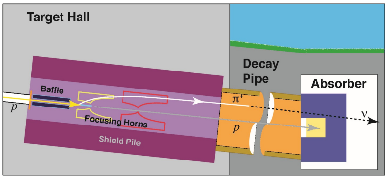
G4LBNF is highly configurable to facilitate studies of a variety of beam options. For the fluxes provided here, it was configured to simulate the reference beam described in detail in Annex 3A of the CDR[8], and the “optimized” design summarized in section 3.7.2 of Volume 2[2]. The reference beam design is based on the design of the target and focusing system for NuMI[9]. The baffle is a 1.5-m graphite cylinder, which protects downstream equipment in the case of a mis-steered beam. The graphite target is 95 cm long, corresponding to two interaction lengths. The target is surrounded by the first horn and followed by the second horn, each of which has a parabolic geometry and is operated at a current of 230 kA. The 194-m decay pipe is filled with helium and is followed by an absorber. A cartoon of the neutrino beamline is shown in Fig. 1. In the optimized design, a genetic algorithm is employed to determine values for 20 beamline parameters describing the primary proton momentum, target dimensions, and horn shapes, positions, and current that maximize sensitivity to CP violation in DUNE. Further optimization of the beam design following this approach is ongoing in the collaboration.

Both the optimized and reference geometries include a detailed description of the target, baffle, decay pipe, hadron absorber, and shielding. The reference geometry also includes a detailed description of both focusing horns, including welds and spider support. The optimized geometry uses a simplified model of the focusing horns. The basic output of G4LBNF is a list of all particle decays to neutrinos that occur anywhere along the beamline. Weights (historically referred to as “importance weights”) are used to reduce the size of the output files by throwing out a fraction of the relatively common low-energy neutrinos while preserving less numerous high-energy neutrinos. To produce neutrino flux distributions at a particular location, all of the neutrinos in the G4LBNF output file are forced to point toward the specified location and weighted according to the relative probability that the decay in question would produce a neutrino in that direction[10].
For each beam option, fluxes are provided at the center of the near detector (ND), located 459 m downstream of the start of Horn 1, and at the far detector (FD), located 1297 km downstream of the start of Horn 1. Fluxes are available for both neutrino mode (FHC) and antineutrino mode (RHC). Each flux is available in two formats: a root file containing flux histograms and a GLoBES flux input file. The root files also contain neutral-current and charged-current spectra, which are obtained by multiplying the flux by GENIE 2.8.4 inclusive cross sections. The flux histograms in the root files have units of neutrinos//POT. Note that these histograms have variable bin widths, so discontinuities in the number of events per bin are expected. The GLoBES files have units of neutrinos/GeV//POT. These text files are in the standard GLoBES format, in which the seven columns correspond to: .
3 Fast MC Simulation
As described in the DUNE CDR, the LArTPC performance parameters that go into the sensitivity calculations are generated using the DUNE Fast Monte Carlo (MC) simulation, which is described in detail in [11]. The Fast MC combines the simulated flux, the GENIE neutrino interaction generator [12], and a parameterized detector response that is used to simulate the reconstructed energy and momentum of each final-state particle. The detector response parameters used to determine the reconstructed quantities are summarized in Table 1. The assumptions on detector response used in the Fast MC are preliminary, and are expected to improve as the full detector simulation advances and more information on the performance of LArTPC detectors becomes available. The simulated energy deposition of the particles in each interaction is then used to calculate reconstructed kinematic quantities (e.g., the neutrino energy). Event sample classifications ( CC-like, CC-like, or NC-like), including mis-identification rates, are determined by the identification of lepton candidates. Lepton candidates are selected based on a variety of criteria including particle kinematics, detector thresholds, and probabilistic estimates of particle interaction final states. To reduce the neutral-current (NC) and charged-current (CC) backgrounds in the and CC-like samples, additional discriminants are formed using reconstructed transverse momentum along with reconstructed neutrino and hadronic energy as inputs to a k-Nearest-Neighbor (kNN) machine-learning algorithm. Plots showing the true-to-reconstructed smearing matrices, the analysis selection efficiencies, and the expected far detector event spectra generated by the Fast MC are available in [2].
| Particle type | Detection | Energy/Momentum | Angular |
|---|---|---|---|
| Threshold (KE) | Resolution | Resolution | |
| 30 MeV | Contained track: track length | 1∘ | |
| Exiting track: 30% | |||
| 100 MeV | -like contained track: track length | 1∘ | |
| -like contained track: 5% | |||
| Showering or exiting: 30% | |||
| e±/ | 30 MeV | 2% 15%/[GeV] | 1∘ |
| p | 50 MeV | p400 MeV/c: 10% | 5∘ |
| p400 MeV/c: 5% 30%/[GeV] | |||
| n | 50 MeV | 40%/[GeV] | 5∘ |
| other | 50 MeV | 5% 30%/[GeV] | 5∘ |
4 GLoBES Configuration
The GLoBES configuration summarizing the result of the Fast MC analysis and facilitating user-generated sensitivities is provided in the ancillary files in directory DUNE_GLoBES_Configs/; the flux included in this configuration is for the Optimized Beam described in Section 2, but it is valid to substitute the Reference Beam leaving the rest of the configuration unchanged. The flux normalization factor is included in GLoBES AEDL file to ensure that all variables have the proper units; its value is @norm=1.017718e17. Cross-section files describing charged-current and neutral-current interactions with argon, generated using GENIE 2.8.4, are included in the configuration. These cross-section text files are in the standard GLoBES format, in which the seven columns correspond to: , where . The true-to-reconstructed smearing matrices and selection efficiency as a function of energy produced by the Fast MC for various signal and background modes used by GLoBES are included. The naming convention for the channels defined in these files is summarized in Table 2.
| Name Includes | Process | Description |
|---|---|---|
| Appearance Mode: | ||
| app_osc_nue | (CC) | Electron Neutrino Appearance Signal |
| app_osc_nuebar | (CC) | Electron Antineutrino Appearance Signal |
| app_bkg_nue | (CC) | Intrinsic Beam Electron Neutrino Background |
| app_bkg_nuebar | (CC) | Intrinsic Beam Electron Antineutrino Background |
| app_bkg_numu | (CC) | Muon Neutrino Charged-Current Background |
| app_bkg_numubar | (CC) | Muon Antineutrino Charged-Current Background |
| app_bkg_nutau | (CC) | Tau Neutrino Appearance Background |
| app_bkg_nutaubar | (CC) | Tau Antineutrino Appearance Background |
| app_bkg_nuNC | X (NC) | Neutrino Neutral Current Background |
| app_bkg_nubarNC | X (NC) | Antineutrino Neutral Current Background |
| Disappearance Mode: | ||
| dis_bkg_numu | (CC) | Muon Neutrino Charged-Current Signal |
| dis_bkg_numubar | (CC) | Muon Antineutrino Charged-Current Signal |
| dis_bkg_nutau | (CC) | Tau Neutrino Appearance Background |
| dis_bkg_nutaubar | (CC) | Tau Antineutrino Appearance Background |
| dis_bkg_nuNC | X (NC) | Neutrino Neutral Current Background |
| dis_bkg_nubarNC | X (NC) | Antineutrino Neutral Current Background |
The GLoBES configuration provided in the ancillary files corresponds to 300 kt-MW-years of exposure: 3.5 years each of running in neutrino (FHC) and antineutrino (RHC) mode with a 40-kt fiducial mass far detector, in an 80-GeV, 1.07 MW beam. The and signal modes have independent normalization uncertainties of 2% each, while the and signal modes have independent normalization uncertainties of 5%. The background normalization uncertainties range from 5% to 20% and include correlations among various sources of background; the correlations among the background normalization parameters can be seen by looking at the @sys_on_multiex_errors_bg parameters in the AEDL file. The choices for signal and background normalization uncertainties may be customized by changing the parameter values in the file definitions.inc. The treatment of correlation among uncertainties in this configuration requires use of GLoBES version 3.2.16, available from the GLoBES website[13].
The sensitivity calculations presented in the CDR use oscillation parameters and uncertainties based on the NuFit 2014[14] fit to global neutrino data. These central values and relative uncertainties are provided in Table 3. In all cases, oscillation parameters are allowed to vary in the sensitivity calculations, constrained by Gaussian prior functions. The matter density is constant and equal to the average matter density for this baseline from the PREM[15, 16] onion shell model of the earth; the uncertainty on the density is taken to be 2%. The GLoBES minimization is performed over both possible values for the octant and, in the case of CP violation sensitivity, both possible values for the neutrino mass hierarchy. Figure 2 shows the DUNE sensitivity to determination of the neutrino mass hierarchy and discovery of CP violation, based on the configurations provided here, assuming an exposure of 300 kt-MW-years.
| Parameter | Central Value | Relative Uncertainty |
|---|---|---|
| 0.5843 | 2.3% | |
| (NH) | 0.738 | 5.9% |
| (IH) | 0.864 | 4.9% |
| 0.148 | 2.5% | |
| 7.5 eV2 | 2.4% | |
| (NH) | 2.457 eV2 | 2.0% |
| (IH) | -2.449 eV2 | 1.9% |


5 Far Detector GDML
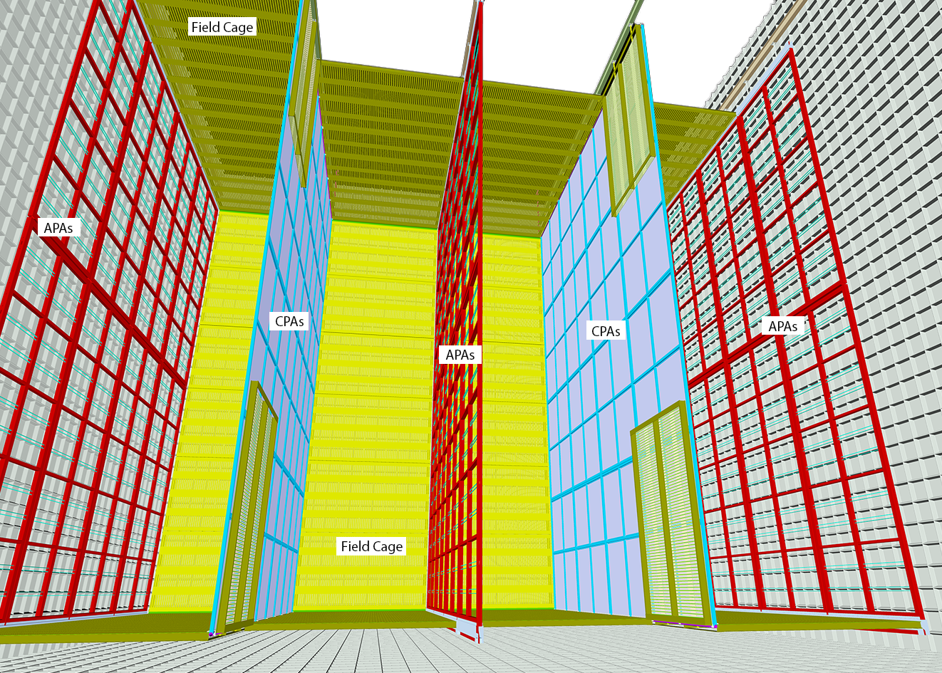
The DUNE far detector (FD) is described in detail in Volume 4 of the DUNE CDR. The reference design consists of four 10-kt fiducial mass, single-phase LArTPC modules with integrated photon detection systems. The active volume of one of these far detector modules is 12 m high, 14.5 m wide, and 58 m long; this is instrumented with 150 anode-plane assemblies (APAs), each of which has 2560 sense wires arranged in three wire planes and 200 cathode plane assemblies (CPAs). The TPC is located inside a cryostat vessel which also contains field-cage modules to enclose the four open sides between the anode and cathode planes. Figure 3 is a schematic showing the partially-installed detector.

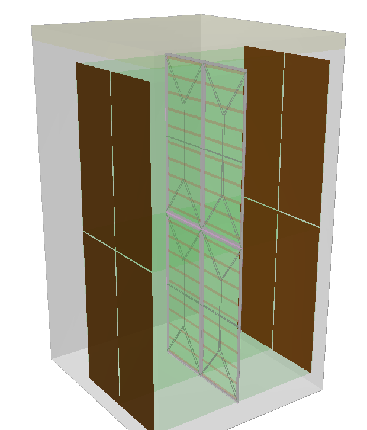
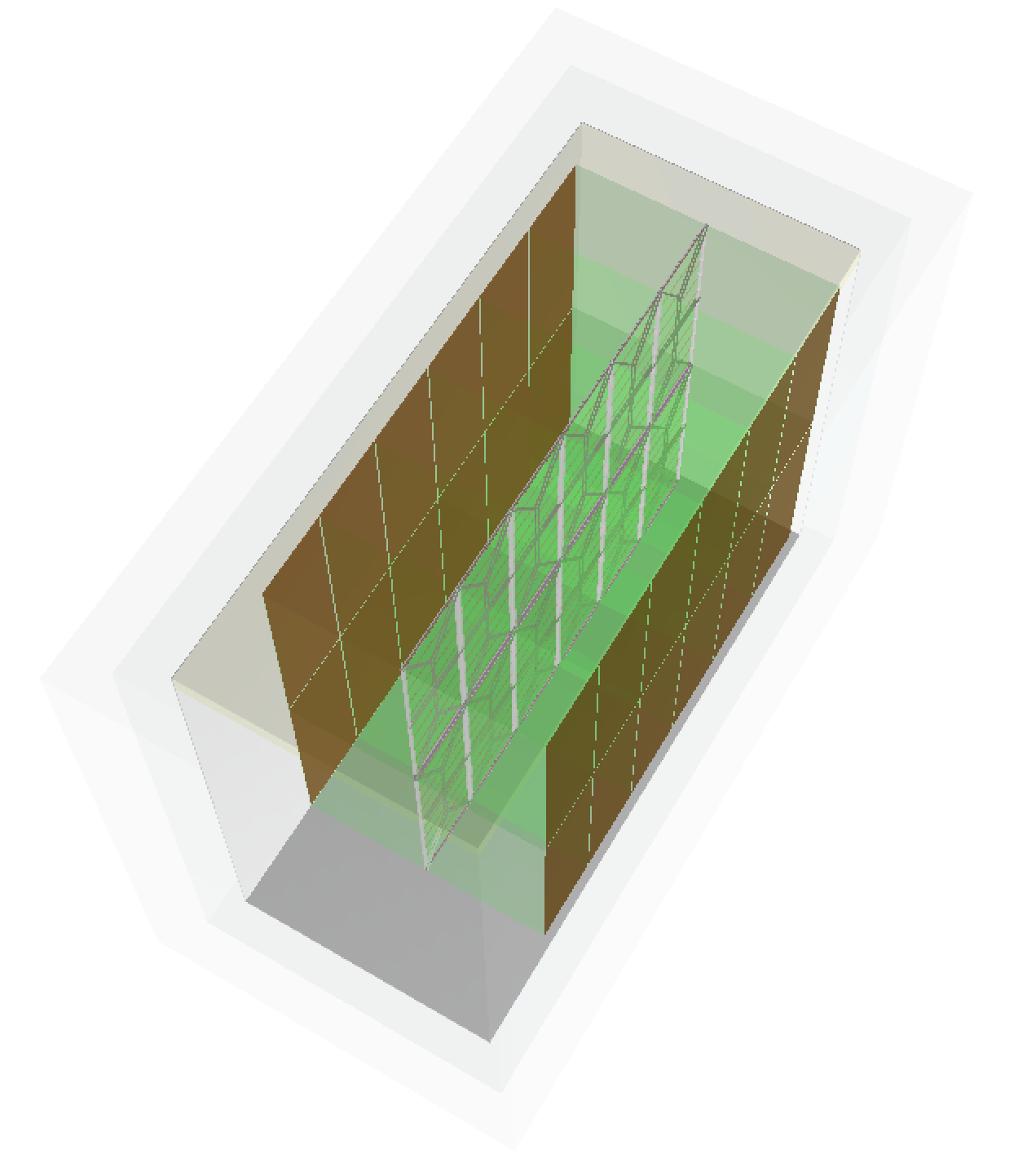
Simulating the nearly 400k channels in a single FD cryostat is extremely costly, so most simulation studies are performed in a smaller “workspace geometry” consisting of only a few APAs. The smallest (dune10kt_v1_workspace.gdml) is shown in the left image of Fig. 4 and consists of 4 APAs in the center of the cryostat, two stacked vertically by two end-to-end, with 4 corresponding CPAs at either end of opposing drift volumes. One feature of the APA is that one set of APA channels reads out the volume on both sides, with the opposite drift directions. Providing an active volume 12 m tall, 7 m wide from CPA to APA to CPA, and 4.6 m long in the beam direction, this is the smallest geometry which can still support studies involving gaps between vertically stacked and longitudinally adjacent APAs. Studies that rely on muon versus hadron track length, however, need to use the next largest geometry (dune10kt_v1_1x2x6.gdml), shown in the right image of Fig. 4, which has six APAs in the beam direction, providing 14 m of active LAr in the beam direction. One feature of these workspace configurations is that the CPAs are on the outside so that the drift volume on both sides of the APA can be used, whereas the actual FD design places the APAs on the outside, with the volume on the outer side not active. The GDML files are overwhelmingly dominated by the wire description, so versions of the files that do not include the wires are also included. These “nowires” files are especially useful for more efficient Geant4 tracking and for stand-along Geant4 studies, as LArSoft is needed to map sense wires to the proper channels.


The GDML files for the two FD workspace geometries described here, with and without the APA sense wires, are provided in the ancillary files in directory DUNE_GDML/. These geometry descriptions may be used in conjunction with LArSoft[17] to perform a Monte Carlo simulation of the DUNE far detector. Note that the full DUNE far detector simulation is under development and that this simulation was not used to produce the sensitivities presented in the DUNE CDR.
6 Summary
The results of simulations of the LBNF neutrino beamline and a parameterized Fast Monte Carlo of the DUNE Far Detector are provided to facilitate phenomenological studies of DUNE physics sensitivity. GDML files for simulation of the DUNE single-phase far detector for use in LArSoft simulations are also provided. The DUNE collaboration welcomes those interested in studying DUNE to join the collaboration or to use these configurations independently. Discussion of of any results with the DUNE collaboration, either as a member or a guest, is encouraged. The collaboration requests that any results making use of the ancillary files reference this arXiv posting and Volume 2 of the DUNE CDR[2].
References
- [1] DUNE Collaboration, (2016), arXiv:1601.05471.
- [2] DUNE Collaboration, (2015), arXiv:1512.06148.
- [3] DUNE Collaboration, (2016), arXiv:1601.02984.
- [4] P. Huber, M. Lindner, and W. Winter, Comput.Phys.Commun. 167, 195 (2005), hep-ph/0407333.
- [5] P. Huber, J. Kopp, M. Lindner, M. Rolinec, and W. Winter, Comput.Phys.Commun. 177, 432 (2007), hep-ph/0701187.
- [6] GEANT4, S. Agostinelli et al., Nucl. Instrum. Methods A, 250 (2003).
- [7] GEANT4, J. Allison et al., IEEE Trans. Nucl. Sci. 53, 270 (2006).
- [8] LBNF/DUNE Collaborations, http://lbne2-docdb.fnal.gov/cgi-bin/ShowDocument?docid=10686&asof=2015-7-14.
- [9] K. Anderson et al., (1998), http://inspirehep.net/record/493191/files/fermilab-design-1998-01.pdf.
- [10] Z. Pavlovic, Dissertation: Measurement of neutrino oscillations with the MINOS detectors in the NuMI beam, 2009, http://minos-docdb.fnal.gov/cgi-bin/ShowDocument?docid=5694.
- [11] LBNE, C. Adams et al., The Long-Baseline Neutrino Experiment: Exploring Fundamental Symmetries of the Universe, arXiv:1307.7335 [hep-ex], 2013.
- [12] C. Andreopoulos et al., Nucl. Instrum. Meth. A614, 87 (2010), 0905.2517.
- [13] GLoBES, https://www.mpi-hd.mpg.de/personalhomes/globes/.
- [14] M. Gonzalez-Garcia, M. Maltoni, and T. Schwetz, JHEP 1411, 052 (2014), 1409.5439.
- [15] A. M. Dziewonski and D. L. Anderson, Phys. Earth Planet. Interiors 25, 297–356 (1981).
- [16] F. D. Stacey, Physics of the earth, Second ed. (Wiley, 1977).
- [17] The LArSoft Collaboration, http://larsoft.org.