Inhomogeneous Josephson junction chains: a superconducting meta-material for superinductance optimization
Abstract
We report a theoretical study of the low-frequency impedance of a Josephson junction chain whose parameters vary in space. Our goal is to find the optimal spatial profile which maximizes the total inductance of the chain without shrinking the low-frequency window where the chain behaves as an inductor. If the spatial modulation is introduced by varying the junction areas, we find that the best result is obtained for a spatially homogeneous chain, reported earlier in the literature. An improvement over the homogeneous result can be obtained by representing the junctions by SQUIDs with different loop areas, so the inductances can be varied by applying a magnetic field. Still, we find that this improvement becomes less important for longer chains.
1 Introduction
Quantum engineering in superconducting nanocircuits is a rapidly developing field, due to progress in sample fabrication techniques which has been occurring in the past decade Jung2014 Complex circuits with many elements can be routinely fabricated on a chip nowadays. Due to superconductivity, electromagnetic signals propagate in such circuits with extremely low losses, and the circuit properties can be tuned by applying an external magnetic field. Highly inductive elements are often needed in such nanocircuits, to realize a large non-dissipative impedance. Applications of large inductances include protection of fluxonium qubits from the charge noise Manucharyan2009 , tunable microwave impedance matching Altimiras2013 , or a potential implementation of the electrical current standard in quantum metrology based on Bloch oscillations Likharev1985 ; Mooij2006 ; Guichard2010 .
Because any geometrical inductor (a coil being the standard textbook example) also necessarily possesses a parasitic self-capacitance which starts to dominate at high frequencies, its non-dissipative impedance is limited by the vacuum impedance, , where is the fine structure constant, and is the resistance quantum Feynman . Indeed, the inductance of a geometrical inductor is due to the magnetic field produced by the current, which acts on the current itself. The relativistic nature of this effect is the intrinsic reason for its weakness. This limitation can be overcome by using superconducting materials whose inductance is due to the kinetic energy of the Cooper pair condensate Tinkham , and thus is of non-relativistic origin. The term “superinductance” is often used to denote such superconductivity-based inductance.
Several structures, based on Josephson junctions (JJs), have been reported to work as superinductors Masluk2012 ; Bell2012 . In the first one, a large inductance was obtained by putting Josephson junctions in series, which gave the total inductance ( is the inductance of a single junction). In Ref. Bell2012 , magnetic-field-induced frustration was used to increase the inductance, which then exhibited a strong nonlinearity. Here, we focus on the linear case, and analyze structures analogous to that of Ref. Masluk2012 .
A simple strategy to increase the total inductance of a JJ chain would then be to make and/or as large as possible. However, in either case one faces some limitations. In the first case, the JJ inductance is inversely proportional to the Josephson energy of the junction, . To work as an inductor, the junction must be in the superconducting regime, , where the charging energy is determined by the junction capacitance. This condition sets a lower limit on , or, equivalently, an upper limit , or a lower limit on the junction area , as both .
Limitations on the junction number arise from the dependence of the chain response on the frequency . The phase slip rate, although exponentially suppressed for , grows with , giving rise to a finite dc resistance, which spoils the purely inductive response of the chain at low frequencies. From the high-frequency side, the effective bandwidth of the inductive response is restricted by electromagnetic modes supported by the chain, (the lowest mode frequency). Crucially, besides the capacitance of the junction between neighboring superconducting islands, each island has a small capacitance to the ground. This capacitance gives rise to screening of the Coulomb interaction between the islands on a length scale and produces an acoustic-like region of the mode dispersion of spatially homogeneous chains, where , and is the wavenumber, (Fig. 1). The first mode corresponds to , so for large , the frequency of the lowest mode , and the inductive response bandwidth shrinks with increasing . This was the main limitation for the device studied in Ref. Masluk2012 , where a special effort was made to decrease the parasitic ground capacitance .

The above argumentation works for spatially homogeneous chains, whose total inductance is determined by just two parameters, the single-junction inductance and their number , if is assumed to be the same for all junctions. This, however, need not be the case, since an arbitrary spatial profile of junction sizes along the chain can be produced during the sample fabrication. A spatial modulation of junction parameters modifies the normal modes of the chain, and can manifest itself in various situations. For example, Josephson energy renormalization by coupling to the normal modes was shown to be affected by a modulation of the chain parameters Taguchi2015 . Effect of the normal mode structure on dephasing of the fluxonium qubit was discussed in Ref. Viola2015 . For the present problem, one can try to optimize the total inductance and the operation bandwidth of the chain using many more degrees of freedom than just and , because the parameters of each of the junctions can be treated as optimization variables. To study, whether one can take advantage of this large number of variables and improve the homogeneous chain result of Ref. Masluk2012 by carefully choosing the spatial profile of the junction parameters, is the purpose of the present work.
In this paper, we consider two ways to introduce a spatial inhomogeneity into the structure. One is to vary the area of each junction (assuming the island area to be already optimized to minimize the ground capacitance as was done in Refs. Manucharyan2009 ; Masluk2012 ; Manucharyan2012 ). This leads to a simultaneous variation of the junction inductances and capacitances , such that their product . Optimizing over all areas , we find that the best result is still achieved for a homogeneous configuration.

The second way to introduce a spatial variation of the junction parameters is to represent each junction by a SQUID (superconducting quantum interference device). When subject to a magnetic field , a SQUID behaves like an effective Josephson junction with a field-dependent Josephson energy , where is the superconducting flux quantum, and is the SQUID loop area which determines the magnetic flux through the SQUID (Fig. 2). Then, if all SQUIDs have different areas , the inductance of each junction of the chain, , varies in space, and this variation is independent of the variation of the capacitance (the latter is controlled by the junction area , independent of the loop area ). In this case, we show that one can indeed improve over the homogeneous result, by placing SQUIDs with larger loop area (higher inductance) near the ends of the chain. Still, the obtained improvement over the homogeneous result turns out to decrease with the increasing chain length.
2 Formal setting of the optimization problem
We consider a chain of superconducting islands. Each island is connected to its nearest neighbors by Josephson junctions, so the chain has junctions (Fig. 3). We assume . When the junctions are in the superconducting regime, , the oscillations of the superconducting phase on each island are small. Then, the Josephson current through the th junction from island to can be written as Tinkham . Here, is the junction critical current. Thus, the voltage drop across the junction can be determined by using the Josephson relation:
| (1) |
This expression shows that the junction behaves as a linear inductor, and the Josephson kinetic inductance is given by . In addition, we assume that the dissipation is very small and can be neglected. Then, an isolated chain is equivalent to the electric circuit shown in Fig. 3(b), where is the capacitance formed by the neighboring superconducting islands, and is the capacitance of each island to ground. We define the complex impedance of the chain at frequency as the ratio of the voltage on an external ac voltage source, connected to the islands and , to the current through this source (Fig. 3).

To determine the normal mode frequencies of this circuit, one can apply the Kirchhoff’s law at each of the nodes of this circuit. This gives the following system of linear equations for the voltages :
| (2a) | |||
| (2b) | |||
| (2c) | |||
where the junction admittance is defined as
| (3) |
System (2) can be written in the matrix form, , in terms of the column vectors and , as well as the corresponding matrix . Then the chain impedance can be expressed in terms of the matrix elements of the inverse as . At low frequencies, the admittances are dominated by the inductive part, so the impedance is given by , where is the total inductance of the chain,
| (4) |
The approximation is valid as long as , where is the lowest normal mode frequency, for which .
As discussed in the introduction, ideally one would like to increase both and , but these two requirements are in conflict. Thus, one can try to maximize at fixed , or maximize while keeping fixed. We prefer the second option, as the constraint expressed by Eq. (4) is much easier to resolve than the constraint . Thus, our optimization problem is formulated as follows: find the spatial profile of which maximizes while keeping fixed. To complete the formulation of the problem, we have to specify the independent variables over which the optimization is performed.
The shape and size of the superconducting islands and of the junctions between them can be well controlled in the fabrication process. It is easy to notice that while the parameters are mostly determined by the junction areas, the parasitic ground capacitances are mostly determined by the island sizes. Thus, the first obvious step is to minimize the island sizes as much as possible while keeping constant the junction areas, as any part of the island area which does not participate in the junctions, does not contribute to the inductance, but decreases . This optimization was performed in Refs. Manucharyan2009 ; Masluk2012 ; Manucharyan2012 ; ManucharyanThesis . Then, the ground capacitance of the th island becomes a function of the areas of the junctions in which it particpates, and . This function was calculated numerically in Ref. Masluk2012 , and the resulting dependence resembles a weak power law or a logarithm. We will assume that this first optimization step has been performed.
Then, our first setting corresponds to independent variation of all junction areas, which are allowed to vary in a certain range. In the fabrication process, quite a wide range of sizes can be achieved, and the restriction on the areas rather comes from physical considerations. One restriction is that for too small areas, the condition is violated, and then the classical description of small phase oscillations is no longer valid. Indeed, the amplitude of a quantum phase slip, Matveev2002 is exponentially suppressed only for small junction impedances, (we remind that denotes the resistance quantum), so too large impedances are not allowed. The junction impedance is inversely proportional to its area, so the area cannot be made too small. On the other hand, if the junction area is too large, the junction can no longer be treated as a zero-dimensional object, because the frequency of its own electromagnetic modes becomes too low.
Let us choose the smallest allowed junction area as the unit of area. Then the largest allowed junction area is an independent dimensionless parameter of the problem. The junction inductance and capacitance at the smallest area, and , can be chosen as the units of inductance and capacitance, respectively. Thus, we have dimensionless variables , allowed to vary in the range
| (5a) | |||
| They determine the inductance and the capacitance of each junction as | |||
| (5b) | |||
| and Eq. (4) thus imposes a constraint on the set . In this case, the plasma frequency of each junction is unchanged, . Finally, for the ground capacitances we use a simple form | |||
| (5c) | |||
where is some function, growing sublinearly with (a power law or a logarithm). All qualitative arguments given below are not sensitive to the specific dependence ; in the numerical calculations, we set , as mentioned in Ref. ManucharyanThesis . To define Eq. (5c) at the ends, we set , . Thus, the first optimization problem is fully defined as maximization of determined from Eqs. (2), whose coefficients are expressed by Eqs. (5b) and (5c) in terms of the dimensionless areas . The optmization variables are the areas in the allowed range (5a) and subject to constraint (4), as well as the number of the junctions itself. Note that constraint (4) and inequalities (5a) restrict the number of junctions to the interval
| (6) |
The second way of producing a spatial variation of the JJ chain parameters is to replace each junction by a SQUID. Each SQUID is characterized by its loop area , independent of the junction area (Fig. 2). By applying a magnetic field , one can change the SQUID inductance as
| (7) |
where the zero-field inductance is determined by the junction area . This way of tuning the properties of the JJ by magnetic field is routinely used in experiments (see, e. g., Ref. Weissl2015 ). Here, it is crucial for us that the spatial variation of inductance is independent of that of capacitance, which was not the case in the previous model, since in Eq. (5b) the product remained fixed. Thus, instead of the optimization problem defined by Eqs. (5a)–(5c) via variables , we consider another problem defined via variables :
| (8a) | ||||
| (8b) | ||||
All junction areas are assumed to be the same, , so the plasma frequency of each SQUID is modulated as , and each variable represents the ratio
| (9) |
where is some maximal magnetic flux allowed to pierce the SQUID loops in order for the device to remain in the superconducting regime . Clearly, are independent variables, because are independent, and additional freedom is introduced by the magnetic field. Just like before, the only constraint on is Eq. (4), and it restricts the chain length to the interval
| (10) |
3 Junction area modulations
Before we proceed with optimization for inhomogeneous JJ chains, it is useful to see what can be achieved in the homogeneous case, for future reference. For the problem (5a)–(5c), with all , we have only two variables, and . Constraint (4) fixes , , , . It is convenient to denote the first mode frequency for this homogeneous chain by . It is given by Masluk2012
| (11) |
for . This is a decreasing function of for any growing slower than linearly with . Thus, is maximized by taking , all . We denote the corresponding value of by .
To improve this result using an inhomogeneous chain, one should take some [a smaller one would be incompatible with the constraint (4)], and hope that the gain in from the inhomogeneiety would overcome the loss due to the length increase. A qualitative idea of the best spatial profile can be obtained from the perturbation theory for system (2), developed in Ref. Basko2013 . Let us use the homogeneous chain of length with all and the first mode frequency as the zero approximation. If we now modify each junction area by a small amount , the first-order frequency shift is given by Basko2013
| (12a) | ||||
| (12b) | ||||
The dependence of on is quite simple (), and is the largest for , in the middle of the chain. The value at the maximum as long as , which is the case for any sublinear and . Thus, the center of the chain contributes the most to the increase of .
Let us take . Then, the largest increase of the areas near the center, allowed by constraint (4), is obtained by keeping junctions with , and two more junctions with , to be put in the center. (Note that it is impossible to keep junctions with , as the constraint would require the remaining one to have ). As the area change for the central junctions is not small, the perturbative Eq. (12a) is not sufficient to describe this situation. Still, for this structure can be found analytically. The result of this straightforward but bulky calculation, given in Appendix A:, is that the resulting frequency is always smaller than .
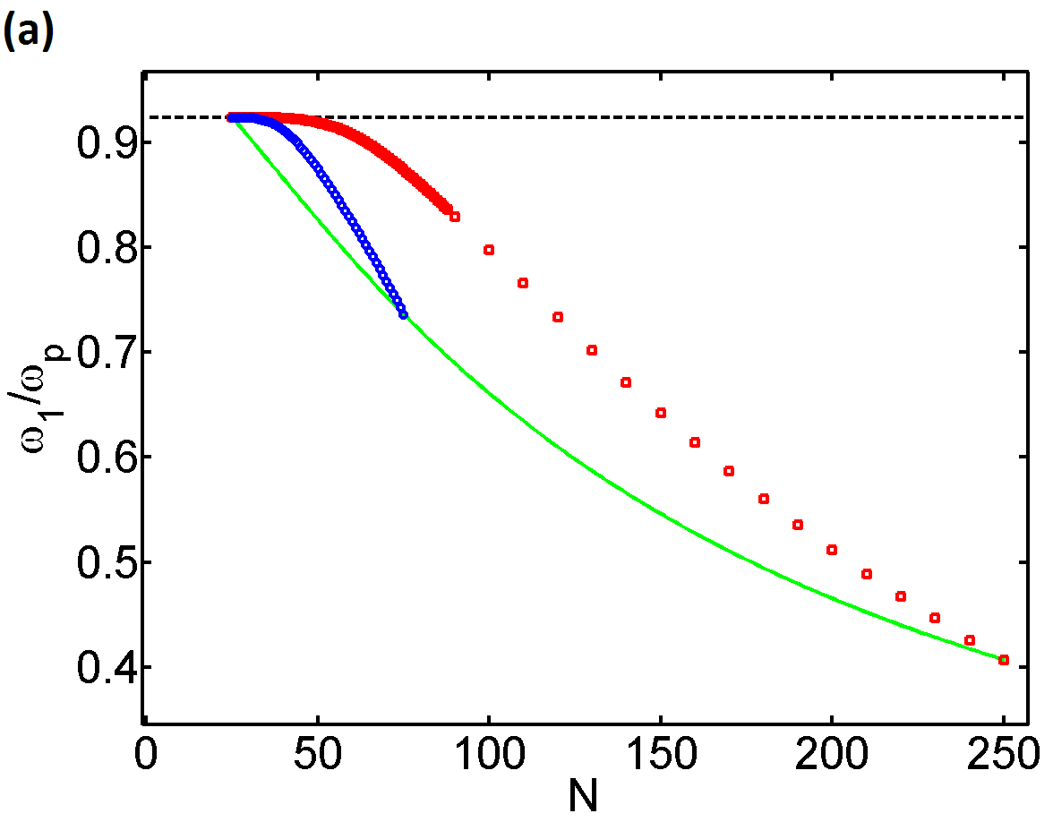
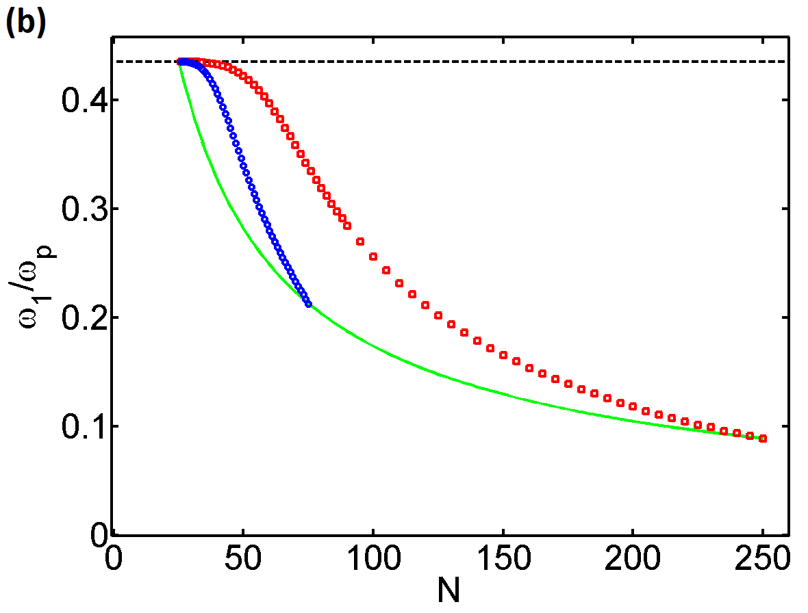
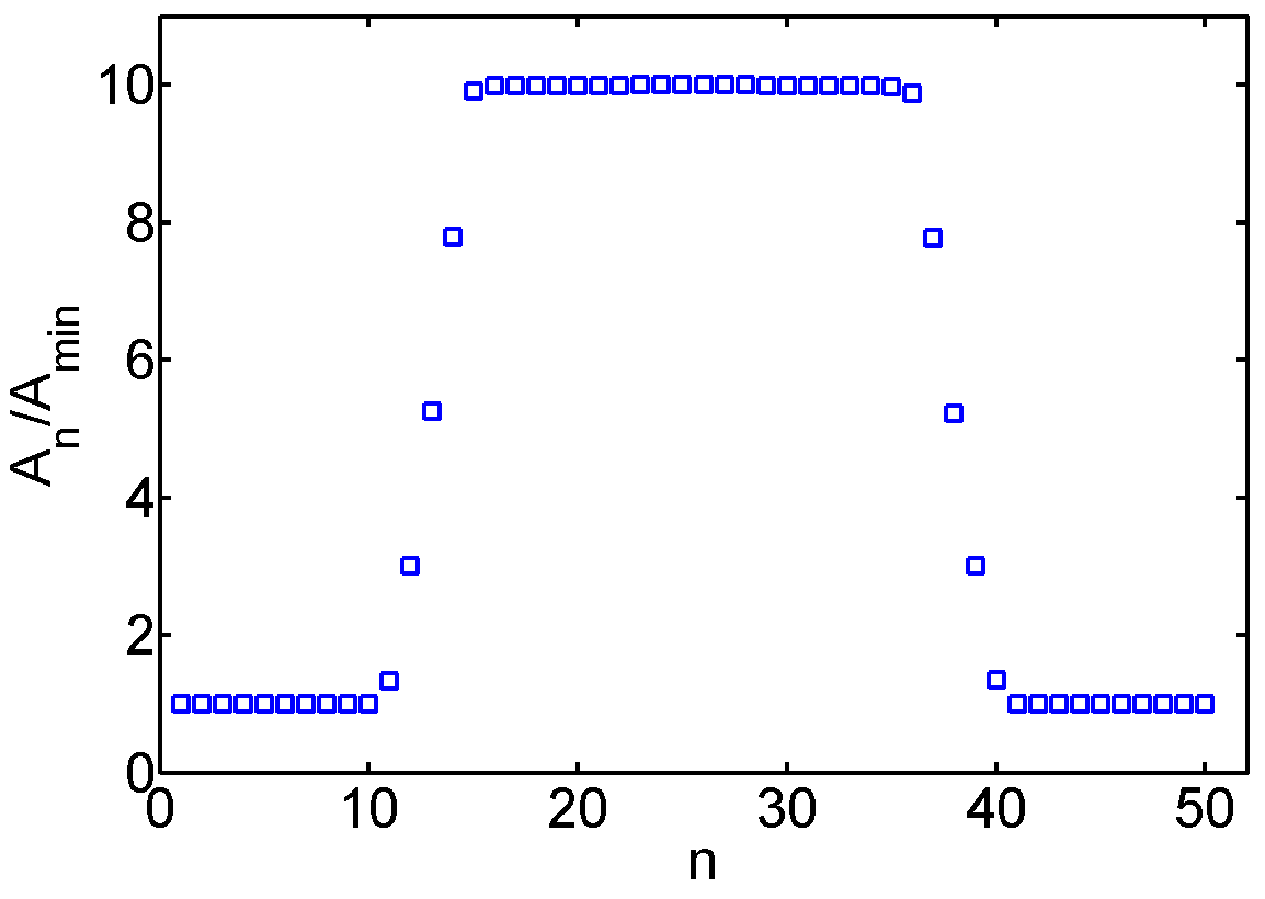
The full optimization of all junction areas , subject to constraint (4), can be performed numerically. For any , we maximize as a function of all the areas, calculated numerically from the eigenvalue equation . The resulting maximum is plotted versus in Fig. 4 for several values of and . The analytical result of Appendix A: shows that the curve starts to bend down at , and the numerics shows that the same trend is followed for all . Thus the optimal at is always below the best value for the homogeneous chain, . In Fig. 5 we show the optimal spatial profile , corresponding to one of the points in Fig. 4. Indeed, the best for a fixed is obtained by placing the largest junctions in the middle of the chain. Still, the resulting gain in is smaller than the loss due to the increase of the chain length from to .
4 SQUID loop area modulations
As in the previous section, we start by a straighforward study of the homogeneous case. Constraint (4) fixes , so for the chain with , , , assuming , instead of Eq. (3) we have
| (13) |
where is the screening length, which does not depend on and for problem (8b)–(8a). Expression (13) reaches maximum at , so we have to consider three cases for the position of this value with respect to the interval (10).
(i) In the case , the frequency is maximized by taking the longest possible chain, . This case corresponds to the regime when for all allowed the first mode is on the flat part of the mode dispersion curve (Fig. 1). This means that we have demanded a value of which is too small; a larger inductance can be obtained by simply increasing the length at almost no cost in . So, this case has no practical relevance.
(ii) When , the frequency is maximized at . This corresponds to the first mode frequency roughly at the boundary between the flat part of the mode dispersion curve and its acoustic part.
(iii) In the case , the frequency is maximized by taking the shortest possible chain. This regime corresponds to demanding such a large inductance that the first mode necessarily belongs to the acoustic part of the dispersion curve. This is the regime where the competition between and is the most severe; it is in this regime that a gain in by introducing a spatial variation of would be the most interesting for practical purposes.
The perturbation theory in small modulations with respect to a homogeneous chain with junctions gives a result, similar to Eq. (12a):
| (14) |
which again tells us that inductance modulations in the center of the chain contribute the most to the increase in . As in the previous section, we now consider a chain of length with inductances of two junctions in the center smaller by a factor . The explicit calculation of given in Appendix A: shows that this chain has , and thus one can indeed improve over the homogeneous result. However, for long chains, , the gain is quite small:
| (15) |
Is it possible to gain more in by choosing a chain length significantly exceeding ? As a trial spatial profile, let us consider a long chain with a central region of length where the inductances are smaller by a factor than in the surrounding (although this piecewise profile does not coincide with the true optimal one, found numerically below, it allows for a simple analytical solution):
| (16) |
Constraint (4) then fixes
| (17) |
For , we can study the problem in the continuum limit, replacing the junction number by a continuous variable . In addition, let us focus on the most interesting case of long chains , then one can approximate the mode dispersion by the acoustic one, . Then, Eqs. (2) are transformed into the Helmholtz equation with von Neumann boundary conditions at the ends of the chain,
| (18) |
For the piecewise function , given by Eq. (16), and for a given frequency , the wavenumbers in the outer regions and in the central region are given by and by , respectively. Thus, taking advantage of the symmetry of with respect to , we seek in the form (the first mode is odd)
| (19) |
The requirement of continuity of and at yields the following equation for :
| (20) |
For all , upon increasing from 0 to (that is, upon decreasing from to ), the solution monotonically rises from to (Fig. 6), the highest frequency being achieved in the shortest homogeneous chain. This means that in the limit the gain in is so small that it is not captured by the acoustic approximation.

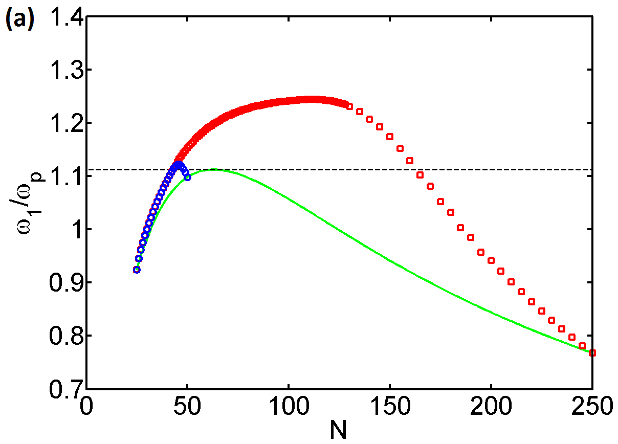
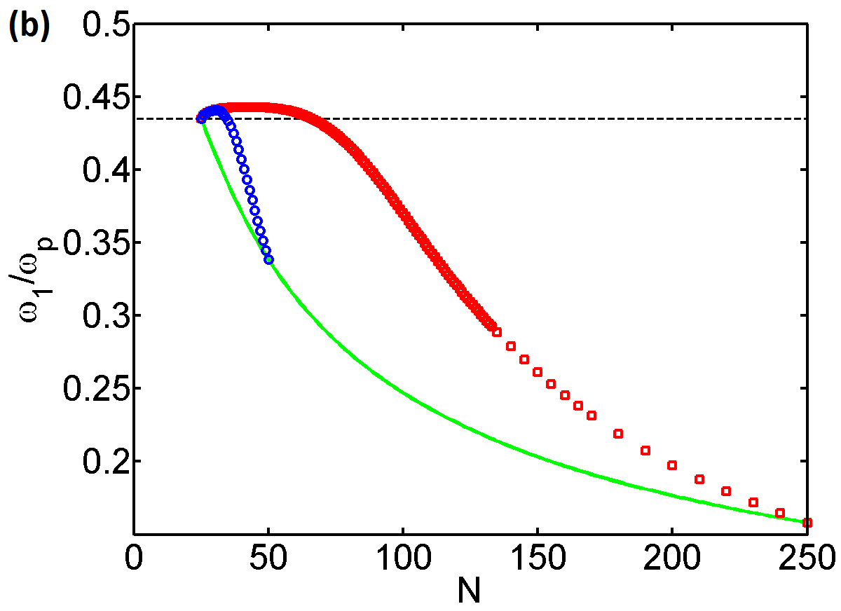
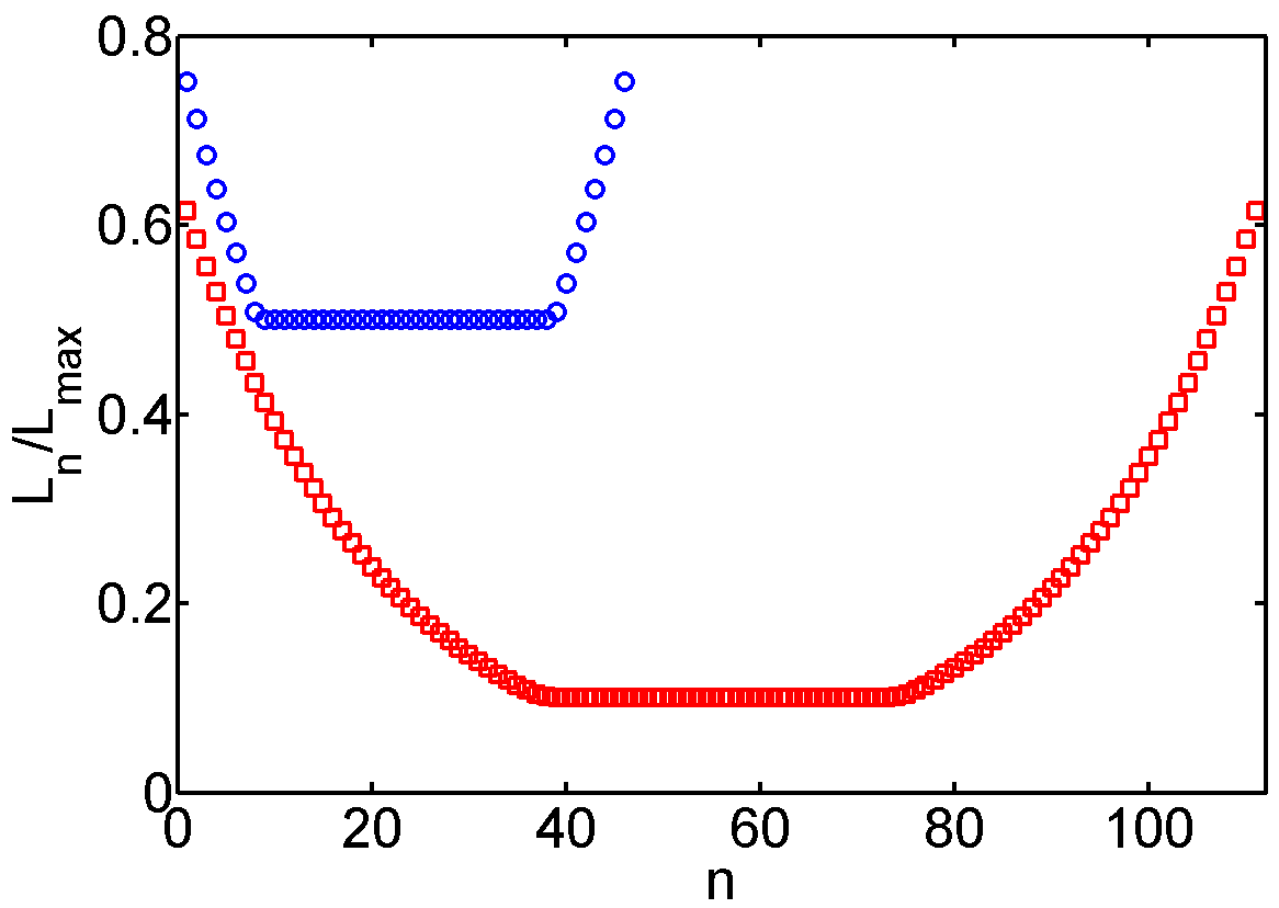
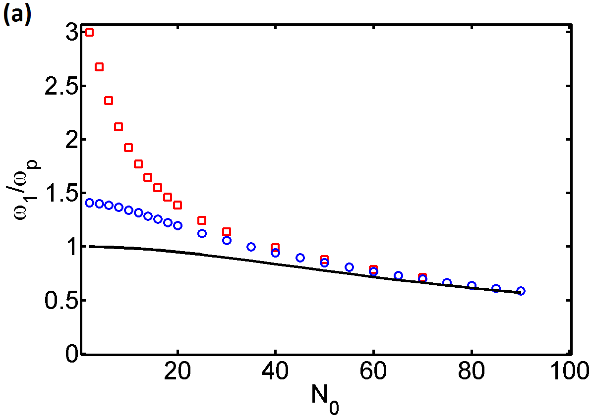
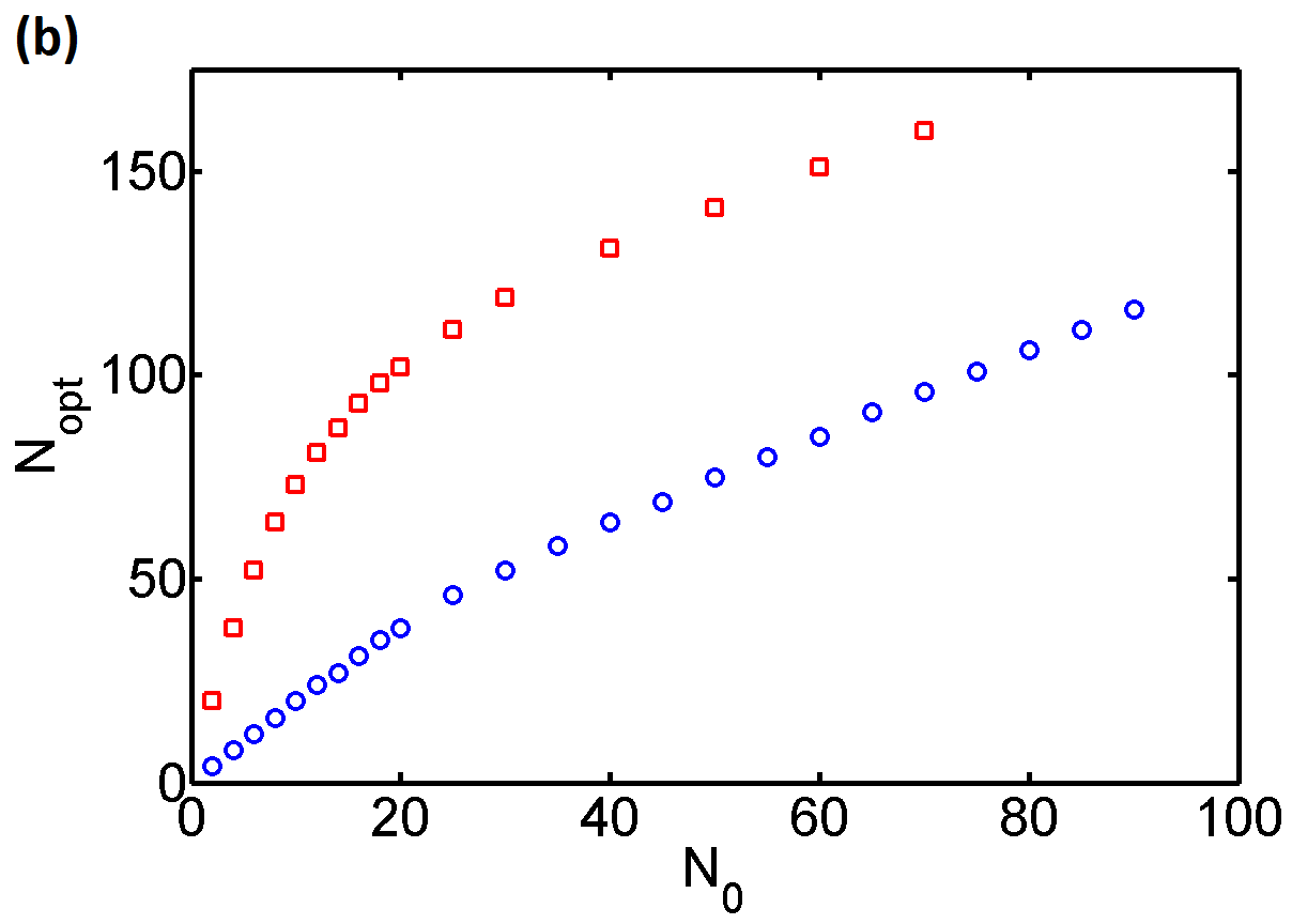
To check these considerations numerically, we perform the full optimization of all , subject to constraint (4). As in the previous section, for any , we maximize as a function of all the areas, calculated numerically from the eigenvalue equation . The resulting maximum is plotted versus in Fig. 7 for several values of and . The optimal spatial profile of the inductance is shown in Fig. 8; as in the previous section, it corresponds to putting the small-inductance junctions in the middle of the chain, and the large-inductance ones near the ends. From the analytical arguments above, we do not expect the first mode frequency for the optimal inhomogeneous chain of optimal length to be much larger than for the shortest homogeneous chain. This is checked numerically in Fig. 9(a), where we plot the two frequencies as a function of (we remind that at fixed , parametrizes the desired total inductance). For long chains, the improvement due to spatial modulation is indeed negligible. The optimal length of the modulated chain is close to at large (up to a constant offset), as shown in Fig. 9(b).
5 Conclusions
In this work, we explored the possibility to optimize the frequency range where a JJ chain can work as a superinductor, by a careful choice of the spatial profile of the junction parameters. In the case when junction areas are varied, the best result is still obtained for a spatially homogeneous chain, as in Ref. Masluk2012 . Another way to introduce a spatial variation is to represent the junctions by SQUIDs whose loop areas are different. Then, by applying a magnetic field, one can vary the junction inductance independently from its capacitance. We show that this strategy can indeed give an improvement with respect to the homogeneous case, if the most inductive junctions are placed near the ends of the chain, and the least inductive ones in the middle. Still, we find that this improvement becomes less important for longer chains.
The qualitative difference between the cases of junction area and SQUID loop area modulations stems from the fact that in the first case, the plasma frequency of each junction, , remains fixed. In the second case, the junction inductance can be decreased independently from the capacitance, which leads to an increase of the local plasma frequency, and to a certain degree increases the overall frequency scale.
Acknowledgements.
We are grateful to W. Guichard and F. Hekking for stimulating discussions and critical reading of the manuscript. We also acknowledge support from the European Research Council (Grant No. 306731).Appendix A: Chain with two central junctions modified
Let us start by deriving the dispersion relation for a homogeneous chain of junctions with parameters , , , and . Eq. (2) becomes
| (A.1) |
A plane wave, , with any and satisfies this equation, provided that
| (A.2) |
which gives the usual dispersion relation Masluk2012 ,
| (A.3) |
For a given , we seek the solution in the form , and substitute it into Eqs. (2a), (2c) at the ends of the chain, which play the role of the boundary conditions. These give, respectively,
| (A.4a) | |||
| (A.4b) | |||
The first of these equations requires the solution to have the form
| (A.5a) | |||
| while the second one imposes the form | |||
| (A.5b) | |||
with some and . Matching these expressions in the bulk of the chain, we obtain two possibilities, corresponding to even and odd modes with respect to reflection :
| (A.6a) | |||
| (A.6b) | |||
where is an integer. Thus, the even modes have , and the odd ones . Note that the first mode is odd.

Now, let us consider a chain with two central junctions modified. We assume to be even, , then we can again take advantage of the reflection symmetry, . In the homogeneous part of the chain we assume , and , while in the central region we set
| (A.7a) | |||
| (A.7b) | |||
| (A.7c) | |||
For the junction areas’ variation, considered in Sec. 3, we have to set , , . For the loop areas’ variation (Sec. 4), we have , . The reflection symmetry is preserved, so the modes can still be classified as even or odd, and by continuity we know that the first mode is odd. Thus, similarly to Eqs. (A.5a), (A.5b), we can seek in the form
| (A.8) |
with yet unknown which will be determined by matching the solutions in the middle of the chain. Note that as is related to the frequency by the dispersion relation (A.3), which is a monotonically increasing function, it is sufficient to check whether the value of , obtained by matching the solutions, is larger or smaller than the one corresponding to the shortest homogeneous chain, .
in the form (A.8) automatically satisfy the Kirchhoff laws for the nodes . The Kirchhoff laws for the remaining are identical, so we have one independent equation which determines :
| (A.9) |
where the frequency is related to by Eq. (A.3). Note that dropped out of the equation as . Eq. (LABEL:cosqN1=) can be identically rewritten as
or, equivalently, as
| (A.10) |
The left-hand side of this equation passes through zero precisely at , with a large negative slope. Thus, to find out whether the solution is larger or smaller than , we just need to check the sign of the right-hand side at .
When only junction areas , are varied, that is, and , the large factor drops out, so the right-hand side of Eq. (A.10) is necessarily positive, and thus . For the variation of SQUID loop areas only, we have , , which leads to . Note, however, that the difference is quite small:
| (A.11) |
References
- (1) P. Jung, A. V. Ustinov, S. M. Anlage, Supercond. Sci. Technol. 27, 073001 (2014)
- (2) V. E. Manucharyan, J. Koch, L. I. Glazman, M. H. Devoret, Science 326, 113 (2009)
- (3) C. Altimiras, O. Parlavecchio, P. Joyez, D. Vion, P. Roche, D. Esteve, F. Portier, Appl. Phys. Lett. 103, 212601 (2013)
- (4) K. K. Likharev, A. B. Zorin, J. Low Temp. Phys. 59, 347 (1985)
- (5) J. E. Mooij, Y. V. Nazarov, Nat. Phys. 2, 169 (2006)
- (6) W. Guichard, F. W. J. Hekking, Phys. Rev. B 81, 064508 (2010)
- (7) R. P. Feynman, R. B. Leighton, M. Sands, The Feynman Lectures on Physics, Vol. 2 (Addison-Wesley, Reading, MA, 1964)
- (8) M. Tinkham, Introduction to Superconductivity (McGraw-Hill Book Co., New York, 2004)
- (9) N. A. Masluk, I. M. Pop, A. Kamal, Z. K. Minev, M. H. Devoret, Phys. Rev. Lett. 109, 137002 (2012)
- (10) M. T. Bell, I. A. Sadovskyy, L. B. Ioffe, A. Y. Kitaev, and M. E. Gershenson, Phys. Rev. Lett. 109, 137003 (2012)
- (11) M. Taguchi, D. M. Basko, F. W. J. Hekking, Phys. Rev. B 92, 024507 (2015)
- (12) G. Viola, G. Catelani, Phys. Rev. B 92, 224511 (2015)
- (13) V. E. Manucharyan, N. A. Masluk, A. Kamal, J. Koch, L. I. Glazman, M. H. Devoret, Phys. Rev. B 85, 024521 (2012).
- (14) V. E. Manucharyan, Ph. D. Thesis (Yale University, 2012).
- (15) K. A. Matveev, A. I. Larkin, L. I. Glazman, Phys. Rev. Lett. 89, 096802 (2002).
- (16) T. Weißl, G. Rastelli, I. Matei, I. M. Pop, O. Buisson, F. W. J. Hekking, W. Guichard, Phys. Rev. B 91, 014507 (2015)
- (17) D. M. Basko, F. W. J. Hekking, Phys. Rev. B 88, 094507 (2013)