Straight Skeletons with Additive and Multiplicative Weights and Their Application to the Algorithmic Generation of Roofs and Terrains
Abstract
We introduce additively-weighted straight skeletons as a new generalization of straight skeletons. An additively-weighted straight skeleton is the result of a wavefront-propagation process where, unlike in previous variants of straight skeletons, wavefront edges do not necessarily start to move at the begin of the propagation process but at later points in time. We analyze the properties of additively-weighted straight skeletons and show how to compute straight skeletons with both additive and multiplicative weights.
We then show how to use additively-weighted and multiplicatively-weighted straight skeletons to generate roofs and terrains for polygonal shapes such as the footprints of buildings or river networks. As a result, we get an automated generation of roofs and terrains where the individual facets have different inclinations and may start at different heights.
keywords:
weighted straight skeleton , additive weights , multiplicative weights , roof , terrain , wavefront propagation1 Introduction
1.1 Motivation and prior work
Straight skeletons were introduced to computational geometry over 20 years ago by Aichholzer et al. [1]. Suppose that the edges of a simple polygon move inwards with unit speed in a self-parallel manner, thus generating mitered offsets inside of . Then the (unweighted) straight skeleton of is the geometric graph whose edges are given by the traces of the vertices of the shrinking mitered offset curves of , see Figure 1 and Section 2.
Multiplicatively-weighted straight skeletons were first mentioned by Aichholzer and Aurenhammer [2] and then by Eppstein and Erickson [3]. Roughly, the presence of multiplicative weights implies that the edges of are allowed to move inwards at different speeds. Recently, multiplicatively-weighted straight skeletons were studied in detail by Biedl et al. [4] who analyzed under which conditions properties of the unweighted skeleton carry over to the weighted pendant.
Unweighted and multiplicatively-weighted straight skeletons are known to have applications in diverse fields. Aurenhammer [5] investigates fixed-share decompositions of convex polygons using skeletons with specific positive multiplicative weights. Barequet et al. [6] employ multiplicatively-weighted straight skeletons as a theoretical tool for computing (unweighted) straight skeletons in three-space. Barequet and Yakersberg [7] morph shapes by means of their straight skeletons. Tomoeda and Sugihara use straight skeletons to create signs with an illusion of depth [8], and Sugihara also uses multiplicatively-weighted skeletons in the design of pop-up cards [9]. Haunert and Sester [10] apply them for topology-preserving area collapsing in geographic information systems (GIS). In another GIS application, Vanegas et al. [11] use straight skeletons for generating parcels in urban modeling.
The automatic generation of roofs of buildings based on straight skeletons of their footprints (i.e., bird’s eye view) has also received wide-spread attention in large-scale urban modeling. E.g., Larive and Gaildrat [12], Müller et al. [13], and Buron et al. [14] combine GIS data and shape grammars with production rules to generate roofs for buildings. As a starting point or if a purely grammar-based generation is not possible, they resort to roofs obtained from straight skeletons. The roofs in the recent work by Sugihara [15, 16] are based on straight skeletons as well. Furthermore, Laycock and Day [17] and Kelly and Wonka [18] use multiplicatively-weighted straight skeletons for modeling roofs in more realistic ways.
A problem closely related to the generation of roofs is the (re-)construction of terrains. For instance, we might be given a river map together with estimates of the slopes of the terrain. Straight skeletons offer a promising approach to both roof generation and terrain construction.
Roofs created by straight skeletons are limited to hip roofs and, with some postprocessing, gable roofs. Their ridges tend to be parallel to long edges of the footprint of the building. Typically, such roofs will not have ridges that are perpendicular to long (parallel) edges of the footprint.
1.2 Our contribution
We introduce an additively-weighted straight skeleton as a new generalization of straight skeletons: If additive weights are present then edges of the input need not all start to move at the same time. We analyze the properties of additively-weighted straight skeletons and show how to extend the standard algorithmic framework for computing straight skeletons (based on wavefront propagation) to additively-weighted straight skeletons.
We also argue that this framework allows to handle both additive and multiplicative weights. Multiplicative weights translate to different speed functions for the input edges, but each speed stays constant throughout the entire movement of the edge. As a matter of fact, in our framework any speed function that remains piecewise constant could be used for an edge, thus extending traditional straight skeletons even further.
The input for our algorithm need not be constrained to simple polygons. Rather, any so-called planar straight-line graph (PSLG) forms a permissible input. (A PSLG is a collection of straight-line segments that do not intersect pairwise except at common end-points.)
Combining both additive and multiplicative weights yields input edges that (1) are allowed to move at different speeds and (2) may start at different times. As a result, we get an automated generation of roofs or terrains where the individual facets have different inclinations and may start at different heights. In particular, additive weights allow for gable roofs without postprocessing, with the ridge being perpendicular to some long edge of the footprint. General piecewise constant speed functions result in piecewise linear surfaces (roof, terrain, etc.) where individual facets may have kinks.
As for unweighted straight skeletons, additively and multiplicatively weighted straight skeletons come with an important property: A raindrop that hits a facet of a surface generated by means of a weighted straight skeleton is guaranteed to run off. That is, no local minima can occur on the surface.
2 Preliminaries
Wavefront Propagation Process
Let denote a simple polygon. The straight skeleton of is defined by means of a wavefront propagation process. The wavefront is a set of wavefront polygons and changes with time . Initially, at time zero, consists only of . Then, as time increases, the edges of move towards the interior of at unit speed in a self-parallel manner, thereby preserving incidences. Thus, the vertices of move along the angular bisectors of polygon edges, and the wavefront corresponds to a mitered offset of , see Figure 1.

To maintain the planarity of the wavefront during the propagation process, Aichholzer et al. [1] resolve non-planarities when they occur:
-
1.
In an edge event, an edge of the wavefront has shrunk to zero length. This edge is removed from the wavefront, resulting in the two adjacent edges to become neighbors.
-
2.
In a split event, a reflex vertex reaches another part of the wavefront. (A vertex of is called reflex if the interior angle at is greater than , and convex if it is less than ; tangential vertices with interior angle equal to can be ignored during the wavefront propagation.) The wavefront is split at this locus, and two separate polygons replace the previous polygon to restore planarity of the wavefront after the event. Typically this will happen when reaches the interior of a wavefront edge. However, if reaches another vertex then more complex interactions are possible, resulting in non-elementary events [19].
Since the wavefront moves inwards within a polygon of finite extension, at some point in time all wavefront polygons will have collapsed, thus resulting in being the empty set. At this time the propagation process ends.
Straight Skeleton
The straight skeleton is the geometric graph whose edges are the traces of all vertices of over the entire propagation period. In addition, if two parallel wavefront edges move into each other during the wavefront propagation, then the portion common to them is added to the straight skeleton as well while the portions that belong to only one of them remain in the wavefront [4]. Figure 1 shows wavefront polygons at different times and the resulting straight skeleton.
To avoid ambiguities, one generally refers to the edges of the straight skeleton as arcs and reserves the term edges for the input polygon and the wavefront. Likewise, the vertices of a straight skeleton are called nodes.
The straight skeleton of a polygon is a tree and each interior node of is of degree three for input in general position such that only elementary edge and split events occur during the wavefront propagation [1]. Since the vertices of the wavefront move along angular bisectors of edges of , all arcs of the straight skeleton are straight-line segments.
Faces
The wavefront fragments of the polygon edge at time are contained in , where is the supporting line of and is its inward facing unit normal. We denote by the (possibly empty) set of these wavefront fragments of edge at time . Every face of the straight skeleton is traced out by the fragments of exactly one input edge over time, i.e., for the face of edge . Furthermore, it is known that is monotone with respect to [1].
Roof Model
The roof model [1] raises the wavefront propagation into three-space, with the third (-)coordinate being the time . With embedded in the -plane , the propagation of the wavefronts over time forms a polytope over . This piecewise linear and continuous polytope is called the roof of . This roof is a terrain, i.e., it is a -monotone surface where each line parallel to the -axis intersects it at most once.
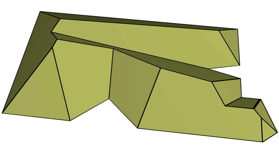
The roof model is a useful theoretical tool when dealing with straight skeletons as it makes some proofs easier. It is also directly useful as a solution for modeling terrains or actual roofs of buildings. See Figure 2 for an illustration.
Straight Skeleton with Multiplicative Weights
As a first generalization of unweighted straight skeletons, the multiplicatively-weighted straight skeleton was introduced early on by Aichholzer and Aurenhammer [2] and then by Eppstein and Erickson [3]. In the presence of multiplicative weights, wavefront edges no longer move at unit speed. Rather, they move at different speeds depending on a weight function where is the edge-set of . That is, every edge is assigned its own constant speed . The wavefront fragments of are contained in . See Figure 3 for a multiplicatively-weighted straight skeleton; the corresponding roof is shown in Figure 4.

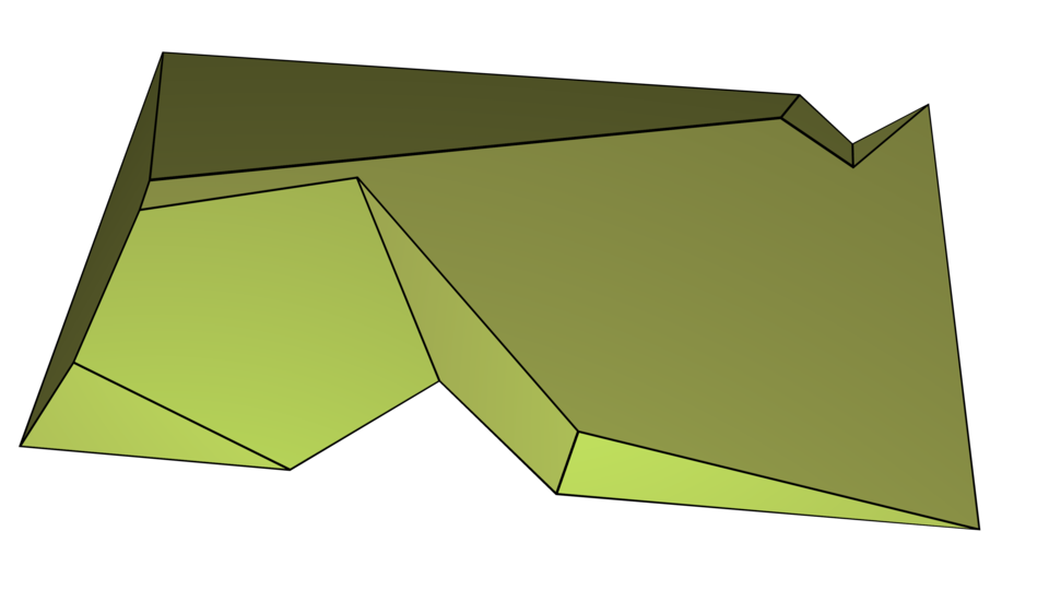
Although multiplicatively-weighted straight skeletons have been used in various applications for quite a few years — recall Section 1.1 — their characteristics were studied in full mathematical rigor only recently by Biedl et al. [4]. If all weights are required to be positive, then most of the well-known properties of straight skeletons are preserved. One prominent exception is that a face need not be monotone to its defining input edge any more; see, for example, the face traced out by the edge marked with in Figure 3. For negative weights, need not even be a tree, may contain crossings, and the roof need not be a terrain [4]. (A negative weight means that the edge moves outwards with speed .) See Figure 5 for a multiplicatively-weighted straight skeleton of a convex polygon that contains crossing arcs due to negative weights.

3 Additively-Weighted Straight Skeletons
3.1 Definition
Given a simple polygon and an additive-weight function , we define the additively-weighted wavefront as follows: As in the unweighted case, is identical to . However, wavefront edges do not all start to move immediately. Rather, an edge of the wavefront that is emanated from polygon edge will only start to move inwards at unit speed at time . Therefore, the wavefront fragments of are contained in
This can also be written as .
Since wavefront edges no longer move all at once, wavefront vertices will not travel exclusively along bisectors of input edges. If both incident wavefront edges have not yet started to move, then the wavefront vertex will obviously remain stationary. If exactly one incident wavefront edge has started to move, then the wavefront vertex will travel on the supporting line of the other; see Figure 6.


During the propagation process the wavefront will see instances of edge and split events, and it needs to be updated accordingly to restore planarity after such an event. Note that even edges and vertices that have not yet started to move can be involved in both types of events. See, for instance, the edge in the top right of Figure 8, which collapses before it starts moving. The wavefront propagation process ends when all wavefront polygons have collapsed.

For simulating the propagation process, we consider an additional event: We call the instance when an edge starts to move a speed-change event. For a wavefront edge emanated from polygon edge this will be at time . Speed-change events at time zero are called trivial, and we usually may disregard them simply by setting up the kinetic wavefront with already moving edges for time zero.
A speed-change event does not modify the combinatorial properties of the wavefront, but it does change which elements move at which speeds. In particular, when a fragment starts to move, the direction and speed of its incident wavefront vertices change.
The additively-weighted straight skeleton is then defined as the geometric graph whose edges are the traces of vertices of over its propagation period. Additionally, if two parallel wavefront edges move into each other during the wavefront propagation, then the portion common to them is also added to the straight skeleton.
As in the unweighted case, we call edges of arcs and its vertices nodes. Similarly, we again call the loci traced out by the wavefront segments of edge the face of , again given by .
3.2 Properties
Node Degrees
In unweighted or multiplicatively-weighted straight skeletons, a node will be of degree one when it is a leaf of the straight skeleton — its locus will then be at a vertex of the input polygon — or of degree three when it is the result of an elementary edge or split event. Nodes with higher degrees are also possible and are induced by non-elementary events where more than three wavefront edges are involved [19].
In addition to these types of nodes, the additively-weighted straight skeleton can have nodes of degree two. Degree-two nodes occur when a vertex of the wavefront changes its velocity due to an incident wavefront edge starting to move. Such nodes always lie on the supporting line of the input edge whose speed-change event caused it. See, for instance, the two pairs of nodes marked with for the top left edge in Figure 8 — we have two pairs rather than just one because the edge was involved in a split event earlier on.
Nested Wavefronts
The following Lemma 1 establishes that the wavefronts of additively-weighted straight skeletons are nested inside each other. Hence we get a situation similar to unweighted straight skeletons or straight skeletons with positive multiplicative weights, except that the inclusions need not be proper, since stationary edges of the wavefronts may overlap.
Lemma 1.
Let with . Then lies within , i.e., .
Proof.
Edges that are already moving at time keep moving towards the interior of , and edges that are still stationary do not move towards the outside either.
Note that a vertex of a stationary edge may move. However, if it does move, then it moves only towards the interior of the wavefront polygon or along its boundary within the interior of . It never moves towards the outside of since the other edge incident at does not move towards the outside of the wavefront polygon either. This is illustrated in Figure 6. ∎
Roof Model
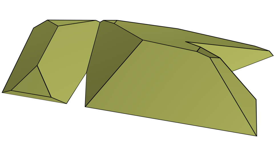
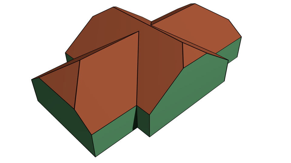
The roof induced by an additively-weighted straight skeleton is defined similarly to its unweighted pendant as . Unlike the roof induced by an unweighted straight skeleton, it is clearly no longer strictly -monotone, since wavefront edges may stay on the same supporting line during the propagation, resulting in vertical facets. The house depicted in Figure 9 has many such facets, namely the walls, as all input edges have (different) additive weights assigned to them. The weight assigned to some edges is larger, resulting in some walls continuing upwards while inclined roof facets already exist at the same height.


Lemma 2.
The roof induced by an additively-weighted straight skeleton of is weakly -monotone.
Proof.
This is a direct consequence of Lemma 1. ∎
For each edge of the polygon, the roof will have at least one facet, namely the one incident to . If the segments of see a speed-change event during the propagation process, one additional facet per segment will be visible in the roof. Note that the total number of facets is still linear in the number of vertices of the input polygon since additional wavefront segments can only be caused by split events, whose number is guaranteed to be at most linear in the number of vertices.
Crossings, Planarity, and Connectedness
Biedl et al. [4] show that the multiplicatively-weighted straight skeleton is free of crossings111Briefly, the set of crossing-free embeddings of a graph is the closure of the set of planar embeddings of with respect to the topology induced by a vertex-wise distance metric. for positive edge weights : Any locus of a crossing would have to be covered twice by the wavefront. Thus, the line parallel to through would intersect the roof twice. However, the roof is strictly -monotone, and therefore no such point can exist.
This result extends to additive weights including zero, as the projection of the weakly -monotone roof to the -plane is likewise free of crossings.
Lemma 3.
The additively-weighted straight skeleton of a simple polygon is free of crossings.
Note, however, that we cannot infer strict planarity from being free of crossings: Assume is a wavefront vertex where one incident edge has not yet started to move. Let be the other edge incident at . Then travels on the supporting line of , and the direction of this movement depends on the angle that spans with ; see Figure 6.
Now let collapse in an edge event. Let be the new neighbor of and let be the wavefront vertex common to and . At the time of the edge event, when first exists, it will be in the same locus as , the common vertex of and that it replaces in the wavefront. If the angle at previously was reflex and at it is now convex, then will move in the opposite direction of . This results in the arc being traced out by to overlap the arc already traced out by ; see Figure 10.


Note that if the angle at was convex then moved on the supporting line of within the interior of (Figure 6(b)). The area behind is outside of the wavefront polygon. There are no events the wavefront can undergo which would replace with a reflex vertex that moves in the opposite direction: such an event would cause to move outside of the wavefront polygon, violating Lemma 1. Figure 11 illustrates this fact.

Lemma 4.
Let be the portion of traced by the wavefront until time , for some . If two points are path-connected on , then they are path-connected on .
Proof.
This is shown for multiplicatively-weighted straight skeletons in Lemma 13 of [4]. We extend their proof here.
Connectivity of and is not broken despite the changes to the wavefront caused by edge and split events. Whenever an event removes elements from the wavefront, a straight-skeleton node is created to which arcs are incident that are traced out by vertices of each element involved. Likewise, after a split event, all resulting wavefront components are connected to the straight skeleton node that witnessed that event.
Therefore, it only remains to show that connectivity is maintained across speed-change events. This also holds, as such an event does not change the combinatorial properties of the wavefront. It will only result in vertices moving at different velocities. Thus, a path between points and of that goes over wavefront elements cannot be split by changes to the wavefront. ∎
Lemma 5.
The additively-weighted straight skeleton of a simple polygon is connected.
Proof.
Initially, at time zero, the straight skeleton contains only disconnected nodes. These are at the vertices of and therefore also at the wavefront vertices at time zero. The wavefront is a single polygon identical to , and so all nodes of are connected via . By Lemma 4, therefore, is connected. ∎
Faces
As for unweighted and multiplicatively-weighted straight skeletons, for each edge of we defined its face as , where is the set of segments of the wavefront at time that were emanated by . Initially, will consist of only one segment that coincides with , but as the wavefront propagates, segments may get split and segments may get dropped from when they collapse. However, at no time will a segment just jump into existence. Hence each face is connected.
Note, however, that is not necessarily a simple polygon for edges that do not immediately start to move. The faces in Figure 8 that correspond to the edges with non-zero additive weights demonstrate this fact. In clockwise order from the top left, we have a face whose interior is disconnected, a face with an empty interior because its corresponding edge collapsed before it started to move, and a face whose interior is not adjacent to itself.
Lemma 6.
A face of an additively-weighted straight skeleton is connected. Its interior may be empty or disconnected. The interior need not be adjacent to the edge which emanated the face.
In the unweighted straight skeleton, the face of an edge is a monotone polygon with respect to the supporting line of . This is, however, not always true for additively-weighted straight skeletons:
Lemma 7.
A face of an additively-weighted straight skeleton need not be monotone with respect to the edge that emanated it.
Proof.
See the topmost face in Figure 8. ∎
4 Discussion
4.1 Roof and Terrain Construction
Once the footprint of the building upon which we want to construct a roof is fixed, we have two major options to influence the shape of a straight-skeleton-induced roof.
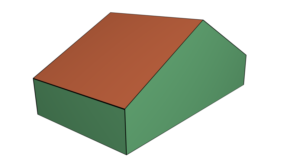
For each wall of the building we can specify at which height the roof should start to slope inwards, if at all. The additive weight that we assign to each input edge translates exactly to that height; recall Figure 9. If is sufficiently large such that during the wavefront propagation its corresponding wavefront edge collapses before that time, then the roof will not contain a corresponding sloped roof facet; see Figure 12. Note that the ridge of the roof of Figure 12 is perpendicular to the two longer walls of the house, thereby extending from one of them to the other. (This is a feature which cannot be achieved by unweighted straight skeletons.)

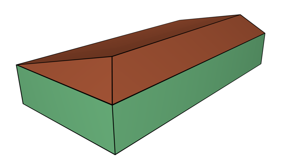
By choosing appropriate multiplicative weights for the input edges, we can influence the slopes of the facets of the roof. It is easy to see that the tangent of the angle between a roof facet and the -plane is inversely proportional to the multiplicative weight of the corresponding input edge; see Figure 13. Note that the vertical walls of that house are not induced by the multiplicatively-weighted straight skeleton. They could, however, be generated by combining both additive and multiplicative weights! (See below.)

4.2 Generalizations
Several generalizations seem natural. First, we can combine multiplicative weights with additive weights. Recall that in none of the arguments and proofs for the additively-weighted straight skeleton we had relied on the speed of all moving edges to be equal to one, or even just to be uniform. As long as all speeds are non-negative, the multiplicatively- and additively-weighted straight skeleton is well-defined and possesses the properties laid out in the previous section. Negative multiplicative weights cannot be allowed since, e.g., Lemma 1 would not hold and the straight skeleton need not even be a tree [4].
Negative additive weights, however, can be handled without much difficulty: The wavefront propagation simply starts at the time that corresponds to the smallest (negative) weight. The straight skeleton itself is invariant to the addition of a constant value to the additive weights of all edges — it just results in the wavefront propagation starting sooner or later. Hence, we could also handle negative additive weights by subtracting the smallest negative weight from all weights, thus running the wavefront propagation for only non-negative weights. In terms of the roof model, such additions merely mean shifting the whole structure along the -axis.
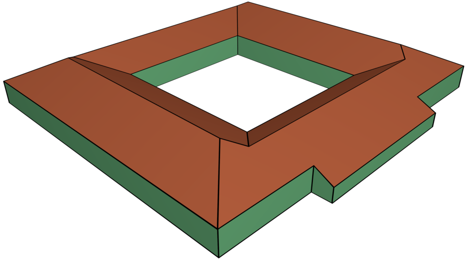
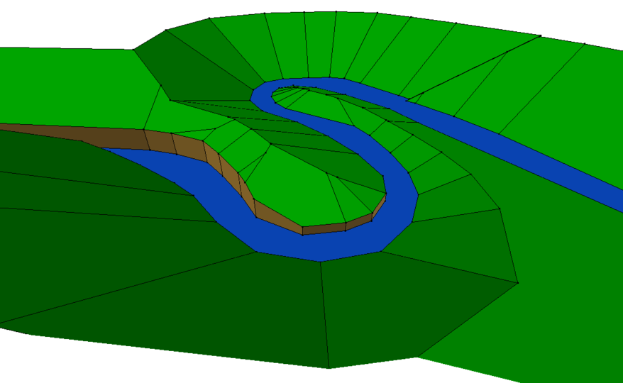
Second, as for unweighted straight skeletons, multiplicatively- and additively-weighted straight skeletons can be defined not only for simple polygons but for polygonal areas with holes or even for arbitrary planar straight-line graphs (PSLGs). Figure 14 shows a roof of a house that has an inner courtyard. Supporting PSLGs is particularly important when terrains defined by straight-line networks (rivers, roads, etc.) are to be handled. Of course, since no interior or similar sideness is implied by a PSLG, weights have to be specified for both sides of an edge of a PSLG. See Figure 16 for a sample terrain induced by an additively- and multiplicatively-weighted straight skeleton shown in Figure 16.

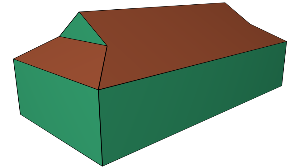
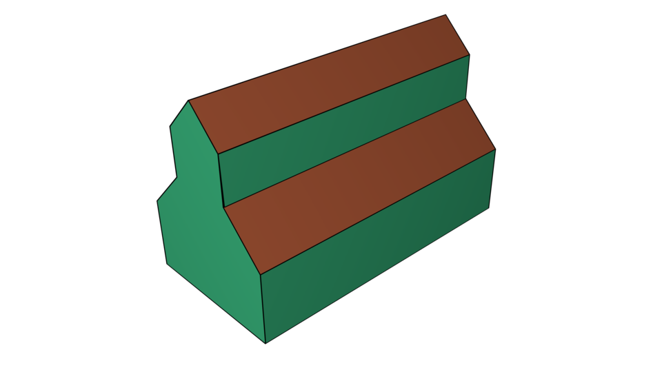
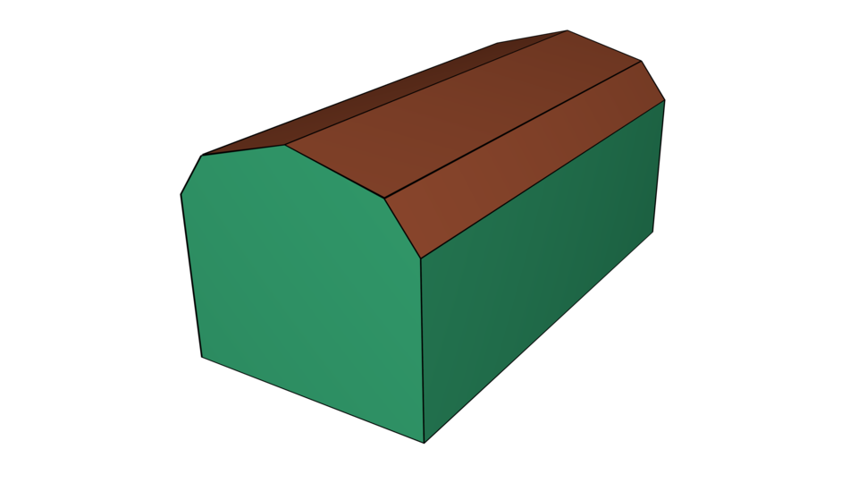
Third, one can allow more than a single speed-change per edge. As long as the speed function for an edge remains piecewise constant, vertices will still move along straight lines, all our lemmas and observations hold and, thus, the straight skeleton will exhibit the properties discussed. See Figure 17(a) for a sample gablet roof where the additive and multiplicative weights of the edges change over time. Clerestory and gambrel roofs can be generated similarly; see Figures 17(b) and 17(c).
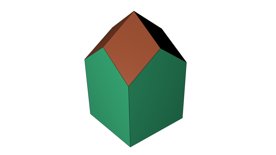
Fourth, by inserting into the input polygon infinitesimally short edges near edges with positive (or even infinite) additive weights, roof facets which are not orthogonal to any input edge of non-zero length can be created. This variant was used to create the rhombic roof from Figure 17(d).
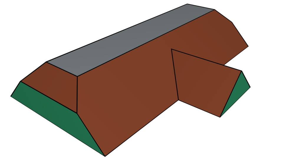
Recall that straight skeletons are defined by a wavefront propagation. Running that process until all wavefronts have collapsed will result in the full roof. We could, however, also halt the wavefront propagation at some specific point in time. This will result in roofs which have flat portions. See Figure 17(e) for a T-shaped house with a flat top. From a mathematical point of view, a flat portion of a roof corresponds to a speed change where the speed of one or more edges of the wavefront becomes infinite.
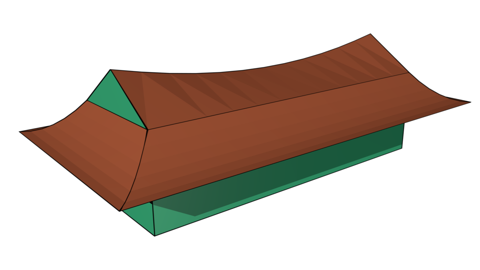
Finally, standard post-processing techniques are also applicable to roofs induced by straight skeletons. Figure 17(f) shows a modification of the gablet roof of Figure 17(a) where some ridges were replaced by curved arcs, thus making it resemble the roof of an Asian-style temple.
4.3 Computational Aspects
A simple method is described by Aichholzer et al. [1] to compute the unweighted straight skeleton: Compute the many collapse times of all edges and the many times of all potential split events, and maintain them in a priority queue. When handling an event only a constant number of edge collapses have to be recomputed, at constant cost each. Since the total number of events is linear, the overall algorithm runs in time within memory, where is the number of vertices of the input polygon.
For the additively-weighted straight skeleton, the same approach can be used. The computation of potential split event times is slightly more involved but still in . On speed-change events, a possibly linear number of collapses have to be recomputed, but the amortized cost for these is still only linear. Therefore, the additively-weighted straight skeleton can also be computed in time and space.
Biedl et al. [20] compute the multiplicatively-weighted straight skeleton (for positive weights) for monotone polygons in time and space. Their approach hinges on the fact that all mitered offsets of a monotone polygonal chain are still monotone. As this property carries over to additively-weighted input as well, the same algorithm can also be used to compute additively-weighted straight skeletons for monotone polygons in time . This promises to be useful in practice as footprints of buildings often are monotone polygons.
Aichholzer and Aurenhammer [2] describe a triangulation-based algorithm. Their core idea is to maintain a kinetic triangulation of the wavefront polygons, and to keep track of triangle collapses in a priority queue since triangle collapses signal events. As in our prior work [21], it is this algorithm that we base our implementation on. We augmented the priority queue with the times of speed-change events, and are thus able to compute additively-weighted straight skeletons.
Our implementation is based on CGAL [22] and is capable of exactly computing the straight skeleton of a PSLG with non-negative additive and multiplicative weights. The straight skeletons and offsets in the figures of this paper were produced by our code. For the images, our implementation exported the facets of the roofs and terrains to the graphics software Blender [23] for rendering.
Acknowledgements
Research by Martin Held and Peter Palfrader is supported by Austrian Science Fund (FWF): P25816-N15.
References
References
- [1] O. Aichholzer, F. Aurenhammer, D. Alberts, B. Gärtner, A Novel Type of Skeleton for Polygons, J. Univ. Comp. Sci 1 (12) (1995) 752–761. doi:10.1007/978-3-642-80350-5_65.
- [2] O. Aichholzer, F. Aurenhammer, Straight Skeletons for General Polygonal Figures in the Plane, in: Voronoi’s Impact on Modern Sciences II, Vol. 21, Institute of Mathematics of the National Academy of Sciences of Ukraine, Kiev, Ukraine, 1998, pp. 7–21. doi:10.1007/3-540-61332-3_144.
- [3] D. Eppstein, J. Erickson, Raising Roofs, Crashing Cycles, and Playing Pool: Applications of a Data Structure for Finding Pairwise Interactions, Discrete & Comp. Geom. 22 (4) (1999) 569–592. doi:10.1145/276884.276891.
- [4] T. Biedl, M. Held, S. Huber, D. Kaaser, P. Palfrader, Weighted Straight Skeletons in the Plane, Comp. Geom.: Theory and Appl. 48 (2) (2015) 120–133. doi:10.1016/j.comgeo.2014.08.006.
- [5] F. Aurenhammer, Weighted Skeletons and Fixed-Share Decomposition, Comp. Geom.: Theory and Appl. 40 (2) (2008) 93–101. doi:10.1016/j.comgeo.2007.08.002.
- [6] G. Barequet, D. Eppstein, M. T. Goodrich, A. Vaxman, Straight Skeletons of Three-Dimensional Polyhedra, in: Proc. 16th Annu. Europ. Symp. Alg. (ESA 2008), Vol. 5193 of LNCS, Springer, Karlsruhe, Germany, 2008, pp. 148–160. doi:10.1007/978-3-540-87744-8_13.
- [7] G. Barequet, E. Yakersberg, Morphing Between Shapes by Using Their Straight Skeletons, in: Proc.19thSympos. Comp. Geom., 2003, pp. 378–379. doi:http://doi.acm.org/10.1145/777792.777852.
- [8] A. Tomoeda, K. Sugihara, Computational Creation of a New Illusionary Solid Sign, in: Proc. 9th Int. Sympos. Voronoi Diagrams in Sci. & Eng. (ISVD 2012), IEEE Computer Society, Rutgers, NJ, USA, 2012, pp. 144–147. doi:10.1109/ISVD.2012.26.
- [9] K. Sugihara, Design of Pop-Up Cards Based on Weighted Straight Skeletons, in: Proc. 10th Int. Sympos. Voronoi Diagrams in Sci. & Eng. (ISVD 2013), IEEE Computer Society, St. Petersburg, Russia, 2013, pp. 23–28. doi:10.1109/ISVD.2013.9.
- [10] J.-H. Haunert, M. Sester, Area Collapse and Road Centerlines based on Straight Skeletons, GeoInformatica 12 (2) (2008) 169–191. doi:10.1007/s10707-007-0028-x.
- [11] C. Vanegas, T. Kelly, B. Weber, J. Halatsch, D. Aliaga, P. Müller, Procedural Generation of Parcels in Urban Modeling, Comput. Graph. Forum 31 (2pt3) (2012) 681–690. doi:10.1111/j.1467-8659.2012.03047.x.
- [12] M. Larive, V. Gaildrat, Wall Grammar for Building Generation, in: Proc. 4th Int. Conf. Computer Graphics and Interactive Techniques in Australasia and Southeast Asia (GRAPHITE ’06), 2006, pp. 429–437. doi:10.1145/1174429.1174501.
- [13] P. Müller, P. Wonka, S. Haegler, A. Ulmer, L. V. Gool, Procedural Modeling of Buildings, ACM Trans. Graph. 25 (3) (2006) 614–623. doi:10.1145/1141911.1141931.
- [14] C. Buron, J.-E. Marvie, P. Gautron, GPU Roof Grammars, in: Eurographics 2013 — Short Papers, 2013. doi:10.2312/conf/EG2013/short/085-088.
- [15] K. Sugihara, Straight Skeleton for Automatic Generation of 3-D Building Models with General Shaped Roofs, in: 21st Int. Conf. Comput. Graphics, Visualizat., Comput. Vision, 2013, pp. 175–183.
- [16] K. Sugihara, Automatic Generation of 3D Building Models for Sustainable Development, Int. Review Spatial Planning Sustainable Development 3 (2) (2015) 68–78.
- [17] R. G. Laycock, A. M. Day, Automatically Generating Large Urban Environments based on the Footprint Data of Buildings, in: Proc. 8th Sympos. Solid Modeling Appl. (SM 2003), Seattle, WA, USA, 2003, pp. 346–351. doi:10.1145/781606.781663.
- [18] T. Kelly, P. Wonka, Interactive Architectural Modeling with Procedural Extrusions, ACM Trans. Graph. 30 (2) (2011) 14:1–14:15. doi:10.1145/1944846.1944854.
- [19] T. Biedl, S. Huber, P. Palfrader, Planar Matchings for Weighted Straight Skeletons, in: Proc. 25th Int. Sympos. Alg. & Comp. (ISAAC 2014), Vol. 8889 of LNCS, Springer, Jeonju, Korea, 2014, pp. 117–127. doi:10.1007/978-3-319-13075-0_10.
- [20] T. Biedl, M. Held, S. Huber, D. Kaaser, P. Palfrader, A Simple Algorithm for Computing Positively Weighted Straight Skeletons of Monotone Polygons, Inform. Process. Lett. 115 (2) (2015) 243–247. doi:10.1016/j.ipl.2014.09.021.
- [21] P. Palfrader, M. Held, S. Huber, On Computing Straight Skeletons by Means of Kinetic Triangulations, in: Proc. 20th Annu. Europ. Symp. Alg. (ESA 2012), Vol. 7501 of LNCS, Springer, Ljubljana, Slovenia, 2012, pp. 766–777. doi:10.1007/978-3-642-33090-2_66.
- [22] CGAL, Computational Geometry Algorithms Library, http://www.cgal.org/.
- [23] Blender, Free and Open Source Graphics Software, https://www.blender.org/.