Development of Muon Drift-Tube Detectors for High-Luminosity Upgrades of the Large Hadron Collider
Abstract
The muon detectors of the experiments at the Large Hadron Collider (LHC) have to cope with unprecedentedly high neutron and gamma ray background rates. In the forward regions of the muon spectrometer of the ATLAS detector, for instance, counting rates of 1.7 kHz/cm2 are reached at the LHC design luminosity. For high-luminosity upgrades of the LHC, up to 10 times higher background rates are expected which require replacement of the muon chambers in the critical detector regions. Tests at the CERN Gamma Irradiation Facility showed that drift-tube detectors with 15 mm diameter aluminum tubes operated with Ar:CO2 (93:7) gas at 3 bar and a maximum drift time of about 200 ns provide efficient and high-resolution muon tracking up to the highest expected rates. For 15 mm tube diameter, space charge effects deteriorating the spatial resolution at high rates are strongly suppressed. The sense wires have to be positioned in the chamber with an accuracy of better than m in order to achieve the desired spatial resolution of a chamber of m up to the highest rates. We report about the design, construction and test of prototype detectors which fulfill these requirements.
keywords:
Drift tubes , muon chambers , LHC1 Introduction
The muon detectors of the experiments at the Large Hadron Collider (LHC) will encounter unprecedentedly high background counting rates due to neutrons and gamma rays in the energy range up to about 10 MeV which originate mainly from secondary interactions of the hadronic collision products with accelerator elements, shielding material and the detector components. The forward regions of the detectors are particulary exposed to the background radiation.
In the muon spectrometer of the ATLAS detector [1, 2] at the LHC, large Monitored Drift-Tube (MDT) chambers are used for precision tracking in a toroidal magnetic field of superconducting air-core magnets [3, 2]. The MDT chambers consist of two triple or quadruple layers of pressurized aluminum drift tubes of 30 mm outer diameter and 0.4 mm wall thickness, filled with an Ar:CO2 (93:7) gas mixture at an absolute pressure of 3 bar. An operating voltage of 3080 V, corresponding to a gas gain of , is applied between the tube wall and the 50 m diameter anode wire. The gas mixture and gas gain have been chosen to prevent aging of the drift tubes up to an accumulated charge of at least 0.6 C/cm in the high background environment at the LHC. The average spatial resolution of individual drift tubes at low background rates of 80 m together with the positioning accuracy of the sense wires in a chamber of m translates into a spatial resolution of a MDT chamber of 35 m.
The highest background rate in the ATLAS MDT chambers at the LHC design luminosity of 1034cm2s-1 is expected to be 100 Hz/cm2 in the inner endcap layers closest to the beam pipe [4]. The limited knowledge of the showering process in the absorber, chamber sensitivities and cross section and particle multiplicity of the primary proton collisions at the LHC center-of-mass energy of TeV is taken into account in a safety factor of 5. Hence the MDT chambers are designed to cope with particle fluxes of up to 500 Hz/cm2 corresponding to a maximum counting rate of 300 kHz in 2 m long drift tubes of the inner forward chambers.
The LHC upgrade schedule foresees a continuous luminosity increase up to three times the design luminosity and followed eventually by a larger upgrade to ten times the design luminosity called Super-LHC (S-LHC). Assuming that the background rates will scale with the luminosity, the degradation of the performance of the MDT chambers will compromise the ATLAS physics goals. We investigate the possibility of using drift-tube detectors with smaller tube diameter and therefore shorter drift-time for the regions of highest background rates in the muon detectors of the LHC experiments. Building on the experience with the ATLAS MDT chambers, new muon drift-tube detectors with 15 mm diameter tubes for counting rates up to about 1.5 kHz/cm2 have been developed and tested.
2 Drift-tube performance at high rates
At high counting rates, the drift tubes of the MDT chambers are known to suffer from a degradation of the spatial resolution due to space-charge effects [5, 6] and of the muon detection efficiency due to the increased drift tube occupancy [7]. Both effects can be supressed by reducing the tube diameter while leaving the other parameters of the drift tubes, in particular the gas mixture and pressure and the gas gain, unchanged.
A smaller outer tube diameter of 15 mm instead of 30 mm leads to a reduction of the maximum drift time by a factor of 3.5 from about 700 ns to 200 ns (see Fig. 1) when the operating voltage is reduced from 3080 V to 2730 V to keep the gas gain the same. In addition, the background counting rate, dominated by the conversion of the neutron and gamma radiation in the tube walls, is reduced by a factor of two per unit tube length proportional to the tube circumference. Neglecting electronics shaping and dead time, which should be minimized, both effects lead to a reduction of the drift-tube occupancy by about a factor of 7. The occupancy of 15 mm diameter drift tubes stays below up to the highest counting rate of 1500 kHz expected in 2 m long tubes in the ATLAS inner forward chambers at S-LHC. A first verification of the expected increase of the detection efficiency of 15 mm diameter compared to 30 mm diameter drift tubes at high counting rates has been obtained up to rates of about 300 kHz per tube at a recent test with cosmic rays at the CERN Gamma Irradiation Facility GIF [8].
The space-charge distribution generated by the ion clouds drifting towards the tube wall changes the electric field, influencing both the drift velocity and the gas gain. By lowering the effective potential experienced by the electrons drifting to the wire, high counting rates lead to decreasing gas gain. The resulting signal loss grows with the inner tube radius proportional to [9], where m is the wire radius, and is therefore 10 times smaller in 15 mm compared to 30 mm diameter tubes. Fluctuations of the space charge and of the electric field lead to variations of the drift velocity causing a deterioration of the spatial resolution in non-linear drift gases like Ar:CO2 (93:7) where the drift velocity depends on the electric field. The latter effect increases strongly with drift distance above a value of about 7.5 mm while the gain drop effect on the spatial resolution dominates for distances close to the sense wire. For drift radii below 7.5 mm the space-to-drift time relationship is more linear leading to a reduced sensitivity to environmental parameters such as gas composition and density, magnetic field and irradiation rate.
Since the spatial resolution of the drift tubes increases with the drift radius, the average single-tube resolution deteriorates from m for 30 mm diameter tubes [6, 7] to about m for 15 mm diameter tubes at low rates. The rate dependence of the 30 mm diameter drift-tube resolution has been measured previously [6, 7] in a muon beam at the CERN GIF facility. The resolution deteriorates linearly with the counting rate to about m at 500 Hz/cm2. For 15 mm diameter tubes, the rate dependence of the resolution, dominated by the gain drop effect, is predicted to be more than 10 times smaller causing a degradation of the resolution by only m at the maximum counting rate of 5000 Hz/cm2 expected at S-LHC.
3 Chamber design and fabrication
The design of new drift-tube chambers with 15 mm diameter tubes follows as much as possible the current ATLAS MDT chamber design. In order to use the new chambers for an upgrade of the endcap region of the ATLAS muon spectrometer, they have to fit into the same volume as the current chambers. This allows for at least twice the number of drift-tube layers compared to the existing chambers with 30 mm diameter tubes and a corresponding improvement of the track segment reconstruction efficiency and spatial resolution. The baseline design of new inner forward chambers thus comprises two times eight tube layers compared to the two times four layers of the present inner forward MDT chambers. The spatial resolution of these chambers is expected to be better than m up to a counting rate of 5 kHz/cm2 with a sense wire positioning accuracy in the chambers of m which is a less stringent requirement then for the current MDT chambers.
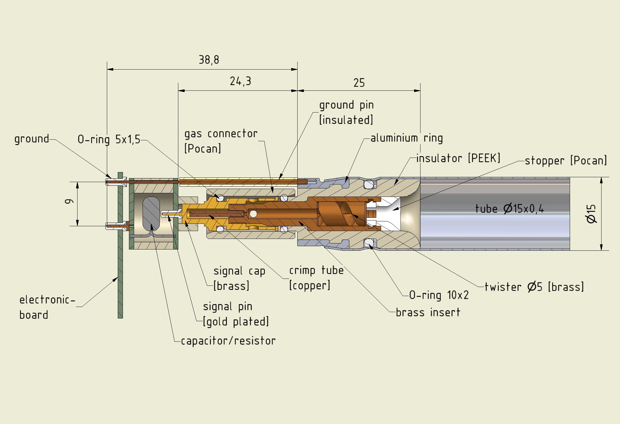
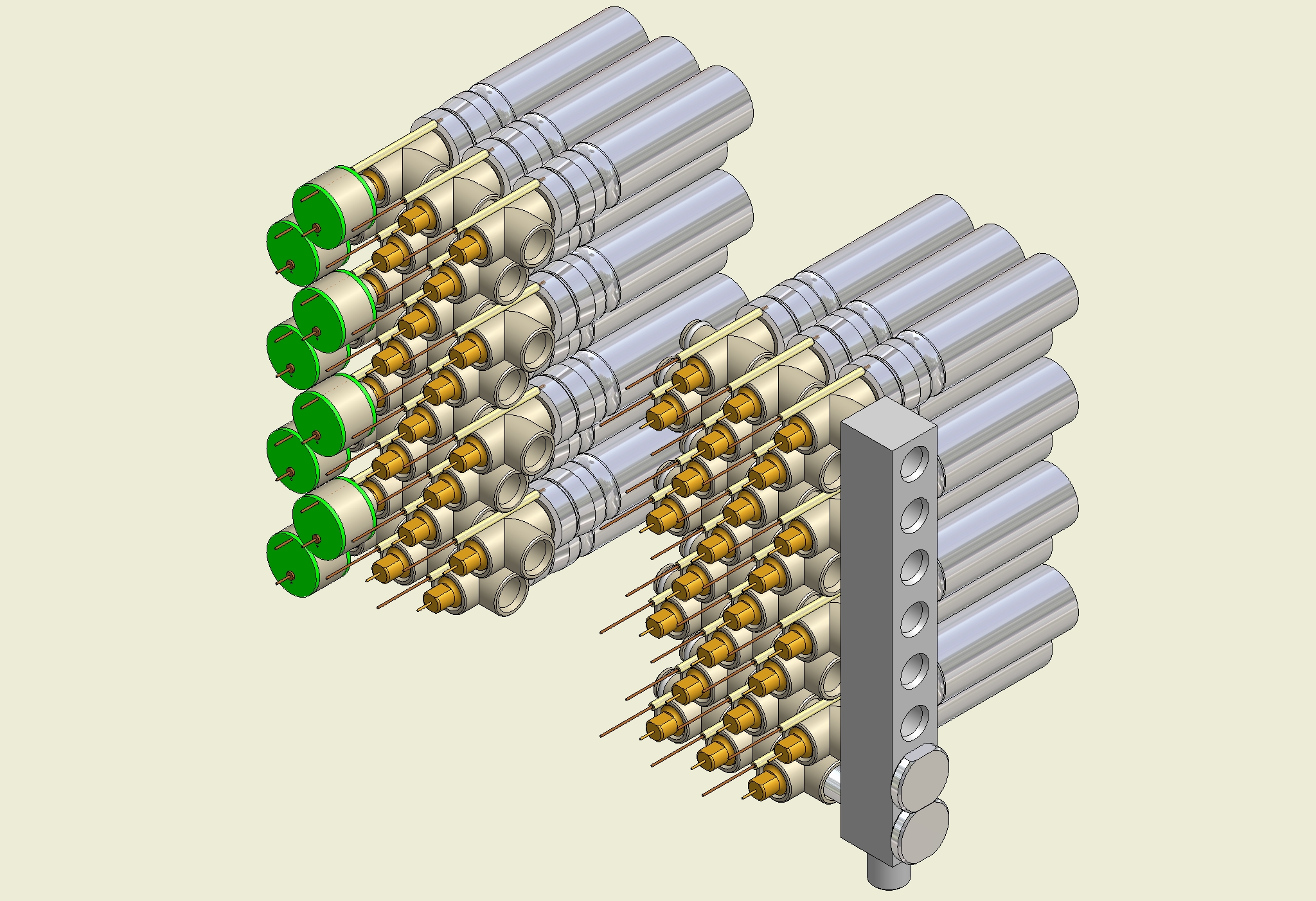
The challenge for the new chamber design is the four times denser tube package with corresponding gas and electrical connections to the individual tubes. Central to the chamber design is the development of the tube endplug (see Fig. 2) which insulates the sense wire from the tube wall, centers the wire in the tubes with respect to an external reference surface on the endplug with an accuracy of about m and provides high-voltage-safe connections to the gas distribution manifolds (see Fig. 3) and the readout and high-voltage distribution boards. Gas leak rates have to stay below barl/s per tube in order to prevent contamination of the drift gas. The wire is fixed at both tube ends in copper crimping tubes inserted into the central brass inserts of the endplugs and connected to the signal and high-voltage distribution boards via brass signal caps screwed onto the brass inserts and sealing the tubes with the gas manifolds at both ends with rubber O-rings. The brass insert holds the spiral-shaped wire locator (called twister) on the inside of the tube and transfers its position in the plane perpendicular to the wire to a precisely machined reference surface on the outside of the tube which is used for the accurate relative positioning of the drift tubes in the chamber during chamber assembly. The endplugs are fabricated by injection molding and sealed in the tubes with O-rings by circular crimping of the tube walls. Injection moulded adapter pieces, containing the high-voltage decoupling capacitor, connect the signal caps to the readout and high-voltage distribution boards at the two tube ends which become feasible in this design.
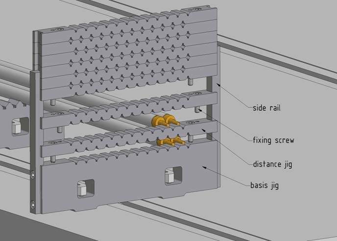
The tubes are assembled to a chamber using the precision jigging tool shown in Fig. 4. The comb-shaped device is machined with an accuracy of about m and positions the reference surfaces of the tubes of a multilayer in the plane transverse to the wires. The eight tube layers of one multilayer are assembled and glued together in a single step requiring only one working day. A module of 12x8 drift tubes has been assembled with this procedure. The external reference surfaces of the endplugs have been measured on a coordinate measuring machine after the glueing yielding the required accuracy of m rms. This has been achieved with 1 m long DIN standard aluminum tubes with tolerances of mm on diameter, roundness and concentricity of inner and outer circumference and of mm on straightness. After the assembly of the drift tubes, gas manifolds, signal caps and electronics boards are mounted. The whole chamber is finally enclosed in an aluminum faraday cage.


4 Conclusions
Drift tube detectors provide robust and efficient tracking at high occupancies expected in the muon detectors of the LHC experiments, in particular in the ATLAS detector. Drift tubes with 15 mm diameter are sufficiently fast to cope with the counting rates expected in the forward regions of the ATLAS muon spectrometer under the worst background conditions at LHC with ten times increased design luminosity (Super-LHC). The design of muon chambers with 15 mm diameter drift tubes is in an advanced stage. The construction of a first prototype chamber is under preparation.
References
- [1] The ATLAS collaboration, ATLAS Technical Proposal, CERN/LHCC 94-43, December 1994.
- [2] The ATLAS collaboration, The ATLAS Experiment at the CERN LHC, JINST 3 S080003 (2008).
- [3] The ATLAS collaboration, Technical Design Report for the ATLAS Muon Spectrometer, CERN/LHCC 97-22, May 1997.
- [4] S. Baranov et al., Estimation of Radiation Background, Impact on Detectors, Activation and Shielding Optimization in ATLAS, ATLAS internal note, ATL-GEN-2005-001 (2005).
- [5] M. Aleksa et al., Rate Effects in High-Resolution Drift Chambers, Nucl. Instr. and Meth. A 446 (2000) 435-443.
- [6] M. Deile et al., Performance of the ATLAS Precision Muon Chambers under LHC Operating Conditions, Nucl. Instr. and Meth. A518 (2004) 65-68.
- [7] S. Horvat et al., Operation of the ATLAS Precision Muon Drift-Tube Chambers at High Background Rates and in Magnetic Fields, IEEE trans. on Nucl. Science Instr. Vol. 53, 2 (2006) 562-566.
- [8] J. Dubbert et al., Precision Drift Tube Chambers for the ATLAS Muon Spectrometer at Super-LHC, proceedings of the 2008 IEEE Nuclear Science Symposium, Dresden, Germany, 19-25 October 2008, Nuclear Science Symposium Conference Record 2008, IEEE, 2008, MPI report, MPP-2008-191, November 2008.
- [9] W. Riegler, High Accuracy Wire Chambers, Nucl. Instr. and Meth. A494 (2002) 173-178.
- [10] R. Veenhof, GARFIELD: Simulation of Gaseous Detectors, Version 8.01, CERN, write-up: http://wwwinfo.cern.ch/writeup/garfield.