Three-dimensional simulations of super-critical black hole accretion disks — luminosities, photon trapping and variability.
Abstract
We present a set of four three-dimensional, general relativistic, radiation MHD simulations of black hole accretion at super-critical mass accretion rates, . We use these simulations to study how disk properties are modified when we vary the black hole mass, the black hole spin, or the mass accretion rate. In the case of a non-rotating black hole, we find that the total efficiency is of order , approximately a factor of two less than the efficiency of a standard thin accretion disk. The radiation flux in the funnel along the axis is highly super-Eddington, but only a small fraction of the energy released by accretion escapes in this region. The bulk of the of energy emerges farther out in the disk, either in the form of photospheric emission or as a wind. In the case of a black hole with a spin parameter of 0.7, we find a larger efficiency of about . By comparing the relative importance of advective and diffusive radiation transport, we show that photon trapping is effective near the equatorial plane. However, near the disk surface, vertical transport of radiation by diffusion dominates. We compare the properties of our fiducial three-dimensional run with those of an equivalent two-dimensional axisymmetric model with a mean-field dynamo. The latter simulation runs nearly 100 times faster than the three-dimensional simulation, and gives very similar results for time-averaged properties of the accretion flow.
keywords:
accretion, accretion discs – black hole physics – relativistic processes – methods: numerical1 Introduction
Black hole (BH) accretion disks are common in the Universe. It appears that virtually every galaxy harbours a supermassive black hole (SMBH) in its nucleus and it is likely that every one of these SMBHs has some kind of an accretion flow. Moreover, just in our own Galaxy, there are probably thousands of stellar-mass BHs in binaries accreting gas from their companions, of which a few dozen have been detected in X-rays and are widely studied.
Because of the compactness of BHs, accreting gas can liberate significant amounts of gravitational energy and make the accreting systems extraordinary luminous. Moreover, magnetic fields near the BH encourage the extraction of rotational energy of spinning BHs, leading to formation of powerful relativistic jets.
Early theoretical work on accretion disks was limited to one-dimensional analytical models. Later, 1+1 and two-dimensional models with -viscosity were developed. Because accretion flows are by nature turbulent, such simplified models were not adequate in most cases. Moreover, they often made strong assumptions, e.g., no mass loss, constant , zero-torque at the innermost stable circular orbit (ISCO), which may not be satisfied in real systems. This motivated the development of techniques for numerically modeling multi-dimensional turbulent accretion flows.
The key breakthroughs were the identification of the magnetorotational instability (MRI, Balbus & Hawley, 1991) and the development of magnetohydrodynamical (MHD) numerical codes, both Newtonian and relativistic. Initial efforts were focused on simulating optically thin disks, as are likely to be present at the lowest accretion rates. Such systems are relatively simple to simulate because the radiation is weak and is, moreover, decoupled from the gas. Only in recent years have more advanced radiation-MHD (RMHD) codes been developed which can be used to study radiatively luminous systems. The pioneering initial work was based on Newtonian codes with crude (flux-limited diffusion) radiative transport (Ohsuga et al., 2009; Ohsuga & Mineshige, 2011). This was later followed by codes using more advanced radiative transport schemes, either still in the Newtonian or special-relativistic approximation (Jiang et al., 2012, 2014a; Ohsuga & Takahashi, 2015), or in general relativity (Sądowski et al., 2013; McKinney et al., 2014; Fragile et al., 2014).
So far global simulations of optically thick disks that evolve the radiation field in parallel to gas have been performed only for super-critical (exceeding the Eddington value, see equation 6) accretion rates 111A number of groups (e.g., Shafee et al., 2008a; Schnittman et al., 2013; Avara et al., 2015) have performed simulations of thin disks in pure hydrodynamical setup implementing arbitrary cooling function.. Such disks are geometrically thick and do not require excessive resolution near the equatorial plane which, so far, makes self-consistent simulations of thinner disks too expensive.
In this paper we continue the numerical study of super-critical BH accretion flows by performing a set of four three-dimensional simulations, the parameters of which probe different accretion rates, BH spins, and BH masses. Such a comparative study using a single code (and set of assumptions) has not yet been performed. In addition, we compare the properties of our fiducial three-dimensional model with an equivalent axisymmetrical two-dimensional run which is simulated using the mean-field dynamo model described in Sądowski et al. (2015a).
We begin with a description of the numerical methods (Section 2) and details of the five simulations (Section 3). We then discuss the results, focusing on the luminosities of the simulated disks (Section 4), the efficiency of photon trapping (Section 5), and the variability of the emitted radiation (Section 6). Finally, we assess the strengths and weaknesses of 2D simulations (Section 7), and list the conclusions in the Summary (Section 8).
2 Numerical methods
The simulations described in this paper were performed with the general relativistic radiation magnetohydrodynamical (GRRMHD) code KORAL (Sądowski et al., 2013) which solves the conservation equations in a fixed, arbitrary spacetime using finite-difference methods. The equations we solve are,
| (1) | |||||
| (2) | |||||
| (3) |
where is the gas density in the comoving fluid frame, are the components of the gas four-velocity as measured in the “lab frame”, is the MHD stress-energy tensor in this frame,
| (4) |
is the stress-energy tensor of radiation, and is the radiative four-force describing the interaction between gas and radiation (see Sądowski et al., 2014, for a more detailed description). Here, and represent the internal energy and pressure of the gas in the comoving frame and is the magnetic field 4-vector (Gammie et al., 2003). The magnetic pressure is in geometrical units.
The magnetic field is evolved via the induction equation,
| (5) |
where is the magnetic field three-vector (Komissarov, 1999), and is the metric determinant. The divergence-free criterion is enforced using the flux-constrained scheme of Tóth (2000).
The radiation field is evolved through its energy density and flux, and the radiation stress-energy tensor is closed by means of the M1 closure scheme (Levermore, 1984; Sądowski et al., 2013). The energy exchange between gas and radiation is by free-free emission/absorption as well as Compton scattering. The latter is treated in the “blackbody” Comptonization approximation as described in Sądowski & Narayan (2015c).
Four of the five simulations described here were performed in three dimensions (3D), while the fifth was carried out in 2D, assuming axisymmetry and using the mean-field dynamo model described in Sądowski et al. (2015a) with model parameters identical to those used there.
We use modified Kerr-Shild coordinates with the inner edge of the domain inside the BH horizon. The simulations were run with a moderately high resolution of 252 grid cells spaced logarithmically in radius, 234 grid cells in the polar angle, concentrated towards the equatorial plane, and 128 cells in azimuth.
All details of the numerical method are given in Sądowski et al. (2014).
3 Simulations
3.1 Units
We adopt the following definition for the Eddington mass accretion rate,
| (6) |
where is the Eddington luminosity, is the radiative efficiency of a thin disk around a black hole with a given spin ,
| (7) |
and is the radius of the Innermost Stable Circular Orbit (ISCO). According to this definition, a standard thin, radiatively efficient disk (Shakura & Sunyaev, 1973; Novikov & Thorne, 1973; Frank et al., 1985) accreting at would have a luminosity of . For zero BH spin, .
Hereafter, we use the gravitational radius as the unit of length, and as the unit of time.
3.2 Initial setup
Each of the five simulations was initialized as in Sądowski et al. (2014), viz., by starting with the hydrodynamical equilibrium torus of Penna et al. (2013a) with the angular momentum parameters listed in Table 1, and then redistributing the pressure between gas and radiation such that local thermal equilibrium is established with the total pressure unchanged. The resulting, radiation-pressure supported torus is close to equilibrium. The initial density was set through the torus entropy parameter and was adjusted to provide an optically thick torus that would give super-critical accretion once the simulation has reached steady state.
The initial torii were threaded by weak poloidal magnetic field. As each simulation proceeded, the field grew in strength and led to the onset of the magnetorotational instability, which triggered and maintained MHD turbulence in the disk. For most models we started with multiple loops with alternating polarity. For one model (r011) we used a single loop. Both field configurations were initialized as in Sądowski et al. (2015a).
We performed two simulations with BH mass and zero BH spin. One of these (run r001) resulted in a mean accretion rate of , while the other (r003), which was initialized with a more optically thick torus, accreted at . These two models allowed us to study the role of the mass accretion rate on disk properties.
The third model (r011) was initialized with a torus similar to model r001, but we assumed a rotating BH with spin parameter . This model was the only one of the five that was initialized with a single poloidal loop of magnetic field. The hope was that the single loop would lead to a strong magnetic field at the horizon and would give a magnetically arrested disk (Igumenshchev et al., 2003; Narayan et al., 2003; Tchekhovskoy et al., 2011; McKinney et al., 2012). However, although this simulation was run up to a time of nearly 15,000, this duration was still insufficient to reach the MAD limit. Therefore, the magnetic field at the BH still did not reach the saturated level appropriate to the MAD state. Nevertheless, by comparing this model with r001, we were able to study the effect of BH spin222In a recent paper, McKinney et al. (2015) present true MAD simulations in the radiative super-critical regime. Those represent a different class of accretion flows than the ones considered here..
In the fourth model (r020), we increased the BH mass to BH, but kept the mass accretion rate at . This enabled us to investigate the role of BH mass.
All of the above models were run in 3D. The fifth model (d300) was a 2D axisymmetric simulation which used the mean-field dynamo model of Sądowski et al. (2015a). This model was initialized with exactly the same torus configuration as in model r001. The only difference was that it was evolved in 2D instead of 3D. The purpose of this model was to assess how well the 2D dynamo model captures the properties of the 3D model.
| r001 | r003 | r011 | r020 | d300 (2D) | |
| 10.0 | 175.8 | 9.7 | 10.1 | 8.9 | |
| 0.0 | 0.0 | 0.7 | 0.0 | 0.0 | |
| 10.0 | 10.0 | 10.0 | 10.0 | 10.0 | |
| initial loops | multi. | multi. | poloidal | multi. | multi. |
| x x | 252 x 234 x 128 | 252 x 234 x 128 | 252 x 234 x 128 | 252 x 234 x 128 | 252 x 234 x 1 |
| / / / | 1.85 / 1000 / 0 / 0.6 | 1.85 / 1000 / 0 / 0.6 | 1.85 / 1000 / 0 / 0.6 | 1.85 / 1000 / 0 / 0.6 | 1.85 / 1000 / 0 / 0.6 |
| / / / | 0.705 / 40 / 1000 / 22.5 | 0.705 / 40 / 1000 / 22.5 | 0.705 / 40 / 1000 / 10 | 0.705 / 40 / 1000 / 22.5 | 0.705 / 40 / 1000 / 22.5 |
| 20,000 | 19,000 | 16,100 | 19,200 | 190,000 | |
| - average accretion rate | |||||
| - maximal density of the initial torus in | |||||
| - maximal value of initial total to magnetic pressure ratio | |||||
| x x - resolution | |||||
| / / / - grid parameters defined in Sądowski et al. (2015a) | |||||
| / / / - parameters of the initial torus as defined in Penna et al. (2013a) | |||||
| - duration of simulation in units of | |||||
3.3 Accretion flow properties
Each of the four 3D simulations was run up to a final time , by which time all had developed quasi-steady, turbulent accretion via optically and geometrically thick disks. The time histories of the mass accretion rate through the BH horizon are shown in Fig. 1. In all the runs, gas starts crossing the BH horizon at a substantial rate only after . This is the time needed for the magnetorotational instability to make the disk turbulent, and for gas from the inner edge of the initial torus to accrete on the BH. Once accretion begins, the mass accretion rate increases rapidly. In fact, overshoots and remains somewhat enhanced until time , and only beyond this time does the accretion rate settle down to a quasi-steady value. In the following, we focus on disk properties averaged over the latter quasi-steady stage of accretion, from to .
The radial profile of the mass accretion rate is given by
| (8) |
Fig. 2 shows the time-averaged profiles of this quantity as a function of radius corresponding to the four 3D runs. The flat sections of the profiles at relatively small radii denote the region where the flow has reached inflow equilibrium. Given the somewhat limited duration of the simulations, and the relatively low radial velocity of the accreting gas in the disk, inflow equilibrium is reached only up to a radius . The outflows in the jet and wind regions have larger velocities, and therefore the outflowing regions are causally connected with the equatorial disk out to much larger distances from the BH. In particular, the funnel region, which is filled in most cases with gas escaping at , achieves equilibrium all the way out to the domain boundary at .
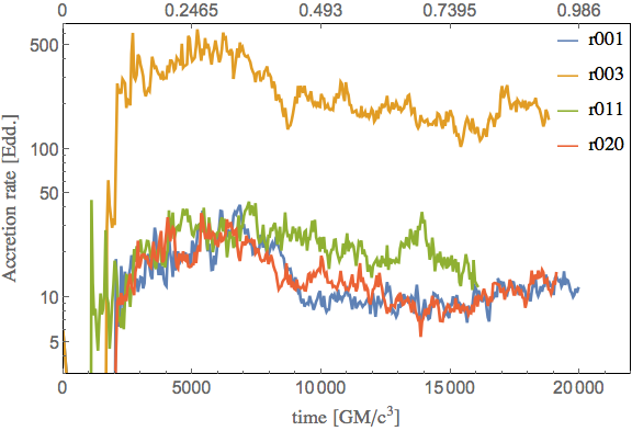

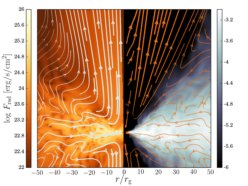
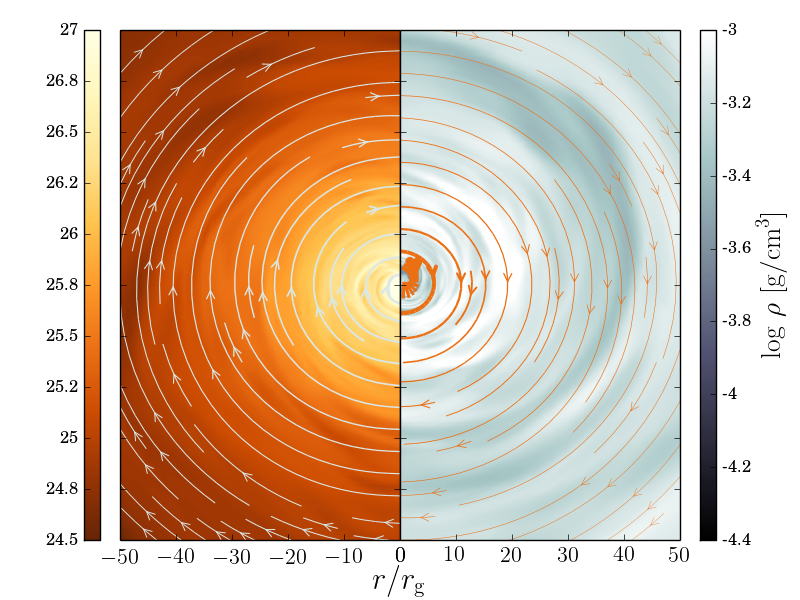
Figure 3 shows poloidal and azimuthal slices through model r001 at time . The colors in the left halves of the panels show the magnitude of the radiation field, while those in the right halves show the gas density. The arrows in the two halves show the direction of the radiative flux and gas velocity, respectively, with the arrow thicknesses indicating the corresponding magnitudes. For clarity, the vector fields were computed from time-averaged output.
The gas is concentrated near the equatorial plane and forms a geometrically thick (or slim) disk with density scale-height . Non-axisymmetric modes are clearly visible in the right panel, showing the value of running the simulations in 3D. Because of the large density, the gas is optically thick and advects with it a significant amount of radiation. This explains why the radiation flux has its largest magnitude in the bulk of the disk.
The gas in the disk region around the mid-plane is turbulent. On average the gas moves there slowly towards the BH. Outside the bulk of the disk, within deg from the pole, the gas flows outward, being driven mostly by the radiation pressure force exerted by the radial radiative flux333For a comprehensive study of the acceleration mechanism of outflows in hydrodynamical and radiative disks see Möller & Sądowski (2015)..
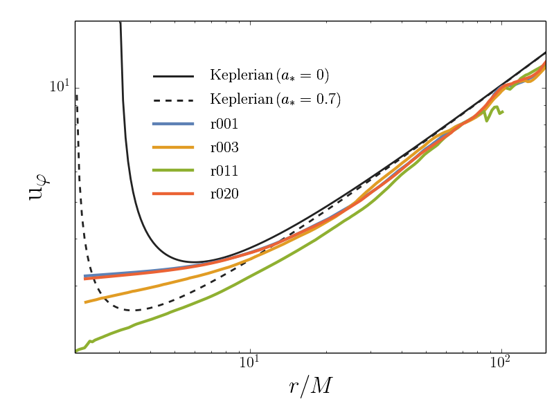
Gas in the disk region orbits around the BH but because the disk is geometrically thick the rotation is mildly sub-Keplerian, as shown by Fig. 4. Outside the ISCO, the deviation from the Keplerian profile is no more than 13% in any of the models. The angular momentum profile flattens towards the BH horizon, reflecting the fact that the effective visosity, which transports angular momentum, is less effective in the plunging region. The profile is flattest for the models with the lowest accretion rate. Extrapolating to sub-Eddington accretion rates, we thus expect the viscous torques to become insignificant for thin disks, in agreement with previous work Paczyński (2000); Afshordi & Paczyński (2003); Shafee et al. (2008a, b); Penna et al. (2010).
poloidal plane equatorial plane
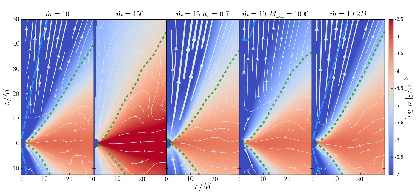
The top set of panels in Fig. 6 shows the time- and azimuth-averaged distribution of density for all the five simulations. Streamlines reflect the velocity field of the gas, with the thickness of lines denoting the density-weighted average velocity. For all the simulations the accretion flow is geometrically thick with density peaking at the equatorial plane. The density values are similar in all the runs except the simulation with the highest accretion rate, r003, which has a significantly higher density of gas (and increased optical depth). In all cases the gas flows on average towards the BH deep in the disk. The velocity of gas in the funnel is pointing outward outside the stagnation radius separating the polar region of inflowing gas (which is the boundary condition imposed by the presence of BH horizon) and the outflowing gas, driven either by radiation pressure or pressure gradients. In the case of simulations with non-rotating BHs and moderate accretion rates (three-dimensional models r001 and r020), the stagnation radius at the axis is located near . For the run with much higher accretion rate (r003) it shifts significantly outward to due to the much larger opacity, which prevents radiation from ejecting gas from the innermost region. On the other hand, the stagnation radius is very close to the BH horizon for the simulation with a rotating BH. In this model, gas is accelerated outward by an additional energy source, viz., the spin energy of the BH. The transition between the region of inflow (inside the disk), and outflow (in the funnel) is quite rapid — when gas particles are blown out of the disk and enter the funnel they quickly gain large outward radial velocity and join the outflow.
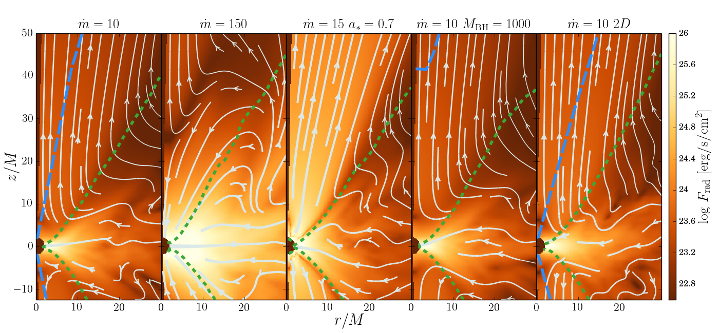
The bottom set of panels in Fig. 6 shows the averaged radiative flux for the five simulations. The colors denote the magnitude and arrows show the direction of the radiative flux. The radiation emitted by hot gas in the disk is mostly advected with the optically thick gas, but in regions close to the disk surface it also diffuses down the local density gradient (Jiang et al., 2014b). As a result, some fraction of the radiation is advected into the BH and the rest naturally fills up the funnel region. There, radiation pressure accelerates gas outward along the axis of the funnel, resulting in a jet that travels at a modest fraction (0.2–0.5) of the speed of light (Sądowski & Narayan, 2015b). The properties of the radiation field depend on the accretion rate and BH spin. For model r003, which has the largest accretion rate, a significantly higher fraction of all the radiative flux in the inner region is advected into the BH, even in the inner part of the funnel region. In simulation r011, the rotational energy of the BH is extracted (although not very efficiently due to the sub-MAD level of magnetic flux accumulated at the horizon) through the Blandford-Znajek process. This extra energy is converted into radiation and therefore this model has the highest radiative flux magnitude in the funnel region among all the runs.
The qualitative properties of the 3D simulations described here agree well with accretion flows simulated in the recent years in axisymmetry e.g., by Sądowski et al. (2014), and in three-dimensions by McKinney et al. (2014). We comment on the differences between our models and the simulation presented by Jiang et al. (2014b) in Section 8.1. Below we discuss in detail three aspects of our models – luminosities, efficiency of photon trapping, and variability.
4 Luminosities
Accretion takes place if there is an efficient mechanism for transporting angular momentum outward. In BH accretion disks, we believe that this transport results from turbulence sustained by magnetorotational-unstable magnetic field. The angular momentum flux is accompanied by fluxes of energy in various forms. In the standard picture of a thin disk, the accreting gas brings in kinetic (orbital and turbulent), thermal, and binding energy. The latter has a negative sign, so effectively the flux of binding energy transports energy out (and deposits it at infinity). The exchange of angular momentum would not be possible without a shear stress (“viscosity”) which again causes an outward flux of energy. For turbulent magnetic disks, this energy flux comes from the work done by magnetic fields. In addition, there is radiation flux. In a thin disk, radiation carries energy out to infinity. However, in geometrically thick super-Eddington accretion flows, the radiation energy flux can be either outward or inward, depending on how effectively the radiation is trapped in the optically thick flow. In addition, these models can also have mechanical energy flowing out in a wind or jet.
We postpone a comprehensive discussion of the energetics in multi-dimensional accretion disk to a forthcoming paper. Below, we limit ourselves to simple angle-integrated luminosities of the simulated disks.
4.1 Total luminosities
The most fundamental definition of the luminosity is,
| (9) |
which is the total rate of energy flowing through a sphere at some radius at some instant of time. This quantity accounts for all forms of energy except the rest-mass energy (which has been subtracted out via the term ). In particular, includes binding (gravitational), radiative, kinetic, thermal and magnetic energies. In an equilibrium steady state accretion disk, the the time-averaged luminosity is conserved, i.e., it has the same value at all radii. This is because of energy conservation: any energy that appears in one form must ultimately come from one of the other forms discussed above, and therefore the sum of all forms of energy remains constant.
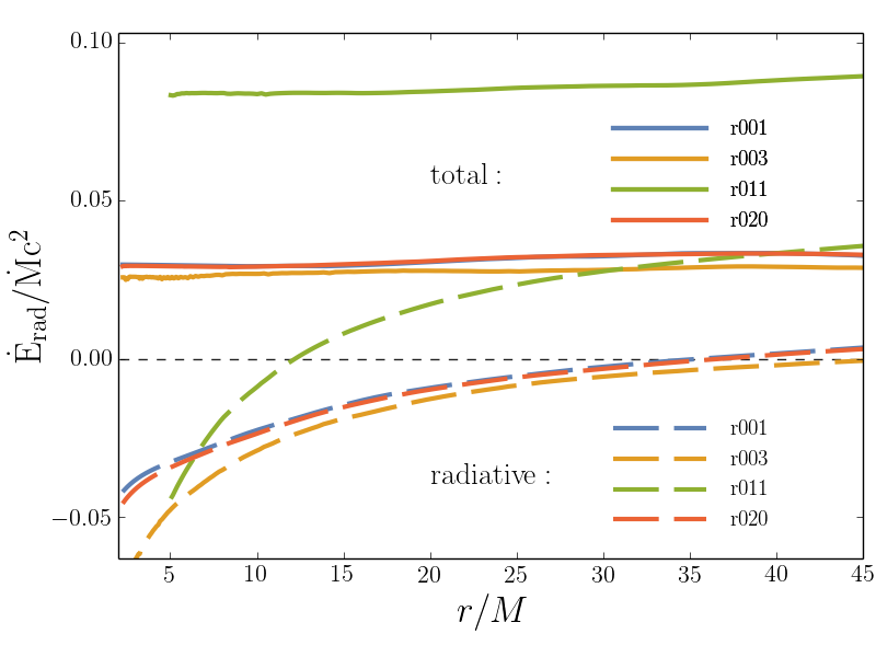
The radial profile of total luminosity is plotted with solid lines in Fig. 5. We see that it is indeed constant to good accuracy for all the runs. All the simulations with non-rotating BHs have total luminosity close to . For an accretion rate of this corresponds to (for the adopted definition of see equation 6). The luminosity is significantly higher for the simulation (r011) with a rotating BH. There are two reasons for this: (i) the disk around a spinning BH extends deeper into the potential well since the ISCO is at a smaller radius (correspondingly, the thin disk efficiency for is ), and (ii) the accumulated magnetic flux at the BH horizon allows for the extraction of BH kinetic energy through the Blandford-Znajek process. The predicted rate of that process (for the measured average magnetic flux parameter and ) is . The total energy available is therefore . In actuality, is extracted, which is roughly of the total available. A similar 50% energy extraction is seen also in the case of non-rotating BHs: a thin disk around a non-spinning BH has an efficiency of 5.7% whereas, as mentioned above, the luminosity of our models is only 3%. Total luminosities for all the simulations are given in Eddington units in the third row of Table 2.
The total luminosity as defined above may be, in principle, sensitive to the initial conditions. In the ideal world, one would initiate a simulation by dumping marginally bound (zero Bernoulli number) gas from infinity. Because the duration of real simulations is limited, we have to start our simulatons from a bound torus located close to the BH with its inner edge at . The Bernoulli number, defined as
| (10) |
of the initial gas at the very inner edge is and approaches zero inversely proportional to radius. Thus, in principle, the luminosity estimates given above may be overestimated by up to (it cannot be more, but it may be less if there is significant radial mixing of gas in the initial torus). To estimate how strongly the initial affects results we compared the total luminosities averaged over and . At , the BH had accreted an amount of gas equivalent to that contained in the initial torus inside within , while at , the mass accreted was equivalent to the torus mass out to . If accretion occurs radius after radius, i.e., without any radial mixing, then gas located initially near these radii should fall on the BH during these periods of time. The initial Bernoulli numbers at and were and , respectively. The meeasured total efficiencies averaged over the corresponding periods were and . respectively. If the total efficiency of energy extraction was to reflect the binding energy of the initial gas then it should drop by between the first and second periods (less bound gas accreted on the BH effecively deposits less energy at infinity). However, the efficiency increased by a similar amount. We conclude that the gas mixes effectively before reaching the BH and that the measured total luminosities are not sensitive to how much the initial torus was bound.
The total luminosity indicates how much energy will be ultimately deposited at infinity, where binding energy is zero and therefore the outflowing flux of binding energy must have converted into other forms of energy. For supermassive black holes (SMBHs), we may expect that all this energy will ultimately affect the interstellar medium around the galactic nucleus and will contribute to AGN feedback.
In analogy with equation (9), we can straightforwardly define an equivalent total radiative luminosity, i.e., radiative flux integrated over the whole sphere,
| (11) |
which describes the radiative component of the total luminosity . However, this quantity is not as fundamental as since it is no longer conserved. In particular, radiation can be emitted or absorbed by the gas and can also gain/lose energy via momentum transfer to the gas. Nevertheless, for certain limited purposes, can be useful. Radial profiles are shown with dashed lines in Fig. 5. For all the simulations, is negative in the inner region, increases with radius, and ultimately becomes positive. Negative values correspond to regions where more photons are dragged (advected) with the flow inward than manage to escape. These are the regions where the photon-trapping effect (discussed in detail in Section 5) dominates. The fact that the total radiative luminosity becomes ultimately positive reflects the fact that the flow is slower at larger radii and so it is easier for photons to escape there.
4.2 Optically thin and outflow regions
Because of the limited range of inflow/outflow equilibrium in the disk mid-plane, extending at best only up to , it is impossible to determine say how the outflowing energy is finally distributed between radiation and other forms when it reaches infinity. However, the funnel and wind regions are converged to larger radii because of their higher velocities which allow them to be causaly connected with the equilibrium innermost region near the equatorial plane. This fact allows us to measure luminosities in the funnel to larger distances from the BH.
We divide the outflow region into two zones: (i) an optically thin zone which is visible to an observer at infinity, and (ii) an outflow region where the gas is on average energetic enough to reach infinity. In all the simulations, zone (i) is a subset of zone (ii). The border of this zone is defined to be the photosphere, which satisfies the following condition444This estimate of the optical depth is for a light ray propagating radially outward, where we have included the effect of the motion of the gas but neglected gravitational deflection of the ray. We also avoid edge effects, as described in Sądowski et al. (2015a).,
| (12) |
i.e., the total optical depth integrated along fixed polar angle from the domain boundary equals . The outflow region is defined as the region where the relativistic Bernoulli parameter (eq. 10) is positive. The borders of the two regions are denoted by dashed blue (optically thin) and green (outflow) lines, respectively, in Fig. 6. Only for model r001 (and its axisymmetric counterpart d300) does the optically thin region extend down to the BH. For all the other simulations the density of gas in the funnel region is large enough to move the lower edge of the photosphere away from the BH. For model r003, which is characterized by a significantly larger accretion rate, the photosphere formally is at the outer edge of the domain. The photosphere is far from the BH also for model r011 for which the accretion rate (in Eddington units) is almost twice as high as in the fiducial one. The photosphere is relatively close ( at the axis) for model r020, which has a similar accretion rate as r001, but a higher BH mass. McKinney et al. (2015) has recently showed that if strong magnetic field is present near the axis, one may get optically thin funnel down to the BH even for highly super-critical accretion rates.
Radiation flowing out in the optically thin region is guaranteed to reach observers at infinity - no significant interaction with gas is taking place here. The radiative luminosity integrated over this region may thus be viewed as a lower limit on the total radiative luminosity. The photons trapped in the optically thick regions can in principle ultimately escape and could increase the radiative luminosity. However, this additional luminosity is not expected to exceed a couple of , because if locally the radiative flux exceeds the Eddington flux and the gas is optically thick, this flux would accelerate the gas and convert radiative energy into kinetic energy of the outflow555In principle, since gas in the optically thick wind moves radially outward, beaming can allow a super-Eddington flux at the wind photosphere, as measured in the lab frame. However, the velocities in our simulations are only a modest fraction of , so the enhancement factor is unlikely to be large..
To obtain the radiative luminosities of the optically thin and outflow zones, we calculate,
| (13) | |||||
| (14) |
where and denote the limits of the regions of optically thin and outflowing gas, respectively. The kinetic luminosities are calculated in a similar way
| (15) | |||||
| (16) |
In the Newtonian limit one has: .
Table 2 lists the radiative and kinetic luminosities in the two regions as measured at radii and . For the fiducial model r001 (accreting at ) only escapes in the optically thin region at radius . This value increases to at radius reflecting the fact that the optically thin region extends further from the axis and more radiation is able to enter the optically thin funnel. The radiative luminosity in the whole region of outflowing () gas is and at and , respectively. At the same time kinetic luminosities are much smaller. Hardly any kinetic energy escapes in the optically thin region, mostly because of the negligible mass flux of outflowing gas there. In the whole outflow region, the kinetic luminosity grows from at radius up to at . These numbers correspond to and of the total (radiative plus kinetic) luminosities, respectively. The increase of the fractional contribution of kinetic energy reflects the fact that radiation gradually accelerates gas, thereby losing momentum/energy.
This effect is clear especially for simulation r003 (accreting at ). The fractional contribution of kinetic luminosity grows from to between and . The transfer of energy from radiation to gas is more effective because of higher optical depth in this run. For the same reason, there is no optically thin region in this simulation within the computational domain. The fact that both luminosities in simulation r003 grow significantly between the two radii arises from the fact that there is strong inflow of gas along the axis within which prevents photons from escaping. Only further out on the axis does the standard, radiatively driven outflow region form.
The kinetic and radiative luminosities measured in the thin and outflow regions for runs r001 and r003 are significantly lower than the total luminosities measured according to equation (9). At radius and in the outflow region, these luminosities contribute only and of the total, respectively. Where does the rest of the luminosity go? It remains still in the optically thick gas in the disk interior, where the total energy budget is dominated by the outflowing flux of magnetic (viscous stresses) and binding energy. The energy carried out in these channels (certainly, the binding energy) will be ultimately converted into radiative or kinetic energy by the time it reaches infinity. Unfortunately, the limited range of the equilibrium solution in our simulations prevents us from addressing this question directly.
The total efficiency in simulation r011, which is the only one with a rotating BH, is significantly higher than in the other simulations. So are the radiative and kinetic luminosities integrated over the outflow region. The extra input of energy from the rotating BH makes the funnel region very energetic (see the bottom-middle panel of Fig. 6). At radius the energy flux in the funnel and optically thick outflow is dominated by radiative luminosity equal to . Most of these photons are carried with the gas and ultimately will escape when they reach the photosphere, which for most angles is outside the computational domain. However, the radiative luminosity may decrease if radiation keeps transferring its momentum to the gas. The kinetic component of the luminosity is significant already at this radius () — roughly is carried in the form of outflow kinetic energy.
The remaining three-dimensional run (r020), which differs from the fiducial run (r001) in the mass of the BH ( instead of ) shows very similar properties in all respects.
| r001 | r003 | r011 | r020 | d300 (2D) | ||||||
| 10.0 | 175.8 | 17.6 | 10.1 | 8.9 | ||||||
| 5.26 | 83.27 | 14.27 | 5.14 | 5.31 | ||||||
| 0.030 | 0.027 | 0.084 | 0.029 | 0.034 | ||||||
| 50 | 250 | 50 | 250 | 50 | 250 | 50 | 250 | 50 | 250 | |
| 0.30 | 0.95 | 0.0 | 0.0 | 0.0 | 2.13 | 0.20 | 0.85 | 0.64 | 2.14 | |
| 0.00 | 0.15 | 0.0 | 0.0 | 0.0 | 0.16 | 0.00 | 0.15 | 0.01 | 0.23 | |
| 1.13 | 1.57 | 0.78 | 3.47 | 6.70 | 8.39 | 1.11 | 1.60 | 1.86 | 2.58 | |
| 0.17 | 0.35 | 0.50 | 4.82 | 1.41 | 1.54 | 0.21 | 0.39 | 0.31 | 0.41 | |
| - average accretion rate | ||||||||||
| - total (conserved) luminosity of the system including the flux of binding energy | ||||||||||
| - efficiency of accretion in total luminosity | ||||||||||
| , - radiative and kinetic luminosities in the optically thin polar region integrated at radius | ||||||||||
| , - radiative and kinetic luminosities in the region of unbound gas () integrated at radius | ||||||||||
4.3 Angular distribution of energy fluxes
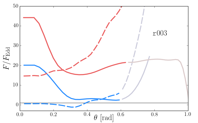
Figure 7 shows the angular distribution of the (time- and azimuth-averaged and symmetrized) radiative and kinetic fluxes of energy in the funnel/outflow region for three simulations (top to bottom): r001, r011, and r003. Blue and red lines correspond to fluxes measured at and , respectively. Solid and dashed lines denote the radiative and kinetic energies, respectively.
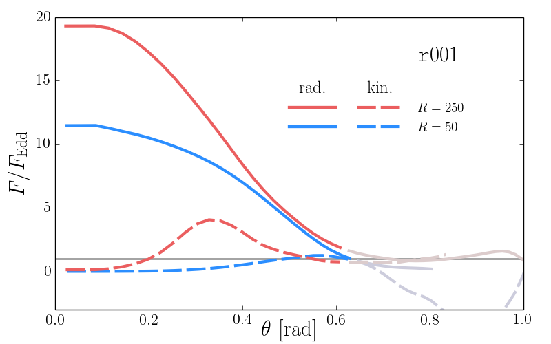
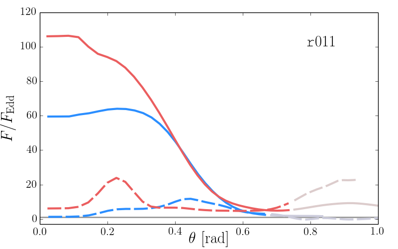
For the fiducial model (top panel, ) the energy flux (as discussed in the previous section) is dominated by radiation. The angular distribution of radiative flux follows roughly a Gaussian with half-maximum width at . The maximal flux at radius is ; it increases to at . The radiative fluxes decline significantly with increasing polar angle . For an observer at () the observed flux (and the inferred source luminosity) is only .
The numbers given above are meaningful for the optically thin region but less so for other angles where the wind is optically thick. In these regions, there is still significant interaction between gas and radiation. The radiation is likely to accelerate the gas further and the radiative flux is expected to decrease towards the Eddington limit. To study this effect quantitatively one would have to perform simulations in a much bigger box and for a much longer time.
At radius there is hardly any kinetic luminosity in the polar region of the fiducial run (r001). Only further from the BH is the gas is accelerated. In contrast to the radiative flux, the kinetic energy flux is not concentrated at the polar axis but rather in a shell around , similar to the jet/wind boundary discussed in Sądowski et al. (2013b). For the fiducial model accreting at the maximal kinetic flux at that inclination equals .
The angular profiles for the run with a rotating BH (r011) look qualitatively similar to the profiles of the fiducial run. However, the magnitudes of the fluxes are much higher, reflecting the increased efficiency of accretion due to energy being extracted from the BH. The maximal radiative and kinetic fluxes at the axis at exceed and , respectively.
A larger mass accretion rate changes the picture significantly. The third panel of Fig. 7 shows the angular profiles of fluxes for run r003. The radiative flux is still beamed at the axis, and the maximal flux exceeds at . The kinetic energy flux has a different shape than it used to. It is no longer concentrated in a shell but increases with angle, reflecting the fact that the wind carries a significant amount of energy over a wide solid angle. However, even at the axis, the kinetic energy flux is much higher than in the fiducial model — it now exceeds at . The kinetic flux in the funnel is a result of radiative energy being converted into kinetic energy within the optically thick region (Sądowski & Narayan, 2015b).
The angular distribution of energy fluxes discussed above should be considered only approximate due to the limitations of the M1 closure scheme adopted in this work. Most importantly, we evolve only the first moments of the radiation field instead of evolving specific intensities directly as in Jiang et al. (2014a) and Ohsuga & Takahashi (2015). The radiation observed by a distant observer should, in principle, be calculated as an integral of the specific intensity pointing towards the observer over the whole accretion disk. The local radial flux gives only an approximation of this quantity. Furthermore, the M1 closure is known to have difficulties in treating the region closest to the polar axis. We have substantially mitigated this problem by including an extra radiative viscosity (Sądowski et al., 2015a), but the coefficients involved had to be chosen somewhat arbitrarily.
5 Photon trapping
At the time the thin disk theory was established (Shakura & Sunyaev, 1973; Novikov & Thorne, 1973), it was commonly understood that the standard radiation pressure dominated disk can extend up to and above the critical Eddington accretion rate (equation 6). Once the Eddington limit is exceeded, it was predicted that the most energetic, inner region would attempt to produce a luminosity exceeding the Eddington value and this would produce a radiatively driven outflow inside the so called spherization radius. At the same time the wind would modify the accretion rate on the BH.
This picture did not take an important effect into account. When the accretion flow is very optically thick, photons do not have enough time to diffuse vertically to the disk photosphere before they are dragged radially inward by the accreting gas and advected into the BH. This effect was described in a simple spherical context by Begelman (1978) and included for the first time in a full-fledged accretion model by Abramowicz et al. (1988) who constructed the so-called slim disk model. These authors predicted that the radiative luminosity would no longer scale with the accretion rate above the critical rate. Also, in priniciple, the slim disk state would prevent the spherization phenomenon.
As we have shown in the previous section, and as we will explain in greater detail here, the truth is in between — there is a region, but only near the axis, where locally flux is significantly super-Eddington and where radiation drives gas out of the disk, but at the same time photons are trapped and advected towards the BH in the inflow region near the equatorial plane.
In this section we try to answer the question: where is photon trapping effective or, in other words, where is the trapping radius, the border between the radiatively inefficient (slim disk) and radiatively efficient (thin disk) regimes?
5.1 One-dimensional, luminosity-based trapping radius
It is relatively straightforward to define the trapping radius in a spherically symmetric flow (Begelman, 1978). Assuming a Bondi-like flow, we can compare the local outward radiative diffusion velocity to the local gas inflow velocity and thereby estmate
| (17) |
This approach gives only an upper limit on the location of the trapping radius in a real accretion flow; accretion disks are not spherically symmetric but have low density polar regions where radiation can more easily escape, and also the inflow velocity near the equatorial plane is significantly lower than the free-fall velocity assumed in the Bondi model (Sądowski et al., 2014).
The simplest way of estimating the location of the trapping radius numerically is to look at the net flux of radiation, e.g., the dashed lines in Fig. 5. Negative values mean that more photons were moving inward (mostly because they are dragged by optically thick gas) than outward. The radius at which the radiative luminosity goes to zero could then be defined as the trapping radius. This approach is simple and provides a single effective trapping radius. It does not, however, account for the non-uniform structure of the disk – photons easily leave the system at the axis and are more effectively trapped near the disk mid-plane. The present simple definition weights both effects and provides some kind of an average. By this definition, for simulations r001 and r020, the effective trapping radius is located around . Model r003, which has a significantly larger accretion rate, has almost the same trapping radius, . Model r011, with a rotating BH, produces much more powerful radiation flux along the axis, and correspondingly the effective trapping radius is much closer to the BH (, although the trapping in the bulk of the disk is as effective as in the other cases). A caveat: The values given above for the simulations with non-rotating BHs should be taken with caution, because the bulk of the disk is outside the inflow/equlibrium region at these radii.
5.2 Two-dimensional trapping - importance of the diffusive flux
Because of the limitations of the definition given in the previous section, we discuss here a different approach which, in particular, seeks to account for local properties of the flow.
Jiang et al. (2014b) calculated energy-weighted, vertically integrated, radial and vertical velocities of radiation transport. By comparing the two one can distinguish whether more energy flows up (away from the midplane) or inward (towards the BH). not adequate to say where the photon trapping is effective because it does not gives no importance to diffusion. The vertical flow of radiation could be the result of advection (in a wind) or turbulence Jiang et al. (2014b). Thus, while it is a good way of comparing vertical and radial energy transfer, it provides no information on the transport mechanism.
Below we attempt to quantify photon trapping by calculating the fraction of the total radiative flux that comes from diffusive transfer. To estimate the diffusive flux we use the moment equations (3), assuming and a diagonal form of the radiative stress energy tensor in the fluid frame (), to obtain
| (18) |
which is the standard diffusive flux formula (Rybicki & Lightman, 1979). This expression should be used only inside the optically thick parts of the disk where the Rosseland approximation is satisfied.
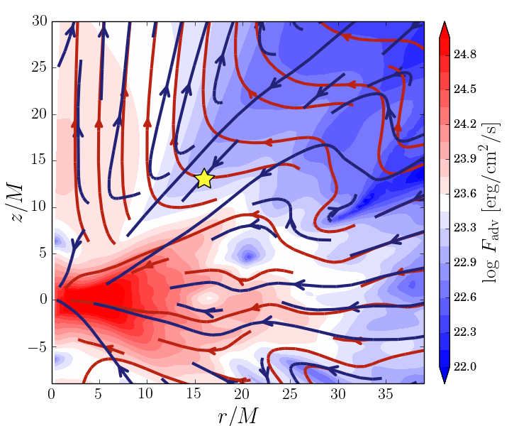
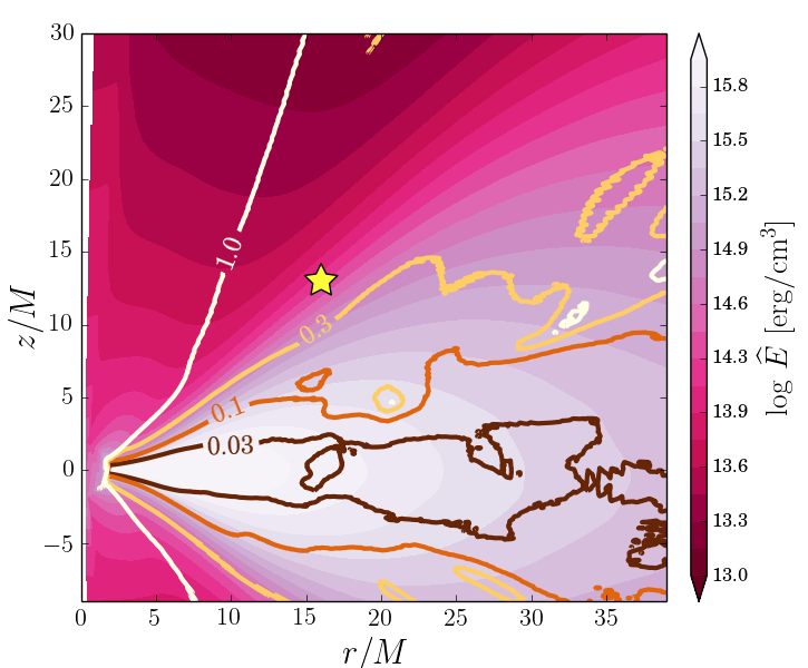
The top panel of Fig. 8 shows the magnitude (colors) and direction (red streamlines) of the total radiative flux, , for the fiducial model r001 which accretes at . Deep in the disk the radiation flows towards the BH, while the polar region is filled with optically thin radiation escaping along the axis. There is a transition region at intermediate angles, , where radiation relatively smoothly switches from flowing radially inward to flowing outward.
Blue streamlines in the same panel show the average gas velocity. If all the radiative flux was coming from photons advected with the gas, the total radiation flux vectors would follow everywhere the direction of the gas velocity. The agreement between the two sets of streamlines is very deep inside the disk, where both gas and radiation flow inward. This is where gas is most optically thick and where one expects efficient photon trapping. The streamlines agree again in the polar region, but this is not because of photon trapping. The low optical depth allows radiation to flow independently of the gas. The funnel geometry, however, makes both gas and radiation to flow upward, and the locally super-Eddington flux accelerates gas in its direction. In the intermediate region between the funnel and the disk interior, the gas velocity and radiation flux vectors do not point in the same direction. As mentioned previously, gas flows on average radially inward in the disk and only close to the surface is it blown away, causing the velocity streamlines to turn rapidly outward. Radiation flux, on the other hand, changes direction rather smoothly. This difference between gas and radiation streamlins shows that there must be an additional component of the total flux besides the advective photon transport. This is of course diffusive transport.
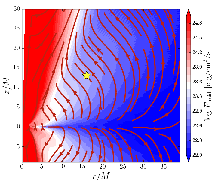
The middle panel in Fig. 8 shows on the same axes and with the same color scale the diffusive flux estimated according to equation (18). As expected, the diffusive flux follows the gradient of radiative energy density, i.e., radiation diffuses in the vertical direction away from the equatorial plane. Then, it turns smoothly towards the axis and enters the funnel region. IN the funnel itself (the red region), the estimate of the diffusive flux must be disregarded since gas there is optically thin and radiation is free streaming instead of diffusing. However, the diffusive flux estimates are trustworthy in the disk interior and the transition region between the disk and the funnel.
We now check whether the diffusive flux is, in fact, responsible for the deviation between the total radiative flux streamlines and the advected radiation flux streamlines (which would be aligned with the gas velocity). For this purpose we choose a location in the region of largest deviation, (denoted by the yellow stars in Fig. 8), and study local fluxes of radiation over time. Fig. 10 presents the estimated orthonormal polar component of the diffusive flux, calculated as,
| (19) |
as a function of the difference between the polar components of the total flux and the estimated advective flux,
| (20) |
The signs have been chosen such that the positive values correspond to fluxes pointed out of the disk, i.e., towards the axis. The sizes of markers measure the local optical depth for scattering as estimated by . The dashed line denotes . The plotted points cover the time period with cadence of .
The majority of points in Fig. 10 cluster around the dashed line, showing that the excess of radiative flux over advective flux has exactly the analytically predicted magnitude, i.e., the excess of polar radiative flux is due to diffusion. The agreement is no longer perfect at the lowest optical depths. This is natural since, when the optical depth is low, radiation decouples from the gas and the diffusive approximation no longer valid. In fact, this is where we expect the actual flux to lie below the analytically estimated diffusive flux, as is indeed seen in the plot.
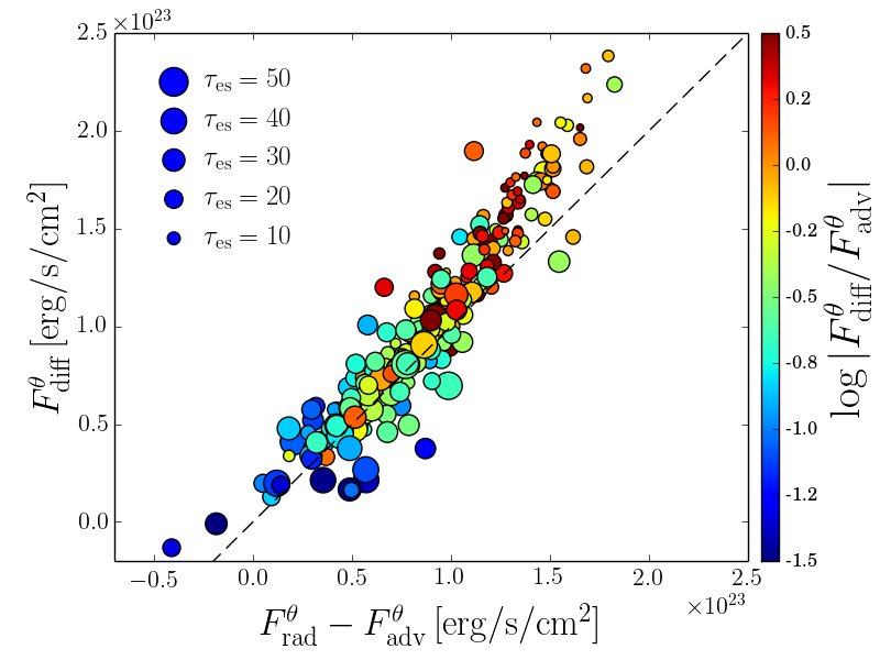
The colors of the markers in Fig. 10 denote the ratio of magnitudes of instantenous diffusive and advective fluxes. Despite the fact that the time-averaged advective flux has hardly any polar component, instantenous advective flux in direction can be more than 30 times stronger than the corresponding diffusive flux. However, because of turbulent motion of gas, it averages to a value significantly smaller than the diffusive flux. Therefore, it is the diffusive flux which dominates the average net radiation flux towards the axis near the surface of the disk.
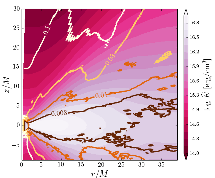
The bottom panel in Fig. 8 shows the ratio of the magnitude of the diffusive flux over the total flux plotted with contours on top of the distribution of fluid frame radiative energy density, . Deep in the disk, advection dominates strongly over diffusion. The magnitude of the former flux is times larger than the magnitude of the diffusive flux. This ratio is lower closer to the disk surface, where the density drops and the gas is no longer able to drag photons efficiently. In the transition region discussed above, the advective and diffusive fluxes have comparable magnitudes, with the diffusive flux dominating the polar component.
Figure 9 shows the same ratio of the diffusive to advective fluxes, but for simulation r003 which has almost times larger accretion rate. The larger accretion rate implies higher gas density and optical depth, and, as a result, more effective photon trapping. This is indeed the case. The advective radiative flux is now times larger than diffusive in the disk near the equatorial plane.
The properties described above show that for moderately super-critical accretion rates, , photon transport deep inside the disk is dominated by radial advection. However, diffusive transport of energy becomes important further from the equatorial plane, near the transition between the disk and the funnel, where the gradient of the energy density is large, and the optical depth of the gas is no longer huge. Radiation in the optically thin funnel follows the axis and is decoupled from gas. Because of significant photon trapping deep in the disk, only photons generated close to the surface can escape the disk and join the funnel region. This explains the relatively low radiative luminosities of our simulated disks and is in agreement with the slim disk model (e.g., Abramowicz et al., 1988; Sądowski, 2011). For higher accretion rates, the region of dominant photon trapping extends further out, not only near the equatorial plane, but also in the (now optically thick) funnel. Likewise, one expects that, for lower accretion rates, photon trapping will become less and less effective and the radiative efficiency will approach the thin disk value.
5.3 Turbulent transport
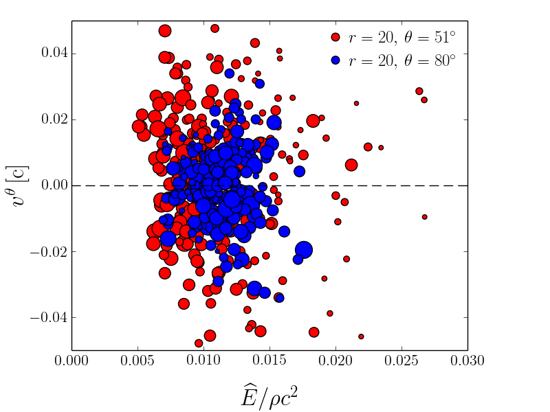
So far we have shown that the diffusive transport of radiation is important near the surface of the disk, and that the radial photon advection dominates over diffusion deep inside the disk. There is potentially one more way of radiation transfer - turbulent transport pointed out by Jiang et al. (2014b). It is effective if radiative energy is transported without transporting mass, similar to what happens in convection. Such behavior may result, e.g., from magnetic buoyancy. To assess the importance of this effect it is enough to compare the density- and radiative energy-weighted vertical velocitities of the gas. If the former is zero and the latter is not, then radiation is transported by gas without transporting mass, and hence, it is different in nature from the standard photon trapping which results from mean motion of gas.
If turbulent transport is effective then lighter gas, but containing more radiation, moves preferably towards the disk surface. In Fig. 11 we plot the polar velocity of gas as a function of radiation to rest-mass energy density ratio for the same location as in Fig. 10 (red), and for another point closer to the equatorial plane, located at (blue markers). The size of the markers denotes the optical depth as it did in Fig. 10. We see that there is no correlation between the relative radiative energy density content and the vertical motion of the gas, what suggests that the turbulent effect cannot be strong.
From the same sets of points we now calculate the density- and energy-weighted velocities, defined as,
| (21) | |||||
| (22) |
where the sums go through all the points in the set, corresponding to different moments of time and fixed location. For the point closer to the disk surface we get and . For the other point, located almost at the equatorial plane, we have, and . All the values are positive what indicates that both the gas and radiation is advected with the gas towards the equatorial plane. However, the magnitudes of these velocities are at least order of magnitude lower than of the corresponding radial velocities, what reflects the fact that the radial motion and advection dominates. One may, however, notice that the energy-weighted velocities are lower, i.e., they tend to deviate from the density-weighted velocities towards the surface. Nevertheless, the magnitude of the turbulent transport of radiation is not significant.
5.4 Advection coefficient
Defining the efficiency of photon trapping in a non-spherical accretion flow is a challenging task because of the multiple dimensions involved. Here we try to calculate the advection coefficient which estimates the fraction of photons generated at given radius that are able to escape, the rest being advected to the BH. For this purpuse, at each radius , we consider a disk annulus extending from to , and limited in to the range (Fig. 12). The polar angle range is chosen to fit the center of the transition region discussed in the previous section where the radiation flux in the fiducial model is dominated by its polar component. The annulus covers extends over in azimuthal angle. From the time averaged disk properties we extract luminosities of the radiative flux that crosses each surface of the annulus. For the radial sides, we compute
| (23) |
where the integration takes place either at the inner edge or at the outer edge . The fluxes crossing the top and bottom surfaces are similarly integrated to give,
| (24) |
where the integration is done at fixed polar angles, .
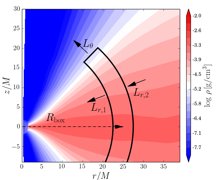
The integrated flux incoming through the outer radial sufrace tells how much radiation is advected into the volume. The corresponding luminosity crossing the inner surface tells how much radiation is advected out of the same volume. Meanwhile, the total radiation generated within the annulus is . Thus divided by the latter quantity measures the fraction of energy that is advected radially, whereas over the same quantity measures what fraction of the radiative energy escapes through the top and bottom surfaces. This then motivates the following definition of the advection coefficient, ,
| (25) |
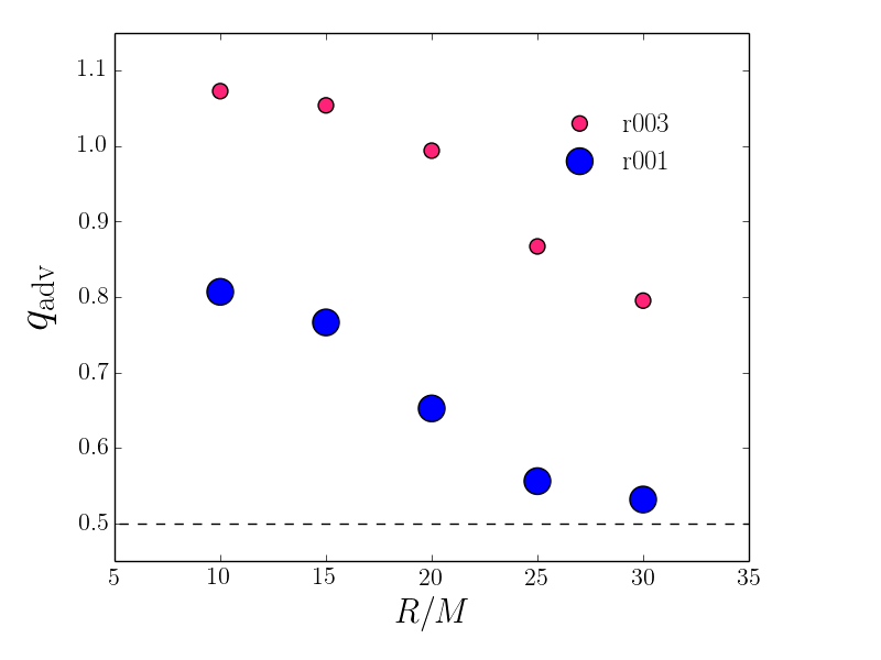
In the limit of a radiatively efficient disk we would have and . In the opposite limit of an advection-dominated flow we expect and . Tehrefore, it is natural to define the effective trapping radius as the location where , i.e., where half the radiation generated at that radius manages to escape and half is advected to the BH.
Figure 13 shows the above advection coefficient as a function of radius for the fiducial model r001 and the large accretion rate model r003 (the chosen vertical size of the box corresponds to the region of purely polar radiative flux only for the former). For the fiducial simulation, the advection factor increases towards the BH, as expected because of increasing inflow velocity. At radius we find which means that only of photons generated at that radius manage to escape and enter the funnel. The coefficient drops down to at the edge of the inflow/outflow equilibrium region (). The profile suggests that the effective photon trapping radius, defined by , is probably around (the point plotted at is outside the region of inflow equilibrium and is a little suspect).
The efficiency of advection for the simulation with higher accretion rate (r003) is significantly larger because of the larger optical depth. Even at radius only of photons escape the disk. In the innermost regions of this model, exceeds , reflecting the fact that the top-bottom luminosities are negative, i.e., photons are brought into the box, and no radiation escapes.
In our analysis in this subsection we focused solely on the radiative energy flux. In general, one should include also the flux of mechanical energy because dissipation may result in kinetic energy leaving the box. Including this component hardly affects the values of the advection coefficient calculated above.
6 Variability
Radiation coming from accretion disks is known to be highly variable (e.g., Done et al., 2007). In case of galactic BH binaries, this variability takes place on short timescales (the horizon crossing time for a BH is ). The variability is strongest in the hard state, and weakest in the thermal state. However, even in the latter, the power spectrum is far from featureless.
Studying variability is a powerful tool in understanding accretion flows. The characteristic frequencies tell us where the modulated radiation come from. Features in the power-spectrum, e.g., quasi-periodic oscillations or breaks, can manifest more subtle properties of the disks (e.g. Ingram et al., 2009; Wellons et al., 2014). Modeling the variability and its power spectrum has so far been limited mostly to analytical models. However, the dynamics of the gas and the properties of the radiation field are complicated and highly non-stationary, so the analytical approach is limited, and ultimately we should model variability using time-dependent three-dimensional simulations.
However, this approach is not straightforward. Numerical modeling of radiation in MHD codes is limited by a number of factors. First of all, radiation is solved for in the grey approximation and some arbitrary (usually blackbody) shape is often assumed for the spectrum. Secondly, general relativistic effects are rarely included. Moreover, Comptonization is either neglected or treated in a crude way. Last but not least, various approximations for radiation closure are adopted (with the exception of direct radiation transfer solvers operating on a fixed grid of angles, as implemented recently by Jiang et al. (2014a) and Ohsuga & Takahashi (2015)). Simplistic closure schemes may limit the information available for calculating the visible spectra.
The most reasonable way to proceed is to take the global, time-dependent output of a disk simulation and postprocess it with a sophisticated radiation (and only radiation) solver which will not be as limited as full radiation-MHD simulations. Such codes, which solving the frequency-dependent radiative transfer equation and account for relativistic effects and Comptonization have recently been developed (e.g. Zhu et al., 2015) and are expected to be soon available for spectral modeling.
In the meantime, we attempt to directly estimate the variability of light curves from the simulations with KORAL described in this paper. Because of the limitations mentioned above, in particular the fact that we evolve only the first moments of the radiation (M1 closure), our approach is expected to provide only a rough qualitative understanding of the temporal properties of radiation coming from super-Eddington accretion flows.
6.1 Light curves
In principle, the observer is located at infinity, i.e, . The correct way of measuring the radiation reaching a distant observer is to integrate the specific intensities pointing towards the observer at the outer edge of the computational box. However, because of the limited range of inflow/outflow equilibrium near the equatorial plane, we are limited only to studying light escaping in the polar region near the axis, where the disk solution has converged to large enough radii. Moreover, the size of our computational box is obviously limited and we cannot measure the radiative fluxes at radii larger than . Even if the duration of simulation was infinite, the photosphere would be located beyond the domain boundary except in the polar region, and even there we resolve the photosphere only at the lowest accretion rates.
Because of the limitations mentioned above, we decided to estimate the light curve by looking at the local flux of radiation at some location inside the polar region. To be sure that the light curve measured in this way is close to the light curve seen from infinity, we insist that the radiation is already decoupled from the gas; otherwise, continued interaction with (and acceleration of) the gas could drastically change the properties of the radiation that finally escapes. Once this condition is satisfied, and provided there is little radiation coming from other regions of the disk towards the chosen line of sight, the shape of the light curve should be independent of the radius it is measured at, only shifted in time by the light crossing time. Below we test if this criterion is satisfied for the locally measured fluxes in simulation r001.
| 0.20 | 1.96 | |
| 0.23 | 0.64 | |
| 0.23 | 0.58 |
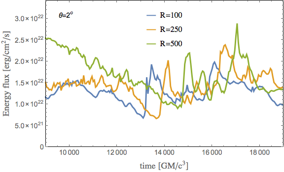
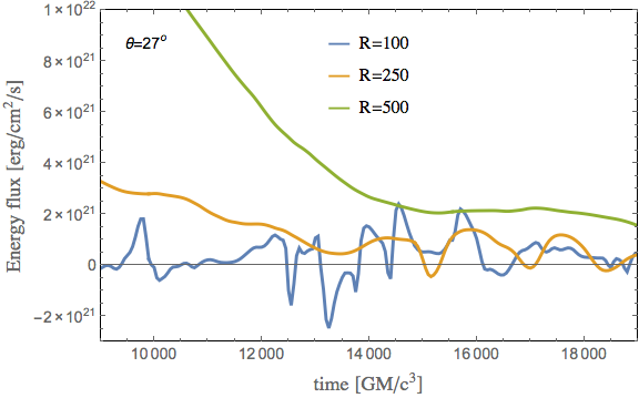
To extract the light curves we choose an arbitrary slice through the poloidal plane, define the inclination angle, and choose a radius where we measure the energy fluxes. Then we take the radial component of the lab-frame radiative flux, , and plot it as a function of time. Fig. 14 shows such time series extracted at two polar angles ( and , top and bottom panels, respectively), and at three radii (, , and ). Only the second half of the simulation, when the accretion has settled down to a quasi-steady state (compare Fig. 1), is shown. The fluxes measured at and were scaled to account for geometrical expansion to match the magnitude of the flux at .
The first panel corresponds to radiation escaping along the axis. For model r001, gas is optically thin on the axis at all radii so one may expect the measured fluxes not to depend on the radius where the measument is performed. This is indeed the case. The profiles resemble each other to a good accuracy, at least for , with the shift in time reflecting the propagation of light in the vertical direction. This gives some confidence that the light curve we calculate is what a distant observer might see. It is interesting, however, that the propagation speed down the funnel to match the time delay between radii is less then the speed of light. It equals approximately which is the characteristic velocity of the radiation field (the velocity of the radiation rest frame) inside the funnel. It is determined by the geometry of the funnel and the effect was discussed close to 40 years ago by Sikora (1981). Basically, not all the photons go straight up; a significant fraction go sideways and some even go backward. The characteristic velocity is in some sense the average radial photon velocity.
The short duration of the light curves ( real time for a BH)) do not allow us to calculate power spectra. Instead, we calculate the fractional variability through
| (26) |
where denotes the standard deviation and stands for the mean luminosity. The second column of Table 3 gives the fractional variability calculated for light curves in the top panel of Fig. 14. Note that the fractional variability does not change much with radius. In particular, it does not change between and which again reflects the fact that the radiation flowing along the axis has established its temporal profile and is not affected any more by interaction with gas or radiation at larger radii.
The bottom panel of the same figure presents radiative light curves measured at the same radii but at a larger inclination angle, , which corresponds to the edge of the funnel region, but located in the optically thick portion of the gas. One may expect therefore, that the radiation interacts (is absorbed or emitted) with the gas up to large radii, even out to the domain boundary, and that the radiation fluxes measured at different radii will differ, even after taking the geometrical factor into account. The radiation flux measured at (blue line) varies significantly, reaching at moments negative values. This behavior reflects the motion of the gas to which the radiation is coupled to. The gas on average moves out, but temporarily can move inward, dragging photons with it. The light curves become more smooth and the luminosities become larger in magnitude with increasing radius. These result from the fact that the gas moves in a more laminar way further out, and that radiation originating from a larger volume contributes to the measured luminosity. As a result, the corresponding fractional variability (third column of Table 3) decreases significantly with increasing radius.
Because of the significant coupling with gas, and the fact that we do not resolve the photosphere (because the computation box is not large enough box and the duration of the simulation is too short), the light curves for the larger inclination angle are not reliable. Only the light curve for radiation leaving the system almost exactly along the axis is robust. However, even this will not be the case if the accretion rate is larger since then, even on the axis, the photosphere will be located at large radii. This is a severe limitation for studies of variability in super-critical disks. In contrast, for thin disks, the photosphere is close to the equatorial plane and one can hope to extract useful variability information from simulations.
7 Axisymmetric simulations
Angular momentum in accretion disks is transported by MHD turbulence, which is driven primarily by the magnetorotational instability (Balbus & Hawley, 1991). Turbulent motion in the poloidal plane leads not only to the exchange of angular momentum, but also to dissipation of magnetic field. In axisymmetric simulations this process quickly causes the magnetic field to decay, and at some point, shortly after the beginning of a simulation, typically after , the accretion stops. In reality, the poloidal magnetic field is revived by a dynamo process which results from breaking axisymmetry — non-axisymmetric perturbation can “rotate” toroidal field into the poloidal plane and thereby regenerate poloidal field. Three dimensional simulations of turbulent magneto-fluids in shearing boxes (and also in global models) have shown that the saturated state is characterized by an average toroidal-to-radial magnetic field ratio , and an average magnetic-to-gas pressure ratio . There is no way of obtaining such a saturated state in pure axisymmetric simulations.
On the other hand, the advantages of assuming axisymmetry and simulating accretion disks in two dimensions are obvious – such simulations are cheaper by more than an order of magnitude in terms of the required computational time. Until recently, however, axisymmetric simulations were limited to extremely short durations because of the rapid decay of the magnetic field mentioned above. The situation has now changed. Sądowski et al. (2015a) introduced a mean-field model of the dynamo effect which mimics the properties of three-dimensional MRI-driven turbulence but can be applied to axisymmetric simulations. In this approach, the properties of the magnetic field are driven towards the prescribed characteristics of the saturated state, described by parameters and . This is achieved by “pumping” new vector potential into the MHD flow, leading to a correction to the existing poloidal field. The poloidal field is enhanced in regions where the magnetic field is too weak, and the toroidal component of the field is damped in regions were the magnetic pressure exceeds the prescribed saturation value. It has been shown that such an approach successfully allows for arbitrarily long simulations and indeed leads to a saturated state similar to that seen in three-dimensional simulations.
Our aim in this section is to compare the properties of three-dimensional simulated super-critical, radiative disks with corresponding two-dimensional axisymmetric simulations. For this purpuse we simulated an additional model (d300) which was run in axisymmetry, with grid points in the poloidal plane, and initialized in an identical manner to the fiducial model r001 (see Table 1). We used the mean-field dynamo model with the fiducial saturated state parameters and . Model d300 was run until , an order of magnitude longer than the three-dimensional model r001, yet it required less computer resources by almost an order of magnitude. This enormous saving is the reason why we feel it is important to explore the two-dimensional option fully.
The left- and right-most panels in Fig. 6 compare the density distribution on the poloidal plane, gas velocities, radiative flux, location of the photosphere, and border of the outflow region in the three- (r001) and two-dimensional (d300) simulations. Qualitatively, the two solutions (after averaging over time and azimuth in the three-dimensional case) agree very well. The gas shows the same dynamical properties, with outflow taking place only in the funnel region, the magnitude of the radiation flux is similar, and the photosphere is located at the same place. The only noticeable difference is near the disk surface at larger radii () where the two-dimensional run shows more significant vertical motion. This may be because of the approximate treatment of the dynamo effect which is constructed to satisfy only the vertically averaged criteria, without paying too much attention to the vertical profile of magnetic field properties. It should also be kept in mind that the three-dimensional model has achieved inflow/outflow equilibrium only for . It could be that even the relatively minor differences in structure between the three- and two-dimensional models would be reduced once the former is run for a much longer time and reaches equilibrium out to radii . Very expensive simulations would be required to verify if this explanation is correct.
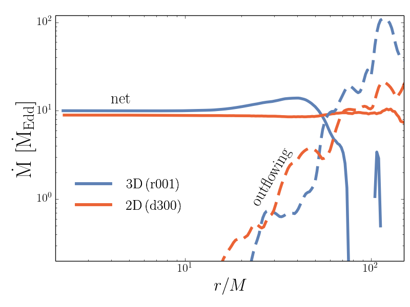
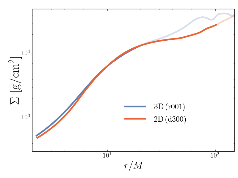
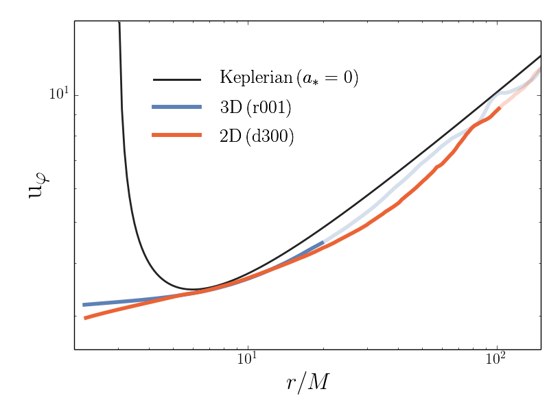
To quantify the comparison between models r001 and d300, we have calculated radial profiles of the accretion rate, surface density, and density-weighted angular momentum for the two runs. They are shown respectively in the top, middle, and bottom panels in Fig. 15. The net accretion rates are similar. The two-dimensional simulation has , roughly lower than the three-dimensional model, but close enough to allow a meaningful comparison of the two models. The extent of the flat section of the net accretion rate profile is a benchmark for the extent of inflow/outflow equilibrium. As discussed earlier, for simulation r001 the equilibrium region extends only to . Thanks to the long duration of the d300 simulation, the equilibrium region here extends much further out, to . Dashed lines in the same panel show the rate of mass lost in the wind. It is comparable for the two runs, and suggests that the amount of outflowing gas equals the net accretion rate around radius .
The middle panel in Fig. 15 compares the surface density profiles. They are indistinguishable where the equilibrium regions of the two simulations overlap (the sections of the curves outside the equilibria are marked with shaded colors). Similarly, the profiles of angular momentum also match well (bottom panel) except in the plunging region inside the marginally stable orbit, where the two-dimensional run results in a slightly lower angular momentum. This difference probably arises from the fact that the dynamics of the flow and the properties of the magnetic field in this region are not governed by the combined effects of shear and the dynamo process (Penna et al., 2013b).
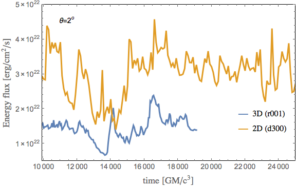
In summary, the above comparisons indicate that the average properties of the two- and three-dimensional simulations are remarkably similar. The temporal properties, on the other hand, are significantly different. In Fig. 16 we show radiative light curves measured at angle and at radius (the light curve of simulation r001 corresponds to the one shown in the top panel of Fig. 14 for this particular radius). The two-dimensional run resulted in noticeably larger radiative luminosity in the outflow region and larger beaming towards the axis (but the same total luminosity, see Table 2). As a result, the flux in the axisymmetrical model is twice as large, and at the same time, it is also more variable – its fractional variability () significantly exceeds that of the three-dimensional run (). The difference must come from the fact that the axisymmetrical simulation neglects the many non-symmetrical modes which develop in three-dimensional simulations. Variations in independent patches in azimuth would tend to wash each other out when averaged, but no such averaging would be present in an axisymmetric model.
8 Summary
In this paper we presented a set of four three-dimensional simulations of black hole super-critical accretion disks. Two of the simulations accreted roughly at (models r001 and r020), the third simulation (r003) had a significantly larger accretion rate of , and the fourth simulation (r011) was characterized by a rotating BH with spin and accreted roughly at . The fifth simulation we presented was performed assuming axisymmetry (hence this was a two-dimensional simulation) and corresponded to roughly accretion rate. All the simulations resulted in optically thick and geometrically thick turbulent accretion disks. In the course of this study we reached a number of conclusions:
-
1.
Photosphere: Only for accretion rates does the photosphere extend down to the horizon, i.e., only for such low accretion rates will an observer at infinity viewing down the axis be able to see the innermost region of the accretion disk. For larger accretion rates, an on-axis observer will only observe a photosphere which is located relatively far from the black hole. In fact, even for relatively low accretion rates , the optically thin region is limited to polar angles . For larger inclinations, an observer would only see the photosphere of the accretion disk located at large distance from the BH, often outside the computational box of the simulations. The limited box size and duration of the simulations do not allow us to study the radiation coming from such distant photospheres in any detail. We expect, however, that the spectrum of any such radiation will be relatively soft, because of the large distance from the BH, and that the observed isotropic-equivalent luminosity will not significantly exceed the Eddington value – a super-Eddington flux in an optically thick wind causes acceleration of the wind and reduces the radiative flux towards the Eddington limit.
-
2.
Stagnation radius: For the simulations with the lowest accretion rates (), the stagnation radius in the funnel, , which separates an inner region where gas falls into the BH from an outer region where gas flows out, is located near the BH (). In the case of simulation r011 (with a spinning BH), where the extraction of the rotational energy of the BH increases the energy flux through the funnel, the stagnation radius is very close to the horizon. For the run with the largest accretion rate (r003), the stagnation radius moves significantly out – all gas in the funnel within falls on the BH. This is a result of the increased optical depth of the gas, which traps photons and effectively suppresses the outflow of radiation up to this radius.
-
3.
Total luminosity: All the simulations with non-rotating BHs show the same total efficiency of roughly , approximately a factor of two less than the efficiency of a standard thin accretion disk. We obtain similar ratio of efficiencies for the simulation with a rotating BH (), for which the measured total efficiency was . These efficiencies were calculated from the total luminosity in all forms of energy: radiative, kinetic, magnetic, thermal and binding (only rest mass energy was not included). The total luminosity is thus fundamental and represents the total energy deposited at “infinity” (the interstellar medium). There is no unique way of decomposing the above total luminosity into its constituent parts because of the limited size of the inflow/outflow equilibrium region in the simulations. When measured at the limit of inflow-outflow equilibrium ( in the disk interior), energy balance is dominated by the binding energy flux. This energy must be transformed into other forms of energy before reaching infinity (where the binding energy is zero).
-
4.
Radiative luminosity: Radiative luminosity can be measured reliably only inside the optically thin funnel region near the axis; here, radiation is decoupled from gas, and whatever radiation is flowing outward is guaranteed to reach the observer. However, only the simulations with the lowest accretion rates show an optically thin region inside the computational domain at all. Even in these cases, the optically thin radiative luminosity increases with radius (Table 2) because of radiation flowing into the funnel from the disk at larger radii. To obtain a useful estimate of the net radiative luminosity from the funnel, we would have to simulate accretion flows in much bigger computational box and for a much longer time. This is presently impractical. The radiative luminosities measured at radius in the optically thin and outflowing regions are quite low. For accretion rates near and a non-rotating BH, only of the total liberated energy of (mentioned above) comes out as optically thin radiation escaping through the funnel. The kinetic luminosity exceeds the radiative luminosity for the largest accretion rate considered, where the coupling between radiation and gas in the funnel is strongest, resulting in radiative acceleration of gas (Sądowski & Narayan, 2015b). The luminosities are significantly larger for the simulation with a rotating BH because the BH spin provides an extra source of energy.
-
5.
Beaming: We have confirmed that radiation is beamed along the polar axis and the radiative fluxes here can be significantly super-Eddington. For the fiducial accretion rate of , the simulations with non-rotating and spinning BHs show radiative fluxes of and , respectively, on the axis. In contrast, the kinetic energy is not beamed on the axis but peaks (Fig. 7) either in a conical shell (for lower accretion rates) or in the wind region (for larger accretion rates).
-
6.
Photon trapping: We compared the total flux of radiation with the diffusive flux and showed that, for the accretion rates considered, advection of radiation (photon trapping) dominates over diffusive transport deep inside the disk. For , the advective flux is more than times stronger than the diffusive flux near the equatorial plane, and this ratio increases by at least an order of magnitude when the accretion rate grows to , which is explained by the increased optical depth. Closer to the disk surface or funnel boundary, the diffusive flux of radiation dominates, which ultimately contributes to the optically thin radiation escaping through the funnel. This flux also helps to drive gas away from the disk surface into the funnel.
-
7.
Radiation transport An analysis of our simulations shows that radiation transport is dominated by advective and diffusive transport. We do not see a significant component of turbulent radiative transport.
-
8.
Advection factor: For the fiducial model () we estimated the fraction of photons generated in the disk that manage to escape vertically and enter the optically thin funnel region. At radius , only of photons leave the disk while end up in the BH. Corresponding numbers at radius are approximately and , respectively. This suggests that the effective trapping radius, where half the photons escape from the disk and half fall into the BH, is located at for .
-
9.
Variability: We attempted to extract from the simulations (frequency integrated) lightcurves as seen by observers at infinity. Because of the limited size of the equilibrium region, and the fact that the photosphere is located close to the axis even for the lowest accretion rate considered, we were able to obtain robust light curves only for radiation escaping along the axis, and that too only for the fiducial model. Extracting variability information from simulations of optically thick and geometrically very thick disks is, and will remain to be, challenging. One may expect that thin disks, with photospheres much closer to the equatorial plane, will be more amenable to study.
-
10.
Impact of the BH mass: We performed one simulation (r020) with BH mass , which had the same Eddington-scaled mass accretion rate as the fiducial model (r001). The properties of the two simulations, after scaling down the latter by appropriate factors, were quite similar; in fact, it was difficult to distinguish the two (compare Fig. 6). This is because electron scattering opacity dominates in both simulations, and under these conditions the accretion equations scale very simply with BH mass. For much larger BH masses (corresponding to the SMBH regime), the absorption opacity will no longer be negligible and this will break exact scaling.
-
11.
Axisymmetric simulations: We compared the properties of the fiducial three-dimensional simulation (r001) with a two-dimensional axisymmetric simulation (d300) that made use of an artificial magnetic dynamo and accreted at roughly the same rate. We showed that the time-averaged properties of the two simulations were remarkably similar. Because of the significantly lower computational cost, we were able to run the axisymmetric simulation for a much longer time and obtained a significantly larger equilibrium region (extending up to instead of only in the case of the 3D model). Thus, two-dimensional axisymmetric simulations (with magnetic dynamo) are a cheap and promising method for running models for long times and thereby extending the range of radii over which one obtains useful information. However, this must be done with caution. While time-averged quantities appear to be reliable, we note that the temporal properties of the 2D and 3D runs were different. In particular, because of the lack of non-axisymmetric modes in the axisymmetric simulation, it showed much larger variability in the radiative flux flowing out along the axis.
8.1 Comparison with other studies
Our study is the first to explore the parameter space relevant to radiation-dominated BH accretion disks using three-dimensional, general relativistic, radiation-MHD simulations. The properties of the simulated super-critical disks described in this work are qualitatively in agreement with previously published global simulations. In particular, significant photon trapping was identified already by Ohsuga & Mineshige (2007), and confirmed more recently by Sądowski et al. (2014) and McKinney et al. (2014). The total luminosities given in the present work are also close to those obtained in the latter studies. The same is true for radiation beaming and the radiative luminosity of the funnel.
There are a number of differences between our results and those described in Jiang et al. (2014b). The model presented in the latter work, which had an accretion rate of , can be directly compared to our fiducial model r001. Jiang et al. (2014b) found a very different spatial distribution of gas compared to our run; their disk is strongly concentrated at the equatorial plane whereas our disk is not. Perhaps because of this, they obtained a powerful radiative flux from the innermost () region; in fact, nearly all of their radiative luminosity, which is of the order of , comes from such small radii. Our simulations show a similar total efficiency (), but only a small fraction of the energy escapes as radiation at small radii.
Jiang et al. (2014b) used a Newtonian code with cylindrical coordinates (and a “cylindrical BH” with radius ). Their simulation was intialized with a different and more strongly magnetized torus compared to ours. They implemented a sophisticated radiation transfer solver which evolved in real time a number of specific intensities. In comparison, our simulations were done with the M1 closure scheme, which means that we evolved only four independent radiation quantities in each cell. On the other hand, Jiang et al. (2014b), for the sake of performance, had to make some approximations when treating the interactions between gas and radiation666These approximations were avoided by Ohsuga & Takahashi (2015), who implemented sub-stepping in their implicit solver, but otherwise used the same ideas as in Jiang et al. (2014b).. Which of these factors is responsible for the large discrepancy between their study and ours is presently unclear.
9 Acknowledgements
The authors thank Jean-Pierre Lasota for his comments. AS acknowledges support for this work by NASA through Einstein Postdoctotral Fellowship number PF4-150126 awarded by the Chandra X-ray Center, which is operated by the Smithsonian Astrophysical Observatory for NASA under contract NAS8-03060. AS thanks Harvard-Smithsonian Center for Astrophysics for hospitality. RN was supported in part by NSF grant AST1312651 and NASA grant TCAN NNX14AB47G. The authors acknowledge computational support from NSF via XSEDE resources (grant TG-AST080026N), and from NASA via the High-End Computing (HEC) Program through the NASA Advanced Supercomputing (NAS) Division at Ames Research Center.
References
- Abramowicz et al. (1988) Abramowicz, M. A., Czerny, B., Lasota, J. P., & Szuszkiewicz, E. 1988, Astrophysical Journal, 332, 646
- Afshordi & Paczyński (2003) Afshordi, N., & Paczyński, B. 2003, Astrophysical Journal, 592, 354
- Avara et al. (2015) Avara, M. J., McKinney, J. C., & Reynolds, C. S. 2015, arXiv:1508.05323
- Balbus & Hawley (1991) Balbus, S. A., & Hawley, J. F. 1991, Astrophysical Journal, 376, 214
- Begelman (1978) Begelman, M. C. 1978, Monthly Notices of the Royal Astronomical Society, 184, 53
- Davis et al. (2005) Davis, S. W., Blaes, O. M., Hubeny, I., & Turner, N. J. 2005, Astrophysical Journal, 621, 372
- Done et al. (2007) Done, C., Gierliński, M., & Kubota, A. 2007, Astronomy and Astrophysics Review, 15, 1
- Fragile et al. (2014) Fragile, P. C., Olejar, A., & Anninos, P. 2014, arXiv:1408.4460
- Frank et al. (1985) Frank, J., King, A. R., & Raine, D. J. 1985, Cambridge and New York, Cambridge University Press, 1985, 283 p.,
- Gammie et al. (2003) Gammie, C. F., McKinney, J. C., & Tóth, G. 2003, Astrophysical Journal, 589, 444
- Hubeny & Hubeny (1997) Hubeny, I., & Hubeny, V. 1997, Astrophysical Journal Letters, 484, L37
- Igumenshchev et al. (2003) Igumenshchev, I. V., Narayan, R., & Abramowicz, M. A. 2003, Astrophysical Journal, 592, 1042
- Ingram et al. (2009) Ingram, A., Done, C., & Fragile, P. C. 2009, Monthly Notices of the Royal Astronomical Society, 397, L101
- Jiang et al. (2012) Jiang, Y.-F., Stone, J. M., & Davis, S. W. 2012, Astrophysical Journal Suppl. Ser., 199, 14
- Jiang et al. (2014a) Jiang, Y.-F., Stone, J. M., & Davis, S. W. 2014, Astrophysical Journal Suppl. Ser., 213, 7
- Jiang et al. (2014b) Jiang, Y.-F., Stone, J. M., & Davis, S. W. 2014, Astrophysical Journal, 796, 106
- Kawashima et al. (2009) Kawashima, T., Ohsuga, K., Mineshige, S., et al. 2009, Publications of the Astronomical Society of Japan, 61, 769
- Komissarov (1999) Komissarov, S. S. 1999, Monthly Notices of the Royal Astronomical Society, 303, 343
- Levermore (1984) Levermore, C. D. 1984, Journal of Quantitative Spectroscopy and Radiative Transfer, 31, 149 2
- McClintock et al. (2011) McClintock, J. E., Narayan, R., Davis, S. W., et al. 2011, Classical and Quantum Gravity, 28, 114009
- McKinney et al. (2012) McKinney, J. C., Tchekhovskoy, A., & Blandford, R. D. 2012, Monthly Notices of the Royal Astronomical Society, 423, 3083
- McKinney et al. (2014) McKinney, J. C., Tchekhovskoy, A., Sadowski, A., & Narayan, R. 2014, Monthly Notices of the Royal Astronomical Society, 441, 3177
- McKinney et al. (2015) McKinney, J. C., Dai, L., & Avara, M. 2015, arXiv:1508.02433
- Möller & Sądowski (2015) Möller, A., Sądowski, A. 2015, in prep
- Narayan et al. (2003) Narayan, R., Igumenshchev, I. V., & Abramowicz, M. A. 2003, Publications of the Astronomical Society of Japan, 55, L69
- Novikov & Thorne (1973) Novikov, I. D., & Thorne, K. S. 1973, Black Holes (Les Astres Occlus), 343
- Ohsuga & Mineshige (2007) Ohsuga, K., & Mineshige, S. 2007, Astrophysical Journal, 670, 1283
- Ohsuga et al. (2009) Ohsuga, K., Mineshige, S., Mori, M., & Yoshiaki, K. 2009, Publications of the Astronomical Society of Japan, 61, L7
- Ohsuga & Mineshige (2011) Ohsuga, K., & Mineshige, S. 2011, Astrophysical Journal, 736, 2
- Ohsuga & Takahashi (2015) Ohsuga, K., & Takahashi, H. R. 2015, Astrophysical Journal, submitted
- Paczyński (2000) Paczyński, B. 2000, arXiv:astro-ph/0004129
- Penna et al. (2010) Penna, R. F., McKinney, J. C., Narayan, R., et al. 2010, Monthly Notices of the Royal Astronomical Society, 408, 752
- Penna et al. (2013a) Penna, R. F., Kulkarni, A., & Narayan, R. 2013a, Astronomy & Astrophysics, 559, A116
- Penna et al. (2013b) Penna, R. F., Sa̧dowski, A., Kulkarni, A. K., & Narayan, R. 2013a, Monthly Notices of the Royal Astronomical Society, 428, 2255
- Pozdnyakov et al. (1983) Pozdnyakov, L. A., Sobol, I. M., & Syunyaev, R. A. 1983, Astrophysics and Space Physics Reviews, 2, 189
- Rybicki & Lightman (1979) Rybicki, G. B., & Lightman, A. P. 1979, New York, Wiley-Interscience, 1979. 393 p.,
- Sądowski (2011) Sądowski, A. 2011, Ph.D. Thesis, Nicolaus Copernicus Astronomical Center, Polish Academy of Sciences, arXiv:1108.0396
- Sądowski et al. (2013) Sądowski, A., Narayan, R., Tchekhovskoy, A., & Zhu, Y. 2013a, Monthly Notices of the Royal Astronomical Society, 429, 3533
- Sądowski et al. (2013b) Sądowski, A., Narayan, R., Penna, R., & Zhu, Y. 2013b, Monthly Notices of the Royal Astronomical Society, 436, 3856
- Sądowski et al. (2014) Sądowski, A., Narayan, R., McKinney, J. C., & Tchekhovskoy, A. 2014, Monthly Notices of the Royal Astronomical Society, 439, 503
- Sądowski et al. (2015a) Sądowski, A., Narayan, R., Tchekhovskoy, A., Abarca, D., Zhu, Y., & McKinney J. C. . 2015a, Monthly Notices of the Royal Astronomical Society, 447, 49
- Sądowski & Narayan (2015b) Sądowski, A., & Narayan, R. 2015b, arXiv:1503.00654, MNRAS, submitted
- Sądowski & Narayan (2015c) Sądowski, A., & Narayan, R. 2015c, MNRAS, in press
- Schnittman et al. (2013) Schnittman, J. D., Krolik, J. H., & Noble, S. C. 2013, Astrophysical Journal, 769, 156
- Shafee et al. (2008a) Shafee, R., Narayan, R., & McClintock, J. E. 2008, Astrophysical Journal, 676, 549
- Shafee et al. (2008b) Shafee, R., McKinney, J. C., Narayan, R., et al. 2008, Astrophysical Journal Letters, 687, L25
- Shakura & Sunyaev (1973) Shakura, N. I., & Sunyaev, R. A. 1973, A&A, 24, 337
- Sikora (1981) Sikora, M. 1981, Monthly Notices of the Royal Astronomical Society, 196, 257
- Straub et al. (2011) Straub, O., Bursa, M., Sądowski, A., et al. 2011, Astronomy & Astrophysics, 533, A67
- Tchekhovskoy et al. (2011) Tchekhovskoy, A., Narayan, R., & McKinney, J. C. 2011, Monthly Notices of the Royal Astronomical Society, 418, L79
- Tóth (2000) Tóth, G. 2000, Journal of Computational Physics, 161, 605
- Wellons et al. (2014) Wellons, S., Zhu, Y., Psaltis, D., Narayan, R., & McClintock, J. E. 2014, Astrophysical Journal, 785, 142
- Zhu et al. (2015) Zhu, Y., Narayan, R., Sądowski, A., & Psaltis, D. 2015, Monthly Notices of the Royal Astronomical Society, 451, 1661