Application of the Compress Sensing Theory for Improvement of the TOF Resolution in a Novel J-PET Instrument
Abstract
Nowadays, in Positron Emission Tomography (PET) systems, a Time of Flight information is used to improve the image reconstruction process. In Time of Flight PET (TOF-PET), fast detectors are able to measure the difference in the arrival time of the two gamma rays, with the precision enabling to shorten significantly a range along the line-of-response (LOR) where the annihilation occurred. In the new concept, called J-PET scanner, gamma rays are detected in plastic scintillators. In a single strip of J-PET system, time values are obtained by probing signals in the amplitude domain. Owing to Compress Sensing theory, information about the shape and amplitude of the signals is recovered. In this paper we demonstrate that based on the acquired signals parameters, a better signal normalization may be provided in order to improve the TOF resolution. The procedure was tested using large sample of data registered by a dedicated detection setup enabling sampling of signals with 50 ps intervals. Experimental setup provided irradiation of a chosen position in the plastic scintillator strip with annihilation gamma quanta.
keywords:
Compressed Sensing , Positron Emission Tomography , Time-of-Flight1 INTRODUCTION
Positron Emission Tomography (PET) [1] is currently one of the most perspective techniques in the field of medical imaging. PET is based on the fact that the electron and positron annihilate and their mass is converted to energy in the form of two gamma quanta flying in the opposite directions. The two gamma quanta registered in coincidence define a line referred to as line of response (LOR). The image of distribution of the radionuclide is obtained from the high statistics sample of reconstructed LORs. In Time of Flight PET (TOF-PET) systems [2, 3], the applied detectors measure the difference in the arrival time of the two gamma rays which enables to shorten significantly a range along the LOR used for the reconstruction of the image.
Currently all commercial PET devices use inorganic scintillator materials, usually LSO or LYSO crystals, as radiation detectors. These are characterized by relatively long rise- and decay times, of the order of tens of nanoseconds. The J-PET collaboration investigates a possibility of construction of a PET scanner from plastic scintillators which would allow for simultaneous imaging of the whole human body. The J-PET chamber is built out from long strips forming the cylinder [4, 5]. Light signals from each strip are converted into electrical signals by two photomultipliers (PM) placed at opposite edges. It should be noted that the better the time resolutions of the detection system the better is the quality of a reconstructed images.
In this paper we will investigate the TOF resolution of a novel J-PET scanner and we will show a simple method to improve the results by applying the compressive sensing theory. In the following we define the time resolution and present shortly the method of signal normalization based on compressive sensing theory. Then we describe an experimental setup used for signal registration and present results of improving TOF resolution in 30 cm long plastic scintillator strip, read out on both sides by the Hamamatsu R4998 photomultipliers. Signals from the photomultipliers were sampled in 50 ps steps using the Lecroy Signal Data Analyzer 6000A.
2 MATERIALS AND METHODS
2.1 Definition of time resolution
In the following we will be interested in determination of moment of interaction of gamma quantum with a strip. The interaction moment () is given by:
| (1) |
where and are the arrival times to the PM1(2), respectively, is the length of whole strip, and is the effective speed of the light in used scintillator. In the recent work [6], the speed of the light in the scintillator was estimated to 12.6 cm/ns.
In order to determine the resolution (standard deviation) of thit determination an indirect method based on the estimation of the resolution of time difference () will be provided. We assume for the sake of simplicity that in Eq. 1 is known exactly. Since the time difference , we have
| (2) |
and the resolution of based on Eq. 1 may be expressed as:
| (3) |
which implies that the resolution of the determination of interaction moment () is twice better than the resolution of the time difference .
2.2 Experimental Setup
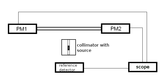
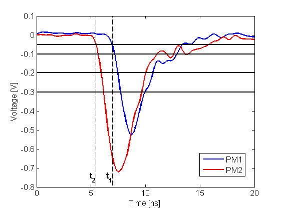
A necessary data to carry out the research have been acquired by a single module of the J-PET detector [6]. The scheme of experimental setup is presented in Fig. 1. The 30 cm long strip was connected on two sides to the photomultipliers (PMs). The radioactive source was moved from the first to the second end in steps of 6 mm. At each position, about 10 000 pairs of signals from PM1 and PM2 were registered in coincidence with reference detector. The signals were sampled using the scope with a probing interval of 50 ps. Examples of two signals registered at PM1 and PM2 are shown in Fig. 2 with blue (red) colors, respectively, for the case when the scintillator was irradiated at distance of 7 cm from PM2 (23 cm from PM1).
In the final, multi-modular devices with hundreds of photomultipliers probing with scopes will not be possible. Therefore, a multi-threshold sampling method to generate samples of a PET event waveform with respect to four user-defined amplitudes was proposed. An electronic system for probing these signals in a voltage domain was developed and successfully tested [7]. Based on the signals registered via scope, we simulate a four-level measurement with sampling in the voltage domain at 50, 100, 200 and 300 mV, indicated by four black horizontal lines in Fig. 2. It should be stressed that due to the time walk effect the resolution determined when applying the lowest threshold (50 mV) is better with respect to the resolution obtained at the highest level (300 mV). Therefore the simplest way to define the start of each pulse, times and , is to use the information from registration time at the lowest amplitude level, marked with vertical dashed lines in Fig. 2. From this one may easily estimate the resolution of and therefore the resolution of thit (see Eq. 3).
2.3 Compressive Sensing framework
Since the shape and amplitude of signals are predominantly related with the hit position, further improvement of the resolution may be provided by the analysis of the full time signals. According to the theory of compressive sensing (CS) [8, 9], a signal that is sparse in some domain can be recovered based on far fewer samples than required by the Nyquist sampling theorem. In recent articles [10, 11, 12] we have proposed a novel signal recovery scheme based on the Compress Sensing method and the statistical analysis that fits to the signal processing scenario in J-PET devices. Under this theory only a recovery of a sparse or compressible signals is possible. In articles [10, 11] the sparse representation of signals was provided by the Principal Component Analysis (PCA) decomposition. We will not describe all the steps of signal processing here, but we just state that the recovery of full time signals based on eight samples is very accurate. For further details about signal recovery scheme in the J-PET framework the interested reader is referred to Ref. [10, 11, 12].
The application of CS theory enable to take an advantage from fully sampled signals and open an area for completely new algorithms for the estimation of the values of times and (see Fig. 2). In the following we will use the recovered signals to provide the signal normalization.
2.4 Method of signal normalization
Due to the low detection efficiency of the plastic scintillators (and interaction of gamma quanta predominantly via Compton effect), low number of photons reach the photomultipliers and the charge, as well as amplitude, of signals is subject to a large variations. However, the shapes of the signals are highly related with the position of the interaction. In order to improve the time resolution, a method of signals normalization is proposed which permits to decrease the smearing of signals charge. The procedure of signal normalization is as follows.
Consider data sets representing charges of signals at PM1 and PM2 gathered for positions. The mean values of the charges at positions along the strip () at PM1, PM2 will be denoted by and , respectively. Furthermore, the standard deviation of charges at each position along the strip () at PM1, PM2 will be denoted by and , respectively.
Suppose that new pair of signals and have been recovered based on time samples registered at four amplitudes levels at PM1 and PM2, respectively. The charges of the signals, and , are calculated as an integrations of the and functions, respectively. The proposed normalization procedure qualifies a new measurement, represented by and , to the position:
| (4) |
Next, the recovered signals and are normalized according to the formula:
| (5) | |||
| (6) |
where and denote the normalized signals.
3 EXPERIMENTAL RESULTS
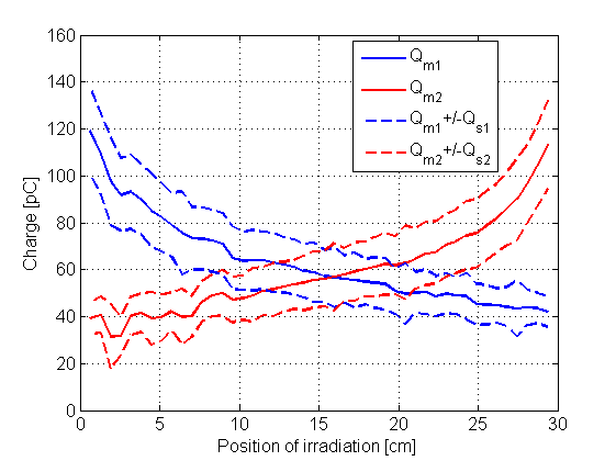
In the first step of the analysis the charge distributions of signals were investigated. Experimental results based on the signals registered along the scintillator strip are presented in Fig. 3. Mean values of charges at PM1(2) are marked with solid blue (red) curves. As expected, the curves are symmetrical with respect to the center of the scintillator strip (position of 15 cm). The distributions of +/- and +/- at PM1(2) along the strip are marked with dashed blue (red) curves. From Fig. 3 one may observe that and have the same trend as and , respectively, and are in the range from about 6 to 20 pC.
3.1 An example of the signal normalization
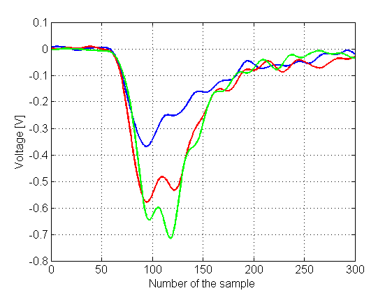
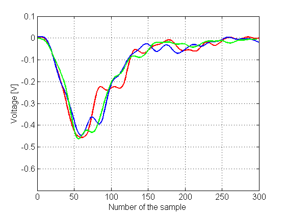
Figure 4 shows an example of the normalization of signals registered at PM1 at fixed position 5 cm from PM1. The three corresponding signals registered at second photomultiplier (PM2) are not shown here, but were used during the normalization process to estimate the position of irradiation (see Eq. 4). The left part of Fig. 4 shows a three randomly selected raw signals registered via scope. The right part of Fig. 4 presents the same signals after the normalization procedure provided according to the description in Sec. 2.4. The same colors of the signals on the left and right part in Fig. 4 indicate a corresponding pair of signals before and after normalization. As it is seen from left part of Fig. 4 the shapes of the three signals are similar but the charges differ. However, an estimated positions according to Eq. 4 were found to be very close, and therefore the charges of the normalized signals were also very similar (see right part of Fig. 4).
 |
 |
3.2 Time resolution of the event time reconstruction
The normalization method was verified using signals from all the irradiation positions. Each pair of signals was recovered via compressed sensing method based on the information from four amplitude levels (see Fig. 2) and next normalized according to the description in Sec. 2.4. In order to compare the time resolutions before and after normalization process, the normalized signals, and , were sampled in the voltage domain at four levels from 50 to 300 mV (see Fig. 2). For each position and at each level the distribution of time difference was calculated.
In Fig. 5 and 6 the resulting resolutions () are presented as a function of irradiated position, determined when applying the lowest threshold (50 mV) and the highest threshold (300 mV), respectively. In Fig. 5 and 6, the resolutions obtained based on the raw and normalized signals are indicated with blue and red squares, respectively. As expected, due to the time walk effect the resolution determined when applying threshold at 50 mV is better with respect to the resolution obtained at 300 mV. However, the influence of time walk effect is more visible in the case of raw signals. From Fig. 5 and 6 one can infer that the time resolution is almost independent of the position of irradiation. An average resolution of the time difference along the strip at the lowest tested amplitude level (Fig. 5) was determined to be 172 ps and 160 ps for the raw and normalized signals, respectively. This corresponds to the improvement of the resolution of the moment of the interaction from 86 ps to about 80 ps.


4 CONCLUSIONS
In this paper the concept of signal normalization in a novel J-PET scanner was introduced. J-PET device is based on plastic scintillators and therefore is a promising solution in view of the TOF resolution. In a related works [10, 11] it was shown that Compressive Sensing theory can be successfully applied to the problem of signal recovery in a J-PET scanner. The information from fully recovered signals was utilized in order to provide the normalization of the signals. It was shown that with fully recovered signals a better time resolution of J-PET scanner is achieved; the resolution of the moment of the interaction was improved from about 86 ps to 80 ps. It should be stressed that different approaches for utilizing the recovered information from Compressive Sensing theory may be considered and the studies are in progress.
5 Acknowledgements
We acknowledge technical and administrative support of T. Gucwa-Ryś, A. Heczko, M. Kajetanowicz, G. Konopka-Cupiał, J. Majewski, W. Migdał, A. Misiak, and the financial support by the Polish National Center for Development and Research through grant INNOTECH-K1/IN1/64/159174/NCBR/12, the Foundation for Polish Science through MPD programme, the EU and MSHE Grant No. POIG.02.03.00-161 00-013/09, Doctus - the Lesser Poland PhD Scholarship Fund.
References
- [1] J. L. Humm et al., From PET detectors to PET scanners Eur. J. Nucl. Med. Mol. Imaging 30 (2003) 1574
- [2] J. S. Karp et al., Benefit of Time-of-Flight in PET: Experimental and Clinical Results J. Nucl. Med. 49 (2008) 462
- [3] M. Conti, State of the art and challenges of time-of-flight PET Phys. Med. 25 (2009) 1
- [4] P. Moskal et al., Novel detector systems for the Positron Emission Tomography, Bio-Algorithms and Med-Systems 7 (2011) 73; [arXiv:1305.5187 [physics.med-ph] ].
- [5] P. Moskal et al., A novel TOF-PET detector based on organic scintillators Radiotheraphy and Oncology 110 (2014) S69.
- [6] P. Moskal et al., Nuclear Instruments and Methods in Physics Research Section A 764 (2014) 317.
- [7] M. Palka et al., A novel method based solely on field programmable gate array (FPGA) units enabling measurement of time and charge of analog signals in positron emission tomography (PET) Bio-Algorithms and Med-Systems 10 (2014) 41; [arXiv:1311.6127 [physics.ins-det] ].
- [8] E. Candes, J. Romberg, T. Tao, IEEE Transaction on Information Theory 52 (2006) 489.
- [9] D. Donoho, IEEE Transaction on Information Theory 52 (2006) 1289.
- [10] L. Raczyński et al., Acta Phys. Polon. B Proceed. Suppl. 6 (2013) 1121, [arXiv:1310.1612 [physics.med-ph]].
- [11] L. Raczyński et al., Nuclear Instruments and Methods in Physics Research Section A, 786 (2015) 105.
- [12] L. Raczyński et al., Nuclear Instruments and Methods in Physics Research Section A, 764 (2014) 186.